EP1900504A2 - Beleuchtungsvorrichtung für ein Fahrzeug und Herstellungsverfahren dafür - Google Patents
Beleuchtungsvorrichtung für ein Fahrzeug und Herstellungsverfahren dafür Download PDFInfo
- Publication number
- EP1900504A2 EP1900504A2 EP07116245A EP07116245A EP1900504A2 EP 1900504 A2 EP1900504 A2 EP 1900504A2 EP 07116245 A EP07116245 A EP 07116245A EP 07116245 A EP07116245 A EP 07116245A EP 1900504 A2 EP1900504 A2 EP 1900504A2
- Authority
- EP
- European Patent Office
- Prior art keywords
- resin member
- resin
- reflector
- lighting device
- semiglossy
- Prior art date
- Legal status (The legal status is an assumption and is not a legal conclusion. Google has not performed a legal analysis and makes no representation as to the accuracy of the status listed.)
- Granted
Links
- 238000004519 manufacturing process Methods 0.000 title claims description 13
- 229920005989 resin Polymers 0.000 claims abstract description 92
- 239000011347 resin Substances 0.000 claims abstract description 92
- 229910052782 aluminium Inorganic materials 0.000 claims abstract description 45
- XAGFODPZIPBFFR-UHFFFAOYSA-N aluminium Chemical compound [Al] XAGFODPZIPBFFR-UHFFFAOYSA-N 0.000 claims abstract description 45
- 239000000945 filler Substances 0.000 claims abstract description 24
- 229920006038 crystalline resin Polymers 0.000 claims abstract description 12
- 238000000034 method Methods 0.000 claims description 14
- 238000000465 moulding Methods 0.000 claims description 14
- 238000000151 deposition Methods 0.000 description 15
- 230000008021 deposition Effects 0.000 description 13
- 229910052751 metal Inorganic materials 0.000 description 7
- 239000002184 metal Substances 0.000 description 7
- 239000000463 material Substances 0.000 description 6
- 238000009499 grossing Methods 0.000 description 5
- -1 polypropylene Polymers 0.000 description 5
- CSNNHWWHGAXBCP-UHFFFAOYSA-L Magnesium sulfate Chemical compound [Mg+2].[O-][S+2]([O-])([O-])[O-] CSNNHWWHGAXBCP-UHFFFAOYSA-L 0.000 description 4
- 239000004743 Polypropylene Substances 0.000 description 3
- 230000003287 optical effect Effects 0.000 description 3
- 230000002093 peripheral effect Effects 0.000 description 3
- 229920001155 polypropylene Polymers 0.000 description 3
- 239000000654 additive Substances 0.000 description 2
- 230000000996 additive effect Effects 0.000 description 2
- TZCXTZWJZNENPQ-UHFFFAOYSA-L barium sulfate Chemical compound [Ba+2].[O-]S([O-])(=O)=O TZCXTZWJZNENPQ-UHFFFAOYSA-L 0.000 description 2
- 239000011248 coating agent Substances 0.000 description 2
- 238000000576 coating method Methods 0.000 description 2
- HCWCAKKEBCNQJP-UHFFFAOYSA-N magnesium orthosilicate Chemical compound [Mg+2].[Mg+2].[O-][Si]([O-])([O-])[O-] HCWCAKKEBCNQJP-UHFFFAOYSA-N 0.000 description 2
- 239000000391 magnesium silicate Substances 0.000 description 2
- 229910052919 magnesium silicate Inorganic materials 0.000 description 2
- 235000019792 magnesium silicate Nutrition 0.000 description 2
- 229910052943 magnesium sulfate Inorganic materials 0.000 description 2
- 235000019341 magnesium sulphate Nutrition 0.000 description 2
- 229920001707 polybutylene terephthalate Polymers 0.000 description 2
- 229920000515 polycarbonate Polymers 0.000 description 2
- 239000004417 polycarbonate Substances 0.000 description 2
- 239000004734 Polyphenylene sulfide Substances 0.000 description 1
- 230000003796 beauty Effects 0.000 description 1
- 150000001875 compounds Chemical class 0.000 description 1
- 238000009826 distribution Methods 0.000 description 1
- 230000000694 effects Effects 0.000 description 1
- 230000002708 enhancing effect Effects 0.000 description 1
- 239000010954 inorganic particle Substances 0.000 description 1
- 230000010354 integration Effects 0.000 description 1
- 230000001788 irregular Effects 0.000 description 1
- 238000002844 melting Methods 0.000 description 1
- 230000008018 melting Effects 0.000 description 1
- 239000000203 mixture Substances 0.000 description 1
- 239000002245 particle Substances 0.000 description 1
- 238000005498 polishing Methods 0.000 description 1
- 229920000728 polyester Polymers 0.000 description 1
- 229920001225 polyester resin Polymers 0.000 description 1
- 239000004645 polyester resin Substances 0.000 description 1
- 229920000069 polyphenylene sulfide Polymers 0.000 description 1
- 230000001105 regulatory effect Effects 0.000 description 1
- 238000005480 shot peening Methods 0.000 description 1
- 238000004381 surface treatment Methods 0.000 description 1
- 239000000454 talc Substances 0.000 description 1
- 229910052623 talc Inorganic materials 0.000 description 1
Images


Classifications
-
- B—PERFORMING OPERATIONS; TRANSPORTING
- B29—WORKING OF PLASTICS; WORKING OF SUBSTANCES IN A PLASTIC STATE IN GENERAL
- B29D—PRODUCING PARTICULAR ARTICLES FROM PLASTICS OR FROM SUBSTANCES IN A PLASTIC STATE
- B29D11/00—Producing optical elements, e.g. lenses or prisms
- B29D11/00596—Mirrors
-
- F—MECHANICAL ENGINEERING; LIGHTING; HEATING; WEAPONS; BLASTING
- F21—LIGHTING
- F21S—NON-PORTABLE LIGHTING DEVICES; SYSTEMS THEREOF; VEHICLE LIGHTING DEVICES SPECIALLY ADAPTED FOR VEHICLE EXTERIORS
- F21S41/00—Illuminating devices specially adapted for vehicle exteriors, e.g. headlamps
- F21S41/30—Illuminating devices specially adapted for vehicle exteriors, e.g. headlamps characterised by reflectors
- F21S41/37—Illuminating devices specially adapted for vehicle exteriors, e.g. headlamps characterised by reflectors characterised by their material, surface treatment or coatings
-
- F—MECHANICAL ENGINEERING; LIGHTING; HEATING; WEAPONS; BLASTING
- F21—LIGHTING
- F21S—NON-PORTABLE LIGHTING DEVICES; SYSTEMS THEREOF; VEHICLE LIGHTING DEVICES SPECIALLY ADAPTED FOR VEHICLE EXTERIORS
- F21S43/00—Signalling devices specially adapted for vehicle exteriors, e.g. brake lamps, direction indicator lights or reversing lights
- F21S43/30—Signalling devices specially adapted for vehicle exteriors, e.g. brake lamps, direction indicator lights or reversing lights characterised by reflectors
- F21S43/33—Signalling devices specially adapted for vehicle exteriors, e.g. brake lamps, direction indicator lights or reversing lights characterised by reflectors characterised by their material, surface treatment or coatings
-
- F—MECHANICAL ENGINEERING; LIGHTING; HEATING; WEAPONS; BLASTING
- F21—LIGHTING
- F21S—NON-PORTABLE LIGHTING DEVICES; SYSTEMS THEREOF; VEHICLE LIGHTING DEVICES SPECIALLY ADAPTED FOR VEHICLE EXTERIORS
- F21S43/00—Signalling devices specially adapted for vehicle exteriors, e.g. brake lamps, direction indicator lights or reversing lights
- F21S43/50—Signalling devices specially adapted for vehicle exteriors, e.g. brake lamps, direction indicator lights or reversing lights characterised by aesthetic components not otherwise provided for, e.g. decorative trim, partition walls or covers
-
- F—MECHANICAL ENGINEERING; LIGHTING; HEATING; WEAPONS; BLASTING
- F21—LIGHTING
- F21V—FUNCTIONAL FEATURES OR DETAILS OF LIGHTING DEVICES OR SYSTEMS THEREOF; STRUCTURAL COMBINATIONS OF LIGHTING DEVICES WITH OTHER ARTICLES, NOT OTHERWISE PROVIDED FOR
- F21V7/00—Reflectors for light sources
- F21V7/22—Reflectors for light sources characterised by materials, surface treatments or coatings, e.g. dichroic reflectors
- F21V7/24—Reflectors for light sources characterised by materials, surface treatments or coatings, e.g. dichroic reflectors characterised by the material
-
- Y—GENERAL TAGGING OF NEW TECHNOLOGICAL DEVELOPMENTS; GENERAL TAGGING OF CROSS-SECTIONAL TECHNOLOGIES SPANNING OVER SEVERAL SECTIONS OF THE IPC; TECHNICAL SUBJECTS COVERED BY FORMER USPC CROSS-REFERENCE ART COLLECTIONS [XRACs] AND DIGESTS
- Y10—TECHNICAL SUBJECTS COVERED BY FORMER USPC
- Y10T—TECHNICAL SUBJECTS COVERED BY FORMER US CLASSIFICATION
- Y10T428/00—Stock material or miscellaneous articles
- Y10T428/26—Web or sheet containing structurally defined element or component, the element or component having a specified physical dimension
- Y10T428/269—Web or sheet containing structurally defined element or component, the element or component having a specified physical dimension including synthetic resin or polymer layer or component
Definitions
- the present disclosure relates to a lighting device for a vehicle comprising a reflector or a dummy reflector, and more particularly to a lighting device for a vehicle in which a design effect of a reflector surface is enhanced and a method of manufacturing the lighting device for a vehicle.
- an extension a dummy reflector
- This is intended for an object of a design that the reflector is constituted as a reflecting plane, and furthermore, a sense of gloss is given to the extension observed from an outside through a front cover of the lamp to have a sense of integration with the reflector.
- polyester, polypropylene or polyphenylene sulfide is used for a resin material.
- concavo-convex portions are easily generated on a surface of a molded resin.
- a surface of the aluminum deposited layer formed on the surface has a low regular reflectance and it is hard to obtain a mirror finished surface.
- Japanese Patent Unexamined Publication No. 8-264013 there has been proposed a technique for smoothing a surface of a resin molded by characterizing an amount of addition of talc or barium sulfate acting as a filler to be added to polypropylene and directly depositing aluminum on the surface of the molded resin, thereby obtaining a mirror finished surface.
- Japanese Patent Unexamined Publication No. 2002-60600 has also proposed a technique for characterizing a size and number of particles of an inorganic particle containing a polyester resin composition, particularly, a layered compound in order to improve a moldability of a resin and to enhance a flatness of the surface.
- a region other than an effective reflecting plane of a reflector for reflecting a light emitted from a light source and a surface of an extension are set to be a semiglossy surface such as a reflecting plane having a low regular reflectance or a diffusing and reflecting plane to improve a design beauty of the lamp and to obtain a sense of high quality in the lamp.
- fine concavo-convex portions are formed on a resin surface in a region corresponding to a non-effective reflecting plane of a resin to be a main body of the reflector and the extension and an aluminum deposited layer is formed thereon to intentionally form a fine concave-convex surface, that is, a so-called embossed surface on the surface of the aluminum deposited layer and to irregularly reflect or to diffuse and reflect a light over the embossed surface.
- a surface such as the embossed surface will be referred to as a semiglossy surface.
- a semiglossy surface having a predetermined pattern is mixed into a partial region of the mirror finished surfaces of the reflector and the extension. Consequently, a sense of gloss of the reflector and the extension is suppressed so that a designing property can be enhanced and a sense of high quality can be obtained.
- the resin according to JP2002-60600 is not assumed to be applied to the technique for forming the aluminum deposited layer on the surface to form the glossy surface or the semiglossy film as in JP8-264013 .
- the aluminum deposited layer is actually formed on the surface by direct deposition, therefore, concavo-convex portions are generated on the surface depending on a shrinkage difference in a reduction in temperatures of the resin which is molded and deposited and the aluminum deposited layer so that a regular reflectance is reduced and a mirror finished surface cannot be obtained. For this reason, it is supposed that an application to a lamp for a vehicle is hard.
- Exemplary embodiments of the present invention provide a lighting device for a vehicle which can obtain a sense of high quality on a design basis by mixing a mirror finished surface and a semiglossy surface into a surface of a component such as a reflector or an extension, and a manufacturing method capable of easily manufacturing the lighting device for a vehicle.
- An aspect of the present invention provides a lighting device for a vehicle which comprises a component of the lighting device in which an aluminum deposited layer is formed on a surface of a resin member, wherein the resin member is molded by a resin obtained by adding, to a crystalline resin, a filler having a size smaller than a wavelength of a visible light, a smooth surface and a fine concavo-convex surface are mixed into the surface of the resin member which is molded, the aluminum deposited layer is directly deposited on the surface of the resin member, and the smooth surface is formed as a mirror finished surface and the fine concavo-convex surface is formed as a semiglossy surface.
- a component of a lighting device is a reflector or an extension provided in a lighting device body, and at least an effective reflecting plane of the reflector is formed by a mirror finished surface and a semiglossy surface is provided in a residual region of the reflector or at least a part of the extension.
- a lighting device for a vehicle which comprises a component including a resin member and an aluminum deposited layer directly formed on a surface of the resin member, wherein the resin member is formed by a crystalline resin with a filler, the filler having a size smaller than a wavelength of a visible light, and the resin member has a smooth surface and a fine concavo-convex surface, wherein the component has a mirror finished surface formed on the smooth surface of the resin member, and a semiglossy surface formed on the fine concavo-convex surface of the resin member.
- the fine concavo-convex surface of the resin member has a concavo-convex height of 5 to 10 ⁇ m.
- Another aspect of the present invention provides a method of manufacturing a lighting device for a vehicle including a component of the lighting device in which an aluminum deposited layer is formed on a surface of a resin member, comprising the steps of molding a resin member in which at least a part of a surface is a smooth surface and at least a part of the other portion has a fine concavo-convex surface through a resin obtained by adding, to a crystalline resin, a filler having a size smaller than a wavelength of a visible light, and directly forming an aluminum deposited layer on the surface of the resin member.
- the fine concavo-convex surface of the resin member is formed to have a concavo-convex height of 5 to 10 ⁇ m.
- the semiglossy surface is formed in a predetermined pattern on a part of the mirror finished surface over the surface of the component of the lighting device such as a reflector or an extension, and the mirror finished surface and the semiglossy surface are observed from the outside of the lighting device.
- the component of the lighting device is constituted by only a simple mirror finished surface, therefore, a sense of gloss is suppressed as a whole by the presence of the semiglossy surface designed in a proper area.
- the manufacturing method in accordance with the present invention moreover, it is possible to form, as a mirror finished surface, a surface of a part of the components of the lighting device and to form a surface of a part of the other components as a semiglossy surface by simply molding the components of the lighting device with a resin and then forming the aluminum deposited layer on the surface through direct deposition. Therefore, there is not required a step of smoothing a part of the surface after carrying out molding as in the related art and a step of forming concavo-convex portions on a part of the surface. Thus, it is possible to manufacture a lighting device requiring a lower cost and labor requirements.
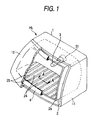
- Fig. 1 is a perspective view showing the first exemplary embodiment of a headlamp HL for a vehicle, a part of which is cut away
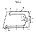
- Fig. 2 is a longitudinal sectional view showing the same.
- a lamp housing 1 is constituted by a lamp body 11 taking a front shape which is close to a rectangular shape, a front lens 12 attached to a front opening of the lamp body 11 and formed by a transparent resin, a back cover 13 for covering a back opening of the lamp body 11, and a reflector 2 is provided in the lamp housing 1.
- a bulb attaching hole 21 is formed on a back face of the reflector 2 and an incandescent bulb or a discharge bulb 3 to be a light source is attached by means of a bulb socket 31.
- the reflector 2 can be tilted vertically and transversely by means of an aiming mechanism which is not shown. Consequently, positions of central optical axes of the light source 3 and the reflector 2 can be deflected and regulated.
- an extension 4 taking a shape of an almost rectangular frame seen from a front is provided to hide a clearance generated between a front opening peripheral edge portion 2a of the reflector 2 and an internal surface of the lamp body 11, and is fixed and supported in the lamp body 1 in such a state as to be separated from the reflector 2 in order not to damage an aiming operation of the reflector 2.
- the reflector 2 and the extension 4 are components of the lighting device.
- the reflector 2 has an effective reflecting plane 22 to be a rotating paraboloid and a non-effective reflecting plane 23 taking a shape of an almost rectangular cylinder which is constituted by a vertical plane extended forward from a periphery of the effective reflecting plane 22 and a transverse surface.
- a light emitted from the light source 3 is reflected by the effective reflecting plane 22 and is refracted and collected by the front lens 12 so that a light is irradiated in a predetermined light distribution pattern in a forward direction of a vehicle. Moreover, a part of the light emitted from the light source 3 is projected onto the non-effective reflecting plane 23. The light to be reflected is emitted through the front lens 12. Herein, the same light is reflected in such a direction as not to daze a vehicle running on an opposing lane or a pedestrian.
- an aluminum deposited layer is formed through direct deposition on a surface of a resin member obtained by molding a resin, and the effective reflecting plane 22 is formed as a mirror finished surface (a glossy surface) by the aluminum deposited layer and most of the non-effective reflecting plane 23 is formed as a mirror finished surface.
- a part of the non-effective reflecting plane 23, that is, a lower surface is provided with semiglossy surfaces 24 in a grid-like pattern in which a mirror finished surface 25 having a minute interval in a transverse direction is disposed therebetween when the headlamp HL is seen from a front.
- the semiglossy surface 24 is constituted by a band-shaped embossed surface.
- the extension 4 is obtained by molding a resin material to take a shape of an almost rectangular frame and forming an aluminum deposited layer as a mirror finished surface on a surface through direct deposition.
- the semiglossy surface is not formed on the extension 4.
- the aluminum deposited layer is formed through direct deposition on the surface of the molded resin member in the same manner. Therefore, description will be given to an example of the reflector 2.
- polybutylene terephthalate referred to as a crystalline resin is used for a resin and magnesium sulfate (MgSO 2 ) or magnesium silicate (MgSiO) is contained as a filler (an additive material) therein.
- MgSO 2 magnesium sulfate
- MgSiO magnesium silicate
- this type of filler to be used has a size of 400 nm or more. In the first exemplary embodiment, however, the filler to be used has a size smaller than 400 nm.
- 400 nm is set to be a dimension smaller than the smallest wavelength of a visible light.
- a wavelength region of the visible light is set to be 400 nm to 800 nm. For this reason, a size smaller than 400 nm is set.
- the resin is molded as a resin member taking a shape of the reflector 2 by means of a metal mold.
- a molding surface of the metal mold K is formed in such a manner that a region corresponding to the mirror finished surface 25 of the reflector 2 is a smooth surface including a maximum concavo-convex portion having a size of 0.2 ⁇ m or less.
- a fine concavo-convex groove Kg is formed on a surface in a region corresponding to the semiglossy surface 24.
- the fine concavo-convex groove has a height (a difference of elevation) of approximately 5 to 10 ⁇ m.
- a grid is formed by an array in which a predetermined number of fine concavo-convex grooves including a rectangular section having a height of 5 ⁇ m are arranged in a direction of a width thereof, and the grid is arranged in a plurality of lines at a predetermined interval.
- a region corresponding to the mirror finished surface 25 of the reflector 2 is formed as a smooth surface including a maximum concavo-convex portion having a size of 0.2 ⁇ m or less as shown in a section of Fig. 3C.
- a plurality of fine concavo-convex grooves 24a is arranged like a grid on a surface of a region corresponding to the semiglossy surface 24, and is formed as a so-called band-shaped embossed surface.
- an aluminum deposited layer 26 is formed through the direct deposition on the surface of the reflector 2, that is, surfaces to be the reflecting plane 22 and the non-reflecting plane 23.
- the direct deposition indicates a method of directly depositing aluminum without applying an undercoat onto the surface of the resin.
- the aluminum deposited layer 26 has a thickness of approximately 0.1 ⁇ m.
- a concavo-convex portion is generated on a surface of the molded resin member due to a shrinkage difference between a resin R and a filler F when a temperature is lowered.
- the concavo-convex portion is influenced by a size of the filler F contained in the resin R.
- the filler contained in the resin R has a great size of approximately 10 ⁇ m. Therefore, the concavo-convex portion provided on the surface has a size of approximately 1 ⁇ m.
- the filler contained in the resin R has a size smaller than 10 nm (0.01 ⁇ m).
- the concavo-convex portion provided on the surface is 10 nm.
- a wavelength of a visible light is equal to or greater than 400 nm and is greater than a height of the concavo-convex portion generated on the surface of the resin member R. Even if a concavo-convex portion having a size smaller than 400 nm is generated, the light is regularly reflected.
- the surface of the molded resin member is a smooth surface including a concavo-convex portion having a size of 10 nm or less.
- the surface of the aluminum deposited layer 26 obtained through direct deposition is also smoothed and is formed as the mirror finished surface 25.
- the filler has a size which is equal to or smaller than the wavelength of the visible light, that is, 400 nm, accordingly, the concavo-convex portion provided on the surface of the resin has a size of 400 nm or less. Therefore, it is possible to use the filler having the size of 400 nm or less.
- a part of the non-effective reflecting plane 23 of the reflector 2 is formed as the mirror finished surface 25, and the other part is formed as a band-shaped embossed surface.
- the band-shaped embossed surface acts as the semiglossy surface 24 through the aluminum deposited layer 26.
- the concavo-convex groove 24a has a height of 5 ⁇ m and the undercoat is not formed on the surface of the concavo-convex groove 24a. Therefore, the concavo-convex groove 24a can be prevented from being filled with the undercoat.
- the aluminum deposited layer 26 has a thickness of 0.1 ⁇ m.
- the height of the concave-convex groove 24a is rarely influenced and the surface of the aluminum deposited layer 26 becomes a fine concavo-convex surface.
- the height of 5 ⁇ m of the concavo-convex groove 24a is much greater as compared with the wavelength of the visible light. Therefore, the visible light is reflected irregularly so that the concavo-convex surface is not a mirror finished surface but a semiglossy surface.
- the non-effective reflecting plane 23 of the reflector 2 is provided with the grid-like pattern in which a plurality of wide semiglossy surfaces 24 is arranged with the thin mirror finished surface 25 interposed therebetween.
- the semiglossy surfaces 24 and the mirror finished surface 25 therebetween in the grid-like pattern are observed from the outside through the front lens 12 of the headlamp HL.
- a whole surface is formed as a mirror finished surface.
- the semiglossy surface 24 in the grid-like pattern which is designed to have a proper area is present in the mirror surface of the reflector 2 so that a sense of gloss in the whole reflector 2 can be suppressed and a sense of high quality can be obtained when the headlamp HL is seen in the non-lighting.
- the resin containing the filler having a size smaller than the wavelength of the visible light in the crystalline resin as the resin member constituting the reflector 2 and forming the aluminum deposited layer through direct deposition on the surface after molding the resin it is possible to form a part of the surface as the mirror finished surface and the other part of the surface as the semiglossy surface. Consequently, it is possible to manufacture a reflector having an excellent designing property and to constitute a lamp having a sense of high quality. Therefore, there is not required a step of smoothing a part of the surface after carrying out molding as in the related art and a step of forming concavo-convex portions in a part of the surface. Consequently, it is possible to manufacture a lamp requiring low cost and labor.
- Fig. 5 is a schematic partial exploded perspective view in which a lamp according to a second exemplary embodiment is applied to a headlamp HL1 for a vehicle.
- a so-called lamp of a projector type is constituted as the headlamp HL1 incorporated in a lamp housing.
- a lamp housing 101 is constituted by a lamp body 111 and a front cover 112, and a lamp 102 of a projector type for a high beam and a lamp 103 of a projector type for a low beam are transversely arranged and disposed in a state in which they are slightly shifted from each other in a longitudinal direction in the lamp housing 101. Since the structure of the lamp of the projector type has already been known, detailed description will be omitted.
- the lamp of the projector type serves to reflect a light emitted from a light source (not shown) provided in reflectors 121 and 131 disposed in a rear part by internal surfaces of the reflectors 121 and 131 and to collect the reflected light by lenses 122 and 132 provided in a front part, and to then emit the same light in a direction of an optical axis of the lamp.
- a light source not shown
- an extension 104 is provided in order to hide the periphery of the lamps 102 and 103 of the projector type in the lamp housing 101.
- the extension 104 takes an external shape corresponding to a front opening of the lamp body 111 and has a middle zone part in which circular sleeve openings 141 and 142 taking almost cylindrical shapes and serving to accommodate the lamps 102 and 103 of the projector type are formed, and the lamps 102 and 103 of the projector type are inserted internally from rear parts of the sleeve openings 141 and 142 and the respective lenses 122 and 132 are exposed to a front side of the extension 104.
- a front region of the sleeve openings 141 and 142 is provided with a semiglossy surface 144 having a grid-like pattern in which a plurality of semiglossy surfaces having small widths extended in the direction of the optical axis is arranged in a transverse direction.
- polybutylene terephthalate to be a crystalline resin is used and is caused to contain magnesium sulfate (MgSO 2 ) or magnesium silicate (MgSiO) having a size smaller than 400 nm as a filler (an additive material) .
- the resin is molded to form an extension by means of a metal mold subjected to a surface treatment in the same manner as in the first exemplary embodiment shown in Figs. 3A-3C.
- a region corresponding to the mirror finished surface is formed as a smooth surface having a maximum concavo-convex portion of 0.2 ⁇ m or less, and a region corresponding to the semiglossy surface has a surface provided with fine band-shaped concavo-convex portions which are constituted by a large number of concavo-convex grooves taking a rectangular section having a height (a depth) of 5 ⁇ m.
- an aluminum deposited layer is formed on the surface of the extension through direct deposition. The aluminum deposited layer has a thickness of approximately 0.1 ⁇ m.
- the mirror finished surface 143 is formed on the smooth surface of the extension 104, and similarly, a band-shaped embossed surface is formed in a region of the extension 104 in which band-shaped concavo-convex portions are formed and the semiglossy surface 144 is thus formed.
- a lower peripheral region of internal peripheral surfaces of the sleeve openings 141 and 142 is provided with the semiglossy surface 144 having a grid-like pattern in which wide semiglossy surfaces having a thin mirror finished surface interposed therebetween are formed like a grid.
- the extension 104 is exposed to a front side of the headlamp HL1 through the front cover 112, and at the same time, the mirror finished surface 143 and the semiglossy surface 144 in the extension 104 are also exposed.
- the extension 104 having most parts formed as the mirror finished surface 143 and a part formed as the semiglossy surface 144 is observed through the front cover 112.
- the extension 104 is constituted by only a simple mirror finished surface, consequently, a semiglossy surface designed to have a proper area is present so that a sense of gloss for the whole extension can be suppressed and a sense of high quality can be obtained when the lamp is seen in the non-lighting condition.
- the resin containing the filler having a size smaller than the wavelength of the visible light in the crystalline resin as the resin constituting the extension to form the aluminum deposited layer through the direct deposition on the surface of the molded resin member, it is possible to form a part of the surface as the mirror finished surface and the other part of the surface as the semiglossy surface. Consequently, it is possible to manufacture an extension having an excellent designing property and to constitute a lamp having a sense of high quality. Therefore, there is not required a step of smoothing a part of the surface after carrying out molding as in the related art and a step of forming concavo-convex portions in a part of the surface. Consequently, it is possible to manufacture a lamp requiring low cost and labor.
- the semiglossy surface is formed in a part of the reflector in the first exemplary embodiment and the semiglossy surface is formed in a part of the extension in the second exemplary embodiment, the semiglossy surface may be formed on either or both of the reflector and the extension in a lamp in which they are provided as in the first exemplary embodiment. In the case of an application to the extension, moreover, a whole surface or most parts thereof may be formed as the semiglossy surface.
- the embossed surface constituting the semiglossy surface is formed as the band-shaped embossed surface in the first and second exemplary embodiments, it may be formed as an embossed surface having dot-like concavo-convex portions or an embossed surface constituted by concavo-convex portions taking irregular shapes.
- the present invention is not restricted to the headlamps according to the first and second exemplary embodiments but it is also possible to apply a lamp comprising components of a lighting device in which a resin is molded to form an aluminum deposited layer on a surface, for example, a reflector and an extension and having a structure in which the surfaces of the components of the lighting device are observed from an outside of the lamp in the same manner.
Landscapes
- Engineering & Computer Science (AREA)
- General Engineering & Computer Science (AREA)
- Health & Medical Sciences (AREA)
- Manufacturing & Machinery (AREA)
- Ophthalmology & Optometry (AREA)
- Mechanical Engineering (AREA)
- Non-Portable Lighting Devices Or Systems Thereof (AREA)
- Optical Elements Other Than Lenses (AREA)
Applications Claiming Priority (1)
| Application Number | Priority Date | Filing Date | Title |
|---|---|---|---|
| JP2006247590A JP5180454B2 (ja) | 2006-09-13 | 2006-09-13 | 車両用灯具及びその製造方法 |
Publications (3)
| Publication Number | Publication Date |
|---|---|
| EP1900504A2 true EP1900504A2 (de) | 2008-03-19 |
| EP1900504A3 EP1900504A3 (de) | 2009-02-18 |
| EP1900504B1 EP1900504B1 (de) | 2013-07-03 |
Family
ID=38830437
Family Applications (1)
| Application Number | Title | Priority Date | Filing Date |
|---|---|---|---|
| EP07116245.7A Not-in-force EP1900504B1 (de) | 2006-09-13 | 2007-09-12 | Beleuchtungsvorrichtung für ein Fahrzeug und Herstellungsverfahren dafür |
Country Status (4)
| Country | Link |
|---|---|
| US (1) | US7762694B2 (de) |
| EP (1) | EP1900504B1 (de) |
| JP (1) | JP5180454B2 (de) |
| CN (1) | CN101144584B (de) |
Cited By (2)
| Publication number | Priority date | Publication date | Assignee | Title |
|---|---|---|---|---|
| WO2009130123A1 (en) * | 2008-04-21 | 2009-10-29 | Fael S.P.A. | Plating reflectors process for outdoor and indoor spotlights |
| FR2935115A1 (fr) * | 2008-08-21 | 2010-02-26 | Peugeot Citroen Automobiles Sa | Masque de bloc optique de vehicule automobile a insert(s) interchangeable(s) |
Families Citing this family (7)
| Publication number | Priority date | Publication date | Assignee | Title |
|---|---|---|---|---|
| WO2010113511A1 (ja) | 2009-03-31 | 2010-10-07 | 株式会社フジクラ | 装飾部材 |
| JP5941253B2 (ja) | 2011-08-22 | 2016-06-29 | 株式会社小糸製作所 | 車輌用灯具 |
| JP5840936B2 (ja) * | 2011-11-25 | 2016-01-06 | 株式会社小糸製作所 | 車両用灯具及びその製造方法 |
| JP5948066B2 (ja) | 2012-01-30 | 2016-07-06 | 株式会社小糸製作所 | 車両用灯具及びその製造方法 |
| JP6096529B2 (ja) * | 2013-02-15 | 2017-03-15 | スタンレー電気株式会社 | 車両用灯具ユニット |
| JP6519347B2 (ja) * | 2015-06-25 | 2019-05-29 | 市光工業株式会社 | 車両用灯具 |
| JP7280739B2 (ja) * | 2019-04-08 | 2023-05-24 | 株式会社小糸製作所 | 反射性樹脂部材および車両用灯具 |
Citations (4)
| Publication number | Priority date | Publication date | Assignee | Title |
|---|---|---|---|---|
| JPH04368702A (ja) | 1991-06-15 | 1992-12-21 | Koito Mfg Co Ltd | 自動車用ヘッドランプ |
| JPH08264013A (ja) | 1995-03-23 | 1996-10-11 | Ichikoh Ind Ltd | 車両用灯具の反射膜構造 |
| US5760159A (en) | 1995-11-01 | 1998-06-02 | Bakelite Ag | Reflector as well as process and means for its production |
| JP2002060600A (ja) | 2000-08-23 | 2002-02-26 | Kanegafuchi Chem Ind Co Ltd | ポリエステル樹脂組成物 |
Family Cites Families (11)
| Publication number | Priority date | Publication date | Assignee | Title |
|---|---|---|---|---|
| JPH08315612A (ja) * | 1995-05-16 | 1996-11-29 | Ichikoh Ind Ltd | 灯 具 |
| JP2003033988A (ja) * | 2001-07-23 | 2003-02-04 | Kanegafuchi Chem Ind Co Ltd | 照明部品用樹脂成形体 |
| JP2004111180A (ja) * | 2002-09-18 | 2004-04-08 | Koito Mfg Co Ltd | 車輌用灯具 |
| FR2848285B1 (fr) * | 2002-12-05 | 2005-12-16 | Valeo Vision | Procede de realisation d'une fonction optique sur un composant d'un dispositif d'eclairage ou de signalisation automobile |
| JP2004288585A (ja) * | 2003-03-25 | 2004-10-14 | Matsushita Electric Ind Co Ltd | 面発光装置 |
| JP4346957B2 (ja) * | 2003-05-22 | 2009-10-21 | 三菱レイヨン株式会社 | 振動溶着用樹脂組成物、並びにそれを用いた成形品、自動車用ランプ |
| JP2005015519A (ja) * | 2003-06-23 | 2005-01-20 | Nissan Motor Co Ltd | 樹脂組成物とその製造方法 |
| DE10338840A1 (de) * | 2003-08-23 | 2006-01-12 | Hella Kgaa Hueck & Co. | Verfahren zur Strukturierung mindestens eines Abschnittes einer lichttechnischen Oberfläche sowie Beleuchtungsvorrichtung für ein Kraftfahrzeug mit einer derartigen lichttechnischen Oberfläche |
| JP5284557B2 (ja) * | 2003-12-26 | 2013-09-11 | 三菱レイヨン株式会社 | 光反射体 |
| GB2419884B (en) | 2003-08-26 | 2008-03-12 | Mitsubishi Rayon Co | Thermoplastic resin composition for light reflector,molded article for light reflector,light reflector & method for producing molded article. |
| JP4358076B2 (ja) * | 2004-09-17 | 2009-11-04 | 株式会社小糸製作所 | 車両用灯具 |
-
2006
- 2006-09-13 JP JP2006247590A patent/JP5180454B2/ja not_active Expired - Fee Related
-
2007
- 2007-09-12 CN CN2007101489829A patent/CN101144584B/zh not_active Expired - Fee Related
- 2007-09-12 EP EP07116245.7A patent/EP1900504B1/de not_active Not-in-force
- 2007-09-13 US US11/854,598 patent/US7762694B2/en not_active Expired - Fee Related
Patent Citations (4)
| Publication number | Priority date | Publication date | Assignee | Title |
|---|---|---|---|---|
| JPH04368702A (ja) | 1991-06-15 | 1992-12-21 | Koito Mfg Co Ltd | 自動車用ヘッドランプ |
| JPH08264013A (ja) | 1995-03-23 | 1996-10-11 | Ichikoh Ind Ltd | 車両用灯具の反射膜構造 |
| US5760159A (en) | 1995-11-01 | 1998-06-02 | Bakelite Ag | Reflector as well as process and means for its production |
| JP2002060600A (ja) | 2000-08-23 | 2002-02-26 | Kanegafuchi Chem Ind Co Ltd | ポリエステル樹脂組成物 |
Cited By (2)
| Publication number | Priority date | Publication date | Assignee | Title |
|---|---|---|---|---|
| WO2009130123A1 (en) * | 2008-04-21 | 2009-10-29 | Fael S.P.A. | Plating reflectors process for outdoor and indoor spotlights |
| FR2935115A1 (fr) * | 2008-08-21 | 2010-02-26 | Peugeot Citroen Automobiles Sa | Masque de bloc optique de vehicule automobile a insert(s) interchangeable(s) |
Also Published As
| Publication number | Publication date |
|---|---|
| JP5180454B2 (ja) | 2013-04-10 |
| US7762694B2 (en) | 2010-07-27 |
| EP1900504B1 (de) | 2013-07-03 |
| CN101144584B (zh) | 2013-07-10 |
| EP1900504A3 (de) | 2009-02-18 |
| US20080063862A1 (en) | 2008-03-13 |
| JP2008071556A (ja) | 2008-03-27 |
| CN101144584A (zh) | 2008-03-19 |
Similar Documents
| Publication | Publication Date | Title |
|---|---|---|
| EP1900504B1 (de) | Beleuchtungsvorrichtung für ein Fahrzeug und Herstellungsverfahren dafür | |
| JP4223805B2 (ja) | 車両用ヘッドライトレンズ | |
| JP5879876B2 (ja) | 車両用灯具ユニット | |
| JPH0714407A (ja) | 車両用灯具 | |
| JP2014502779A (ja) | Ledランプモジュール | |
| JPH08255501A (ja) | 車両用灯具 | |
| CN110337565B (zh) | 用于机动车前照灯的前照灯透镜 | |
| JP3579930B2 (ja) | 自動車用ヘッドライト、及びこのヘッドライトの反射鏡を製造する方法 | |
| JP2007324002A (ja) | 車両用灯具 | |
| JP2008276958A (ja) | 車両用灯具 | |
| EP1686313B1 (de) | Fahrzeugbeleuchtungsvorrichtung und Scheinwerfereinheit für Fahrzeuge einschliessend die Beleuchtungsvorrichtung | |
| CN106573574A (zh) | 具有选择性反射的后视镜和制造方法 | |
| US10760764B2 (en) | Partial metallization of molded part using ablation | |
| JP2012256442A (ja) | 車両用灯具 | |
| ES2389777T3 (es) | Revestimiento retrorreflectante que comprende una capa de mejora de la divergencia | |
| JPH1050103A (ja) | 車両用灯具 | |
| JP6920015B2 (ja) | 車両用灯具 | |
| JP2012089317A (ja) | 灯具ユニット | |
| CN120418583A (zh) | 车辆用灯具 | |
| JP4389895B2 (ja) | 車両用前照灯 | |
| TWM561628U (zh) | 車燈 | |
| JP3853980B2 (ja) | 面発光ランプ装置 | |
| KR102956520B1 (ko) | 차량용 램프 | |
| JP4761971B2 (ja) | 灯具 | |
| JP4009452B2 (ja) | 横長レンズプロジェクター型ヘッドランプ |
Legal Events
| Date | Code | Title | Description |
|---|---|---|---|
| PUAI | Public reference made under article 153(3) epc to a published international application that has entered the european phase |
Free format text: ORIGINAL CODE: 0009012 |
|
| 17P | Request for examination filed |
Effective date: 20071002 |
|
| AK | Designated contracting states |
Kind code of ref document: A2 Designated state(s): AT BE BG CH CY CZ DE DK EE ES FI FR GB GR HU IE IS IT LI LT LU LV MC MT NL PL PT RO SE SI SK TR |
|
| AX | Request for extension of the european patent |
Extension state: AL BA HR MK YU |
|
| PUAL | Search report despatched |
Free format text: ORIGINAL CODE: 0009013 |
|
| AK | Designated contracting states |
Kind code of ref document: A3 Designated state(s): AT BE BG CH CY CZ DE DK EE ES FI FR GB GR HU IE IS IT LI LT LU LV MC MT NL PL PT RO SE SI SK TR |
|
| AX | Request for extension of the european patent |
Extension state: AL BA HR MK RS |
|
| RIC1 | Information provided on ipc code assigned before grant |
Ipc: B29D 11/00 20060101AFI20080103BHEP Ipc: F21V 7/22 20060101ALI20090109BHEP |
|
| AKX | Designation fees paid |
Designated state(s): DE FR GB |
|
| 17Q | First examination report despatched |
Effective date: 20100823 |
|
| GRAP | Despatch of communication of intention to grant a patent |
Free format text: ORIGINAL CODE: EPIDOSNIGR1 |
|
| RIN1 | Information on inventor provided before grant (corrected) |
Inventor name: IKEDA, TOSHIMASA Inventor name: KOHATA, TAKAHIRO |
|
| GRAS | Grant fee paid |
Free format text: ORIGINAL CODE: EPIDOSNIGR3 |
|
| GRAA | (expected) grant |
Free format text: ORIGINAL CODE: 0009210 |
|
| AK | Designated contracting states |
Kind code of ref document: B1 Designated state(s): DE FR GB |
|
| REG | Reference to a national code |
Ref country code: GB Ref legal event code: FG4D |
|
| REG | Reference to a national code |
Ref country code: DE Ref legal event code: R096 Ref document number: 602007031361 Country of ref document: DE Effective date: 20130829 |
|
| PLBE | No opposition filed within time limit |
Free format text: ORIGINAL CODE: 0009261 |
|
| STAA | Information on the status of an ep patent application or granted ep patent |
Free format text: STATUS: NO OPPOSITION FILED WITHIN TIME LIMIT |
|
| 26N | No opposition filed |
Effective date: 20140404 |
|
| REG | Reference to a national code |
Ref country code: DE Ref legal event code: R097 Ref document number: 602007031361 Country of ref document: DE Effective date: 20140404 |
|
| PGFP | Annual fee paid to national office [announced via postgrant information from national office to epo] |
Ref country code: GB Payment date: 20140910 Year of fee payment: 8 |
|
| REG | Reference to a national code |
Ref country code: FR Ref legal event code: PLFP Year of fee payment: 9 |
|
| PGFP | Annual fee paid to national office [announced via postgrant information from national office to epo] |
Ref country code: DE Payment date: 20150908 Year of fee payment: 9 |
|
| PGFP | Annual fee paid to national office [announced via postgrant information from national office to epo] |
Ref country code: FR Payment date: 20150811 Year of fee payment: 9 |
|
| GBPC | Gb: european patent ceased through non-payment of renewal fee |
Effective date: 20150912 |
|
| PG25 | Lapsed in a contracting state [announced via postgrant information from national office to epo] |
Ref country code: GB Free format text: LAPSE BECAUSE OF NON-PAYMENT OF DUE FEES Effective date: 20150912 |
|
| REG | Reference to a national code |
Ref country code: DE Ref legal event code: R119 Ref document number: 602007031361 Country of ref document: DE |
|
| REG | Reference to a national code |
Ref country code: FR Ref legal event code: ST Effective date: 20170531 |
|
| PG25 | Lapsed in a contracting state [announced via postgrant information from national office to epo] |
Ref country code: FR Free format text: LAPSE BECAUSE OF NON-PAYMENT OF DUE FEES Effective date: 20160930 Ref country code: DE Free format text: LAPSE BECAUSE OF NON-PAYMENT OF DUE FEES Effective date: 20170401 |