EP1895370A2 - Rad mit Hebelfeder für eine Uhr, Radstruktur mit Rutschmechanismus für eine Uhr, Zeitkorrekturstruktur und Uhr mit Zeitdifferenzkorrektur - Google Patents
Rad mit Hebelfeder für eine Uhr, Radstruktur mit Rutschmechanismus für eine Uhr, Zeitkorrekturstruktur und Uhr mit Zeitdifferenzkorrektur Download PDFInfo
- Publication number
- EP1895370A2 EP1895370A2 EP07253359A EP07253359A EP1895370A2 EP 1895370 A2 EP1895370 A2 EP 1895370A2 EP 07253359 A EP07253359 A EP 07253359A EP 07253359 A EP07253359 A EP 07253359A EP 1895370 A2 EP1895370 A2 EP 1895370A2
- Authority
- EP
- European Patent Office
- Prior art keywords
- wheel
- jumper
- finger
- timepiece
- attached
- Prior art date
- Legal status (The legal status is an assumption and is not a legal conclusion. Google has not performed a legal analysis and makes no representation as to the accuracy of the status listed.)
- Withdrawn
Links
Images





Classifications
-
- G—PHYSICS
- G04—HOROLOGY
- G04B—MECHANICALLY-DRIVEN CLOCKS OR WATCHES; MECHANICAL PARTS OF CLOCKS OR WATCHES IN GENERAL; TIME PIECES USING THE POSITION OF THE SUN, MOON OR STARS
- G04B11/00—Click devices; Stop clicks; Clutches
- G04B11/001—Clutch mechanism between two rotating members with transfer of movement in both directions, possibly with limitation on the transfer of power
- G04B11/003—Clutch mechanism between two rotating members with transfer of movement in both directions, possibly with limitation on the transfer of power with friction member, e.g. with spring action
-
- G—PHYSICS
- G04—HOROLOGY
- G04B—MECHANICALLY-DRIVEN CLOCKS OR WATCHES; MECHANICAL PARTS OF CLOCKS OR WATCHES IN GENERAL; TIME PIECES USING THE POSITION OF THE SUN, MOON OR STARS
- G04B13/00—Gearwork
- G04B13/02—Wheels; Pinions; Spindles; Pivots
- G04B13/021—Wheels; Pinions; Spindles; Pivots elastic fitting with a spindle, axis or shaft
- G04B13/023—Wheels; Pinions; Spindles; Pivots elastic fitting with a spindle, axis or shaft allowing rotational slipping when a threshold torque is exceeded
-
- G—PHYSICS
- G04—HOROLOGY
- G04B—MECHANICALLY-DRIVEN CLOCKS OR WATCHES; MECHANICAL PARTS OF CLOCKS OR WATCHES IN GENERAL; TIME PIECES USING THE POSITION OF THE SUN, MOON OR STARS
- G04B19/00—Indicating the time by visual means
- G04B19/22—Arrangements for indicating different local apparent times; Universal time pieces
- G04B19/221—Arrangements for indicating different local apparent times; Universal time pieces mechanisms for correcting the hours hand only, i.e. independently for minutes and seconds hands
-
- G—PHYSICS
- G04—HOROLOGY
- G04B—MECHANICALLY-DRIVEN CLOCKS OR WATCHES; MECHANICAL PARTS OF CLOCKS OR WATCHES IN GENERAL; TIME PIECES USING THE POSITION OF THE SUN, MOON OR STARS
- G04B27/00—Mechanical devices for setting the time indicating means
- G04B27/005—Mechanical devices for setting the time indicating means stepwise or on determined values
Definitions
- the present invention relates to a wheel attached with a jumper for a timepiece, a wheel structure attached with a slip mechanism of a timepiece having the wheel, a time correcting structure having the wheel structure, and a timepiece attached with time difference correction having the time correcting structure.
- a time difference correction attached timepiece of this kind includes an auxiliary hour wheel for operating a time difference hour hand for indicating time at a land spot having a time difference such as a specific location of a foreign country in addition to time indicators of a normal hour indicator (hour wheel) and the like for operating normal time indicating hands of an hour hand, a minute hand and a second hand.
- the auxiliary hour wheel is made to indicate time having a constant time difference by being rotated in synchronism with rotation of a normal time indictor and is constituted to be able to adjust only a rotational position thereof by itself without effecting an influence on rotation of the normal time indicator to be able to correct the time difference without hampering the hand from being operated normally.
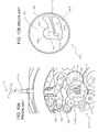
- a time difference correction attached timepiece of recent times in a time difference correction attached timepiece of this kind is provided with a structure as shown by, for example, Fig. 10A to minimize a number of parts and achieve small-sized formation. That is, a time difference correction attached timepiece 101 includes an auxiliary hour wheel 120 for indicating time at a land spot having a time difference such as a specific location of a foreign country in addition to a normal hour indicator (hour wheel) (not illustrated), a minute indicator 112 and a second indicator (not illustrated) for operating hands of a normal time indicating mechanism having an hour hand, a minute hand and a second hand separately from the normal hour indicator (hour wheel).
- the auxiliary hour wheel 120 includes a first auxiliary hour wheel portion 130 having a pinion portion 132 in a mode of a finger wheel, and a second auxiliary hour wheel portion 150 engaged with the first auxiliary wheel portion 130 to form a slip mechanism attached wheel structure 140 in cooperation with the first auxiliary hour wheel portion 130 in order to minimize a number of parts and achieve small-sized formation.
- the second auxiliary hour wheel portion 150 is brought in mesh with a minute wheel 114.
- the second auxiliary hour wheel portion 150 constituting the auxiliary hour wheel 120 of the background art includes a circular plate-like main body portion 152 and a wheel portion 156 at an outer periphery of the circular plate-like main body portion 152 as enlarged to be shown in Fig. 10B in addition to Fig. 10A.
- the circular plate-like main body portion 152 adopts a mode of a jumper attached wheel having a hole 160 and a jumper portion 170.
- the hole 160 of the circular plate-like main body portion 152 includes a center hole portion 161 loosely fitted with the finger wheel or the pinion portion 132 of the first auxiliary hour wheel portion 130 and a middle hole portion 164 extended between a one side opening 162 of the center hole portion 161 and a vicinity of an outer peripheral edge portion 163.
- the jumper portion 170 includes an elastic arm portion 172 connected to a peripheral wall portion of the middle hole portion 164 by a base end 171 and extended from the base end 171 to the one side opening 162 of the center hole portion 161, and a jump restraining finger portion 175 engaged with the finger wheel 132 at a portion of the elastic arm portion 172 facing the one side 162 of the center hole portion 161.
- the elastic arm portion 172 is operated as a spring.
- the middle hole portion 164 of the hole 160 of the circular plate-like main body portion 152 permits elastic deformation of the elastic arm portion 172 of the jumper portion 170 when the jump restraining finger portion 175 of the jumper portion 170 is engaged and detached to and from a finger portion 134 of the finger wheel 132.
- the jumper portion 170 forms a slip mechanism 141 of a timepiece in cooperation with the finger wheel 132.
- the slip mechanism attached wheel structure 140 includes the jumper attached wheel 150 and the finger wheel 132.
- rotation of the minute indicator 112 is transmitted to the wheel portion 156 of an outer periphery of the circular plate-like main body portion 152 of a second auxiliary hour wheel portion 150 of the auxiliary hour wheel 120 by way of the minute wheel 114.
- the second auxiliary hour wheel portion 150 is driven to rotate
- an engagement between the jumper portion 170 of the slip mechanism 141 and the finger wheel 132 is maintained
- the first auxiliary hour wheel portion 130 is rotated in accordance with rotation of the second auxiliary hour wheel portion 150, and an auxiliary hour hand (not illustrated) attached to the first auxiliary hour wheel portion 130 is operated.
- a winding stem 103 is set to a pull out position for correcting a time difference, the winding stem 103 is rotated in A1 direction or A2 direction around a rotation center axis line A, thereby, the first auxiliary hour wheel portion 130 is rotated in E1 direction or E2 direction by way of a first and a second calendar corrector transmission wheel 181, 182 and a first and a second hour corrector setting transmission wheel 185, 186, and the auxiliary hour hand attached to the first auxiliary hour wheel portion 130 is rotated to a predetermined time indicating position.
- the winding stem 103 is disposed at the pull out position for correcting the time difference, depending on rotation of the winding stem 103, normal indicators (normal hour indicator, minute indicator 112 and second indicator) are not rotated.
- the first auxiliary hour wheel portion 130 is engaged with the second auxiliary hour wheel portion (jumper attached wheel) 150 by way of the slip mechanism 141 and the second auxiliary hour wheel portion 150 is engaged with a speed increasing train wheel of the minute indicator 112 or the like by way of the minute wheel 114, and therefore, the jump restraining finger portion 175 of the jumper portion 170 constituting a portion of the slip mechanism 141 of the second auxiliary hour wheel portion is jumped relative to the finger portion (tooth portion) of the pinion portion 132 constituting other portion of the slip mechanism 1401 of the first auxiliary hour wheel portion 130 to produce a slip between the first and the second auxiliary hour wheel portions 130, 150, and therefore, in correcting the time difference, indication of the time indicating hand in the normal hand operating state is maintained as it
- the jumper portion 170 constituting the slip mechanism 141 of the background art is constituted by a mode of a cantilever and the elastic arm portion 172 is extended substantially linearly in a direction substantially in parallel with a tangential direction of the finger wheel 132 at a portion at which the jump restraining finger portion 175 is engaged with the finger wheel (pinion portion) 132. Therefore, when a direction of rotating the finger wheel 132 differs, a force required for rotating the finger wheel 132 differs.
- a rotation restraining force of the jumper portion 170 against rotation of the finger wheel 132 differs by a case of rotating the jump restraining finger portion 175 in E2 direction to press to a front end side of the elastic arm portion 172 of the jumper portion 170 by the finger portion of the finger wheel 132 as shown by Fig. 11A and a case of rotating the jump restraining finger portion 175 in E1 direction to press to the base end side of the elastic arm portion 172 by the finger portion of the finger wheel 132 as shown by Fig. 11B (a side of Fig. 11B becomes larger). Therefore, in correcting the time difference, a torque required for correcting the time difference differs by a direction of rotating the winding stem 103, which gives a strange feeling to a user.
- a diameter of the jumper attached wheel 150 constituting the slip mechanism attached wheel structure 140 is as small as or several mm, and therefore, a length of the elastic arm portion (spring portion) 172 of the jumper portion 170 is also restricted to be shortened and there is a concern of destructing the base portion or the like of the elastic arm portion 172 by applying a large stress to the base portion or the like of the elastic arm portion 172 to which a bending stress is concentrated.
- a jumper attached wheel for a timepiece of the invention is a jumper attached wheel for a timepiece including a circular plate-like main body portion including a jumper portion comprising a hole comprising a center hole portion to which a finger wheel is loosely fitted and a middle hole portion expanded between one side of the center hole portion and a vicinity of an outer peripheral edge portion, an elastic arm portion connected to a peripheral wall portion of the middle hole portion at a base end thereof and extended from the base end to the one side of the center hole portion and a jump restraining finger portion engaged with the finger wheel at a portion of the elastic arm portion facing the one side of the center hole portion, and a wheel portion at an outer periphery of the circular plate-like main body portion, wherein a slip mechanism attached wheel structure of the timepiece is formed in cooperation with the finger wheel, and further comprising guiding means for guiding the jump restraining finger portion in a diameter direction of the finger wheel when the elastic arm portion is elastically deformed in accord
- the jumper attached wheel for a timepiece of the invention is "the jumper attached wheel for a timepiece forming the slip mechanism attached wheel structure of a timepiece in cooperation with the finger wheel, the jumper attached wheel is provided with the guiding means for guiding the jump restraining finger portion of the jumper portion (finger portion of the jumper portion) when the elastic arm portion of the jumper portion is elastically deformed in accordance with the rotation of the finger wheel in the diameter direction of the finger wheel", and therefore, even when a restraining force is minimized by comparatively reducing a rigidity of the elastic arm portion of the jumper portion, regardless of a direction of rotating the finger wheel, the jump restraining finger portion of the jumper portion is moved in the diameter direction of the finger wheel, and therefore, regardless of the direction of rotating the finger wheel, actually the same magnitude of the restraining force can be exerted. Therefore, according to the jumper attached wheel for a timepiece of the invention, also a torque to be applied by a user is to the same degree in the both
- a way of guiding by the guiding means can be specified, and therefore, alsoengagementormeshing of the jump restraining finger portion of the jumper portion and the finger portion of the finger wheel and a releasing operation thereof (for example, timing) can be set as desired.
- a direction in which the jump restraining finger portion of the jumper portion can be moved is restrained by the guiding means, and therefore, even when the elastic arm portion is made to be easy to be flexed, there is not a concern of displacing the jump restraining finger portion and the elastic arm portion in a direction orthogonal to the movable direction of the jump restraining finger portion to be brought into contact with a peripheral wall of a hole portion. Therefore, the movable arm portion can be made to be slender or long or slender and long, and therefore, stress concentration on the base portion of the movable arm portion can be minimized and a concern of destructing the jumper portion is inconsiderable.
- the jumper portion when the jumper portion is elastically deformed in accordance with the rotation of the finger wheel, the jumper portion can firmly be guided linearly by the engaging guide portion at the engaged portion, and therefore, an operation of restraining jumping by the jumper portion can stably be carried out.
- the elastic arm portion includes the engaged portion on a front end side of the jump restraining finger portion.
- the jumper portion includes a branch portion branched from the elastic arm portion at a portion of a middle of the base end portion and the jump restraining finger portion of the elastic arm portion, and the branch portion includes the engaged portion.
- the elastic arm portion includes a pair of arm portions connected by the jump restraining finger portion.
- the pair of arm portions of the jump restraining arm portion can similarly contribute to the jump restraining operation regardless of the direction of rotating the finger wheel, and therefore, a similar restraining force can be exerted regardless of the direction of rotating the finger wheel.
- the guiding means includes a pair of engaging guide portions formed at the circular plate-like main body portion at a portion of a peripheral edge of the hole, and engaged portions formed at regions of the respective arm portions of the jumper portion facing the engaging guide portions and engaged with the engaging guide portions in accordance with an elastic deformation of the elastic arm portion in accordance with rotation of the finger wheel to be linearly guided thereby.
- the jumper portion when the pair of arm portions of the elastic arm portion of the jumper portion is elastically deformed in accordance with the rotation of the finger wheel, the jumper portion can firmly be guided linearly by the engaging guide portion at the engaged portion, and therefore, the operation of restraining jumping by the jumper portion can stably be carried out.
- the guiding means includes an engaging guide portion formed at the circular plate-like main body portion at a portion of a peripheral edge of the hole facing aback face of the jump restraining finger portion, and an engaged portion formed at a region of the elastic arm portion of the jumper portion opposed to the engaging guide portion and engaged with the engaging guide portion in accordance with an elastic deformation of the elastic arm portion in accordance with rotation of the finger wheel to be linearly guided thereby.
- the jump restraining finger portion of the jumper portion can linearly be guided similar to the engaged portion, and therefore, regardless of the deformation of the elastic arm portion, the operation of restraining jumping of the jumper portion can stably be carried out.
- the engaging guide portion is a recessed portion
- the engaged portion comprises a projected portion engaged with the recessed portion
- the engaging guide portion may be constituted by a projected portion and the engaged portion may be constituted by a recessed portion.
- a slip mechanism attached wheel structure of a timepiece of the invention includes the jumper attached wheel for a timepiece and the finger wheel as described above.
- the slip mechanism is constituted by the jumper portion and the finger wheel of the jumper attached wheel.
- a time correcting structure of a timepiece of the invention is a timepiece correcting structure of a timepiece including the slip mechanism attached wheel structure of a timepiece as described above, in which the jumper attached wheel is an hour wheel.
- a time difference correction attached timepiece of the invention typically includes the time correcting structure as mentioned above.
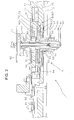
- Fig. 1 and Fig. 2 show a time difference correction attached timepiece 1 according to a preferable example of the invention.
- the time difference correction attached timepiece 1 includes a time difference correcting structure 2 of a preferable example of the invention including a slip mechanism attached wheel structure 3 of a preferable example of the invention including a jumper attached wheel 70 of a preferable first example of the invention.
- the time difference correction attached timepiece 1 includes an auxiliary hour indicator 60 as an auxiliary hour wheel attached with a time difference hour hand 61 for indicating an hour having a time difference in addition to an hour indicator 20, a minute indicator 30 and a second indicator 40 attached with a normal or inherent hour hand 21, a minute hand 31 and a second hand 41.
- "Main" means a portion related to normal or inherent time indication, for example, normal or inherent hour hand 21 is also referred to as the main hour hand 21 as follows.
- numeral 10 designates a main plate
- numerals 11, 12 designate bridges of train wheel bridges and the like
- numeral 13 designates a date indicator jumper or a setting lever jumper.
- the second wheel 40 is driven to rotate at a predetermined speed from a train wheel drive mechanism (not illustrated) at a second wheel 42, and rotates a minute wheel 32 of the minute indicator 30 by way of a transmission wheel (not illustrated) such as a third wheel & pinion at a second pinion 43.
- the minute indicator 30 is slippingly engaged with a barrel portion or a shaft portion 33 of the minute wheel 32 that rotates a minute wheel 51 of a minute wheel & pinion 50 by way of a minute pinion 34, and the minute wheel & pinion 50 rotates the hour indicator (hour wheel) 20 brought in mesh therewith by way of a minute pinion (not illustrated).
- the second hand 41, the minute hand 31 and the main hour hand 21 are rotated to indicate normal current time.
- an auxiliary hour wheel or the auxiliary hour indicator 60 of the time difference correction attached timepiece 1 comprises three portions 60A, 60B1, 60B2, and the first portion 60A adopts a mode of the jumper attached wheel 70.
- the second portion 60B1 is in a mode of a finger wheel or pinion 62 having a small diameter and is slidingly rotatably fitted to the barrel portion or the shaft portion 33 of the minute indicator 30.
- the finger wheel 62 includes 12 pieces of fingers 67 (Fig. 1) having the same size and shape at equal intervals.
- the third portion 60B2 includes a barrel portion 65 including a hole portion 64 to which a hollow shaft portion 63 of the finger wheel 62 is fitted to be attached and a wheel portion 66 integral therewith.
- the second portion 60B1 and the third portion 60B2 constitute an integral auxiliary hour wheel main body portion 60B as a whole.
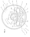
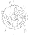
- the jumper attached wheel 70 includes a circular plate-like main body portion 71 and a spur wheel portion 72 at an outer periphery of the main body portion 71 as is known from a plan view of Fig. 3 enlarging to show only the wheel 70 in addition to a sectional view of Fig. 2.
- the circular plate-like main body portion 71 includes a large hole 73 and a jumper portion 80 extended to inside of the hole 73.
- the hole 73 includes a center hole portion 74, and a middle hole portion 75 expanded between a one side opening 74A of the center hole portion 74 and an outer peripheral edge portion 71A of the circular plate-like main body portion 71.
- the middle hole portion 75 includes a pair of recessed portions 76A, 76B (designated by notation "76" when generally referred to or when not differentiated from each other) as engaging guide portions symmetrically on both sides of the center portion 74.
- Inner side faces 77A, 77B (designated by notation "77” when generally referred to or when not differentiated from each other) of the recessed portions 76A, 76B are constituted by substantially shapes of linear lines in parallel with each other.
- the center hole portion 74 is loosely fitted with the finger wheel or the pinion 62 constituting the second portion 60B2 constituting the auxiliary hour wheel main body portion 60B (refer to Fig. 1 and Fig. 4).
- the center hole portion 74 includes a peripheral face 74B in a shape of a circular arc extended over a range larger than 180 degrees, and an opening portion of the circular arc constitutes the opening portion 74A of the center hole portion 74.
- the finger wheel or the pinion 62 loosely fitted to the center hole portion 74 is substantially brought into inward contact with the circular arc shape peripheral face 74B and is projected to inside of the middle hole portion 75 from the center hole portion 74 at the opening portion 74A.
- the middle hole portion 75 is continuous to the center hole portion 74 at the one side opening 74A of the center hole portion 74 and is expanded between the opening 74A and a vicinity of the outer peripheral edge portion 71A of the circular plate shape main body portion 71.
- a jumper portion 80 includes an elastic arm portion 81 and a jump restraining finger portion 82, and the elastic arm portion 81 comprises a pair of elastic arm portions 81A, 81B (designated by notation "81" when generally referred to or when not differentiated from each other).
- the elastic arm portions 81 or the respective elastic arm portions 81A, 81B are continuous to the peripheral wall portion (outer peripheral edge portion of the plate-like main body portion 71) 71A of the middle hole portion 75 at base ends 83A, 83B (designated by notation "83" when generally referred to or when not differentiated from each other), extended from the base ends 83A, 83B to vicinities of the opening 74A of the center hole portion 74, and integrally continuous to the jump restraining finger portion 82 at extended ends 84A, 84B (designated by notation "84" when generally referred to or when not differentiated from each other). Therefore, the jump restraining finger portion 82 is disposed at a location facing the opening 74A.
- the elastic arm portions 81A, 81B are provided with a slender shape (having small width and long length) smoothly bent in an S-like shape (or a shape symmetrical therewith, that is, an inverse S-like shape) to avoid a stress (for example, about several hundreds Pa at maximum) from being concentrated on the base end portion or the like, and include projected portions 85A, 85B (designated by notation "85" when generally referred to or when not differentiated from each other) at positions of the middle hole portion 75 fitted to guide recessed portions 76A, 76B.
- the engaged projected portions 85A, 85B are proximate to or brought into sliding contact with the inner side faces 77A, 77B of the engaging guide recessed portions 76A, 76B respectively at inner side edges 86A, 86B (designated by notation "86" when generally referred to or when not differentiated from each other), and are movable in D1, D2 directions at insides of the engaging guide recessed portion 76A, 76B.
- the pairs of engaging guide recessed portions 76A, 76B and engaged projected portions 85A, 85B permit a displacement of the jump restraining finger portion 82 actually only in directions D1, D2 by which the jump restraining finger portion 82 is made to be proximate to or separated from a center C of the center circular shape hole portion 74, and actually prohibit a displacement of the jump restraining finger portion 82 in directions intersecting with the directions D1, D2.
- guiding means 79 comprises the engaging guide recessed portion 76 and the engaged projected portion 85.
- the directions D1, D2 of displacing the jump restraining finger portion 82 actually coincide with a radius direction of the finger wheel 62.
- the elastic arm portions 81A, 81B are provided with shapes and sizes so as not to be brought into contact with a peripheral wall 78 of the middle hole portion 75 in elastic deformation thereof in accordance with the displacement of the jump restraining finger portion 82 in D1, D2 directions.
- the middle hole portion 75 includes the peripheral wall 78 in a shape by which a clearance actually remains between the peripheral wall 78 and the respective portions (excluding the engaged projected portions 85A, 85B) of the elastic arm portions 81A, 81B when the elastic arm portions 81A, 81B are elastically deformed in accordance with the displacement of the jump restraining finger portion 82 in D1, D2 directions.
- the jumper attached wheel 70 is provided with a diameter of, for example, several mm (however, may be larger or smaller) and a width of the elastic arm portion 81 is, for example, about 0.1 through 0.3 mm (however, may be larger or smaller).
- a jumper attached wheel 70 is preferably formed by UV-LIGA.
- the jumper attached wheel 70 may be fabricated by pressing or the like instead of UV-LIGA.
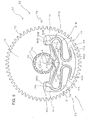
- the jump restraining finger portion 82 of the jumper portion 80 is engaged between two contiguous finger portions 67, 67 of the finger wheel 62.
- the jumper portion 80 may be brought into a state actually the same as a state of not being exerted with an external force as in Fig. 3, typically, the jumper portion 80 adopts a state in which the jump restraining finger portion 82 is displaced slightly in D2 direction such that the jumper portion 80 restrains rotation of the finger wheel 62.
- the slip mechanism attached wheel structure 3 comprises the j*umper attached wheel 70 and the finger wheel 62, when the jumper attached wheel 70 constitutes a drive side and the finger wheel 62 constitutes a driven side, a slipping operation is not produced in the slip mechanism attached wheel structure 3.
- the slip mechanism 4 is formed by the jumper portion 80 of the jumper attached wheel 70 and the finger wheel 62.
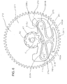
- the elastic arm portions 81A, 81B of the jumper attached wheel 70 are elastically deformed from the state S1 indicated by the imaginary line to the state S2 indicated by the bold line.
- the jump restraining finger portion 82 is restrained by the engaging guide recessed portions 76A, 76B and the engaged projected portions 85A, 85B to be displaced in D2 direction.
- the finger wheel 62 is rotated while elastically deforming the elastic arm portions 81A, 81B of the jumper portion 80 to move back the jump restraining finger portion 82 in D2 direction until a front end of the finger portion 67 on a downstream side in a rotational direction of the contiguous finger portions 67, 67 of the finger wheel 62 rides over a front end of the jump restraining finger portion 82, when the front end portion of the finger portion 67A of the finger wheel 62 rides over the front end portion of the jump restraining finger portion 82 of the jumper portion 80, the finger wheel 62 is' rotated further in E1 direction by elastic recovery forces of the elastic arm portions 81A, 81B of the jumper portion 80, and the jumper portion 80 and the finger wheel 62 reach the successive stable state S1.
- the jump restraining finger portion 82 and the finger wheel 62 of the jumper portion 80 may reach the successive stable state S1 in accordance with rotation of the finger wheel 62 further in E2 direction so far as the jump restraining finger portion 82 and the finger wheel 62 can be maintained to the stable state S1 by a restraining force of the jumper portion 80.
- the above-described operation of the jump restraining finger portion 82 can be carried out substantially similarly even when the finger wheel 62 is rotated in E1 direction or E2 direction. Further, by selecting the shapes of the engaging guide recessed portion 76 and the engaged projected portion 85 constituting guiding means as desired, the engagement between the finger portions 67, 67 of the finger wheel 62 and the jump restraining finger portion 82 and a timing of releasing the engagement can be set (selected).
- a jumper attached wheel 270 of the comparative example shown in Fig. 6 is constituted similar to the jumper attached wheel 70 shown in Fig. 3 through Fig. 5 except that arm portions 281A, 281B of an elastic arm portion 281 of a jumper portion 280 are devoid of the engaged projected portions 85A, 85B as in the arm portions 81A, 81B of the elastic arm portion 81 of the jumper portion 80, and portions in correspondence with the projected portions are constituted by outer surfaces 281A, 281B smoothly bent to constitute slender arm portions in an S-like shape similar to other portions.
- the jumper attached wheel 270 of the comparative example for example, when the finger wheel 62 is rotated in E2 direction, a finger portion 67C disposed on an upstream side of a jump restraining finger portion 282 of the jumper portion 280 in direction E2 of rotating the finger wheel 62 in the finger portions 67 of the finger wheel 62 presses the jump restraining finger portion 282 in a peripheral direction F. Therefore, at base end portions 283A, 283B of the elastic arm portions 281A, 281B, the S-like shape elastic arm portions 281A, 281B of the jumper portion 280 supported by a peripheral wall portion 271A are pivoted by receiving a torque in G direction around the base end portions 283A, 283B.
- the elastic arm portions 281A, 281B are provided with the S-like shape to avoid a stress from being concentrated on a specific portion, and therefore, the elastic arm portions 281A, 281B are comparatively considerably pivoted while being deformed respectively, and as exemplified in Fig. 6, a portion H, J or the like disposed at a front edge in a direction of pivoting the elastic arm portion 281A, 281B is brought into contact to be pressed to a facing portion 278H, 278J or the like of the peripheral wall 278 of a middle hole portion 275.
- the jumper attached wheel 70 of the example of the invention since the engaging guide portions 76A, 76B and the engaged portions 85A, 85B as the guiding means 79 are provided, although the elastic arm portions 81A, 81B of the jumper portion 80 are constituted by shapes and sizes easy to be elastically deformed comparatively, the jumper portion 80 is guided by the guiding means and can firmly be displaced in D1, D2 directions, and therefore, an operation of restraining jumping of the jumper portion 80 can stably be carried out.
- respective portions including the elastic arm portions 81A, 81B and the hole portion 73 of the jumper portion 80 are provided with shapes in mirror symmetry with regard to an imaginary center line K connecting the front end of the jump restraining finger portion 82 disposed at the stable position and the center C of the center hole portion 74, and therefore, regardless of the rotational directions E1, E2 of the finger wheel 62, the jumper portion 80 can similarly be operated to restrain jumping.
- the jumper attached wheel 70 constituting the portion B1 of the auxiliary hour wheel 60 is brought in mesh with a time difference correcting pinion portion 52 of the minute wheel 50 at the wheel portion 72.
- the time difference correcting structure 2 as the time correcting structure of the time difference correction attached timepiece 1 includes the first and the second calendar corrector setting transmission wheels 91 and 92 meshing with each other as well as the first and the second time corrector setting transmission wheels 93 and 94 in addition to the auxiliary hour wheel 60 of the mode of the slip mechanism attached wheel structure 3.
- the first calendar corrector setting transmission wheel 91 is brought in mesh with a setting wheel 15 when the winding stem 14 is pulled in M direction to be set to a time difference correcting position M1 and is rotated by way of a clutch wheel 16 and the setting wheel 15 when the winding stem 14 is rotated in A1 or A2 direction around a center axis line A.
- the second hour corrector setting transmission wheel 94 is brought in mesh with the wheel portion 66 of the main body portion 60B of the auxiliary hour wheel 60 to transmit rotation in A1 or A2 direction of the windingstem 14 to the main body portion 60B of the auxiliary hour wheel 60 to rotate the auxiliary hour wheel 60 in E1 or E2 direction.
- the barrel portion 65 of the auxiliary hour wheel main body 60B is rotated in E1 or E2 direction in accordance with rotation A1 or A2 direction of the winding stem 14 set to the time difference correcting position M1 and the auxiliary hour hand or the time difference hand 61 is rotated in E1 or E2 direction to be set to time shifted by an amount of the time difference.
- the pinion portion or the finger wheel portion 62 of the auxiliary hour wheel main body 60B is also rotated in E1 or E2 direction
- the jumper attached wheel 70 is connected to a comparatively high load system by way of the time difference correcting pinion portion 52 of the minute wheel 50, and therefore, the jumper attached wheel 70 is not rotated by rotating the finger wheel 62.
- the elastic arm portion 81 of the jumper portion 80 of the jumper attached wheel 70 is guided by the guiding means 79 in accordance with rotation of the finger wheel portion 62 to be displaced in D1, D2 direction, and therefore, the jump restraining finger portion 82 can stably be displaced in D2, D2 direction. Therefore, not only the time difference correcting operation can smoothly be carried out but also the time difference correcting operation does not hamper rotation of the hour indicator 20 or the minute indicator 30 or the second indicator 40 brought into the normal hand operating state.
- the jumper portion 80 of the jumper attached wheel 70 is provided with the shape in mirror symmetry with regard to the imaginary center line K, and therefore, regardless of rotational directions E1, E2 of the finger wheel 62, the finger wheel 62 can be rotated in a state of having the same rotational load, and therefore, the load applied on the winding stem 14 stays the same when the winding stem 14 is turned in a direction of increasing a time difference to be indicated and when the winding stem 14 is turned in a direction of reducing the time difference to be indicated, and therefore, also a torque to be applied by a user stays the same in the two directions, and therefore, the user can correct the time difference in either of directions without a strange feeling.
- Fig. 7 shows a jumper attached wheel A70 according to a second example of the invention.
- an element (portion, position or the like) similar to an element (portion, position or the like) of the jumper attached wheel 70 of the first example shown in Fig. 3 is attached with notation "A" at the front of the reference numeral.
- an elastic arm portion A81 constituting a jumper portion A80 includes a pair of elastic arm portions A81A, A81B and includes a jump restraining finger portion A82 along a center line K of symmetry between front end portions A84A, A84B.
- one guiding means A79 is formed on a back side of the jump restraining finger portion A82.
- the elastic arm portions A81A, A81B are formed by a shape of a circular arc in a state of surrounding the jump restraining finger portion A82 such that the jump restraining finger portion A82 is disposed on an inner peripheral side thereof instead of being formed in an S-like shape on the back side of the jump restraining finger portion A82.
- a middle hole portion A75 connected to an opening A74A of a center hole portion A74 to which a finger wheel is loosely fitted in a hole A73 includes portions A75CA, A75CB to actually surround the center hole portion 74 as a whole.
- the elastic arm portions A81A, A81B are connected not to an outer peripheral wall portion A71A per se of a circular plate-like main body portion A71 of the jumper attached wheel A70 extended in a circular arc shape but to both side edges of extended portions A71A1 projected to an inner side in a radius direction from the outer peripheral portion A71A at base end portions A83A, A83B.
- the guiding means 79 comprises an engaging guide recessed portion A76 formed at a peripheral wall A78 of the center hole portion A75 along the center of symmetry K, and an engaged projected portion A85 fitted to the recessed portion A76 displaceably in D1, D2 directions.
- a width of the engaged projected portion A85 is substantially the same as a width of the engaging guide recessed portion A76, and the engaged projected portion A85 is substantially brought into sliding contact with both side edges of the engaging guide recessed portion A76 at both side edges thereof.
- both of the engaging guide recessed portion A76 and the engaged projected portion A85 are provided with shapes in mirror symmetry with regard to the center line of symmetry K.
- the engaging guide recessed portion A76 includes projected portions at both side walls thereof to be able to engage with the engaged projected portion A85 by a sufficient length. However, the projected portions may not be provided.
- the guiding means A79 restrains a direction of displacing the jump restraining finger portion A82 of the jumper portion A80 actually in D1, D2 directions, and therefore, even when the elastic arm portions A81A, A81B are constituted by a shape or a state of being elastic and flexible (easy to be flexed) as a whole, jump restraining operation can stably be carried out without bringing the elastic arm portions A81A, A81B into contact with the peripheral wall A78 of the middle recessed portion A75.
- the elastic arm portion constituting the jumper portion may be constituted by one arm portion instead of comprising the pair of arm portions.
- a member similar to the element of the jumper attached wheel 70 of Fig. 3 has a prefix "B" on the corresponding reference numeral.
- an elastic arm portion B81 constituting the jumper portion B80 comprises the single elastic arm portion B81 and in this example, the elastic arm portion B81 is provided with a shape of being meandered in a zigzag shape.
- the elastic arm portion B81 is connected to a peripheral wall portion of a center hole portion B75 at a base end B83 and includes an engaged projected portion B85 in a circular shape at a jump restraining arm portion front end B87.
- the arm portion front end portion B87 comprises a front end arm portion B88 extended in K direction, and an engaged projected portion B85 in a circular shape formed at a front end of the front end arm portion B88.
- the jumper portion B80 includes a jump restraining finger portion B82 at a portion proximate to the front end B87 of the arm portion meandering in the zigzag shape of the jump restraining arm portion B81 and facing a center of an opening portion B74 of a center hole portion B73.
- the zigzag shape (a number of times of meandering of the zigzag or shapes or lengths of respective meandering portions of forming the meandering or the like) of the elastic arm portion B81 may be constituted by any shape so far as the shape can provide the base end B83 with a sufficient flexibility (easy to be flexed) for the jump restraining finger portion B82.
- the elastic arm portion B81 includes the engaged projected portion B85 on a front end side of the jump restraining portion B82, and a circular plate-like main body portion B71 includes an engaging guide recessed portion B76 extended in K direction at a portion of the middle hole portion B75 in correspondence with the engaged projected portion B85.
- the engaging guide recessed portion B76 is provided with a width similar to a diameter of the engaged projected portion B85. Therefore, the engaged projectedportion B85 is brought into sliding contact with both side edges B76C, B76D of the engaging guide recessed portion B76 at both side edges B86C, B86D thereof to be guided by the two side edges B76C, B76D in D1, D2 directions.
- guiding means B79 comprises the engaging guide recessed portion B76 and the engaged projected portion B85.
- the jumper attached wheel B70 constituted as described above, a movement of the front end side portion of the elastic arm portion B81 is restrained in D1, D2 directions by the guiding means B79, and therefore, the jump restraining finger portion B82 can actually be displaced only in D1, D2 directions.
- the jump restraining finger portion B82 is displaced by fingers 67, 67 of the finger wheel 62 by rotating the finger wheel 62, there is not a concern of bringing the elastic arm portion B81 into contact with the peripheral wall B78 of the middle hole portion B75, and an operation of restraining jumping by the jumper portion B80 can stably be carried out.
- the elastic arm portion comprises the single arm portion, similar to a case of comprising the pair of arm portions (refer to Fig. 3 and Fig. 7), the elastic arm portion may comprise the arm portion in the circular arc shape considerably rounded on the back side of the center hole portion instead of the arm portion in the zigzag shape.
- a a member similar to the element of the jumper attached wheel B70 of Fig. 8 is attached with a prefix "C" instead of the prefix "B".
- an elastic arm portion C81 constituting a jumper portion C80 comprises a single elastic arm portion C81, according to the example, the elastic arm portion C81 is provided with a circular arc shape extended over an angle range equal to or larger than 180 degrees.
- the elastic armportion C81 is connected to a projected portion C71A1 of a peripheral wall portion of a middle hole portion C75 at a base end C83 disposed on a back side of a center hole portion C74, and includes an engaged projected portion C85 in a circular shape at a jump restraining arm portion front end C87.
- the center hole portion C75 includes a circular arc shape portion C75C extended in a circular arc shape to surround the center hole portion C74 over a range of about 180 degrees or more as a whole.
- the arm portion front end portion C87 comprises a front end arm portion C88 extended in D1, D2 directions, and the engaged projected portion C85 in a circular shape formed at a front end of the front end arm portion C88.
- the jumper portion C80 includes an arm portion C89 branched at a vicinity of the front end portion C88 of the jump restraining arm portion C81 and extended to a center of an opening portion C74A of the center hole portion C74, and includes a jump restraining finger portion C82 at the arm portion C89.
- the front end portion C87 can be regarded as a branch portion instead of regarding the arm portion C89 of the elastic arm portion C81 as the branch portion.
- the circular arc portion of the elastic arm portion C81 may be extended over an angle range far larger than 180 degrees, or may be about 180 degrees, or over an angle range considerably smaller than 180 degrees at inside of a main body portion C75D and the circular arc shape portion C75C of the middle hole portion 75 so far as the jump restraining finger portion C82 can provide a sufficient flexibility or easiness of bending to the base end C83.
- the elastic arm portion C81 is typically provided with substantially similar width and a similar shape such that a total thereof can uniformly be flexed, when desired, a width of the base end side may be wide.
- a circular plate shape main body portion C71 includes an engaging guide recessed portion C76 extended in D1, D2 directions at a portion of the middle hole portion C75 in correspondence with the engaged projected portion C85.
- a width of the engaging guide recessed portion C76 is sufficiently similar to a diameter of the engaged projected portion C85. Therefore, the engaged projected portion C85 is brought into sliding contact with both side edges C76C, C76D at both side edges C86C, C86D to be guided in D1, D2 directions by the both side edges C76C, C76D.
- guiding means C79 comprises the engaging guide recessed portion C76 and the engaged projected portion C85.
- the jumper attached wheel C70 constituted as described above, a movement of a front end side portion of the elastic arm portion C81 is restricted in D1, D2 directions by the guiding means C79, and therefore, the jump restraining finger portion C82 can be displaced actually only in D1, D2 directions.
- the jump restraining finger portion C82 is displaced by the fingers 67, 67 of the finger wheel 62 by rotating the finger wheel 62, there is not a concern of bringing the elastic arm portion C81 into contact with a peripheral wall C78 of the middle hole portion C75, and an operation of restraining jumping by the jumper portion C80 can stably be carried out.
- the jumper attached wheel of the invention may be used in other portions of the timepiece.
Landscapes
- Physics & Mathematics (AREA)
- General Physics & Mathematics (AREA)
- Electromechanical Clocks (AREA)
- Gears, Cams (AREA)
Applications Claiming Priority (1)
| Application Number | Priority Date | Filing Date | Title |
|---|---|---|---|
| JP2006232190A JP2008058012A (ja) | 2006-08-29 | 2006-08-29 | 時計用ジャンパ付き歯車、時計のスリップ機構付き歯車構造体、時刻修正構造、及び時差修正付き時計 |
Publications (2)
| Publication Number | Publication Date |
|---|---|
| EP1895370A2 true EP1895370A2 (de) | 2008-03-05 |
| EP1895370A3 EP1895370A3 (de) | 2009-01-21 |
Family
ID=38728879
Family Applications (1)
| Application Number | Title | Priority Date | Filing Date |
|---|---|---|---|
| EP07253359A Withdrawn EP1895370A3 (de) | 2006-08-29 | 2007-08-24 | Rad mit Hebelfeder für eine Uhr, Radstruktur mit Rutschmechanismus für eine Uhr, Zeitkorrekturstruktur und Uhr mit Zeitdifferenzkorrektur |
Country Status (2)
| Country | Link |
|---|---|
| EP (1) | EP1895370A3 (de) |
| JP (1) | JP2008058012A (de) |
Cited By (7)
| Publication number | Priority date | Publication date | Assignee | Title |
|---|---|---|---|---|
| CH710467A1 (fr) * | 2014-12-12 | 2016-06-15 | Richemont Int Sa | Roue pour mobile à friction de mécanisme horloger et mobile à friction correspondant. |
| CN107870549A (zh) * | 2016-09-23 | 2018-04-03 | 宝齐莱股份公司 | 陀飞轮和带陀飞轮的表 |
| CN108614406A (zh) * | 2016-12-13 | 2018-10-02 | 精工爱普生株式会社 | 钟表用机芯、机械式钟表以及棘爪杆的卡合解除方法 |
| EP3772673A1 (de) * | 2019-08-08 | 2021-02-10 | ETA SA Manufacture Horlogère Suisse | Indexierungselement für uhren |
| US20220091561A1 (en) * | 2019-01-07 | 2022-03-24 | Citizen Watch Co., Ltd. | Time difference correction mechanism and clock with time difference correction mechanism |
| EP4180882A1 (de) * | 2021-11-12 | 2023-05-17 | Soprod SA | Indexierungsvorrichtung für einen uhrwerk |
| EP4170434B1 (de) * | 2021-10-25 | 2025-10-01 | Comadur SA | Verfahren zur dekoration eines substrats |
Families Citing this family (4)
| Publication number | Priority date | Publication date | Assignee | Title |
|---|---|---|---|---|
| EP2362276B1 (de) * | 2010-02-25 | 2012-10-31 | Montres Breguet SA | Programmierbares und umprogrammierbares mechanisches Speicherrad für Uhr |
| EP2362277B1 (de) * | 2010-02-25 | 2012-10-31 | Montres Breguet SA | Zeitzone auf Wunsch auf den Hauptzeigern einer Uhr |
| CH713288A1 (fr) * | 2016-12-23 | 2018-06-29 | Sa De La Manufacture Dhorlogerie Audemars Piguet & Cie | Composant monolithique flexible pour pièce d'horlogerie. |
| NL2023420B1 (en) * | 2019-07-02 | 2021-02-02 | Flexous Mech Ip B V | Watch or timepiece |
Family Cites Families (2)
| Publication number | Priority date | Publication date | Assignee | Title |
|---|---|---|---|---|
| JPH07111463B2 (ja) * | 1990-01-18 | 1995-11-29 | セイコーエプソン株式会社 | 時計の時刻修正構造 |
| JPH0990061A (ja) * | 1995-09-27 | 1997-04-04 | Citizen Watch Co Ltd | 時差修正付時計 |
-
2006
- 2006-08-29 JP JP2006232190A patent/JP2008058012A/ja active Pending
-
2007
- 2007-08-24 EP EP07253359A patent/EP1895370A3/de not_active Withdrawn
Cited By (12)
| Publication number | Priority date | Publication date | Assignee | Title |
|---|---|---|---|---|
| CH710467A1 (fr) * | 2014-12-12 | 2016-06-15 | Richemont Int Sa | Roue pour mobile à friction de mécanisme horloger et mobile à friction correspondant. |
| CN107870549A (zh) * | 2016-09-23 | 2018-04-03 | 宝齐莱股份公司 | 陀飞轮和带陀飞轮的表 |
| CN107870549B (zh) * | 2016-09-23 | 2021-10-22 | 宝齐莱股份公司 | 陀飞轮和带陀飞轮的表 |
| CN108614406A (zh) * | 2016-12-13 | 2018-10-02 | 精工爱普生株式会社 | 钟表用机芯、机械式钟表以及棘爪杆的卡合解除方法 |
| CN108614406B (zh) * | 2016-12-13 | 2021-01-12 | 精工爱普生株式会社 | 钟表用机芯、机械式钟表以及棘爪杆的卡合解除方法 |
| US20220091561A1 (en) * | 2019-01-07 | 2022-03-24 | Citizen Watch Co., Ltd. | Time difference correction mechanism and clock with time difference correction mechanism |
| US12032333B2 (en) * | 2019-01-07 | 2024-07-09 | Citizen Watch Co., Ltd. | Time difference correction mechanism and timepiece with time difference correction mechanism |
| EP3772673A1 (de) * | 2019-08-08 | 2021-02-10 | ETA SA Manufacture Horlogère Suisse | Indexierungselement für uhren |
| US11774911B2 (en) | 2019-08-08 | 2023-10-03 | Eta Sa Manufacture Horlogere Suisse | Timepiece indexing element |
| EP4170434B1 (de) * | 2021-10-25 | 2025-10-01 | Comadur SA | Verfahren zur dekoration eines substrats |
| US12461492B2 (en) | 2021-10-25 | 2025-11-04 | Comadur Sa | Method for decorating a substrate |
| EP4180882A1 (de) * | 2021-11-12 | 2023-05-17 | Soprod SA | Indexierungsvorrichtung für einen uhrwerk |
Also Published As
| Publication number | Publication date |
|---|---|
| JP2008058012A (ja) | 2008-03-13 |
| EP1895370A3 (de) | 2009-01-21 |
Similar Documents
| Publication | Publication Date | Title |
|---|---|---|
| EP1895370A2 (de) | Rad mit Hebelfeder für eine Uhr, Radstruktur mit Rutschmechanismus für eine Uhr, Zeitkorrekturstruktur und Uhr mit Zeitdifferenzkorrektur | |
| JP5177811B2 (ja) | 時間に関連する量を表示する装置を修正する機構を具備する時計 | |
| JP6147465B2 (ja) | 決定された時間を表示するためのデバイスを備える時計 | |
| JP6029893B2 (ja) | カレンダー機構 | |
| CN111684363B (zh) | 包括至少一个弹性指针的钟表显示机构 | |
| CN110622073A (zh) | 钟表的阻挡装置 | |
| JP6381940B2 (ja) | 時間情報を表示するためのデバイス | |
| JP6370178B2 (ja) | 日曜回し車、カレンダ機構、時計用ムーブメント及び時計 | |
| CN110673457B (zh) | 螺旋形弹簧、转矩产生装置、用于钟表的机芯以及钟表 | |
| CN106066594B (zh) | 钟表以及钟表的制造方法 | |
| JP6666979B2 (ja) | 時計ムーブメントの機能のための修正機構 | |
| JP6751215B1 (ja) | てんぷ規正機構、時計用ムーブメントおよび時計 | |
| JP2010256249A (ja) | 日及び午前・午後の表示機能付き時計 | |
| JP6766284B1 (ja) | 渦巻ばね、トルク発生装置、時計用ムーブメントおよび時計 | |
| US20210208538A1 (en) | Movement and watch | |
| JP2015503739A (ja) | 時計ムーブメント用ばね | |
| JP7792890B2 (ja) | 巻真連動機構及び時計 | |
| JP6180296B2 (ja) | 筒インデックス車および時差修正機構付時計 | |
| JP2017142134A (ja) | カレンダ機構、ムーブメントおよび時計 | |
| CN108535996A (zh) | 机芯和钟表 | |
| JP2003106917A (ja) | ブルドン管圧力計 | |
| HK40127003A (en) | A hegian calendar | |
| JP2020159735A (ja) | テンプ、ムーブメントおよび機械式時計 | |
| KR20240147174A (ko) | 기능형 시계 제어장치 및 이를 포함하는 시계 | |
| JP2022141053A (ja) | 表示修正機構、情報表示機構、ムーブメント及び時計 |
Legal Events
| Date | Code | Title | Description |
|---|---|---|---|
| PUAI | Public reference made under article 153(3) epc to a published international application that has entered the european phase |
Free format text: ORIGINAL CODE: 0009012 |
|
| AK | Designated contracting states |
Kind code of ref document: A2 Designated state(s): AT BE BG CH CY CZ DE DK EE ES FI FR GB GR HU IE IS IT LI LT LU LV MC MT NL PL PT RO SE SI SK TR |
|
| AX | Request for extension of the european patent |
Extension state: AL BA HR MK YU |
|
| PUAL | Search report despatched |
Free format text: ORIGINAL CODE: 0009013 |
|
| AK | Designated contracting states |
Kind code of ref document: A3 Designated state(s): AT BE BG CH CY CZ DE DK EE ES FI FR GB GR HU IE IS IT LI LT LU LV MC MT NL PL PT RO SE SI SK TR |
|
| AX | Request for extension of the european patent |
Extension state: AL BA HR MK RS |
|
| AKX | Designation fees paid | ||
| REG | Reference to a national code |
Ref country code: DE Ref legal event code: 8566 |
|
| STAA | Information on the status of an ep patent application or granted ep patent |
Free format text: STATUS: THE APPLICATION IS DEEMED TO BE WITHDRAWN |
|
| 18D | Application deemed to be withdrawn |
Effective date: 20090722 |