EP1893391B1 - Verfahren und vorrichtung zum künstlichen altern von steinen - Google Patents
Verfahren und vorrichtung zum künstlichen altern von steinen Download PDFInfo
- Publication number
- EP1893391B1 EP1893391B1 EP06742835A EP06742835A EP1893391B1 EP 1893391 B1 EP1893391 B1 EP 1893391B1 EP 06742835 A EP06742835 A EP 06742835A EP 06742835 A EP06742835 A EP 06742835A EP 1893391 B1 EP1893391 B1 EP 1893391B1
- Authority
- EP
- European Patent Office
- Prior art keywords
- blocks
- stones
- striking
- striking bodies
- rest
- Prior art date
- Legal status (The legal status is an assumption and is not a legal conclusion. Google has not performed a legal analysis and makes no representation as to the accuracy of the status listed.)
- Active
Links
Images


Classifications
-
- B—PERFORMING OPERATIONS; TRANSPORTING
- B28—WORKING CEMENT, CLAY, OR STONE
- B28B—SHAPING CLAY OR OTHER CERAMIC COMPOSITIONS; SHAPING SLAG; SHAPING MIXTURES CONTAINING CEMENTITIOUS MATERIAL, e.g. PLASTER
- B28B11/00—Apparatus or processes for treating or working the shaped or preshaped articles
- B28B11/08—Apparatus or processes for treating or working the shaped or preshaped articles for reshaping the surface, e.g. smoothing, roughening, corrugating, making screw-threads
-
- B—PERFORMING OPERATIONS; TRANSPORTING
- B28—WORKING CEMENT, CLAY, OR STONE
- B28D—WORKING STONE OR STONE-LIKE MATERIALS
- B28D1/00—Working stone or stone-like materials, e.g. brick, concrete or glass, not provided for elsewhere; Machines, devices, tools therefor
- B28D1/006—Artificial ageing of stones; Providing stones with an antique appearance
-
- B—PERFORMING OPERATIONS; TRANSPORTING
- B28—WORKING CEMENT, CLAY, OR STONE
- B28B—SHAPING CLAY OR OTHER CERAMIC COMPOSITIONS; SHAPING SLAG; SHAPING MIXTURES CONTAINING CEMENTITIOUS MATERIAL, e.g. PLASTER
- B28B11/00—Apparatus or processes for treating or working the shaped or preshaped articles
- B28B11/08—Apparatus or processes for treating or working the shaped or preshaped articles for reshaping the surface, e.g. smoothing, roughening, corrugating, making screw-threads
- B28B11/0818—Apparatus or processes for treating or working the shaped or preshaped articles for reshaping the surface, e.g. smoothing, roughening, corrugating, making screw-threads for roughening, profiling, corrugating
-
- B—PERFORMING OPERATIONS; TRANSPORTING
- B28—WORKING CEMENT, CLAY, OR STONE
- B28B—SHAPING CLAY OR OTHER CERAMIC COMPOSITIONS; SHAPING SLAG; SHAPING MIXTURES CONTAINING CEMENTITIOUS MATERIAL, e.g. PLASTER
- B28B11/00—Apparatus or processes for treating or working the shaped or preshaped articles
- B28B11/08—Apparatus or processes for treating or working the shaped or preshaped articles for reshaping the surface, e.g. smoothing, roughening, corrugating, making screw-threads
- B28B11/089—Using impacting tools
-
- B—PERFORMING OPERATIONS; TRANSPORTING
- B28—WORKING CEMENT, CLAY, OR STONE
- B28D—WORKING STONE OR STONE-LIKE MATERIALS
- B28D1/00—Working stone or stone-like materials, e.g. brick, concrete or glass, not provided for elsewhere; Machines, devices, tools therefor
- B28D1/30—Working stone or stone-like materials, e.g. brick, concrete or glass, not provided for elsewhere; Machines, devices, tools therefor to form contours, i.e. curved surfaces, irrespective of the method of working used
Definitions
- the invention relates to a device for the artificial aging of stones, in particular of concrete blocks, brick clinkers and natural stones according to the preamble of claim 1.
- the present invention also relates to a method for the artificial aging of stones according to the preamble of claim 34.
- a generic device for aging is from the DE 20 2004 020 206.9 known.
- Stones such as covering elements, facade elements, sand-lime bricks, concrete blocks, brick or brick clinker, natural stones and the like, are often subjected to a post-treatment, regardless of their material properties, thereby losing their artificial appearance.
- sorting systems are known for sorting the stones, which align the stones accordingly and arrange them in a pallet.
- Such sorting systems cause high acquisition and operating costs and also have a corresponding space requirement.
- the stones are arranged in one or two layers, preferably in their production position, between two elements, preferably plates.
- the lower plate, on which the concrete blocks rest, is in operative connection with a vibration device.
- the vibration device causes the stones to move so that they move back and forth between the plates.
- the stones hit each other as well as on the upper and the lower plate, whereby the edges are broken at the top and bottom.
- the top and bottom of the stones are struck by the respective associated plates.
- the vertical side edges of the concrete blocks and the side surfaces are broken or struck by the adjoining concrete blocks.
- edge break is the worse, the larger the aging stone. This results from the fact that the stop angle becomes flatter the larger the stone placed between the plates. The flat stop angle results in an unfavorable breakage of the edges.
- the DE 20 2004 020 206.9 a device for the artificial aging of stones is known, in which the stones - preferably in their production position - are placed on a base, so that the surfaces to be machined and the adjacent edges of the stones are exposed. Subsequently, by means of a magnet freely movable striking bodies (made of metal) are applied to the surface to be machined. By means of a vibration device, the base on which the stones rest, vibrated. Thus, the stones and the impactors are brought to each other in such a way that the impactors act on the surfaces and the exposed edges of the stones.
- the metallic impactors are again lifted off the surface of the stones by the magnet - as it approaches the stones.
- the stone layer can be removed and a new stone layer fed.
- the disadvantage is that the magnet to be used causes high costs.
- Another disadvantage is that by storing and resuming the impactor by the magnet corresponding non-productive times arise that lead to longer cycle times.
- DE-A1-100 39 463 discloses an apparatus and method for stone artificial aging according to the preamble of claims 1 and 34, respectively.
- the present invention is therefore based on the object to improve the known from the generic document device for the artificial aging of stones, in particular to develop a device and a method which allows a particularly cost-effective and rapid aging of stones.
- the solution according to the invention allows several variants of the storage or the removal of the impactor from the surfaces of the stones and thus several ways to dispense with a previously necessary magnet.
- the mounting device, on which the impactors are movably mounted can perform a lifting movement, so as to be able to lift the impactor from the surface of the stones or to supply this.
- the lifting of the impactors of an aged layer of stones and the reassignment of the impactors to a new aging stone can be done quickly in this way, so that short cycle times can be met.
- the non-productive times are significantly reduced compared to the prior art.
- a particular advantage of the solution according to the invention is that it can completely dispense with lifting and reassembly of the impactor.
- the movable attachment or suspension of the impactors namely, the device according to the invention with a conveyor, for example in the form of a push rod or a conveyor train, which effetschiebt the aging stones continuously or continuously or discontinuously below the movably mounted impactors. Under a continuous aging is also an interval to understand in which the stones with short interruptions of z. B. 5 seconds are pushed below the impactor.
- the impactors - stimulated in the usual way by the vibrations introduced - thereby act aging on the stones.
- the defined range can be selected, for example, as a function of the number of impactors, the number of stones and the passage speed.
- the impactors are arranged on a holding device arranged transversely to the feed direction both in the feed direction and transversely to uneven or irregular, so that regularities in the aging of the stones are avoided.
- the impactors are arranged in several rows transversely to the feed direction of the stones such that the rows of impactors each span the stones conveyed through.
- the aging effect can be varied by the number of rows of impactors, below which the stones must pass under beating action of the impactor.
- the strength of the aging is determined by the throughput speed, as well as the vibrations introduced.
- the device according to the invention can be easily integrated into the ongoing production process of stones, without this leading to a cycle time reduction.
- the stones can pass through the generic device at the desired speed, wherein the desired aging effect is achieved by the number of rows of striking bodies.
- the impactors of a row can each be arranged offset to a front or lower row of impactors, so that the surfaces of the stones can be processed uniformly.
- a system-related (permanent) accumulation of attacks of stones within a certain range is reliably avoided by the staggered arrangement. It can also be provided in this regard that the distance between the rows is different.
- the impactors are mounted such that the defined areas of the individual impactors together at least the entire surface - preferably the layers supplied in layers.
- the stones are fed to the area in which they are aged in one piece and aged in one operation, i.
- the stones are not transported until the aging is over.
- discontinuous aging it is also possible to provide a plurality of aging stations, to which the stones are fed in succession, the stones, after they have passed through all the aging stations, being aged in the desired manner.
- the stones are permanently transported in the feed direction, so not a location or unit of stones targeted the or the aging stations is fed, but it is a continuous process. This is also possible by an interval feeding the stones.
- the vibration process does not have to be interrupted for this purpose.
- the stones are thereby for a relatively short period of time, e.g. 5 seconds, left in its position (no feed) and then transported a bit further. In experiments, this has resulted in an advantageous aging image without a systemic accumulation.
- the defined regions of the impact bodies overlap.
- the predetermined by the movable mounting movement space, which have the impactor should preferably be chosen such that the impactor can not penetrate into the possibly between two stones forming gap. According to the invention it is provided that the impactor rest in the resting state, that is, when no vibrations act on the stones and the impactors rest on the stones.
- the impactors are arranged at a distance above the stones.
- the stones can thus be transported without scratching underneath the impactors.
- a distance between the stones and the impactors is easily possible, especially in thicker stones, since they can be aged with a high amplitude and thus be pushed up accordingly.
- a distance increases the aging of the stone edges and reduces the aging of the stone surface, which may be advantageous depending on the application or desired appearance.
- the defined area within which the striking bodies can move on the surface of the stones corresponds to a movement or deflection thereof of 5 to 40 mm, preferably 10 mm, in all directions. Assuming that the impactors are spherical and have a diameter of 40 mm, this would give a circular defined area with a diameter of preferably 60 mm. The circumference or horizontal cross section of the impactors is stretched horizontally in all directions by 10 mm to image the defined area.
- the holding device to which the striking bodies are fastened, is arranged above the stones.
- the mounting device can represent a plane extending parallel to the surface of the stones or a pattern of holding elements, for example formed by a plurality of holder rows running transversely to the direction of passage of the stones.
- the attachment of the impactor to the support members can be done via fasteners, which may be formed, for example, chains, ropes, rods or profile elements of different design.
- the fastening members can be configured in many ways, preferably to ensure that the impactors can move as unrestricted as possible within the defined range, on the other hand, the impactor can perform the lifting movement without much loss of energy.
- the impactors are each individually secured to the support members.
- the means may for example be formed as elevations over which the underside of the stones are pushed due to the feed movement (resulting from the conveyor).
- the elevations may preferably be formed in a ramp shape, so that the stone moves up the ramp at least with a partial area and then falls down again or moves it down again.
- the elevations are arranged such that the stones are pushed with its underside off-center on the elevations, whereby each side of the stone (viewed in the direction of passage) is subjected to increased aging. It is envisaged that each stone on each side is raised at least once.
- the elevations have rollers or are formed as rollers. The fact that the stones are raised anyway anyway by the vibration movement in this area, the friction between the increase and the underside of the stone is not high anyway.
- the means for lifting the stones may also be formed as in the US 2002/0145224 A1 is described.
- Advantageous embodiments and further developments emerge from the further subclaims. Below, two embodiments of the invention are shown in principle with reference to the drawing.
- any stones for example covering elements, facade elements, sand-lime bricks, concrete blocks, bricks or brick clinker or natural stones are aged regardless of their material properties. Subsequently, the aging of stones 1, which are designed as a concrete block, set forth with reference to the embodiments. However, the invention is of course not limited thereto.
- the production of concrete blocks 1, in particular concrete paving stones, is well known, which is why will not be discussed in more detail below.
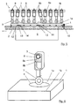
- the concrete blocks 1 leave the production plant in general in a production position, ie in an arrangement in which a plurality of concrete blocks 1 are arranged side by side in one layer. Such a production situation is exemplary in Fig. 1 shown.
- the concrete blocks 1 are applied in one layer in a regular arrangement on a substrate 2.
- the processing of the surfaces 1a and adjacent to the surfaces 1a edges 1b of the stones 1 by impactor 3, which are within a defined area 4 of the surface 1a of the stones 1 is substantially free to move.
- the impactors 3 are movably attached to a mounting device 5 or arranged or suspended.
- a vibration device 6 is provided to set the stones 1 and the impactors 3 to each other in such a way that the impactors 3 act on the surfaces 1 a and the exposed edges 1 b of the stones 1.
- the vibration device 6, which may for example consist of several unbalance generators, transmits the vibratory motion to the pad 2 and acts from there on the stones 1 and the impactor 3.
- the pad 2 can also represent the top of the vibration device 6, for example, a vibration table. However, the pad 2 may also represent a conveyor belt on which the stones 1 are placed. With regard to advantageous embodiments for this purpose and the initiation of the vibratory motion is on the DE 20 2004 020 206.9 directed.
- the impactors 3 are both - within the defined area 4 - to the surface 1 a freely movable and to each other.
- the impactors 3 can be made of any material.
- the impactors 3 are formed of hard metal, metal or steel.
- the shape of the impactor 3 can also be chosen arbitrarily, it has been found to be advantageous to form the impactor 3 spherical, annular, polygonal, cylindrical or disc-shaped.
- the impactors 3 are substantially spherical, but flattened on two opposite sides. This results in detail in particular from the FIGS. 4 . 6 and 7 ,
- the mounting device 5 extends plane-parallel to the surfaces 1a of the stones 1.
- the mounting device 5 in this case has a plurality of mounting elements 7, the each extend over the entire width of the stones 1 to be aged, ie transversely to the feed direction.
- the impactors 3 are arranged on fasteners 8 to the support members 7 and fixed or suspended.
- the fastening members 8 are shown as chains.
- the chains are designed as metal chains.
- the support elements 7 have, as can be seen in particular Fig. 4 results in rail-shaped receptacles 7a, in which the metal chains 8 are suspended.
- Each impactor 3 is individually connected via an individual fastening member 8 with the support member 7. If a shock body 3 has to be replaced, this is thus possible in a simple manner.
- the impactors 3 of a row 7 are close to each other, for example, a distance of 2 to 20 mm, preferably 5 to 10 mm.
- the support elements 7 or the entire support device 5 moves during the striking action of the impactor 3 on the stones 1.
- an irregular striking of the stones 1 is supported by the impactors 3.
- an oscillating movement of the support members 7 preferably such that the support members 7 are axially reciprocated. This can be achieved constructively by known means (e.g., an eccentric bearing or a random pneumatic cylinder).
- FIGS. 5, 6 and 7 is one to the FIGS. 2 to 4 alternative embodiment of the fastening members 8 shown.
- the fastening members 8 in this case have a profile through which an inner space 8a is formed, which is suitable, the (in Embodiment tubular or rod-shaped) support member 7 to be included so that the fastening member 8 is movable relative to the support member 7 such that arranged on the attachment member 8 or associated impactor 3 both a lifting movement and a movement within the defined area. 4 can perform.
- the fastening member 8 is formed as a correspondingly curved square profile.
- the defined area 4 has an elliptical shape.
- the impactors 3 30 to 200 mm, preferably 50 to 150 mm, can be deflected in the direction of passage. Furthermore, it can be provided that the next row 7 with impactors 3 has a distance from the previous row 7 with impactors 3, which is 10 to 20 mm greater than the maximum deflection of the striking body 3 during operation.
- the attachment members 8, including the impactors 3 in the embodiment has a length of 200 mm. It has proven generally advantageous to have a length of 100 to 400 mm. How out Fig. 5 can be seen, the support members 7 at regular intervals spacers 9, which ensure a defined arrangement of the fastening members 8 of a row and prevent tilting with other adjacently arranged fastening members 8.
- the interior 8a of the fastening members 8 may be divided by an intermediate bottom 8b, whereby in particular the lifting movement of the impactor 3 is limited accordingly.
- the intermediate bottom 8b is variably adjustable, whereby the lifting movement - optionally depending on the aging stones 1 - can be changed.
- Fig. 7 shows an arrangement of the impactor 3 such that the impactor 3 are aligned against the passage direction in the idle state.
- the striking bodies 3 or the fastening members 8 are aligned vertically (shown in dashed lines).
- the orientation of the impactor 3 in the idle state is chosen such that sets a vertical orientation during operation.
- the fastening members 8 are weighted at their forward in the direction of passage of the stones 1 side by an additional weight 15 (this can also be integrated into the fastening member).
- the additional weight 15 may also be attached to the impactor 3. Due to the additional weight 15 ensures that the impactor 3 is inclined in the opposite direction to the conveying direction. Such an inclination can also be achieved in other ways, for example by an unsymmetrical or disproportionate suspension and / or design of the fastening members 8 or the striking bodies 3.
- At least the rows 7 of impact bodies 3 arranged in the inlet region, i. the row of striking bodies 3, which pass the stones first when introduced into the aging area, are inclined in the direction of passage (not shown). This can be done structurally analogous to the inclination against the passage direction.
- the advantage is that a tilting of the stones 1 with the impactors 3 is avoided and the stones 1 can thus be easily supplied.
- the stones 1 are conveyed by means of a conveyor 10 below the impactors 3, i. go through the actual aging area.
- a plurality of different conveyors 10 are known.
- the conveyor is designed as a chain conveyor 10 with a push rod 11, which the stones 1 on the pad 2, i. in the actual aging area pushes directly over the vibrating table.
- the chain conveyor 10 passes through the stones 1 continuously below the impactors 3. The throughput speed can be determined in connection with the overall production rate or the aging result to be achieved.
- the chain conveyor 10 merely pushes in the intended position the stones 1 to be aged, for example an entire production position, and the stones 1 do not break during the aging process pushed forward (discontinuous promotion). After completion of the aging process, ie after the impactors 3 have completed their impact on the surfaces 1a and the adjacent edges 1b of the stones 1 to the desired extent, the chain conveyor 10 can carry the stones 1 on and bring a new position in the vacated space.
- the chain conveyor 10 is designed as a circulating conveyor.
- the two pull chains of the chain conveyor 10 are guided in the embodiment outside of the vibration device 6 and are thus not affected by vibrations in their functionality. In principle, a variety of design measures are conceivable to achieve that the chain conveyor 10 is not exposed to vibration.
- the push rod 11, which is arranged between the two circulating chains of the chain conveyor 10, has a distance to the vibration table or the base 2, which ensures that the vibration table or the base 2 does not come into contact with the push rod 11.
- the distance between the push rod and the top of the pad 2 and the vibrating table must therefore be greater than the maximum vibration of the vibrating table or pad 2 in the direction of the push rod 11.
- the vibrating table or Pad 2 vibrates or moves the vibrating table or Pad 2 not more than a maximum of 4 mm in the direction of the push rod 11, so that a distance of, for example, 10 mm sufficient to ensure that the vibration table or the pad 2, the push rod 11 is not touched and this can thus be quiet and unbeaten ,
- the distance between the push rod 11 and the top of the vibrating table or the base 2 depends on the oscillation width or the strength of the vibration.
- Fig. 1 shows a particularly advantageous embodiment of the push rod 11, which is particularly suitable for use in the device according to the invention.
- the push rod 11 is provided with a plurality of bearings 16 and rotatable elements, such as rollers.
- the bearings 16 cause that the stones 1, if they come into contact with the push rod 11 due to their vibrations, rub only minimally on the push rod 11, whereby only little kinetic energy is lost.
- the bearings 16 may be provided that the bearings 16 have a width of 5 to 30 mm, preferably 10 mm, and are arranged at a distance of 20 to 50 mm, preferably 30 mm.
- a push rod 11 can also be used independently of the solution according to the invention in other devices in which stones 1 are aged by means of a combination of a vibration device and impactors, which are arranged on the surface of the stones 1.
- Fig. 1 shows lateral boundaries 12 which are intended to prevent lateral escape of the stones 1 during the vibration process.
- boundaries 12 may also be provided in the direction of passage in front of and behind the bricks 1.
- the boundaries 12 can also serve as dust protection.
- the holding device 5 has a protective hood or the like, which comprises the to be aged layer of stones 1, so as to reduce an erosion of rock dust.
- the boundaries 12 are decoupled from the vibration device 6, so do not vibrate.
- the push rod 11 conveys in the direction of passage, without disturbing the lateral boundaries 12.
- the push rod 11 may be connected, for example, below or above the lateral boundaries 12 with the chain conveyor 10.
- the means 13 are formed as ramp-shaped elevations, which raise the stones when they pass with their bottom, the ramp-shaped elevations 13, according to.
- the elevations 13 may be provided with rollers 14 and bearings.
- ramps 13 can also be realized if the conveying device is designed as a belt conveyor, in which case the belt runs over the elevations 13 got to.
- An education as a chain conveyor 10 with a push rod 11 has been found to be advantageous for this purpose.
- the means 13 can in many kinds, for example as projections, as extendable stamp according to the US 2002/0145224 A1 or the like may be formed. It is also conceivable that the means 13 are formed by a wave-shaped configuration of the base 2 and the vibration table.
- the means 13 to raise the stones 1 at least in some areas so that the raised part of the stones 1 protrudes in the direction of the impactor 3 and a stronger impact of the impactor 3 is supplied can also regardless of the inventive concept of the movable attachment of the impactor. 3 be used.
- the processing of this sub-area can be intensified or reinforced.
- a desired aging result can be achieved in a simple manner.
- the solution according to the invention is also suitable for the aging of split or split stones, which generally have an uneven surface or surface provided with elevations and depressions.
- the gap surface of the stone 1 with its fracture surface is facing the impactors 3.
- FIGS. 8 to 12 three different advantageous conveyors 10 can be seen, which are not only for the inventive solution, but generally for conveying a plurality of stones, preferably stones, which are arranged in a production situation, are suitable.
- Fig. 8 and Fig. 9 show the conveyor 10 in a particularly inexpensive embodiment.
- the two chain strands of the chain conveyor each run in the edge region of the base 2 and are arranged such that they are not or not substantially vibrated by the vibration device 6.
- the push rod 11 already described is arranged, which serves to move the resting on the base 2 stones 1 in the conveying direction.
- the push rod 11 pushes the stones 1 on the base 2.
- a limiting rod 17 is shown, which is arranged in the conveying direction in front of the push rod 11.
- the limiting rod 17 which is arranged analogously to the push rod 11 between the chain strands of the chain conveyor 10 and connected to these, to prevent the stones 1 to the front, ie in the conveying direction, can escape.
- the limiting rod 17 could in principle also as.
- Push rod may be formed for a further layer of stones, but this has not proven to be advantageous. If a distance is left between the limiting bar 17 and a push rod 11 for a further layer of stones 1, the limiting bar 17 can be adjusted to different lengths of stone layers, without affecting all other push and limit bars.
- the change in length between a push rod 11 and an associated limiting rod 17 for receiving a stone layer thus affects only the distance between the limiting rod 17 and a leading further push rod 11. It is thus possible to select for each layer of stone a separate grid and possibly to change, without affecting the grid size of other units (push rod / limiting rod) has. It is therefore according to the in Fig. 8 and Fig. 9 illustrated embodiment, per stone position a push rod 11 and a limiting rod 17 to use.
- Both the push rod 11 and the limiting rod 17 may be formed in a preferred embodiment as a flat iron or the like.
- FIGS. 10 and 11 a preferred embodiment of the conveyor 10 is shown, which differs from the in the FIGS. 8 and 9 illustrated embodiment characterized in that mounted on the limiting rod 17, a support 18 and is attached.
- the limiting rod 17 thus serves as tie rods for the support 18.
- the stones are therefore in contrast to the in Fig. 8 and Fig. 9 illustrated embodiment no longer during the aging process on the pad 2, but on the support 18, which is essentially drawn from the limiting rod 17 and the chain conveyor 10 on the pad 2.
- the support 18 is in contact with the support 2 or the vibration device 6 in such a way that the support 18 is vibrated so that the stones 1 arranged on the support 18 also vibrate or hop.
- the support 18 is preferably formed of an elastic material. Particularly suitable for this purpose is a rubber mat 18.
- the rubber mat 18 may also be connected to the push rod 11.
- the rubber mat 18 moves at the same speed as the chain conveyor 10.
- the rubber mat 18 is disposed substantially between the limiting rod 17 and the push rod 11.
- the rubber mat 18 may also be longer or shorter than the distance between the limiting rod 17 and the push rod 11.
- the pad 18 and the rubber mat has been found to be particularly significant for a good aging result. This is due to the fact that in a conveyor 10, as this in Fig. 8 and Fig. 9 is shown, the thrust, the push rod 11 exerts on the stones 1, is getting larger the closer the stones 1 are arranged on the push rod 11. It may happen that the stones 1 are pushed together in such a way that the stones 1 in particular in the region of the push rod 11 less or no longer bounce. This effect is all the more visible, the smaller the stones are, because the rows of stones, on which a lower thrust pressure is exerted, so the rows of stones that are forward in the conveying direction, hop significantly higher or vibrate much stronger and thus struck their stone edges stronger become.
- the entire conveyor 10 can be slightly inclined, so that the stones 1 viewed in the conveying direction run slightly downward, whereby the effect that they migrate relative to the support 18 in the conveying direction to the rear, is counteracted.
- the edition 18 offers another advantage over the in Fig. 8 and Fig. 9 illustrated embodiment.
- the risk of breakage in very thin stones or long or large stones is relatively large.
- the support 18, in particular when it is formed of an elastic material the risk of breakage is reduced considerably, since the stones 1 no longer impinge on the base 2, which is usually formed of steel, but on an elastic material, preferably rubber.
- Fig. 12 is a variation of the in 10 and FIG. 11 illustrated embodiment of the conveyor 10, which has substantially the same advantages.
- the embodiment according to Fig. 12 also has a chain conveyor 10 and a push rod 11 and optionally a limiting rod 17, which analogous to the embodiments according to Fig. 8 and Fig. 9 respectively.
- 10 and FIG. 11 are arranged.
- the support 18 is designed as a circulating conveyor belt, which is preferably formed substantially of an elastic material, such as rubber.
- the conveyor belt 18 extends in such a way that it is vibrated by the vibration device 6, whereby the resting stones 1 hop or vibrate.
- the conveyor 10 is preferably arranged such that neither the chain strands nor the push rod 11 or the limiting rod 17 vibrate.
- the conveyor belt 18 is connected to one or more limiting rods 17 or push rods 11.
- the stones 1 due to their vibration (at low speed) move backwards relative to the conveyor belt 18. This rearward movement is limited by the push rod 11 accordingly.
- the thrust pressure which the push rod 11 exerts on the stones 1 is so small that it does not disturb the vibration or the hopping movement of the stones 1.
- the limiting rod 17 prevents the stones 1 can leave the intended area forward.
- a chain conveyor 10 may in the embodiments according to the FIGS. 8 to 12
- another conveyor which is preferably configured circumferentially, can be used.
- Fig. 13 shows an embodiment of the push rod 11 and the limiting rod 17, which is particularly suitable for the aging of trapezoidal in cross-section or generally unstable in their position stones 1.
- Such stones 1 may be, for example, split or split stones, which generally have an uneven or raised and recessed surface.
- the inventor has found that regardless of the embodiment of the conveyor (in Fig. 13 not shown) and regardless of how the stones are transported through the aging area ( FIGS. 8 to 12 ) the aging result of stones 1, which rest unstable on the pad 2 can be improved by the push rod 11 and the limiting rod 17 are formed such that they support the stones 1.
- both the push rod 11 and the limiting rod 17 an additional support member 11a and 17a.
- a plurality of support elements may be provided or the push rod 11 and the limiting rod 17 as such have a shape which is suitable to support the stones 1 and to avoid their tilting.
- the support elements 11a, 17a it is achieved that the surfaces 1a of the stones 1 form a horizontal plane as possible, so that the stone surfaces 1a can be advantageously aged by the impact body 3.
Landscapes
- Engineering & Computer Science (AREA)
- Mechanical Engineering (AREA)
- Structural Engineering (AREA)
- Chemical & Material Sciences (AREA)
- Ceramic Engineering (AREA)
- Mining & Mineral Resources (AREA)
- Processing Of Stones Or Stones Resemblance Materials (AREA)
- Revetment (AREA)
- Investigating Or Analyzing Materials By The Use Of Ultrasonic Waves (AREA)
- Preparation Of Clay, And Manufacture Of Mixtures Containing Clay Or Cement (AREA)
- Analysing Materials By The Use Of Radiation (AREA)
- Press-Shaping Or Shaping Using Conveyers (AREA)
- Curing Cements, Concrete, And Artificial Stone (AREA)
- Prostheses (AREA)
- Jigging Conveyors (AREA)
- Devices For Post-Treatments, Processing, Supply, Discharge, And Other Processes (AREA)
Priority Applications (2)
| Application Number | Priority Date | Filing Date | Title |
|---|---|---|---|
| SI200631173T SI1893391T1 (sl) | 2005-06-22 | 2006-05-09 | Postopek in naprava za umetno staranje kamenja |
| PL06742835T PL1893391T3 (pl) | 2005-06-22 | 2006-05-09 | Sposób i urządzenie do sztucznego postarzania cegieł |
Applications Claiming Priority (3)
| Application Number | Priority Date | Filing Date | Title |
|---|---|---|---|
| DE102005029212 | 2005-06-22 | ||
| DE102005056163.2A DE102005056163B4 (de) | 2005-06-22 | 2005-11-23 | Verfahren und Vorrichtung zum künstlichen Altern von Steinen |
| PCT/EP2006/004292 WO2006136235A2 (de) | 2005-06-22 | 2006-05-09 | Verfahren und vorrichtung zum künstlichen altern von steinen |
Publications (2)
| Publication Number | Publication Date |
|---|---|
| EP1893391A2 EP1893391A2 (de) | 2008-03-05 |
| EP1893391B1 true EP1893391B1 (de) | 2011-08-24 |
Family
ID=36847856
Family Applications (1)
| Application Number | Title | Priority Date | Filing Date |
|---|---|---|---|
| EP06742835A Active EP1893391B1 (de) | 2005-06-22 | 2006-05-09 | Verfahren und vorrichtung zum künstlichen altern von steinen |
Country Status (14)
| Country | Link |
|---|---|
| EP (1) | EP1893391B1 (pl) |
| KR (1) | KR101297796B1 (pl) |
| AT (1) | ATE521465T1 (pl) |
| AU (1) | AU2006261374B2 (pl) |
| BR (1) | BRPI0612627B1 (pl) |
| CA (1) | CA2612884C (pl) |
| DE (1) | DE102005056163B4 (pl) |
| DK (1) | DK1893391T3 (pl) |
| ES (1) | ES2372304T3 (pl) |
| MX (1) | MX2007016163A (pl) |
| PL (1) | PL1893391T3 (pl) |
| RU (1) | RU2393086C2 (pl) |
| SI (1) | SI1893391T1 (pl) |
| WO (1) | WO2006136235A2 (pl) |
Cited By (6)
| Publication number | Priority date | Publication date | Assignee | Title |
|---|---|---|---|---|
| DE102022127281A1 (de) | 2022-10-18 | 2024-04-18 | Baustoffwerke Gebhart & Söhne GmbH & Co. KG | Vorrichtung und Verfahren zum künstlichen Altern von Steinen |
| DE102022127331A1 (de) | 2022-10-18 | 2024-04-18 | Baustoffwerke Gebhart & Söhne GmbH & Co. KG | Verfahren und Vorrichtung zur Herstellung eines Verbundkörpers |
| DE102022127333A1 (de) | 2022-10-18 | 2024-04-18 | Baustoffwerke Gebhart & Söhne GmbH & Co. KG | Verfahren und Vorrichtung zur Herstellung eines Verbundkörpers |
| WO2024083944A1 (de) | 2022-10-19 | 2024-04-25 | Baustoffwerke Gebhart & Soehne Gmbh & Co. Kg | Verfahren und vorrichtung zur herstellung eines bedruckten betonkörpers, sowie bedruckter betonkörper |
| WO2024083943A1 (de) | 2022-10-19 | 2024-04-25 | Baustoffwerke Gebhart & Soehne Gmbh & Co. Kg | Verfahren und vorrichtung zur herstellung eines bedruckten betonkörpers, sowie bedruckter betonkörper |
| WO2025172357A1 (de) | 2024-02-13 | 2025-08-21 | Baustoffwerke Gebhart & Soehne Gmbh & Co. Kg | Pflasterstein, verfahren zum herstellen eines pflastersteins und produktionslage oder palettenlage von pflastersteinen |
Families Citing this family (3)
| Publication number | Priority date | Publication date | Assignee | Title |
|---|---|---|---|---|
| ITBO20080380A1 (it) * | 2008-06-16 | 2009-12-17 | Penta Automazioni Ind S R L | Macchina di invecchiamento artificiale di manufatti per costruzioni edili |
| DE102015108257B4 (de) | 2015-05-26 | 2022-08-04 | Metten Stein + Design Gmbh & Co. Kg | Vorrichtung zur Bearbeitung von Betonsteinen |
| CN110744691B (zh) * | 2019-09-30 | 2024-12-20 | 福建泉工股份有限公司 | 砌砖做旧设备 |
Family Cites Families (13)
| Publication number | Priority date | Publication date | Assignee | Title |
|---|---|---|---|---|
| SU79912A1 (ru) * | 1949-01-19 | 1949-11-30 | Ф.Т. Бущенко | Станок дл фактурной обработки гранитных блоков |
| US4263240A (en) * | 1978-01-27 | 1981-04-21 | Richtex Corporation | Apparatus and methods for forming simulated old brick |
| DK264478A (da) | 1978-06-13 | 1979-12-14 | Sf Sten Ag | Betonsten samt fremgangsmaade og apparat til fremstilling af brosten af beton |
| DE3621276A1 (de) | 1986-06-25 | 1988-01-07 | Aicheler & Braun Gmbh Betonwer | Verfahren und vorrichtung zum kuenstlichen altern von betonsteinen |
| BE1010944A3 (nl) | 1997-02-25 | 1999-03-02 | Ebema Naamloze Vennootschap | Werkwijze en inrichting voor het verouderen van stenen. |
| DE19845174A1 (de) * | 1998-10-01 | 2000-04-06 | Sf Koop Gmbh Beton Konzepte | Verfahren und Vorrichtung zur mechanischen Bearbeitung von Betonsteinen |
| US6279291B1 (en) * | 1999-09-22 | 2001-08-28 | Naamloze Venootschap Ebema | Method of ageing manufactured building components |
| DE10039463A1 (de) | 2000-08-12 | 2002-02-28 | Omag Ostfriesische Maschb Ag | Verfahren und Vorrichtung zur Herstellung von Betonsteinen mit unregelmäßigen Rändern |
| DE10061464C2 (de) | 2000-09-04 | 2002-07-11 | Ingo Averkamp | Maschine zum Kantenbrechen noch nicht ausgehärteter Betonsteine |
| CA2343338C (en) | 2001-04-09 | 2006-10-03 | Charles Ciccarello | Apparatus for roughing surfaces of concrete casted blocks |
| CA2349095C (en) | 2001-05-28 | 2006-11-28 | Techo-Bloc, Inc. | Apparatus and method for roughing surfaces of concrete casted blocks |
| CA2464267A1 (en) * | 2004-03-31 | 2005-09-30 | Unknown | Improvement in an apparatus for ageing artificial stone |
| DE202004020206U1 (de) | 2004-12-27 | 2005-03-03 | Baustoffwerke Gebhart & Söhne GmbH & Co. KG | Vorrichtung zum künstlichen Altern von Steinen |
-
2005
- 2005-11-23 DE DE102005056163.2A patent/DE102005056163B4/de not_active Expired - Lifetime
-
2006
- 2006-05-09 PL PL06742835T patent/PL1893391T3/pl unknown
- 2006-05-09 AU AU2006261374A patent/AU2006261374B2/en active Active
- 2006-05-09 EP EP06742835A patent/EP1893391B1/de active Active
- 2006-05-09 RU RU2008102231/03A patent/RU2393086C2/ru active
- 2006-05-09 KR KR1020087001642A patent/KR101297796B1/ko active Active
- 2006-05-09 ES ES06742835T patent/ES2372304T3/es active Active
- 2006-05-09 WO PCT/EP2006/004292 patent/WO2006136235A2/de not_active Ceased
- 2006-05-09 AT AT06742835T patent/ATE521465T1/de active
- 2006-05-09 MX MX2007016163A patent/MX2007016163A/es active IP Right Grant
- 2006-05-09 BR BRPI0612627-8A patent/BRPI0612627B1/pt active IP Right Grant
- 2006-05-09 DK DK06742835.9T patent/DK1893391T3/da active
- 2006-05-09 CA CA2612884A patent/CA2612884C/en active Active
- 2006-05-09 SI SI200631173T patent/SI1893391T1/sl unknown
Cited By (12)
| Publication number | Priority date | Publication date | Assignee | Title |
|---|---|---|---|---|
| DE102022127281A1 (de) | 2022-10-18 | 2024-04-18 | Baustoffwerke Gebhart & Söhne GmbH & Co. KG | Vorrichtung und Verfahren zum künstlichen Altern von Steinen |
| DE102022127331A1 (de) | 2022-10-18 | 2024-04-18 | Baustoffwerke Gebhart & Söhne GmbH & Co. KG | Verfahren und Vorrichtung zur Herstellung eines Verbundkörpers |
| DE102022127333A1 (de) | 2022-10-18 | 2024-04-18 | Baustoffwerke Gebhart & Söhne GmbH & Co. KG | Verfahren und Vorrichtung zur Herstellung eines Verbundkörpers |
| WO2024083765A1 (de) | 2022-10-18 | 2024-04-25 | Baustoffwerke Gebhart & Soehne Gmbh & Co. Kg | Verfahren und vorrichtung zur herstellung eines verbundkörpers |
| WO2024083767A1 (de) | 2022-10-18 | 2024-04-25 | Baustoffwerke Gebhart & Soehne Gmbh & Co. Kg | Verfahren und vorrichtung zur herstellung eines verbundkörpers |
| WO2024083766A1 (de) | 2022-10-18 | 2024-04-25 | Baustoffwerke Gebhart & Soehne Gmbh & Co. Kg | Vorrichtung und verfahren zum künstlichen altern von steinen |
| EP4605191A1 (de) * | 2022-10-18 | 2025-08-27 | Baustoffwerke Gebhart & Soehne GmbH & Co. KG | Vorrichtung und verfahren zum künstlichen altern von steinen |
| WO2024083944A1 (de) | 2022-10-19 | 2024-04-25 | Baustoffwerke Gebhart & Soehne Gmbh & Co. Kg | Verfahren und vorrichtung zur herstellung eines bedruckten betonkörpers, sowie bedruckter betonkörper |
| WO2024083943A1 (de) | 2022-10-19 | 2024-04-25 | Baustoffwerke Gebhart & Soehne Gmbh & Co. Kg | Verfahren und vorrichtung zur herstellung eines bedruckten betonkörpers, sowie bedruckter betonkörper |
| DE102022127582A1 (de) | 2022-10-19 | 2024-04-25 | Baustoffwerke Gebhart & Söhne GmbH & Co. KG | Verfahren und Vorrichtung zur Herstellung eines bedruckten Betonkörpers |
| DE102022127578A1 (de) | 2022-10-19 | 2024-04-25 | Baustoffwerke Gebhart & Söhne GmbH & Co. KG | Verfahren und Vorrichtung zur Herstellung eines bedruckten Betonkörpers |
| WO2025172357A1 (de) | 2024-02-13 | 2025-08-21 | Baustoffwerke Gebhart & Soehne Gmbh & Co. Kg | Pflasterstein, verfahren zum herstellen eines pflastersteins und produktionslage oder palettenlage von pflastersteinen |
Also Published As
| Publication number | Publication date |
|---|---|
| WO2006136235A2 (de) | 2006-12-28 |
| WO2006136235A3 (de) | 2007-04-19 |
| ES2372304T3 (es) | 2012-01-18 |
| DE102005056163B4 (de) | 2023-04-13 |
| KR101297796B1 (ko) | 2013-08-19 |
| RU2393086C2 (ru) | 2010-06-27 |
| CA2612884A1 (en) | 2006-12-28 |
| PL1893391T3 (pl) | 2012-03-30 |
| EP1893391A2 (de) | 2008-03-05 |
| BRPI0612627B1 (pt) | 2017-06-27 |
| DE102005056163A1 (de) | 2006-12-28 |
| CA2612884C (en) | 2011-01-04 |
| KR20080022582A (ko) | 2008-03-11 |
| BRPI0612627A2 (pt) | 2010-11-23 |
| MX2007016163A (es) | 2008-03-10 |
| DK1893391T3 (da) | 2011-12-05 |
| AU2006261374A1 (en) | 2006-12-28 |
| SI1893391T1 (sl) | 2012-01-31 |
| ATE521465T1 (de) | 2011-09-15 |
| AU2006261374B2 (en) | 2011-04-21 |
| RU2008102231A (ru) | 2009-07-27 |
Similar Documents
| Publication | Publication Date | Title |
|---|---|---|
| EP1893391B1 (de) | Verfahren und vorrichtung zum künstlichen altern von steinen | |
| EP0339308B1 (de) | Verfahren und Vorrichtung zum künstlichen Altern von Betonsteinen sowie künstlich gealterter Betonstein | |
| EP1699609B1 (de) | Verfahren und vorrichtung zum künstlichen altern von steinen | |
| DE2301653A1 (de) | Verfahren zur verbesserung der griffigkeit eines strassenbelags und strassenbelagbehandlungsgeraet zur durchfuehrung dieses verfahrens | |
| WO2024083766A1 (de) | Vorrichtung und verfahren zum künstlichen altern von steinen | |
| EP0031787A1 (de) | Verfahren und Einrichtung zum Wiederaufbereiten von drahtmattenbewehrten Gasbetonformstücken | |
| WO1997024210A1 (de) | Vorrichtung zur bearbeitung von oberflächen | |
| DE102009007972B4 (de) | Bearbeitungsmaschine zum Bearbeiten von Steinen | |
| DE202006005773U1 (de) | Vorrichtung zum künstlichen Altern von Steinen | |
| DE3700676C2 (pl) | ||
| EP0278231A1 (de) | Steinbearbeitungsvorrichtung | |
| DE10349529A1 (de) | Verfahren und Vorrichtung zum künstlichen Altern von Steinen | |
| DE10307447A1 (de) | Verfahren und Vorrichtung zum künstlichen Altern einer Formation von Steinen | |
| EP2747968B1 (de) | Vorrichtung und verfahren zum künstlichen altern von steinen | |
| EP3057750B1 (de) | Verfahren zum künstlichen altern von steinen | |
| DE202004020206U1 (de) | Vorrichtung zum künstlichen Altern von Steinen | |
| DE3631646A1 (de) | Vorrichtung zum bearbeiten von natursteinoberflaechen, sowie ein verfahren und eine natursteinplatte | |
| EP4257318A1 (de) | Vorrichtung und verfahren zur bearbeitung von formsteinen | |
| DE202005019683U1 (de) | Vorrichtung zum künstlichen Altern von Steinen | |
| DE102004058256B4 (de) | Vorrichtung zur Bearbeitung von in einer Steinlage angeordneten Steinen | |
| DE690875C (de) | Verfahren und Vorrichtung zum Zerkleinern von besonders hartem Gestein | |
| DE10234932B4 (de) | Verfahren und Vorrichtung zum Herstellen eines Betonprodukts mit einem Oberflächenbereich mit freigelegtem Korn | |
| DE10333213A1 (de) | Vorrichtung und Verfahren zum künstlichen Altern von Steinen | |
| DE102005029213A1 (de) | Vorrichtung zum künstlichen Altern von Steinen | |
| DE10039463A1 (de) | Verfahren und Vorrichtung zur Herstellung von Betonsteinen mit unregelmäßigen Rändern |
Legal Events
| Date | Code | Title | Description |
|---|---|---|---|
| PUAI | Public reference made under article 153(3) epc to a published international application that has entered the european phase |
Free format text: ORIGINAL CODE: 0009012 |
|
| 17P | Request for examination filed |
Effective date: 20080103 |
|
| AK | Designated contracting states |
Kind code of ref document: A2 Designated state(s): AT BE BG CH CY CZ DE DK EE ES FI FR GB GR HU IE IS IT LI LT LU LV MC NL PL PT RO SE SI SK TR |
|
| RIN1 | Information on inventor provided before grant (corrected) |
Inventor name: STAEHLE, MANFRED Inventor name: GEBHART, HANS Inventor name: WERNER, ROLAND |
|
| DAX | Request for extension of the european patent (deleted) | ||
| GRAP | Despatch of communication of intention to grant a patent |
Free format text: ORIGINAL CODE: EPIDOSNIGR1 |
|
| GRAS | Grant fee paid |
Free format text: ORIGINAL CODE: EPIDOSNIGR3 |
|
| GRAA | (expected) grant |
Free format text: ORIGINAL CODE: 0009210 |
|
| AK | Designated contracting states |
Kind code of ref document: B1 Designated state(s): AT BE BG CH CY CZ DE DK EE ES FI FR GB GR HU IE IS IT LI LT LU LV MC NL PL PT RO SE SI SK TR |
|
| REG | Reference to a national code |
Ref country code: GB Ref legal event code: FG4D Free format text: NOT ENGLISH |
|
| REG | Reference to a national code |
Ref country code: CH Ref legal event code: EP |
|
| REG | Reference to a national code |
Ref country code: IE Ref legal event code: FG4D Free format text: LANGUAGE OF EP DOCUMENT: GERMAN |
|
| REG | Reference to a national code |
Ref country code: DE Ref legal event code: R096 Ref document number: 502006010073 Country of ref document: DE Effective date: 20111027 |
|
| REG | Reference to a national code |
Ref country code: RO Ref legal event code: EPE |
|
| REG | Reference to a national code |
Ref country code: DK Ref legal event code: T3 |
|
| REG | Reference to a national code |
Ref country code: NL Ref legal event code: T3 |
|
| REG | Reference to a national code |
Ref country code: SE Ref legal event code: TRGR |
|
| REG | Reference to a national code |
Ref country code: CH Ref legal event code: NV Representative=s name: CABINET ROLAND NITHARDT CONSEILS EN PROPRIETE INDU |
|
| REG | Reference to a national code |
Ref country code: ES Ref legal event code: FG2A Ref document number: 2372304 Country of ref document: ES Kind code of ref document: T3 Effective date: 20120118 |
|
| PG25 | Lapsed in a contracting state [announced via postgrant information from national office to epo] |
Ref country code: IS Free format text: LAPSE BECAUSE OF FAILURE TO SUBMIT A TRANSLATION OF THE DESCRIPTION OR TO PAY THE FEE WITHIN THE PRESCRIBED TIME-LIMIT Effective date: 20111224 Ref country code: PT Free format text: LAPSE BECAUSE OF FAILURE TO SUBMIT A TRANSLATION OF THE DESCRIPTION OR TO PAY THE FEE WITHIN THE PRESCRIBED TIME-LIMIT Effective date: 20111226 |
|
| PG25 | Lapsed in a contracting state [announced via postgrant information from national office to epo] |
Ref country code: GR Free format text: LAPSE BECAUSE OF FAILURE TO SUBMIT A TRANSLATION OF THE DESCRIPTION OR TO PAY THE FEE WITHIN THE PRESCRIBED TIME-LIMIT Effective date: 20111125 Ref country code: CY Free format text: LAPSE BECAUSE OF FAILURE TO SUBMIT A TRANSLATION OF THE DESCRIPTION OR TO PAY THE FEE WITHIN THE PRESCRIBED TIME-LIMIT Effective date: 20110824 |
|
| REG | Reference to a national code |
Ref country code: PL Ref legal event code: T3 |
|
| REG | Reference to a national code |
Ref country code: SK Ref legal event code: T3 Ref document number: E 10821 Country of ref document: SK |
|
| PG25 | Lapsed in a contracting state [announced via postgrant information from national office to epo] |
Ref country code: EE Free format text: LAPSE BECAUSE OF FAILURE TO SUBMIT A TRANSLATION OF THE DESCRIPTION OR TO PAY THE FEE WITHIN THE PRESCRIBED TIME-LIMIT Effective date: 20110824 |
|
| REG | Reference to a national code |
Ref country code: HU Ref legal event code: AG4A Ref document number: E012969 Country of ref document: HU |
|
| PLBE | No opposition filed within time limit |
Free format text: ORIGINAL CODE: 0009261 |
|
| STAA | Information on the status of an ep patent application or granted ep patent |
Free format text: STATUS: NO OPPOSITION FILED WITHIN TIME LIMIT |
|
| 26N | No opposition filed |
Effective date: 20120525 |
|
| REG | Reference to a national code |
Ref country code: DE Ref legal event code: R097 Ref document number: 502006010073 Country of ref document: DE Effective date: 20120525 |
|
| PG25 | Lapsed in a contracting state [announced via postgrant information from national office to epo] |
Ref country code: MC Free format text: LAPSE BECAUSE OF NON-PAYMENT OF DUE FEES Effective date: 20120531 |
|
| PG25 | Lapsed in a contracting state [announced via postgrant information from national office to epo] |
Ref country code: BG Free format text: LAPSE BECAUSE OF FAILURE TO SUBMIT A TRANSLATION OF THE DESCRIPTION OR TO PAY THE FEE WITHIN THE PRESCRIBED TIME-LIMIT Effective date: 20111124 |
|
| PG25 | Lapsed in a contracting state [announced via postgrant information from national office to epo] |
Ref country code: LU Free format text: LAPSE BECAUSE OF NON-PAYMENT OF DUE FEES Effective date: 20120509 |
|
| REG | Reference to a national code |
Ref country code: FR Ref legal event code: PLFP Year of fee payment: 11 |
|
| REG | Reference to a national code |
Ref country code: FR Ref legal event code: PLFP Year of fee payment: 12 |
|
| REG | Reference to a national code |
Ref country code: FR Ref legal event code: PLFP Year of fee payment: 13 |
|
| REG | Reference to a national code |
Ref country code: CH Ref legal event code: NV Representative=s name: ACTOSPHERE SARL, CH |
|
| REG | Reference to a national code |
Ref country code: FR Ref legal event code: PLFP Year of fee payment: 18 |
|
| P01 | Opt-out of the competence of the unified patent court (upc) registered |
Effective date: 20230514 |
|
| PGFP | Annual fee paid to national office [announced via postgrant information from national office to epo] |
Ref country code: IE Payment date: 20240517 Year of fee payment: 19 |
|
| PGFP | Annual fee paid to national office [announced via postgrant information from national office to epo] |
Ref country code: DK Payment date: 20240522 Year of fee payment: 19 |
|
| PGFP | Annual fee paid to national office [announced via postgrant information from national office to epo] |
Ref country code: ES Payment date: 20240614 Year of fee payment: 19 |
|
| PGFP | Annual fee paid to national office [announced via postgrant information from national office to epo] |
Ref country code: SK Payment date: 20240506 Year of fee payment: 19 |
|
| PGFP | Annual fee paid to national office [announced via postgrant information from national office to epo] |
Ref country code: RO Payment date: 20240430 Year of fee payment: 19 Ref country code: FI Payment date: 20240521 Year of fee payment: 19 Ref country code: SI Payment date: 20240426 Year of fee payment: 19 |
|
| PGFP | Annual fee paid to national office [announced via postgrant information from national office to epo] |
Ref country code: PL Payment date: 20240426 Year of fee payment: 19 |
|
| PGFP | Annual fee paid to national office [announced via postgrant information from national office to epo] |
Ref country code: TR Payment date: 20240429 Year of fee payment: 19 Ref country code: SE Payment date: 20240522 Year of fee payment: 19 Ref country code: HU Payment date: 20240509 Year of fee payment: 19 |
|
| PGFP | Annual fee paid to national office [announced via postgrant information from national office to epo] |
Ref country code: FR Payment date: 20250326 Year of fee payment: 20 |
|
| PGFP | Annual fee paid to national office [announced via postgrant information from national office to epo] |
Ref country code: NL Payment date: 20250522 Year of fee payment: 20 |
|
| PGFP | Annual fee paid to national office [announced via postgrant information from national office to epo] |
Ref country code: DE Payment date: 20250521 Year of fee payment: 20 |
|
| PGFP | Annual fee paid to national office [announced via postgrant information from national office to epo] |
Ref country code: GB Payment date: 20250401 Year of fee payment: 20 |
|
| PGFP | Annual fee paid to national office [announced via postgrant information from national office to epo] |
Ref country code: LT Payment date: 20250424 Year of fee payment: 20 |
|
| PGFP | Annual fee paid to national office [announced via postgrant information from national office to epo] |
Ref country code: BE Payment date: 20250520 Year of fee payment: 20 Ref country code: IT Payment date: 20250331 Year of fee payment: 20 |
|
| PGFP | Annual fee paid to national office [announced via postgrant information from national office to epo] |
Ref country code: LV Payment date: 20250522 Year of fee payment: 20 |
|
| PGFP | Annual fee paid to national office [announced via postgrant information from national office to epo] |
Ref country code: AT Payment date: 20250519 Year of fee payment: 20 |
|
| PGFP | Annual fee paid to national office [announced via postgrant information from national office to epo] |
Ref country code: CZ Payment date: 20250428 Year of fee payment: 20 |
|
| PGFP | Annual fee paid to national office [announced via postgrant information from national office to epo] |
Ref country code: CH Payment date: 20250707 Year of fee payment: 20 |
|
| REG | Reference to a national code |
Ref country code: DK Ref legal event code: EBP Effective date: 20250531 |
|
| REG | Reference to a national code |
Ref country code: SK Ref legal event code: MM4A Ref document number: E 10821 Country of ref document: SK Effective date: 20250509 |
|
| PG25 | Lapsed in a contracting state [announced via postgrant information from national office to epo] |
Ref country code: FI Free format text: LAPSE BECAUSE OF NON-PAYMENT OF DUE FEES Effective date: 20250509 |
|
| PG25 | Lapsed in a contracting state [announced via postgrant information from national office to epo] |
Ref country code: HU Free format text: LAPSE BECAUSE OF NON-PAYMENT OF DUE FEES Effective date: 20250510 |
|
| PG25 | Lapsed in a contracting state [announced via postgrant information from national office to epo] |
Ref country code: SE Free format text: LAPSE BECAUSE OF NON-PAYMENT OF DUE FEES Effective date: 20250510 |
|
| PG25 | Lapsed in a contracting state [announced via postgrant information from national office to epo] |
Ref country code: SK Free format text: LAPSE BECAUSE OF NON-PAYMENT OF DUE FEES Effective date: 20250509 Ref country code: RO Free format text: LAPSE BECAUSE OF NON-PAYMENT OF DUE FEES Effective date: 20250509 |
|
| REG | Reference to a national code |
Ref country code: SE Ref legal event code: EUG |
|
| PG25 | Lapsed in a contracting state [announced via postgrant information from national office to epo] |
Ref country code: DK Free format text: LAPSE BECAUSE OF NON-PAYMENT OF DUE FEES Effective date: 20250531 Ref country code: IE Free format text: LAPSE BECAUSE OF NON-PAYMENT OF DUE FEES Effective date: 20250509 |