EP1890971B1 - Sammelverfahren und vorrichtung für vom löslichen anteil getrenntes pulver - Google Patents
Sammelverfahren und vorrichtung für vom löslichen anteil getrenntes pulver Download PDFInfo
- Publication number
- EP1890971B1 EP1890971B1 EP06798584.6A EP06798584A EP1890971B1 EP 1890971 B1 EP1890971 B1 EP 1890971B1 EP 06798584 A EP06798584 A EP 06798584A EP 1890971 B1 EP1890971 B1 EP 1890971B1
- Authority
- EP
- European Patent Office
- Prior art keywords
- powder
- soluble component
- solvent
- wash tank
- pipe line
- Prior art date
- Legal status (The legal status is an assumption and is not a legal conclusion. Google has not performed a legal analysis and makes no representation as to the accuracy of the status listed.)
- Ceased
Links
Images



Classifications
-
- B—PERFORMING OPERATIONS; TRANSPORTING
- B01—PHYSICAL OR CHEMICAL PROCESSES OR APPARATUS IN GENERAL
- B01D—SEPARATION
- B01D11/00—Solvent extraction
- B01D11/04—Solvent extraction of solutions which are liquid
-
- B—PERFORMING OPERATIONS; TRANSPORTING
- B01—PHYSICAL OR CHEMICAL PROCESSES OR APPARATUS IN GENERAL
- B01D—SEPARATION
- B01D29/00—Filters with filtering elements stationary during filtration, e.g. pressure or suction filters, not covered by groups B01D24/00 - B01D27/00; Filtering elements therefor
- B01D29/62—Regenerating the filter material in the filter
- B01D29/66—Regenerating the filter material in the filter by flushing, e.g. counter-current air-bumps
Definitions
- the present invention relates to an apparatus for collecting soluble component-removed powder that easily collects soluble component-removed powder by removing a solution in a tank, where soluble component- and poorly soluble component-containing powder and a solvent dissolving the soluble component are mixed, using suction force by vacuum pumping and prevents overload by adding backwashing in the suction of the solution, and a method of the same.
- a sedimentation method that precipitates soluble component-containing powder mixed with a solvent in a tank, thereafter repeats separating of the precipitated powder from the solvent containing the dissolved soluble component and a centrifugal method that separates particles by rotating a container filled with a solution where soluble component-containing powder and a solvent are mixed, using a difference in density of the solution and powder.
- a known sedimentation method is rapidly processed when the particles of soluble component-containing powder is 10 ⁇ m or more in size, whereas when the particles are smaller than that and have floatability, it takes a long time to precipitate the powder, which results in extending the process cycle to separate the powder from the solution and deteriorating workability.
- the aforementioned method has a problem in that even though the washing/desalting is effectively processed by loading of a filter, solids of which particle size is about 1 ⁇ m due to the limitation of unwoven fabric may come out and not only a large amount of space and cost for mounting the belt filter are required, but a specific process is required to separate the inorganic solids from the surface of the filter.
- an object of the invention is to provide an apparatus that collects soluble component-removed powder by separating soluble component-removed powder from a mixture containing soluble component- and poorly soluble component-containing powder and a solvent dissolving the soluble component, regardless of the size and amount of particles and a method thereof.
- the above apparatus may include a bubble generator that is disposed at a lower portion of the filter in the wash tank, generates bubbles and guides the bubbles to the filter, a stirrer that is disposed in the wash tank and mixes the soluble component- and poorly soluble component-containing powder and the solvent, and a solvent supply valve that is disposed on the solvent supplier and controls the flow rate of the solvent supplied into the wash tank.
- a bubble generator that is disposed at a lower portion of the filter in the wash tank, generates bubbles and guides the bubbles to the filter
- a stirrer that is disposed in the wash tank and mixes the soluble component- and poorly soluble component-containing powder and the solvent
- a solvent supply valve that is disposed on the solvent supplier and controls the flow rate of the solvent supplied into the wash tank.
- the backwashing means may include a first opening/closing valve that is provided to the pipe line between the filter and the pump and controls the flow of the solvent flowing from the filter to the pump by opening and closing according to control of the controller; and a second opening/closing valve that is provided between the first opening/closing valve and the filter and controls the flow of the solvent supplied to the filter through the pipe line by opening and closing according to control of the controller.
- the controller may include a control part that outputs a control signal to change the operation of the pump and backwashing means on the basis of preset data value depending on component and content of the soluble component- and poorly soluble component-containing powder and the solvent that are put into the wash tank.
- the controller includes a pressure sensor that senses the vacuum pressure in the pipe line; and a control part that turns on the backwashing means when the pressure in the pipe line sensed by the pressure sensor is lower than a preset pressure.
- the pressure set by the control part is -0.8 kg/cm 2 .
- the apparatus includes a powder discharge time detecting means that detects the discharge time of the soluble component-removed powder discharged through the powder discharge port; and a discharge valve that is provided on the powder discharge port, in which the controller opens or closes the powder discharge port by controlling the discharge valve on the basis of data detected by the powder discharge time detecting means.
- the powder discharge time detecting means may be any one of a pH measuring part that measures pH of the solution in the wash tank containing the soluble component, and an electric conductivity measuring instrument that measures the electric conductivity of the solution in the wash tank containing the soluble component.
- the controller may open the discharge valve so that the soluble component-removed powder is discharged through the powder discharge port when the pH of the solution in the wash tank that is measured by the pH measuring part is a preset standard pH.
- the standard pH is determined depending on the type of powder put into the wash tank.
- the control part opens the discharge valve to discharge the soluble component-removed powder through the powder discharge port.
- the control part opens the discharge valve to discharge the soluble component-removed powder through the powder discharge port.
- the above standard pHs are just examples and the standard pH used as a basis of determination of discharge time of powder depends on the type of powder put in, therefore is not limited the above exemplary values.
- the controller opens the discharge valve so that the soluble component-removed powder is discharged through the powder discharge port when the electric conductivity measured by the electric conductivity measuring instrument is a preset standard electric conductivity.
- the standard electric conductivity is also determined depending on the type of powder put in the wash tank.
- the control part opens the discharge valve to discharge the soluble component-removed powder through the powder discharge port.
- the control part opens the discharge valve to discharge the soluble component-removed powder through the powder discharge port.
- the apparatus may include a powder-collecting tank that is disposed under the powder discharge port and collects the soluble component-removed powder discharged through the powder discharge port.
- a method is provided as called for in claim 11. outside through a pipe line, while vacuum pumping and filtering the solvent using a pump and a filter; (c) backwashing by inversely injecting a solvent to the filter through the pipe line to remove the soluble component-removed powder from the filter when the soluble component-removed powder is stuck on the surface of the filter; and (d) collecting the soluble component-removed powder by discharging the soluble component-removed powder out of the wash tank. Steps (a) to (d) are controlled by a control part.
- the method may further include stirring the soluble component- and poorly soluble component-containing powder and the solvent in the wash tank using a stirrer mounted in the wash tank, after the step (a).
- the present invention relates to an apparatus for collecting soluble component-removed powder that collects poorly soluble component-containing powder to recycle by removing the soluble component from the soluble component- and poorly soluble component-containing powder by filtering using a vacuum pump after mixing soluble component- and poorly soluble component-containing powder and a solvent, and a method of the same.
- it can be easily achieved to collect and utilize powder, after the soluble component is dissolved in a solvent, by vacuum pumping the solvent through a filter and then discharging a solution containing only the soluble component, further effectively prevent overload by removing the powder stuck on the surface of the filter by backwashing.
- a method of removing a soluble component from soluble component- and poorly soluble component-containing powder and collecting poorly soluble component-containing powder includes putting and mixing soluble component- and poorly soluble component-containing powder with a solvent in a wash tank (Step S1), pumping the mixed liquid outside the wash tank, in which as the soluble component of the powder is dissolved in the solvent, the liquid containing the soluble component is discharged outside through a filter and soluble component-removed and poorly soluble component-containing powder is not allowed to pass through the filter (Step S2), backwashing the filter by injecting a solvent from a pipe line to the filter to remove soluble component-removed and poorly soluble component-containing powder that is stuck on the surface of the filter while the liquid containing soluble component is discharged outside (Step S3), examining the discharge time of the soluble component-removed and poorly soluble component-containing powder (Step S4), discharging the poorly
- a detailed example of a collecting method including Steps S1 to S5 may be composed of 1putting soluble component- and poorly soluble component-containing powder and a solvent into a wash tank ⁇ 2mixing the powder with the solvent ⁇ 3discharging a solution containing soluble component outside the wash tank through a filter ⁇ 4backwashing when a load is generated by the poorly soluble component-containing powder stuck on the surface of the filter in discharging of the solution containing the soluble component outside the wash tank ⁇ 5repeating the steps of 3 and 4 ⁇ 6examining a reference line (top dead center and bottom dead center) shown on the wash tank to determine when the solvent is put into the wash tank ⁇ 7examining powder discharge time, when the amount of the solvent in the wash tank is reduced to the bottom dead center by the repetition of the steps of 3 and 4 ⁇ 8additionally supplying a solvent in the wash tank until it reaches the top dead center, when it is not the powder discharge time ⁇ 9re-processing from 2 to 7 ⁇ 10discharging poorly soluble component-
- Step S1 it is preferable to add stirring of the solvent using a stirrer rotated in the wash tank by a motor to easily dissolve an impurity, that is, the soluble component (for example, salt component) contained in the powder.
- the soluble component for example, salt component
- Step S2 it is preferable to form the filter at an end of the pipe line and mount a porous polymer filter, a ceramic filter, or a mesh-shaped metallic filter depending on the size of particles of powder to prevent the powder from passing, but the material is not limited thereto.
- the filling, discharging, and backwashing of the solvent may be controlled according to pressure through checking vacuum negative pressure in the pipe line or at individual time by periodically repeating the vacuum pumping time and backwashing time.
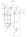
- an apparatus removing a soluble component from soluble component- and poorly soluble component-containing powder and collecting the poorly soluble component includes: a wash tank 100 that has an internal receiving space; a powder supplier 120 that is disposed above the wash tank 100 and supplies soluble component- and poorly soluble component-containing ) powder to the wash tank 100; a solvent supplier 110 that is disposed above the wash tank 100 and supplies a solvent dissolving the soluble component contained in the powder to the wash tank 100; a pipe line 250 of which an end is received in the wash tank 100 and the other end is placed outside the wash tank 100; a filter 270 that is provided at the end of the pipe line 250 in the wash tank 100; a pump 200 that is connected with the outside end of the pipe line 250 and applies vacuum negative pressure in the pipe line 250 at ON; a backwashing means that injects a solvent to the filter 270 through the pipe line 250 to remove, from the filter 270, the soluble component-removed powder stuck to the filter 270
- the solvent supplier 110 and the powder supplier 120 which are shaped as a pipe, are provided above the wash tank 100 to supply a solvent and powder, reference lines that indicate a top dead center and a bottom dead center are provided at the upper and lower portion of the wash thank to determine addition of a solvent, and the powder discharge port 130 is provided at the bottom to discharge the soluble component-removed and poorly soluble component-containing powder.
- the discharging of the powder discharge port 130 may be automatically controlled by the controller or manually controlled by opening or closing a valve to discharge. As shown in FIG. 4 by way of example, the controller may control discharge/stop of discharge of the powder by turning on/off a discharge valve 131 according to data detected by a powder discharge time detecting means 600.
- the powder discharge time detecting means 600 may be a pH measuring part that measures pH of the solution in the wash tank 100 that contains a soluble component as the soluble component of the powder is dissolved in the solvent, or an electric conductivity measuring instrument that measures the conductivity of the solution in the wash tank 100 that contains a soluble component as the soluble component of the powder is dissolved in the solvent.
- the powder discharge time detecting means 600 is the pH measuring part, it is preferable to control the powder discharge port 130 such that the powder is discharged when the pH of the solution in the wash tank 100 that is measured by the pH measuring part is a preset standard pH value.
- the powder discharge time detecting means 600 is the electric conductivity measuring instrument
- a stirrer 150 which is rotated by outside power, may be provided, or not, in the wash tank 100 to mix the powder with the solvent, and is composed of a motor 152 that is disposed outside the wash tank 100, a motor shaft 154 that is connected to the motor 152 and capable of rotating in the wash tank 100, and a propeller-shaped stirring fan 155 that is rotatably connected at the end of the motor shaft 154.
- a vane pump 200 may be used by way of an example of the pump 200 that generates vacuum negative pressure for discharging the solution in the wash tank 100 through the pipe line 250 by draining the fluid in the pipe line 250 outside.
- the vacuum negative pressure of the pump 200 ranges in -0.01 to -1.5 kg/cm 2 , but a possible pumping range is -0.1 to -0.99 kg/cm 2 in practice; however, if it is over or less than the range, vacuum negative pressure may not act or deteriorate the durability of components due to overpressure.
- the filter 270 is fixed to the end of the pipe line 250 at a lower portion in the wash tank 100 and may be a polymer filter having air holes suitable to the particle size of the powder, a mesh-shaped metallic filter, or a porous ceramic filter. As for a mesh-shaped filter, it is preferable to size the air hole such that the powder can not pass and the solution in which a salt or soluble component is dissolved can pass the filter.
- the backwashing means is composed of a first opening/closing valve 310 that is provided to the pipe line 250 between the filter 270 and the pump 200 and a second opening/closing valve 320 that is provided between the first opening/closing valve 310 and the filter 270 to supply water to the filter 270 from outside.
- the pressure of a solvent supplied from outside ranges about 0.01 to 4.0 kg/cm 2 , and the pressure should make the internal pressure of the pipe line 250, where the vacuum negative pressure is applied, positive, not negative, because excessive overpressure may cause deterioration of durability of components including the filter 270.
- the first and second opening/closing valve 310 and 320 are turned on/off according to control signals and open/close respective flow passage, and the first opening/closing valve 310 opens its flow passage to discharge the solution in the wash tank 100 outside through the pipe line 250 in pumping of the pump 200, and closes the flow passage in backwashing.
- the second opening/closing valve 320 is disposed on a backwashing-solvent supply pipe line 340 connecting the solvent supplier 110 and the pipe line 250, and is normally turned off, but is turned on while backwashing to supply the solvent in the solvent supplier 110 from the pipe line 250 to the filter 270 through the backwashing-solvent supply pipe line 340.
- a third opening/closing valve 330 which is a solvent supply valve that is capable of controlling the flow of the solvent to the wash tank 100 or the backwashing-solvent supply pipe line 340, is provided for the solvent supplier 110.
- the controller includes a pressure sensor 410 that is disposed in the pipe line 250 and senses the vacuum negative pressure in the pipe line 250 and a control part 400 that compares a pressure sensing signal of the pressure sensor 410 with a preset pressure and outputs a control signal controlling the on/off of the first and second opening/closing valve 310 and 320 for backwashing, when the compared signal becomes less than the preset pressure (when the vacuum negative pressure becomes larger than the preset pressure).
- control part 400 determines the starting time of backwashing on the basis of the internal pressure of the pipe line 250 is that the vacuum negative pressure in the pipe line 250 is variable depending on the amount of powder stuck on the surface of the filter 270, thus can be a standard of judgment for overpressure.
- the vacuum negative pressure set by the control part 400 is -0.8 kg/cm 2 , which is, as described above, for preventing overpressure of the vacuum negative pressure.
- the backwashing is preferably processed for the preset time determined by the control part 400 and also variable depending on the supply pressure of the solvent.
- the controller may select another control mode using a timer 420 such that the backwashing is periodically operated, on the basis of the size, content, component of the powder put into the wash tank 100 and the vacuum pumping time of the pump 200, not the vacuum pressure in the pipe line 250.
- the vacuum pumping and the backwashing can be periodically repeated by inputting the sort and the property etc. of the powder as data in advance and making the control part 400 find a vacuum pumping time of the pump 200 that corresponds to each data and input them into the timer 420.
- the pumping time of the pump 200 corresponding to the data inputted in advance to the control part 400 can be calculated and the backwashing can be periodically operated by inputting the calculated time to the timer 420.
- the timing of backwashing may be determined on the basis of the amount of fluid that is discharged to the pipe line through the filter using a flowmeter instead of the pressure sensor that senses the strength of the vacuum negative pressure.
- the third opening/closing valve 330 is turned on, a solvent is put into the wash tank 100 from the solvent supplier 110, and soluble component- and poorly soluble component-containing powder is put into the wash tank 100 from the powder supplier 120 and the they are mixed in the wash tank 100.
- the soluble component contained in the powder is dissolved in the solvent and separated from the powder, and then the soluble component-containing solution resulting from the dissolution of the soluble component in the solvent is flowed into the pipe line 250 through the filter 270 by vacuum pumping of the pump 200.
- a filtering is applied, in which poorly soluble component (that is, solid in the solution)-containing powder is left in the wash tank 100 by the filter 270 disposed at the end of the pipe line 250, and the soluble component-containing solution resulting from the dissolution of the soluble component in the solvent passes through the filter 270 and is discharged through the pipe line 250.
- poorly soluble component that is, solid in the solution
- the control part 400 turns on the first opening/closing valve 310 to open its flow passage and turns off the second opening/closing valve 320 to close its flow passage.
- backwashing is processed by a control mode on the basis of the above-mentioned vacuum negative pressure, operation timing, or discharge amount measured by a flowmeter.
- the second opening/closing valve 320 is turned on, the solvent in the solvent supplier 110 flows into the pipe line 250 through the backwashing solvent supply pipe line 340, and then flows in the wash tank 100 through the filter 270.
- control part 400 allows the previous vacuum pumping by turning on the first opening/closing valve 310 again and off the second opening/closing valve 320, which results in repetition of the vacuum pumping and backwashing.
- the soluble component contained in the powder is separated and removed, and when it is determined that it is the time the poorly soluble component-containing powder in the wash tank 100 starts to be discharged by the data measured at the powder discharge time detecting means 600, the powder is discharged outside through the powder discharge port 130 at the bottom of the wash tank 100.
- the soluble component-removed and poorly soluble component-containing powder discharged through the powder discharge port 130 can be collected by the powder-collecting tank 132 shown in FIG. 4 .
- the controller can control the operation time using the vacuum negative pressure in the pipe line 250 or the timer 420, may periodically control the vacuum pumping and the backwashing using them.
- the controller can control the supply of the solvent and the soluble component- and poorly soluble component-containing powder such that it is automatically controlled on the basis of conditions, such as each component, particle size, and the content of the soluble component, but it is not largely different from common technologies in the art, therefore not described in detail.
- a common bubble generator 500 (for example, air pump) that is provided to the bottom in the tank 100 and guides bubbles generated by outside power to the filter 270 may be added to prevent powder from sticking on the surface of the filter 270.
- the bubble generator 500 may be operated manually by a user or by control signals of the control part 400.
- the present invention is useful for desalting of a salt and a fluorescent powder. Further, as for a chemical-mechanical CMP slurry having small particle size of powder, the invention has an advantage over known precipitation and is applicable to washing of a toner, but not limited thereto.
- the powder described herein may be polymer powder (dye, toner etc.) or oxide powder (source powder, fluorescence, CMP powder, pigment etc.), the solvent may be water when the soluble component is a salt, and methanol, ethanol, acetone, hexane, or ether when the soluble component is an organic-soluble material, but is also not limited thereto.
Landscapes
- Chemical & Material Sciences (AREA)
- Chemical Kinetics & Catalysis (AREA)
- Filtration Of Liquid (AREA)
- Physical Or Chemical Processes And Apparatus (AREA)
- Extraction Or Liquid Replacement (AREA)
Claims (12)
- Vorrichtung zum Sammeln von Pulver, aus dem eine lösbare Komponente entfernt wurde, mit:einem Waschbehälter (100) mit einem inneren Aufnahmeraum;einem Pulverzuführer (120), der oberhalb des Waschbehälters (100) angeordnet ist und lösbares Komponenten- und schlecht lösbares Komponenten-enthaltenes Pulver dem Waschbehälter (100) zuführt;einem Lösungsmittelzuführer (110), der oberhalb des Waschbehälters (100) angeordnet ist und ein Lösungsmittel zum Lösen der in dem Pulver enthaltenen lösbaren Komponente dem Waschbehälter (100) zuführt;einer Rohrleitung (250), deren eines Ende in dem Waschbehälter (100) angeordnet ist und deren anderes Ende außerhalb des Waschbehälters (100) angeordnet ist;einem Filter (270), der an dem Ende der Rohrleitung (250) in dem Waschbehälter (100) vorgesehen ist;einer Pumpe (200), die mit dem äußeren Ende der Rohrleitung (250) verbunden ist und bei AN einen negativen Vakuumdruck in der Rohrleitung (250) anlegt;einem Rückspülmittel, welches ein Lösungsmittel zu dem Filter (270) durch die Rohrleitung (250) einspeist, um von dem Filter (270) das lösbare Komponenten-entfernte Pulver zu entfernen, welches an dem Filter (270) während des Pumpens der Pumpe (200) anhaftet, wenn die lösbare Komponente in dem Lösungsmittel gelöst ist, wobei zuvor das lösbare Komponenten- und schlecht lösbare Komponenten-enthaltene Pulver mit dem Lösungsmittel in dem Waschbehälter (100) vermischt wird;einem Pulverausgabeanschluss (130), der an einer Unterseite des Waschbehälters (100) angeordnet ist und das lösbare Komponenten-entfernte Pulver aus dem Waschbehälter (100) ausgibt; undeiner Steuerungseinrichtung, welche individuell die Pumpe (200), das Rückspülmittel, und den Pulverausgabeanschluss (130) steuert, wobei die Steuerungseinrichtung einen Drucksensor, der zum Messen des Vakuumdrucks in der Rohrleitung (250) geeignet ist, und einen Steuerungsteil (400), der zum Einschalten des Rückspülmittels geeignet ist, wenn der Druck in der Rohrleitung (250), welcher durch den Drucksensor gemessen wird, geringer als -0,8 kg/cm2 ist, aufweist, undeinem Pulverausgabezeitdetektionsmittel (600), welches die Ausgabezeit des lösbar Komponenten-entfernten Pulvers detektiert, welches durch den Pulverausgabeanschluss (130) ausgegeben wird; undeinem Ausgabeventil (131), welches an dem Pulverausgabeanschluss (130) vorgesehen ist,wobei die Steuerungseinrichtung den Pulverausgabeanschluss (130) durch Steuern des Ausgabeventils (131) auf Basis von Daten steuert, welche durch das Pulverausgabezeitdetektionsmittel (600) detektiert werden.
- Vorrichtung nach Anspruch 1 mit ferner einem Blasenerzeuger (500), der an einem unteren Bereich des Filters (270) in dem Waschbehälter (100) angeordnet ist, Blasen erzeugt, und die Blasen zu dem Filter (270) führt.
- Vorrichtung nach Anspruch 1 mit ferner einem Rührer (150), der in dem Waschbehälter (100) angeordnet ist, und das lösbare Komponenten- und schlecht lösbare Komponenten-enthaltene Pulver mit dem Lösungsmittel mischt.
- Vorrichtung nach Anspruch 1 mit ferner einem Lösungsmittelzuführventil, welches an dem Lösungsmittelzuführer (110) angeordnet ist und die Flussrate des Lösungsmittels steuert, welches dem Waschbehälter (100) zugeführt wird.
- Vorrichtung nach Anspruch 1, bei welcher das Rückspülmittel aufweist:ein erstes Öffnungs-/Schließventil (310), welches an der Rohrleitung (250) zwischen dem Filter (270) und der Pumpe (200) vorgesehen ist, und die Strömung des Lösungsmittels, welches von dem Filter (270) zu der Pumpe (200) strömt, durch Öffnen und Schließen gemäß der Steuerung der Steuerungseinrichtung steuert; undein zweites Öffnungs-/Schließventil (320), welches zwischen dem ersten Öffnungs-/Schließventil (310) und dem Filter (270) vorgesehen ist, und die Strömung des Lösungsmittels, welches dem Filter (270) durch die Rohrleitung (250) zugeführt wird, durch Öffnen und Schließen gemäß der Steuerung der Steuerungseinrichtung steuert.
- Vorrichtung nach Anspruch 5, bei welcher das Rückspülmittel ferner aufweist:eine Rückspüllösungsmittelzuführrohrleitung (250), deren eines Ende mit dem Lösungsmittelzuführer (110) verbunden ist und deren anderes Ende mit der Rohrleitung (250) verbunden ist, und welche mit dem zweiten Öffnungs-/Schließventil (320) versehen ist,wobei die Rückspüllösungsmittelzuführrohrleitung (250) das Lösungsmittel des Lösungsmittelzuführers (110) zu der Rohrleitung (250) führt, sodass das Lösungsmittel des Lösungsmittelzuführers (110) zu dem Filter (270) durch die Rohrleitung (250) fließt, wenn das erste Öffnungs-/Schließventil (310) geschlossen ist und das zweite Öffnungs-/Schließventil (320) geöffnet ist.
- Vorrichtung nach Anspruch 1, bei der das Pulverausgabezeitdetektionsmittel (600) ein pH-Messteil, welches den pH-Wert der Lösung in dem Waschbehälter (100) misst, welcher die lösbare Komponente enthält, oder ein elektrische Leitfähigkeitmessinstrument ist, das die elektrische Leitfähigkeit der Lösung in dem Waschbehälter (100) misst, welcher die lösbare Komponente enthält.
- Vorrichtung nach Anspruch 7, bei welcher die Steuerungseinrichtung das Ausgabeventil (131) öffnet, sodass das lösbare Komponenten-entfernte Pulver durch den Pulverausgabeanschluss (130) ausgegeben wird, wenn der pH-Wert der Lösung in dem Waschbehälter (100), der durch das pH-Messteil gemessen wird, ein vorbestimmter Standard pH-Wert ist.
- Vorrichtung nach Anspruch 7, bei welcher die Steuerungseinrichtung das Ausgabeventil (131) öffnet, sodass das lösbare Komponenten-entfernte Pulver durch den Pulverausgabeanschluss (130) ausgegeben wird, wenn die durch das elektrische Leitfähigkeitsmessinstrument gemessene elektrische Leitfähigkeit eine vorbestimmte elektrische Standardleitfähigkeit ist.
- Vorrichtung nach Anspruch 1 mit ferner einem Pulversammeltank (132), der unterhalb des Pulverausgabeanschlusses (130) angeordnet ist, und das lösbare Komponenten-entfernte Pulver, welches durch den Pulverausgabeanschluss (130) ausgegeben wird, aufsammelt.
- Verfahren zum Sammeln von Pulver, aus dem eine lösbare Komponente entfernt wurde, mit den Schritten:(a) Füllen von einem lösbare Komponenten- und schlecht lösbare Komponenten-enthaltenden Pulver und einem Lösungsmittel in einen Waschbehälter (100), um die lösbare Komponente von dem Pulver zu entfernen, wobei zuvor das lösbare Komponenten- und schlecht lösbare Komponenten-enthaltene Pulver mit dem Lösungsmittel zum Lösen der lösbaren Komponente des Pulvers vermischt wird und die lösbare Komponente in dem Lösungsmittel gelöst wird;(b) Ausgeben der Lösung, welche die lösbare Komponente des Pulvers umfasst, wenn die lösbare Komponente des Pulvers in dem Lösungsmittel in dem Waschbehälter (100) gelöst ist, durch eine Rohrleitung (250) nach Außen, während das Lösungsmittel mit einer Pumpe (200) vakuum-gepumpt und einem Polymerfilter (270) gefiltert wird;(c) Rückspülen durch inverses Einspülen eines Lösungsmittels zu dem Filter (270) durch die Rohrleitung (250), um jegliches lösbare Komponenten-entfernte Pulver, das an der Oberfläche des Filters (270) anhaftet, von dem Filter (270) zu entfernen, wenn der Druck in der Rohrleitung (250), der durch den Drucksensor gemessen wird, geringer als -0,8 kg/cm3 ist; und(d) Sammeln des lösbare Komponenten-entfernten Pulvers durch Ausgeben des lösbare Komponenten-entfernten Pulvers aus dem Waschbehälter (100),wobei die Schritte (a) bis (d) durch einen Steuerungsteil (400) gesteuert werden, und
wobei nach dem Schritt (c), der Steuerungsteil (400) die Ausgabezeit des lösbare Komponenten-entfernten Pulvers, welches in dem Waschbehälter (100) aufgenommen wird, unter Verwendung eines Pulverausgabezeitdetektionsmittels (600) untersucht, welches die Ausgabezeit des lösbare Komponenten-entfernten Pulvers, das in dem Waschbehälter (100) aufgenommen wird, detektiert, und das lösbare Komponenten-entfernte Pulver aus dem Waschbehälter (100) während der Ausgabezeit ausgibt und die Schritte (b) und (c) während der Zeit, die nicht der Ausgabezeit entspricht, wiederholt. - Verfahren nach Anspruch 11 mit ferner:Rühren nach dem Schritt (a) des lösbare Komponenten- und schlecht lösbare Komponenten-enthaltenen Pulvers und des Lösungsmittels in dem Waschbehälter (100) unter Verwendung eines Rührers (150), der in dem Waschbehälter (100) angebracht ist.
Applications Claiming Priority (3)
| Application Number | Priority Date | Filing Date | Title |
|---|---|---|---|
| KR20050079883 | 2005-08-30 | ||
| KR20060013630 | 2006-02-13 | ||
| PCT/KR2006/003431 WO2007027053A1 (en) | 2005-08-30 | 2006-08-30 | Gathering method and apparatus of powder separated soluble component |
Publications (3)
| Publication Number | Publication Date |
|---|---|
| EP1890971A1 EP1890971A1 (de) | 2008-02-27 |
| EP1890971A4 EP1890971A4 (de) | 2010-09-29 |
| EP1890971B1 true EP1890971B1 (de) | 2014-03-05 |
Family
ID=37802562
Family Applications (1)
| Application Number | Title | Priority Date | Filing Date |
|---|---|---|---|
| EP06798584.6A Ceased EP1890971B1 (de) | 2005-08-30 | 2006-08-30 | Sammelverfahren und vorrichtung für vom löslichen anteil getrenntes pulver |
Country Status (6)
| Country | Link |
|---|---|
| US (1) | US7799236B2 (de) |
| EP (1) | EP1890971B1 (de) |
| JP (1) | JP4738476B2 (de) |
| KR (1) | KR100737668B1 (de) |
| TW (1) | TWI306035B (de) |
| WO (1) | WO2007027053A1 (de) |
Families Citing this family (32)
| Publication number | Priority date | Publication date | Assignee | Title |
|---|---|---|---|---|
| US9404197B2 (en) | 2008-07-07 | 2016-08-02 | Soraa, Inc. | Large area, low-defect gallium-containing nitride crystals, method of making, and method of use |
| US8143148B1 (en) | 2008-07-14 | 2012-03-27 | Soraa, Inc. | Self-aligned multi-dielectric-layer lift off process for laser diode stripes |
| US8247886B1 (en) | 2009-03-09 | 2012-08-21 | Soraa, Inc. | Polarization direction of optical devices using selected spatial configurations |
| US8562841B1 (en) * | 2009-03-23 | 2013-10-22 | James Philip Hygate | Glycerine-biodiesel continuous flow separator and methodology of use |
| US8299473B1 (en) | 2009-04-07 | 2012-10-30 | Soraa, Inc. | Polarized white light devices using non-polar or semipolar gallium containing materials and transparent phosphors |
| US8791499B1 (en) | 2009-05-27 | 2014-07-29 | Soraa, Inc. | GaN containing optical devices and method with ESD stability |
| US9000466B1 (en) | 2010-08-23 | 2015-04-07 | Soraa, Inc. | Methods and devices for light extraction from a group III-nitride volumetric LED using surface and sidewall roughening |
| US9583678B2 (en) | 2009-09-18 | 2017-02-28 | Soraa, Inc. | High-performance LED fabrication |
| DE112010003700T5 (de) | 2009-09-18 | 2013-02-28 | Soraa, Inc. | Power-leuchtdiode und verfahren mit stromdichtebetrieb |
| US9293644B2 (en) | 2009-09-18 | 2016-03-22 | Soraa, Inc. | Power light emitting diode and method with uniform current density operation |
| US8933644B2 (en) | 2009-09-18 | 2015-01-13 | Soraa, Inc. | LED lamps with improved quality of light |
| US20110186874A1 (en) * | 2010-02-03 | 2011-08-04 | Soraa, Inc. | White Light Apparatus and Method |
| US8905588B2 (en) | 2010-02-03 | 2014-12-09 | Sorra, Inc. | System and method for providing color light sources in proximity to predetermined wavelength conversion structures |
| US10147850B1 (en) | 2010-02-03 | 2018-12-04 | Soraa, Inc. | System and method for providing color light sources in proximity to predetermined wavelength conversion structures |
| US8740413B1 (en) | 2010-02-03 | 2014-06-03 | Soraa, Inc. | System and method for providing color light sources in proximity to predetermined wavelength conversion structures |
| US9450143B2 (en) | 2010-06-18 | 2016-09-20 | Soraa, Inc. | Gallium and nitrogen containing triangular or diamond-shaped configuration for optical devices |
| US8597967B1 (en) | 2010-11-17 | 2013-12-03 | Soraa, Inc. | Method and system for dicing substrates containing gallium and nitrogen material |
| US8786053B2 (en) | 2011-01-24 | 2014-07-22 | Soraa, Inc. | Gallium-nitride-on-handle substrate materials and devices and method of manufacture |
| US8686431B2 (en) | 2011-08-22 | 2014-04-01 | Soraa, Inc. | Gallium and nitrogen containing trilateral configuration for optical devices |
| US9646827B1 (en) | 2011-08-23 | 2017-05-09 | Soraa, Inc. | Method for smoothing surface of a substrate containing gallium and nitrogen |
| US8912025B2 (en) | 2011-11-23 | 2014-12-16 | Soraa, Inc. | Method for manufacture of bright GaN LEDs using a selective removal process |
| US9269876B2 (en) | 2012-03-06 | 2016-02-23 | Soraa, Inc. | Light emitting diodes with low refractive index material layers to reduce light guiding effects |
| US8971368B1 (en) | 2012-08-16 | 2015-03-03 | Soraa Laser Diode, Inc. | Laser devices having a gallium and nitrogen containing semipolar surface orientation |
| US9978904B2 (en) | 2012-10-16 | 2018-05-22 | Soraa, Inc. | Indium gallium nitride light emitting devices |
| US8802471B1 (en) | 2012-12-21 | 2014-08-12 | Soraa, Inc. | Contacts for an n-type gallium and nitrogen substrate for optical devices |
| US8994033B2 (en) | 2013-07-09 | 2015-03-31 | Soraa, Inc. | Contacts for an n-type gallium and nitrogen substrate for optical devices |
| KR101485693B1 (ko) * | 2013-08-19 | 2015-01-22 | 주식회사 포스코 | 흡수탑 엘리미네이터 막힘방지 장치 |
| US9419189B1 (en) | 2013-11-04 | 2016-08-16 | Soraa, Inc. | Small LED source with high brightness and high efficiency |
| TWI737685B (zh) | 2016-02-26 | 2021-09-01 | 美商奈米科技能源公司 | 用於處理含碳組合物之方法、裝置及系統 |
| WO2019046462A1 (en) * | 2017-08-30 | 2019-03-07 | Nanotech Energy, Inc. | METHODS, DEVICES AND SYSTEMS FOR THE TREATMENT AND FILTRATION OF CARBON COMPOSITIONS |
| CN108479103A (zh) * | 2018-05-28 | 2018-09-04 | 浙江东瓯过滤机制造有限公司 | 一种带搅拌过滤浓缩装置及其搅拌过滤浓缩方法 |
| KR101981299B1 (ko) * | 2018-12-05 | 2019-05-22 | 김천섭 | 필터 장치를 통해 세척과 탈수를 반복적으로 수행하는 광물 분말 세척 탈수 장치 |
Family Cites Families (34)
| Publication number | Priority date | Publication date | Assignee | Title |
|---|---|---|---|---|
| US2035592A (en) * | 1933-03-02 | 1936-03-31 | Niels C Christensen | Apparatus for treating mixtures of finely divided solids and liquids in thickening and countercurrent washing operations |
| GB1010321A (en) * | 1960-11-25 | 1965-11-17 | Fullers Earth Union Ltd | Treatment of solids with liquids |
| US3347637A (en) * | 1961-06-05 | 1967-10-17 | Phillips Petroleum Co | Apparatus for solvent extraction of catalyst from polymer solids |
| US3365065A (en) * | 1965-04-16 | 1968-01-23 | Varjabedian Jack | Filter with liquid displacing piston |
| JPS4619809Y1 (de) * | 1968-02-21 | 1971-07-09 | ||
| GB1433324A (en) * | 1972-01-17 | 1976-04-28 | Ham Baker Co Ltd | Sludge discharge control apparatus |
| US3948774A (en) * | 1973-10-05 | 1976-04-06 | Environment Improvement, Inc. | Water purification process and apparatus |
| FR2281319A1 (fr) * | 1974-08-08 | 1976-03-05 | Degremont Sa | Dispositif pour realiser automatiquement l'extraction des boues et le lavage d'un appareil de traitement de l'eau |
| IT1096315B (it) * | 1978-05-24 | 1985-08-26 | Snam Progetti | Metodo per l'estrazione solido-liquido e apparecchiatura adatta allo scopo |
| US4234429A (en) * | 1979-02-26 | 1980-11-18 | Amsted Industries Incorporated | System for separating particulate matter into soluble and insoluble portions |
| JPS6171850A (ja) | 1984-09-13 | 1986-04-12 | Togami Electric Mfg Co Ltd | 砂の塩分除去方法及びその装置 |
| JPH04300693A (ja) * | 1991-03-29 | 1992-10-23 | Kubota Corp | 水処理装置 |
| JP2525701B2 (ja) | 1991-12-04 | 1996-08-21 | 株式会社荏原製作所 | 膜濾過装置 |
| US5366634A (en) * | 1992-08-26 | 1994-11-22 | The United States Of America As Represented By The United States Department Of Energy | Waste treatment process for removal of contaminants from aqueous, mixed-waste solutions using sequential chemical treatment and crossflow microfiltration, followed by dewatering |
| JPH06218361A (ja) * | 1993-01-25 | 1994-08-09 | Kubota Corp | 活性炭吸着装置 |
| JPH09253456A (ja) | 1996-03-26 | 1997-09-30 | Ngk Insulators Ltd | 有機性排水の処理方法 |
| US5873996A (en) * | 1996-05-03 | 1999-02-23 | Puraq Water Systems, Inc. | Community drinking water purification system |
| US5932092A (en) * | 1996-06-13 | 1999-08-03 | Hawk; William D. | Filtering apparatus having positively buoyant and negatively buoyant particulate |
| EP0986514B1 (de) | 1997-06-06 | 2002-04-10 | Texaco Development Corporation | Verfahren zum abtrennen saurer gase aus einem synthesegas |
| JP3845758B2 (ja) * | 1997-09-11 | 2006-11-15 | 日立造船株式会社 | 排水の脱リン方法 |
| JP4322327B2 (ja) * | 1998-04-14 | 2009-08-26 | 月島環境エンジニアリング株式会社 | 目的成分の分離方法 |
| NL1010393C2 (nl) * | 1998-10-26 | 2000-04-27 | Tno | Werkwijze en inrichting voor het aan vast deeltjesmateriaal door extractie onttrekken van een component. |
| KR100333497B1 (ko) | 1999-10-07 | 2002-04-25 | 박호군 | 자전 고온반응 합성법에 의한 탄화붕소 분말 제조시 부산물 MgO의 환경친화적 분리방법 |
| US6592758B2 (en) * | 2000-02-04 | 2003-07-15 | Delaware Capital Formation, Inc. | Filter element for a liquid-state process stream |
| KR100338471B1 (ko) | 2000-11-27 | 2002-05-30 | 황기수 | 폐전선으로 부터 수지와 금속구리의 화학적 분리방법 |
| JP2003071445A (ja) | 2001-08-31 | 2003-03-11 | Ebara Corp | 懸濁水のろ過分離方法及び装置 |
| JP3566945B2 (ja) | 2001-09-07 | 2004-09-15 | 株式会社ケーヒン | キャビテーション発生装置 |
| DE10237281A1 (de) * | 2002-08-14 | 2004-03-04 | Birken Gmbh | Vorrichtung zur kontinuierlichen Extraktion von Extraktstoffen aus Pflanzen |
| US20040134842A1 (en) * | 2003-01-09 | 2004-07-15 | Ricketts Donald D. | Tertiary filter |
| US20040262209A1 (en) * | 2003-04-25 | 2004-12-30 | Hiroyuki Umezawa | Filtration apparatus |
| JP2004358288A (ja) | 2003-06-02 | 2004-12-24 | Taiheiyo Cement Corp | 焼却灰の水洗脱塩方法 |
| US7282147B2 (en) * | 2003-10-07 | 2007-10-16 | Phase Inc. | Cleaning hollow core membrane fibers using vibration |
| KR100680037B1 (ko) * | 2005-04-22 | 2007-02-07 | 조병욱 | 와류형 분말용해기 및 이를 채용한 분말 용해 시스템 |
| JP2007083095A (ja) | 2005-09-20 | 2007-04-05 | Fuji Electric Systems Co Ltd | 有機塩素化合物含有水の処理方法および装置 |
-
2006
- 2006-08-29 US US11/511,533 patent/US7799236B2/en active Active
- 2006-08-30 EP EP06798584.6A patent/EP1890971B1/de not_active Ceased
- 2006-08-30 KR KR1020060083037A patent/KR100737668B1/ko not_active Expired - Fee Related
- 2006-08-30 WO PCT/KR2006/003431 patent/WO2007027053A1/en not_active Ceased
- 2006-08-30 JP JP2008502930A patent/JP4738476B2/ja not_active Expired - Fee Related
- 2006-08-30 TW TW095132053A patent/TWI306035B/zh not_active IP Right Cessation
Also Published As
| Publication number | Publication date |
|---|---|
| EP1890971A1 (de) | 2008-02-27 |
| US7799236B2 (en) | 2010-09-21 |
| KR20070026160A (ko) | 2007-03-08 |
| KR100737668B1 (ko) | 2007-07-09 |
| JP4738476B2 (ja) | 2011-08-03 |
| TW200719940A (en) | 2007-06-01 |
| US20070045200A1 (en) | 2007-03-01 |
| WO2007027053A1 (en) | 2007-03-08 |
| TWI306035B (en) | 2009-02-11 |
| JP2008532763A (ja) | 2008-08-21 |
| EP1890971A4 (de) | 2010-09-29 |
Similar Documents
| Publication | Publication Date | Title |
|---|---|---|
| US7799236B2 (en) | Gathering method and apparatus of powder separated soluble component | |
| US9255025B2 (en) | Method for the treatment of wastewater | |
| KR101563094B1 (ko) | 여과재 세정 시스템 및 여과재 세정 방법 | |
| CN113307395A (zh) | 一种用于旋流自动反冲洗滤水器的排污方法 | |
| CN115922579B (zh) | 砂水循环利用率高的自动湿式喷砂设备 | |
| CN209378564U (zh) | 全自动反冲洗除污器 | |
| CN101151218B (zh) | 已分离出可溶组分的粉末的收集方法和装置 | |
| JP2023047263A (ja) | 水処理装置 | |
| CN117509992B (zh) | 一种船用主机烟气洗涤水处理系统 | |
| KR100862831B1 (ko) | 고로설비의 가스와 이물질 분리장치 | |
| KR102408252B1 (ko) | 연속식 오폐수 정화장치 및 이를 활용한 맨홀 오폐수 정화방법 | |
| JPH0915120A (ja) | 水質分析計の試料濾過装置 | |
| CN113216881B (zh) | 一种灌注桩钻孔施工用孔底沉渣清理设备 | |
| JP4422865B2 (ja) | 凝集沈殿装置 | |
| CN211215659U (zh) | 一种螺旋推料卸渣过滤器 | |
| JP2015027637A (ja) | 塗料分離除去装置及び塗料分離除去方法 | |
| CN210944973U (zh) | 一种造纸白水回收装置 | |
| CN216191843U (zh) | 一种离心粪污分离机 | |
| CN114952612B (zh) | 抛光研磨液过滤设备和抛光研磨液循环过滤系统 | |
| CN115524148B (zh) | 一种卧螺离心机压力负载试验系统及试验方法 | |
| CN223551420U (zh) | 一种污水检测用预处理装置 | |
| CN223196802U (zh) | 脱硫塔的浆液制备供液装置 | |
| CN222099581U (zh) | 一种过滤机清洗废液的处理系统 | |
| JP4569772B2 (ja) | 汚泥濃縮装置および汚泥濃縮方法 | |
| CN224066387U (zh) | 一种矿浆取样装置和系统 |
Legal Events
| Date | Code | Title | Description |
|---|---|---|---|
| PUAI | Public reference made under article 153(3) epc to a published international application that has entered the european phase |
Free format text: ORIGINAL CODE: 0009012 |
|
| 17P | Request for examination filed |
Effective date: 20070913 |
|
| AK | Designated contracting states |
Kind code of ref document: A1 Designated state(s): DE FR GB |
|
| DAX | Request for extension of the european patent (deleted) | ||
| RIN1 | Information on inventor provided before grant (corrected) |
Inventor name: OH, JUNG-HYUN Inventor name: MOON, WON-JAE Inventor name: HAN, DAE-GON Inventor name: KWAK, ICK-SOONC/O LG CHEM.LTD /RESARCH PARK |
|
| RBV | Designated contracting states (corrected) |
Designated state(s): DE FR GB |
|
| RBV | Designated contracting states (corrected) |
Designated state(s): DE FR GB |
|
| RBV | Designated contracting states (corrected) |
Designated state(s): DE FR GB |
|
| RBV | Designated contracting states (corrected) |
Designated state(s): DE FR GB |
|
| RBV | Designated contracting states (corrected) |
Designated state(s): DE FR GB |
|
| RBV | Designated contracting states (corrected) |
Designated state(s): DE FR GB |
|
| A4 | Supplementary search report drawn up and despatched |
Effective date: 20100826 |
|
| 17Q | First examination report despatched |
Effective date: 20110608 |
|
| DAX | Request for extension of the european patent (deleted) | ||
| GRAP | Despatch of communication of intention to grant a patent |
Free format text: ORIGINAL CODE: EPIDOSNIGR1 |
|
| INTG | Intention to grant announced |
Effective date: 20130930 |
|
| GRAS | Grant fee paid |
Free format text: ORIGINAL CODE: EPIDOSNIGR3 |
|
| GRAA | (expected) grant |
Free format text: ORIGINAL CODE: 0009210 |
|
| AK | Designated contracting states |
Kind code of ref document: B1 Designated state(s): DE FR GB |
|
| REG | Reference to a national code |
Ref country code: GB Ref legal event code: FG4D |
|
| REG | Reference to a national code |
Ref country code: DE Ref legal event code: R096 Ref document number: 602006040533 Country of ref document: DE Effective date: 20140417 |
|
| REG | Reference to a national code |
Ref country code: DE Ref legal event code: R097 Ref document number: 602006040533 Country of ref document: DE |
|
| PLBE | No opposition filed within time limit |
Free format text: ORIGINAL CODE: 0009261 |
|
| STAA | Information on the status of an ep patent application or granted ep patent |
Free format text: STATUS: NO OPPOSITION FILED WITHIN TIME LIMIT |
|
| 26N | No opposition filed |
Effective date: 20141208 |
|
| REG | Reference to a national code |
Ref country code: DE Ref legal event code: R097 Ref document number: 602006040533 Country of ref document: DE Effective date: 20141208 |
|
| REG | Reference to a national code |
Ref country code: FR Ref legal event code: PLFP Year of fee payment: 11 |
|
| REG | Reference to a national code |
Ref country code: FR Ref legal event code: PLFP Year of fee payment: 12 |
|
| REG | Reference to a national code |
Ref country code: FR Ref legal event code: PLFP Year of fee payment: 13 |
|
| PGFP | Annual fee paid to national office [announced via postgrant information from national office to epo] |
Ref country code: GB Payment date: 20230720 Year of fee payment: 18 |
|
| PGFP | Annual fee paid to national office [announced via postgrant information from national office to epo] |
Ref country code: FR Payment date: 20230725 Year of fee payment: 18 Ref country code: DE Payment date: 20230720 Year of fee payment: 18 |
|
| REG | Reference to a national code |
Ref country code: DE Ref legal event code: R119 Ref document number: 602006040533 Country of ref document: DE |
|
| GBPC | Gb: european patent ceased through non-payment of renewal fee |
Effective date: 20240830 |
|
| PG25 | Lapsed in a contracting state [announced via postgrant information from national office to epo] |
Ref country code: DE Free format text: LAPSE BECAUSE OF NON-PAYMENT OF DUE FEES Effective date: 20250301 |
|
| PG25 | Lapsed in a contracting state [announced via postgrant information from national office to epo] |
Ref country code: GB Free format text: LAPSE BECAUSE OF NON-PAYMENT OF DUE FEES Effective date: 20240830 |
|
| PG25 | Lapsed in a contracting state [announced via postgrant information from national office to epo] |
Ref country code: FR Free format text: LAPSE BECAUSE OF NON-PAYMENT OF DUE FEES Effective date: 20240831 |