US7282147B2 - Cleaning hollow core membrane fibers using vibration - Google Patents
Cleaning hollow core membrane fibers using vibration Download PDFInfo
- Publication number
- US7282147B2 US7282147B2 US10/958,894 US95889404A US7282147B2 US 7282147 B2 US7282147 B2 US 7282147B2 US 95889404 A US95889404 A US 95889404A US 7282147 B2 US7282147 B2 US 7282147B2
- Authority
- US
- United States
- Prior art keywords
- hollow fiber
- vibration
- fluid
- housing
- fiber membranes
- Prior art date
- Legal status (The legal status is an assumption and is not a legal conclusion. Google has not performed a legal analysis and makes no representation as to the accuracy of the status listed.)
- Expired - Fee Related, expires
Links
- 239000012528 membrane Substances 0.000 title claims abstract description 151
- 238000004140 cleaning Methods 0.000 title description 31
- 239000000835 fiber Substances 0.000 title description 4
- 239000012530 fluid Substances 0.000 claims abstract description 102
- 238000001914 filtration Methods 0.000 claims abstract description 75
- 238000000034 method Methods 0.000 claims abstract description 58
- 230000008569 process Effects 0.000 claims abstract description 43
- 239000012510 hollow fiber Substances 0.000 claims description 118
- 238000003491 array Methods 0.000 claims description 10
- 239000011358 absorbing material Substances 0.000 claims description 6
- 230000008878 coupling Effects 0.000 claims 1
- 238000010168 coupling process Methods 0.000 claims 1
- 238000005859 coupling reaction Methods 0.000 claims 1
- 239000007787 solid Substances 0.000 abstract description 27
- 239000000463 material Substances 0.000 description 18
- 239000012466 permeate Substances 0.000 description 14
- 238000011144 upstream manufacturing Methods 0.000 description 13
- XLYOFNOQVPJJNP-UHFFFAOYSA-N water Substances O XLYOFNOQVPJJNP-UHFFFAOYSA-N 0.000 description 13
- 230000000694 effects Effects 0.000 description 11
- 230000033001 locomotion Effects 0.000 description 11
- 239000007789 gas Substances 0.000 description 10
- 239000003570 air Substances 0.000 description 9
- 238000004065 wastewater treatment Methods 0.000 description 9
- 239000011148 porous material Substances 0.000 description 8
- 238000000926 separation method Methods 0.000 description 7
- 230000005587 bubbling Effects 0.000 description 6
- 239000007788 liquid Substances 0.000 description 6
- 229910052500 inorganic mineral Inorganic materials 0.000 description 5
- 239000011707 mineral Substances 0.000 description 5
- 239000013618 particulate matter Substances 0.000 description 5
- 239000012465 retentate Substances 0.000 description 5
- -1 but not limited to Substances 0.000 description 4
- 238000004519 manufacturing process Methods 0.000 description 4
- 230000002040 relaxant effect Effects 0.000 description 4
- 238000009991 scouring Methods 0.000 description 4
- 239000000126 substance Substances 0.000 description 4
- HEMHJVSKTPXQMS-UHFFFAOYSA-M Sodium hydroxide Chemical compound [OH-].[Na+] HEMHJVSKTPXQMS-UHFFFAOYSA-M 0.000 description 3
- 230000002401 inhibitory effect Effects 0.000 description 3
- 238000012545 processing Methods 0.000 description 3
- 230000002829 reductive effect Effects 0.000 description 3
- 238000005201 scrubbing Methods 0.000 description 3
- IJGRMHOSHXDMSA-UHFFFAOYSA-N Atomic nitrogen Chemical compound N#N IJGRMHOSHXDMSA-UHFFFAOYSA-N 0.000 description 2
- VTYYLEPIZMXCLO-UHFFFAOYSA-L Calcium carbonate Chemical compound [Ca+2].[O-]C([O-])=O VTYYLEPIZMXCLO-UHFFFAOYSA-L 0.000 description 2
- GWEVSGVZZGPLCZ-UHFFFAOYSA-N Titan oxide Chemical compound O=[Ti]=O GWEVSGVZZGPLCZ-UHFFFAOYSA-N 0.000 description 2
- 239000003054 catalyst Substances 0.000 description 2
- 230000008859 change Effects 0.000 description 2
- 238000005065 mining Methods 0.000 description 2
- 230000000737 periodic effect Effects 0.000 description 2
- 239000003208 petroleum Substances 0.000 description 2
- 238000005498 polishing Methods 0.000 description 2
- 238000004382 potting Methods 0.000 description 2
- 238000011084 recovery Methods 0.000 description 2
- 230000004044 response Effects 0.000 description 2
- 238000007790 scraping Methods 0.000 description 2
- 229910021642 ultra pure water Inorganic materials 0.000 description 2
- 239000012498 ultrapure water Substances 0.000 description 2
- 238000005406 washing Methods 0.000 description 2
- 239000005995 Aluminium silicate Substances 0.000 description 1
- VYPSYNLAJGMNEJ-UHFFFAOYSA-N Silicium dioxide Chemical compound O=[Si]=O VYPSYNLAJGMNEJ-UHFFFAOYSA-N 0.000 description 1
- 229910000831 Steel Inorganic materials 0.000 description 1
- 238000010521 absorption reaction Methods 0.000 description 1
- 238000009825 accumulation Methods 0.000 description 1
- 239000002253 acid Substances 0.000 description 1
- 239000003377 acid catalyst Substances 0.000 description 1
- 229910052782 aluminium Inorganic materials 0.000 description 1
- XAGFODPZIPBFFR-UHFFFAOYSA-N aluminium Chemical compound [Al] XAGFODPZIPBFFR-UHFFFAOYSA-N 0.000 description 1
- 235000012211 aluminium silicate Nutrition 0.000 description 1
- 239000012080 ambient air Substances 0.000 description 1
- 238000012841 animal feeding operation Methods 0.000 description 1
- 238000009360 aquaculture Methods 0.000 description 1
- 244000144974 aquaculture Species 0.000 description 1
- 238000011001 backwashing Methods 0.000 description 1
- 235000013361 beverage Nutrition 0.000 description 1
- 239000012620 biological material Substances 0.000 description 1
- 238000013406 biomanufacturing process Methods 0.000 description 1
- 239000007844 bleaching agent Substances 0.000 description 1
- 239000012267 brine Substances 0.000 description 1
- 229910000019 calcium carbonate Inorganic materials 0.000 description 1
- 238000005352 clarification Methods 0.000 description 1
- 239000004927 clay Substances 0.000 description 1
- 239000011248 coating agent Substances 0.000 description 1
- 238000000576 coating method Methods 0.000 description 1
- 239000008119 colloidal silica Substances 0.000 description 1
- 238000004891 communication Methods 0.000 description 1
- 238000010276 construction Methods 0.000 description 1
- 238000005336 cracking Methods 0.000 description 1
- 125000004122 cyclic group Chemical group 0.000 description 1
- 238000005553 drilling Methods 0.000 description 1
- 239000003651 drinking water Substances 0.000 description 1
- 235000020188 drinking water Nutrition 0.000 description 1
- 230000008030 elimination Effects 0.000 description 1
- 238000003379 elimination reaction Methods 0.000 description 1
- 239000000839 emulsion Substances 0.000 description 1
- 230000005284 excitation Effects 0.000 description 1
- 238000000605 extraction Methods 0.000 description 1
- 235000011389 fruit/vegetable juice Nutrition 0.000 description 1
- 239000010842 industrial wastewater Substances 0.000 description 1
- 230000000977 initiatory effect Effects 0.000 description 1
- 238000002347 injection Methods 0.000 description 1
- 239000007924 injection Substances 0.000 description 1
- 239000001023 inorganic pigment Substances 0.000 description 1
- 239000003621 irrigation water Substances 0.000 description 1
- NLYAJNPCOHFWQQ-UHFFFAOYSA-N kaolin Chemical compound O.O.O=[Al]O[Si](=O)O[Si](=O)O[Al]=O NLYAJNPCOHFWQQ-UHFFFAOYSA-N 0.000 description 1
- 239000004816 latex Substances 0.000 description 1
- 229920000126 latex Polymers 0.000 description 1
- 238000012423 maintenance Methods 0.000 description 1
- 238000003913 materials processing Methods 0.000 description 1
- 230000007246 mechanism Effects 0.000 description 1
- 238000005058 metal casting Methods 0.000 description 1
- 229910000000 metal hydroxide Inorganic materials 0.000 description 1
- 150000004692 metal hydroxides Chemical class 0.000 description 1
- 238000003801 milling Methods 0.000 description 1
- 239000002105 nanoparticle Substances 0.000 description 1
- 229910052757 nitrogen Inorganic materials 0.000 description 1
- 238000011022 operating instruction Methods 0.000 description 1
- 239000012860 organic pigment Substances 0.000 description 1
- 239000003973 paint Substances 0.000 description 1
- 230000035699 permeability Effects 0.000 description 1
- 239000000049 pigment Substances 0.000 description 1
- 239000002985 plastic film Substances 0.000 description 1
- 229920006255 plastic film Polymers 0.000 description 1
- 238000009428 plumbing Methods 0.000 description 1
- 238000003825 pressing Methods 0.000 description 1
- 239000000047 product Substances 0.000 description 1
- 238000000746 purification Methods 0.000 description 1
- 238000004064 recycling Methods 0.000 description 1
- 230000009467 reduction Effects 0.000 description 1
- 238000007670 refining Methods 0.000 description 1
- 230000001105 regulatory effect Effects 0.000 description 1
- 230000000717 retained effect Effects 0.000 description 1
- 238000001223 reverse osmosis Methods 0.000 description 1
- 238000010008 shearing Methods 0.000 description 1
- 239000010802 sludge Substances 0.000 description 1
- HPALAKNZSZLMCH-UHFFFAOYSA-M sodium;chloride;hydrate Chemical compound O.[Na+].[Cl-] HPALAKNZSZLMCH-UHFFFAOYSA-M 0.000 description 1
- 239000010959 steel Substances 0.000 description 1
- 238000006467 substitution reaction Methods 0.000 description 1
- 230000002459 sustained effect Effects 0.000 description 1
- 230000001360 synchronised effect Effects 0.000 description 1
- 239000004408 titanium dioxide Substances 0.000 description 1
- 239000002912 waste gas Substances 0.000 description 1
- 238000004927 wastewater treatment sludge Methods 0.000 description 1
- 238000004804 winding Methods 0.000 description 1
Images


Classifications
-
- B—PERFORMING OPERATIONS; TRANSPORTING
- B01—PHYSICAL OR CHEMICAL PROCESSES OR APPARATUS IN GENERAL
- B01D—SEPARATION
- B01D65/00—Accessories or auxiliary operations, in general, for separation processes or apparatus using semi-permeable membranes
- B01D65/08—Prevention of membrane fouling or of concentration polarisation
-
- B—PERFORMING OPERATIONS; TRANSPORTING
- B01—PHYSICAL OR CHEMICAL PROCESSES OR APPARATUS IN GENERAL
- B01D—SEPARATION
- B01D63/00—Apparatus in general for separation processes using semi-permeable membranes
- B01D63/02—Hollow fibre modules
- B01D63/031—Two or more types of hollow fibres within one bundle or within one potting or tube-sheet
-
- C—CHEMISTRY; METALLURGY
- C02—TREATMENT OF WATER, WASTE WATER, SEWAGE, OR SLUDGE
- C02F—TREATMENT OF WATER, WASTE WATER, SEWAGE, OR SLUDGE
- C02F1/00—Treatment of water, waste water, or sewage
- C02F1/44—Treatment of water, waste water, or sewage by dialysis, osmosis or reverse osmosis
-
- B—PERFORMING OPERATIONS; TRANSPORTING
- B01—PHYSICAL OR CHEMICAL PROCESSES OR APPARATUS IN GENERAL
- B01D—SEPARATION
- B01D2321/00—Details relating to membrane cleaning, regeneration, sterilization or to the prevention of fouling
- B01D2321/18—Use of gases
- B01D2321/185—Aeration
-
- B—PERFORMING OPERATIONS; TRANSPORTING
- B01—PHYSICAL OR CHEMICAL PROCESSES OR APPARATUS IN GENERAL
- B01D—SEPARATION
- B01D2321/00—Details relating to membrane cleaning, regeneration, sterilization or to the prevention of fouling
- B01D2321/20—By influencing the flow
- B01D2321/2066—Pulsated flow
- B01D2321/2075—Ultrasonic treatment
-
- C—CHEMISTRY; METALLURGY
- C02—TREATMENT OF WATER, WASTE WATER, SEWAGE, OR SLUDGE
- C02F—TREATMENT OF WATER, WASTE WATER, SEWAGE, OR SLUDGE
- C02F1/00—Treatment of water, waste water, or sewage
- C02F1/34—Treatment of water, waste water, or sewage with mechanical oscillations
- C02F1/36—Treatment of water, waste water, or sewage with mechanical oscillations ultrasonic vibrations
-
- C—CHEMISTRY; METALLURGY
- C02—TREATMENT OF WATER, WASTE WATER, SEWAGE, OR SLUDGE
- C02F—TREATMENT OF WATER, WASTE WATER, SEWAGE, OR SLUDGE
- C02F1/00—Treatment of water, waste water, or sewage
- C02F1/38—Treatment of water, waste water, or sewage by centrifugal separation
- C02F1/385—Treatment of water, waste water, or sewage by centrifugal separation by centrifuging suspensions
-
- C—CHEMISTRY; METALLURGY
- C02—TREATMENT OF WATER, WASTE WATER, SEWAGE, OR SLUDGE
- C02F—TREATMENT OF WATER, WASTE WATER, SEWAGE, OR SLUDGE
- C02F2303/00—Specific treatment goals
- C02F2303/16—Regeneration of sorbents, filters
Definitions
- the present invention is related in general to the field of fluid separation, and more particularly, to fluid separation systems having hollow fiber membranes or tubes combined with enhanced cleanings of such filter elements.
- the filtration industry is continuously looking for apparatus and methods to perform filtration for sustained periods, even when processing fluids with high amounts of solids and/or colloidal materials.
- a wide variety of filter media designs and configurations have been used in attempts to provide continuous filtration processes. This goal has led to several known techniques for continuously inhibiting the buildup of scale, solids cake or films which tend to deposit on and block passage of desired fluid flow through associated filter media. In some cases, these techniques are used intermittently, to perform what is called cyclic cleaning of filter media surfaces, usually when an associated filtration process has been suspended for such cleaning.
- Filtration systems generally require periodic removal of clogged filter media or cleaning of filter media to remove particulate matter, solids and/or colloidal matter. Such materials often build up on upstream surfaces of filter media and reduce the rate permeate or clarified fluids may flow through the filter media. Examples include buildup of mineral scale, bridged solids cake or biological films. Intermittently stopping a filtration process to manually or chemically clean upstream surfaces of filter media or to backwash clarified fluid through associated filter media is generally inefficient, labor-intensive and expensive.
- U.S. Pat. Nos. 4,872,988; 4,952,317; 5,014,564; 5,725,767 and 6,322,698 teach relatively violent reciprocating, torsional vibration of an entire filtration devices parallel to the planes of associated stacked membranes.
- the patents teach shaking enclosing vessels, stacked filter leaves or plate frame filters along with associated plumbing and connecting devices, and the contained process fluid.
- Relatively high construction costs may be required to build structures that can withstand these constant reciprocating motions and high amounts of energy often required to generate such motion to provide commercially viable amounts of upstream membrane cleaning, for applications of sufficient value to justify the costs.
- U.S. Pat. No. 6,287,467 teaches cleaning parallel mounted flat leaf elements via air bubbling.
- the associated leaf filter elements generally require maintenance of uniform, structurally braced spacing between each filter leaf element to provide access for air bubbles to all membrane surfaces.
- the rigidly held membrane surfaces may provide a highly stable platform on which solids cake may build up which the air bubbles can no longer remove such that manual cleaning may be required.
- Vibratory techniques such as ultrasonic excitation have been used for sensing membrane conditions, or applied to a single membrane surface, such as in small-scale laboratory explorations.
- U.S. Pat. No. 6,708,957; RE 37,549; 6,245,239 and 5,910,250 show the use of bubbles directed under pressure between and along upstream surfaces of clusters or skeins of hollow fiber membranes.
- Materials used to form hollow fiber membranes often attract the growth of scale and/or biological films such that periodic manual cleaning and/or chemical cleaning of such filter media may still be required even when bubbling techniques are used.
- a filtration system may be provided with at least one array or cluster of hollow fiber membranes which may be cleaned to inhibit or remove the buildup of solids cake, mineral scale and/or biological films without requiring stopping of an associated filtration process.
- One aspect of the invention includes either continuously or intermittently removing scale, solids cake, biological films, particulate and/or colloidal matter from exterior portions of hollow fiber membranes to maximize fluid flow through pores or openings in associated membranes and to provide substantially continuous flow of clarified fluid from an associated filtration system.
- One aspect of the present invention includes removing or inhibiting build up of mineral scale, solids cake and/or biological films that provide dynamic filtration when one or more arrays of hollow fiber membranes are used as the filter media in a high capacity, commercial filtration system.
- Dynamic filtration may be generally defined as the use of filter media capable of substantially continuous operation with either no interruption of an associated filtration process or substantially reduced frequency of cleaning associated filter media that interrupts and otherwise substantially continuous filtration process.
- Apparatus and methods incorporating teachings of the present invention may be used either continuously or intermittently to provide dynamic filtration depending upon characteristics of an associated filtration system, hollow fiber membranes, process fluid and desired clarified fluid flow rates.
- a wide variety of electrical, mechanical and electro-mechanical devices may be use to produce vibration energy in accordance with teachings of the present invention.
- Energy in the form of mechanically induced vibration and/or acoustically induced vibration may be used to clean hollow fiber membranes in accordance with teachings of the present invention.
- Sonic energy between approximately 15 and 20,000 cycles per second and ultrasonic energy generally greater than 20,000 cycles per second may be use to generate acoustically induced vibration in accordance with teachings of the present invention.
- vibration energy may be equalized, redirected or absorbed to minimize return or bounce back of vibration waves in a closed housing.
- Undesired return or bounce back of vibration waves may interfere with or diminish the effectiveness of primary vibration energy to produce a desired cleaning effect.
- Vibration energy absorbing material may be placed at selected locations within a housing to prevent or minimize undesired return of vibration waves.
- vibration canceling drivers mechanical or electronic
- Various flow paths may be provided in a closed housing to return primary vibration energy to a location proximate the vibration energy source to enhance rather than diminish effectiveness of the primary vibration energy.
- FIG. 1A is a schematic drawing in section with portions broken away showing a filtration system having at least one array of hollow fiber membranes which may be used to separate a process fluid into permeate and retentate;
- FIG. 1B is a schematic drawing in section with portions broken away of a hollow fiber membrane associated with the filtration system of FIG. 1A ;
- FIG. 1C is a schematic drawing in section with portions broken away showing different positions of a hollow fiber membrane when subjected to vibration in accordance with teachings of the present invention
- FIG. 2 is a schematic drawing in section with portions broken away showing a filtration system having at least one array of hollow fiber membranes in combination with an energy source operable to clean exterior portions of the hollow fiber membranes in accordance with teachings of the present invention
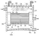
- FIG. 3 is a schematic drawing in section and in elevation showing another example of a filtration system having at least one array of hollow fiber membranes combined with multiple energy sources operable to clean exterior portions of the associated filter media in accordance with teachings of the present invention
- FIG. 4 is a schematic drawing in section and in elevation with portions broken away showing a filtration system having at least one array of hollow fiber membranes which may be alternately tensioned and relaxed while cleaning exterior portions of the hollow fiber membranes in accordance with teachings of the present invention
- FIG. 5 is a schematic drawing in section and in elevation with portions broken away showing a filtration system having at least one array of hollow fiber membranes in combination with air bubbling and apparatus for cleaning exterior portions of the associated filter media in accordance with teachings of the present invention.
- FIG. 6 is a schematic drawing in section and in elevation with portions broken away which shows a filtration system having at least one array of hollow fiber membranes which may be alternately tensioned and relaxed in combination with injecting air bubbles and acoustic or vibration ways to clean exterior portions of the associated filter media.
- FIGS. 1A-6 wherein like number refer to same and like parts.
- acoustic energy may be used to describe both sonic energy (generally equal to or less than 20,000 cycles per second) and ultrasonic energy (generally greater than 20,000 cycles per second). Acoustical vibration may be produced by sonic energy and/or ultrasonic energy.
- membrane may be used in this application to mean any material having openings or pores satisfactory for use in separating a process fluid into a clarified fluid stream and a concentrated fluid stream.
- Membranes satisfactory for use with filtration systems incorporating teachings of the present invention may be formed from woven materials, nonwoven materials and/or perforated plastic films.
- Various types of membranes may be used to form hollow fiber membranes based upon desired characteristics such as ability to separate liquids from gasses and the ability to separate suspended solids, colloidal matter and particulate matter from a fluid stream.
- Membrane materials may be selected with desired permeability or porosity for each application.
- hollow fiber membrane may be used to describe any generally hollow elongated tube formed from various types of membrane material. Hollow fiber membranes may also be described as “hollow fiber filter elements”, “hollow membrane tubes” and “hollow core membrane fibers”.
- Process fluid may be generally defined as a fluid stream containing liquids and/or gasses along with suspended solids, colloidal matter and/or particulate matter including, but not limited to, nanoparticles.
- Fluid permeable membranes may be used to separate various components of a process fluid into a clarified fluid and a concentrated fluid in accordance with teachings of the present invention.
- Membranes used to separate process fluids may generally be described as having an upstream side which is the side or face communicating with a process fluid. Membranes also have a downstream side or face communicating with clarified fluids removed from the process fluids.
- a hollow fiber membrane may be generally described as a hollow tube having a fluid flow path extending longitudinally therethrough. Multiple openings or pores may be formed in associated membrane material.
- the upstream side or upstream surface of a hollow fiber membrane is generally the exterior surface of the membrane material exposed to process fluids.
- the downstream side or downstream surface of a hollow fiber membrane is generally the interior surface of the membrane material.
- the flow path will generally collect clarified fluid which flows through the pores or openings in the membrane material.
- the interior surface of a hollow fiber membrane may function as the upstream side or upstream surface. However, such applications are often limited to specific types of process fluids.
- Clarified fluids may include liquids, gasses, solids, particulate matter and/or colloidal matter which has been able to pass through or permeate through openings in an associated membrane. Clarified fluids may also be referred to as “permeate” or “permeate fluids”.
- Process fluids passing over the upstream side of a membrane gradually lose associated liquids and/or gaseous components by such components permeating through openings or pores in the membrane.
- the remaining process fluid generally becomes relatively thicker with a higher concentration of solids, colloidal matter and/or particulate matter which will not pass through openings or pores in the membrane.
- the accumulation of such materials on the upstream side of a membrane may be referred to as a “retentate” or “concentrated fluid”.
- fluid may be used to include liquids, gasses or a combination of liquids and gasses.
- housing may be used to describe any container, tank, chamber, vessel, pressure vessel, cartridge, surrounding housing, frame assembly or any other structure suitable for holding an array of hollow fiber membranes in accordance with teachings of the present invention. Some housings may be open to ambient pressure or may be disposed within a reservoir holding process fluid. Other housing may be capable of holding a positive pressure or a vacuum depending upon requirements of an associated filtration process.
- Some filtration systems may be formed with a plurality of hollow fiber membranes having only one end of each hollow fiber membrane attached to a single end cap. The opposite end of the hollow fiber membranes may be sealed or closed to prevent undesired fluid flow therethrough.
- Various features of the present invention may be used with arrays of hollow fiber membranes having only one end cap or a pair of end caps.
- the filtration systems shown in FIGS. 1 A and 2 - 6 include a plurality of hollow fiber membranes 50 with opposite ends of each hollow fiber membrane 50 attached to respective end caps 42 and 44 .
- Various features of the present invention, described with respect to hollow fiber membrane array 40 may also be satisfactorily used to with hollow fiber membrane arrays attached to only a single end cap (not expressly shown). Mounting elements other than end caps 42 and 44 may be satisfactorily used.
- FIG. 1 A One example of a filtration system having an array or cluster of hollow fiber membranes is shown in FIG. 1 A.
- filtration system or fluid separation system 20 may include housing 30 with one or more hollow fiber membrane arrays 40 disposed therein.
- Hollow fiber member array 40 includes a plurality of individual hollow fiber membranes or tubes 50 attached to and bonded with respective end caps 42 and 44 .
- Various techniques may be satisfactorily used to couple respective ends of each hollow fiber membrane 50 with end caps 42 and 44 .
- Some types of end caps may be referred to as “potting heads”. See for example U.S. Pat. No. 5,445,771 entitled “Process For Preparing Hollow Fiber Separatory Devices”; U.S. Pat. No.
- Housing 30 preferably includes at least a first inlet for process fluid, a first outlet for permeate or clarified fluid and a second outlet for retentate or concentrated fluid.
- housing 30 includes process fluid inlet 22 , clarified fluid outlet 24 and retentate outlet 26 .
- fluids with increased density and any solids, scale or biological films separated from the process fluid may collect along lower portions of housing 30 . Therefore, concentrated fluid outlet 26 may be formed proximate the lower portion of housing 30 .
- Housing 30 may either be open to the atmosphere or may be capable of operating as a pressure vessel depending upon characteristics of the associated process fluid and fluid separation process.
- End cap 44 may include multiple flow paths (not expressly shown) communicating with respective fluid flow paths 62 formed within each hollow fiber membrane 50 .
- End cap 44 may function as a permeate or clarified fluid collecting manifold to direct clarified fluid flow from respective fluid flow paths 62 to conduits extending between end cap 44 and clarified fluid outlet 24 .
- end cap 42 may also function as a clarified fluid collecting manifold and may be operably coupled with an associated clarified fluid outlet (not expressly shown).
- end caps 42 and 44 may be used to maintain relatively constant tension on hollow fiber membranes 50 .
- Each hollow fiber membrane 50 may have a generally circular configuration defined in part by longitudinal axis 52 . See FIGS. 1B and 1C .
- Each hollow fiber membrane 50 may include generally cylindrical wall 54 having a plurality of pores or opening 56 disposed therein. Openings 56 preferably extend from exterior surface 58 through wall 54 to interior surface 60 . Interior surface 60 defines in part fluid flow path 62 extending generally longitudinally through each hollow fiber membrane 50 approximately parallel with longitudinal axis 52 .
- the dimensions and configurations of each pore or opening 58 may vary along wall 54 , particularly for hollow fiber membranes formed from nonwoven materials. See, for example, U.S. Pat. No. 6,770,202 entitled “Porous Membrane”.
- hollow fiber membrane 50 is shown in FIGS. 1B and 1C with a generally circular cross section relative to longitudinal axis 52 .
- the configuration of hollow fiber membranes 50 may vary substantially.
- hollow fiber membranes 50 may have oval, elliptical and/or circular cross sections depending upon the type of material used to form each hollow fiber membrane 50 .
- the type of process fluid and associated operating pressure of filtration system 20 may also vary the configuration of hollow fiber membranes 50 .
- Arrows 70 as shown in FIGS. 1B and 1C indicate the general direction of vibration energy which may be applied to hollow fiber membrane 50 in accordance with teachings of the present invention.
- the vibration energy may be produced by a mechanical energy source or an acoustic energy source. Exterior portions of hollow fiber membrane 50 immediately adjacent to oncoming acoustical energy or vibration energy may be described as leading face 72 . Exterior portions of hollow fiber membrane 50 opposite from the direction of acoustical energy or vibration may be described as trailing face 74 . Exterior portions 76 and 78 of hollow fiber membrane 50 may be described as “side faces”.
- vibration energy may have multiple effects upon exterior portions of hollow fiber membrane 50 .
- One cleaning effect includes reciprocating movement or bouncing of hollow fiber membrane 50 as represented by dotted lines 50 a and 50 b in response to vibration energy directed generally perpendicular to longitudinal axis 52 .
- a second cleaning effect includes turbulent scouring of side faces 76 and 78 .
- Vibration energy and/or acoustical energy may cause movement of process fluids, scale, solid cakes and/or biological films disposed on exterior surface 58 and may also move hollow fiber membrane 50 .
- the process fluid, scale, solids cake, biological film and hollow fiber membrane 50 may each have different rates of movement which results in lifting or removing scale, solids cake and/or biological film from leading face 72 and trailing face 74 .
- the difference in inertia or mass of the process fluid, any scale, solids and/or biological film and each hollow fiber membrane may produce leading face turbulence and trailing face turbulence in response to acoustic and/or vibration energy. Such cleaning effects promote dynamic filtration of the process fluid.
- Acoustical energy and/or vibration energy may also create shear forces between the process fluid and side faces 76 and 78 .
- the resulting shear forces may result in turbulent flow of process fluid adjacent to side faces 76 and 78 which lifts or removes any scale, solids cake and/or biological film disposed thereon.
- Arrows 80 in FIG. 1C indicate such turbulent flow.
- Cleaning effects associated with turbulent flow adjacent to side faces 76 and 78 also promote dynamic filtration of the process fluid.
- Applying vibration energy to an array of hollow fiber membranes 50 in accordance with teachings of the present invention may also result in scraping or scrubbing of adjacent exterior surfaces of hollow fiber membranes 50 . Movement of hollow fiber membranes 50 such as shown in FIG. 1C may result in multiple contacts or jostling of adjacent hollow fiber membranes 50 with each other. This third cleaning effect may promote dynamic filtration of the process fluid.
- alternatively relaxing and tensioning hollow fiber membranes 50 may result in exterior portions of adjacent hollow fiber membranes 50 scraping or scouring one another which provides a fourth cleaning effect especially when acoustical energy and/or vibration energy is being applied. See FIGS. 4 and 6 .
- Teachings of the present invention may be used to provide at least four (4) effects to clean or inhibit deposits of scale, solids cake and/or biological films on exterior portions of hollow fiber membranes 50 .
- FIGS. 2-6 Various examples of apparatus and methods for cleaning exterior portions (upstream surfaces) of hollow fiber membranes during dynamic filtration in accordance with teachings of the present invention are shown in FIGS. 2-6 .
- Filtration system 120 a as shown in FIG. 2 combines various features of previously described filtration system 20 with mechanical vibration system 100 .
- the present invention may be used with housings having various configurations.
- housing 30 a may be described as having a generally cylindrical configuration defined in part by wall 32 , first end closure 34 and second end closure 36 . Cylindrical wall 32 and end closures 34 and 36 may be satisfactorily formed from a wide variety of materials.
- Mechanical vibration system 100 preferably includes vibration driver 102 and at least one connector 104 operable to transmit vibration energy from driver 102 to end closure 34 .
- Connector 104 may be a plunger, piston rod or motor driven shaft.
- Vibration driver 102 may be generally described as a linear, reciprocating mechanical driver. Vibration driver 102 may include an air powered vibration generator, a motor (electrical or hydraulic) powered vibration generator or any other mechanism satisfactory for producing linear reciprocating motion of connector 104 .
- End closure 34 may sometimes be described as a diaphragm operable to transmit vibration energy represented by waves 70 a .
- Hollow fiber membrane array 40 is preferably aligned with end closure 34 such that vibration energy may be directed substantially normal to or perpendicular with leading face 72 of each hollow fiber membrane 50 .
- End cap 42 and 44 may be securely attached with interior portions of wall 32 to maintain substantially constant tension on hollow fiber membranes 50 .
- Vibration waves 70 a may be projected along approximately the full length of each hollow fiber membrane 50 .
- end caps 42 and 44 may be generally described as “stationary mounting heads” which cooperate with each other to maintain a predetermined amount of tension on associated hollow fiber membranes 50 .
- mechanical vibration system 100 may include control system 110 .
- Control system 110 may include one or more permeate flow rate sensors 112 operably coupled with permeate outlet 24 .
- Flow rate sensor 112 may be used to detect permeate rate from outlet 24 and any changes in permeate flow rate.
- Sensor 112 communicates this information to logic control device 114 which may include instructions to increase or decrease the amplitude and frequency of vibration energy produced by vibration driver 102 to increase or decrease cleaning of associated hollow fiber membranes 50 as appropriate.
- flow rate sensor 112 may detect the resulting increased permeate fluid flow rate and signal this change to logic control device 114 .
- Logic control device 114 may then send a signal to vibration driver 102 to change the frequency and/or amplitude of vibration energy applied to exterior surfaces of hollow fiber membranes 50 to reduce the unnecessary energy use. Such changes may be made continuously or at selected time intervals.
- flow rate sensors (not expressly shown) may also be coupled with process fluid inlet 22 and retentenate outlet 26 . Information from these sensors may also be communicated to logic control device 114 to regulate the amplitude and frequency of vibration energy produced by vibration driver 102 .
- secondary vibration driver or vibration canceling 106 may be operably engaged with end closure 36 .
- At least one connector 108 may transmit vibration energy from driver 106 to end closure 34 .
- Secondary vibration driver 106 and connector 108 may include similar features and characteristics as previously described with respect to vibration driver 102 and connector 104 .
- control system 110 may send an appropriate signal to secondary vibration canceling driver 106 to actively equalize, cancel or reduce any vibration waves reflected from enclosure 36 .
- Relatively small waves 70 b represent the effect of secondary vibration driver 106 equalizing, canceling or reducing primary vibration energy reflected from end closure 36 .
- control system 110 may send signals from logic control device 114 to both primary vibration driver 102 and secondary vibration driver 106 .
- One or more sensors may be disposed on end closure 36 to detect primary vibration waves 70 a and provide an appropriate signal to control system 110 .
- any changes in the amplitude and/or frequency of primary vibration waves 70 a or initiation of vibration waves 70 a may result in real-time changes represented by secondary vibration waves 70 b.
- Vibration energy whether mechanical or acoustical will generally be more effective if the vibration energy is applied uniformly to exterior portions of all hollow fiber membranes disposed within a housing.
- the use of vibration canceling driver 106 and control system 110 in accordance with teachings of the present invention may result in substantial reduction and/or elimination of interference waves 70 b associated with vibration energy returning from or bouncing back from end closure 36 .
- vibration energy absorbing material may also be disposed within selected portions of a housing to substantially reduce or eliminate undesired return or bounce back of primary vibration energy.
- the present invention allows primary vibration energy (vibration waves 70 a ) to produce optimum cleaning and/or unclogging of exterior portions of associated hollow fiber membranes 50 .
- one or more sensing devices may be located at various positions within housing 30 a to detect and measure primary vibration waves 70 a . Generally such sensing devices will be located opposite from primary vibration driver 102 . This location will often be at the greatest distance within housing 30 a from primary vibration driver 102 .
- One or more secondary vibration drivers 106 may be located approximately opposite from primary vibration driver 102 .
- Control system 110 may be used to continuously interpret data from associated sensors and provide operating instructions to secondary vibration driver 106 to adjust its associated vibration energy output to actively cancel, equalize or substantially reduce primary vibration waves 70 a as they reach end closure 36 .
- the previous comments have been made with respect to mechanical vibration driver such as shown in FIG. 2 .
- a primary electrical vibration driver and a secondary electrical vibration driver may also be used to equalize, cancel or reduce primary vibration waves in accordance with teachings of the present invention.
- Filtration system 120 b combines various features of previously described filtration system 20 with electrical vibration system 130 having an array of piezo-electric transducers 132 .
- piezo-electric transducers 132 may be used to produce sonic energy in the frequency range of approximately fifteen (15) to twenty thousand (20,000) cycles per second to induce vibration waves 70 a .
- piezo-electric transducers 132 may be used to produce ultrasonic energy (greater than 20,000 cycles per second).
- the sonic energy may have a generally constant frequency or a variable frequency as appropriate for optimum cleaning of associated hollow fiber membranes 50 .
- the amplitude and frequency of the acoustic energy may be adjusted to produce desired vibration of hollow fiber membranes 50 .
- the amplitude and/or frequency of sonic signals produced by transducers 132 may remain constant.
- the amplitude and frequency may be intermittently or continuously variable depending upon requirements of an associated dynamic filtration process.
- a wide variety of electrical energy drivers may be satisfactorily used with primary filtration system 120 b .
- the present invention is not limited to piezo-electric transducers 132 .
- Housing 30 b may have various configurations, including generally cylindrical wall 32 . However, end closure 34 b may be modified to accommodate attachment of piezo-electric transducers 132 . End closure 36 b or various other satisfactory end enclosures may be installed within housing 30 b . For some applications, one or more layers of vibration energy absorbing material 134 may be disposed on interior portions of end closure 36 b opposite from transducers 132 . Vibration energy absorbing material 134 may be located and tuned for optimum results. As a result of attaching vibration energy absorbing material 134 with end closure 36 b , the amplitude of waves 70 b reflected from end closure 36 b may be substantially reduced or eliminated.
- an array of piezo-electric transducers may be attached with end closure 36 b for use in canceling vibration waves 70 a as previously described with respect to filtration system 120 a .
- a control system (not expressly shown) may also be used to vary the amplitude and/or frequency of primary sonic energy produced by transducers 132 .
- housing 30 b may include one or more vents 38 which are open to ambient air pressure exterior to housing 30 .
- piezo-electric transducers 132 may be satisfactorily used in a sealed or closed housing.
- housing 30 b or any other housing formed in accordance with teachings of the present invention may include one or more return paths (not expressly shown) to direct primary vibration waves 70 a from end closure 36 b to end closure 34 b proximate piezo-electric transducers 132 .
- the returned paths may be separate passageways disposed on the exterior of housing 30 b .
- the return paths may be filled with various fluids to provide optimum return of primary vibration waves 70 a .
- return waves 70 b may be substantially reduced or eliminated.
- the returned vibration waves may be synchronized with primary vibrations waves 70 a being generated by transducers 132 .
- the efficiency of an associated primary vibration driver may be enhanced.
- one or more passageways or openings may be provided within housing 30 b to return primary vibration energy or to direct such primary vibration energy to escape from housing 30 b.
- Filtration system 120 c combines various features of the previously described filtration system 120 a with variable tensioning of hollow fiber membranes 50 .
- Housing 30 c preferably includes wall 32 c which has been modified to accommodate variable tensioning of hollow fiber membrane array 40 c .
- end caps 42 c and 44 c may be modified to allow reciprocating longitudinally movement relative to each other and adjacent portions of wall 32 c . Movement of end caps 42 c and 44 c relative to each other may vary both the length and cross section of attached hollow fiber membranes 50 .
- brackets 142 and 144 may be securely attached with adjacent portions of wall 32 c .
- End caps 42 c and 42 c may be slidably retained within respective brackets 142 and 144 .
- Various types of electrical and/or mechanical motors may be attached with respective shafts 146 , extending from end caps 42 c and 44 c through respective openings 148 in adjacent portions of wall 32 c .
- each shaft 146 may include hollow flow path 24 c extending therethrough to allow communication of clarified fluid or permeate from fluid flow path 62 of each hollow fiber membrane 50 .
- Vibration wave a 70 a produced by vibration driver 102 may be combined with physical interference or physical scouring associated with alternately tensioning and relaxing hollow fiber membrane 50 .
- Variable tensioning plus applying vibration energy generally perpendicular to longitudinal axis 52 of hollow fiber membranes 50 will increase shaking and shearing actions to remove any scale, solids cake and/or biological films from exterior portions of hollow fiber membranes 50 .
- Filtration system 120 may also include previously described control system 110 and vibration canceling driver 106 .
- variable tensioning of hollow fiber membranes 50 may be satisfactorily used with an electrical vibration system.
- Fluid filtration system 120 d combines various features previously described filtration system 120 a along with a gas bubbling system 150 .
- Housing 30 e may include various features as previously described with respect to housing 30 a . However, for embodiments such as shown in FIG. 5 , housing 30 e may be oriented with end closures 34 and 36 , extending generally vertically relative to wall 32 d . End cap 42 d may be modified to accommodate gas flow from manifold 152 .
- Gas bubbling system 150 may include a source 154 of relatively high pressure gas.
- One or more regulators 156 may be used to control the flow of gas from source 154 to manifold 152 .
- One or more conduits 158 may be used to couple regulator 156 with manifold 152 .
- Insert gas source 154 may provide nitrogen, air and any other suitable gas to manifold 152 .
- Vibration waves 70 a from vibration driver 102 may be projected generally perpendicular with respect to the exterior portions of hollow fiber membranes 50 .
- Gas bubbles from manifold 152 may flow generally parallel with hollow fiber membranes 50 . The gas bubbles cooperate with the perpendicular vibration waves to increase scouring or cleaning of exterior portions of hollow fiber membranes 50 .
- Filtration system 120 e as shown in FIG. 6 combines various features of previously described filtration systems 120 c and 120 d .
- Exterior portions of hollow fiber membranes 50 may be cleaned by using a combination of vibration energy produced by vibration device 102 , gas bubbles from manifold 152 flowing generally parallel with exterior portions of hollow fiber membranes 50 and reciprocating movement of end cap 44 c to produce alternative tensioning and relaxing of attached hollow fiber membranes 50 .
- the removal of scale, solids cake and/or biological films may be further enhanced by using water jets (not expressly shown) or other suitable pumps (not expressly shown) to direct fluid flow generally parallel with exterior portions of hollow fiber membranes 50 .
- Such fluid flow may be used either intermittently or continuously.
- such fluid flow may be used in combination with bubbles from manifold 52 , alternatively tensioning and relaxing hollow fiber membranes 50 and/or applying vibration energy thereto.
- process fluids may be directed through one or more inlet tubes (not expressly shown) to locations disposed within each hollow fiber membrane array 40 .
- inbound movement or flow of process fluid may be used to assist with transport of any scale, solids cake and/or biological films removed from exterior portions of hollow fiber membranes 50 by any of the previously described cleaning effects.
- Filtration systems 120 a , 120 b , 120 c , 120 d and 120 e may be used to treat a wide variety of process fluids.
- Such filtration systems may include one or more arrays of hollow fiber membranes.
- the arrays may be mounted in side by side relationships in a housing or in a cassette (not expressly shown).
- the cassette may be placed in a relatively open or unrestricted reservoir.
- Such cassettes may also be placed in and removed from pressurized or closed housings.
- one end of the hollow fiber membranes may be attached to a mounting element such as an end cap.
- the hollow fiber membranes may hang from the one mounting element.
- both ends of the hollow fiber membranes may be attached to respective mounting elements such as a pair of end caps spaced from each other.
- the mounting elements may apply relatively preset or constant tension to the associated hollow fiber membranes.
- both ends of the hollow fiber membranes may be attached to mounting elements operable to apply variable tension to the associated hollow fiber membranes. The amount of tension may be varied substantially continuously or may be varied intermittently during an associated dynamic filtration process.
- Previously described filtration systems 120 a , 120 b , 120 c , 120 d and 120 e may be further modified to improve associated dynamic filtration processes by applying a source of vacuum to associated clarified fluid outlets and/or applying pressure to associated process fluid inlets.
- Increasing the differential pressure applied to exterior portions of hollow fiber membranes may be used to increase the flow rate of clarified fluid or permeate through associated membrane walls 54 .
- the amount of differential pressure may be regulated to leave selected retentate components on exterior portions of the associated hollow fiber membranes 50 .
- Filtration systems incorporating teachings of the present invention may be used for the following applications.
Landscapes
- Chemical & Material Sciences (AREA)
- Chemical Kinetics & Catalysis (AREA)
- Life Sciences & Earth Sciences (AREA)
- Hydrology & Water Resources (AREA)
- Engineering & Computer Science (AREA)
- Environmental & Geological Engineering (AREA)
- Water Supply & Treatment (AREA)
- Organic Chemistry (AREA)
- Separation Using Semi-Permeable Membranes (AREA)
Abstract
A filtration system is provided with hollow membrane filter elements operable to remove solids, particulate and colloidal matter from a process fluid. Acoustic, vibration and ultrasonic energy may be used to clean exterior portions of the hollow membrane filter elements to allow substantially continuous filtration of process fluids. The filtration system may be satisfactorily used with process fluids having a relatively high concentrations of solids, particulate and colloidal matter.
Description
This application claims priority to U.S. Provisional Application Ser. No. 60/509,838, filed Oct. 7, 2003, and entitled “Cleaning Hollow Core Membrane Fibers Using Vibration.”
This application claims priority to U.S. Provisional Application Ser. No. 60/509,837, filed Oct. 7, 2003, and entitled “Cleaning Hollow Core Membrane Fibers Using Acoustic Vibration Enhanced By Sound Cancellation Or Absorption.”
This application is related to co-pending application Ser. No. 10/903,932 filed Jul. 30, 2004, and entitled “Filtration system with enhanced cleaning and dynamic fluid separation and Co-pending application Ser. No. 10/902,771 filed Jul. 30, 2004, and entitled “Filtration system and dynamic fluid separation method”/
The present invention is related in general to the field of fluid separation, and more particularly, to fluid separation systems having hollow fiber membranes or tubes combined with enhanced cleanings of such filter elements.
The filtration industry is continuously looking for apparatus and methods to perform filtration for sustained periods, even when processing fluids with high amounts of solids and/or colloidal materials. A wide variety of filter media designs and configurations have been used in attempts to provide continuous filtration processes. This goal has led to several known techniques for continuously inhibiting the buildup of scale, solids cake or films which tend to deposit on and block passage of desired fluid flow through associated filter media. In some cases, these techniques are used intermittently, to perform what is called cyclic cleaning of filter media surfaces, usually when an associated filtration process has been suspended for such cleaning.
Filtration systems generally require periodic removal of clogged filter media or cleaning of filter media to remove particulate matter, solids and/or colloidal matter. Such materials often build up on upstream surfaces of filter media and reduce the rate permeate or clarified fluids may flow through the filter media. Examples include buildup of mineral scale, bridged solids cake or biological films. Intermittently stopping a filtration process to manually or chemically clean upstream surfaces of filter media or to backwash clarified fluid through associated filter media is generally inefficient, labor-intensive and expensive.
Various batch cleaning and manual cleaning techniques have been used, such as backwashing, chemical washing or hand scrubbing of filter media. Other methods for inhibiting or alleviating scaling, caking and/or filming of filter media include application of relatively violent vibration of an entire filtration device parallel to the planes of a plurality of stacked filter media and directing air or other gaseous bubbles under pressure parallel with associated filter media.
U.S. Pat. Nos. 4,872,988; 4,952,317; 5,014,564; 5,725,767 and 6,322,698 teach relatively violent reciprocating, torsional vibration of an entire filtration devices parallel to the planes of associated stacked membranes. The patents teach shaking enclosing vessels, stacked filter leaves or plate frame filters along with associated plumbing and connecting devices, and the contained process fluid. Relatively high construction costs may be required to build structures that can withstand these constant reciprocating motions and high amounts of energy often required to generate such motion to provide commercially viable amounts of upstream membrane cleaning, for applications of sufficient value to justify the costs.
Another method used to inhibit membrane clogging by caking, scaling or filming, is the use of air bubbling. U.S. Pat. No. 6,287,467 teaches cleaning parallel mounted flat leaf elements via air bubbling. The associated leaf filter elements generally require maintenance of uniform, structurally braced spacing between each filter leaf element to provide access for air bubbles to all membrane surfaces. The rigidly held membrane surfaces may provide a highly stable platform on which solids cake may build up which the air bubbles can no longer remove such that manual cleaning may be required.
Vibratory techniques such as ultrasonic excitation have been used for sensing membrane conditions, or applied to a single membrane surface, such as in small-scale laboratory explorations. U.S. Pat. No. 6,708,957; RE 37,549; 6,245,239 and 5,910,250 show the use of bubbles directed under pressure between and along upstream surfaces of clusters or skeins of hollow fiber membranes. Materials used to form hollow fiber membranes often attract the growth of scale and/or biological films such that periodic manual cleaning and/or chemical cleaning of such filter media may still be required even when bubbling techniques are used.
In accordance with teachings of the present invention, a filtration system may be provided with at least one array or cluster of hollow fiber membranes which may be cleaned to inhibit or remove the buildup of solids cake, mineral scale and/or biological films without requiring stopping of an associated filtration process. One aspect of the invention includes either continuously or intermittently removing scale, solids cake, biological films, particulate and/or colloidal matter from exterior portions of hollow fiber membranes to maximize fluid flow through pores or openings in associated membranes and to provide substantially continuous flow of clarified fluid from an associated filtration system.
One aspect of the present invention includes removing or inhibiting build up of mineral scale, solids cake and/or biological films that provide dynamic filtration when one or more arrays of hollow fiber membranes are used as the filter media in a high capacity, commercial filtration system. Dynamic filtration may be generally defined as the use of filter media capable of substantially continuous operation with either no interruption of an associated filtration process or substantially reduced frequency of cleaning associated filter media that interrupts and otherwise substantially continuous filtration process.
Apparatus and methods incorporating teachings of the present invention may be used either continuously or intermittently to provide dynamic filtration depending upon characteristics of an associated filtration system, hollow fiber membranes, process fluid and desired clarified fluid flow rates. A wide variety of electrical, mechanical and electro-mechanical devices may be use to produce vibration energy in accordance with teachings of the present invention. Energy in the form of mechanically induced vibration and/or acoustically induced vibration may be used to clean hollow fiber membranes in accordance with teachings of the present invention. Sonic energy between approximately 15 and 20,000 cycles per second and ultrasonic energy generally greater than 20,000 cycles per second may be use to generate acoustically induced vibration in accordance with teachings of the present invention.
For some applications vibration energy may be equalized, redirected or absorbed to minimize return or bounce back of vibration waves in a closed housing. Undesired return or bounce back of vibration waves may interfere with or diminish the effectiveness of primary vibration energy to produce a desired cleaning effect. Vibration energy absorbing material may be placed at selected locations within a housing to prevent or minimize undesired return of vibration waves. Also, vibration canceling drivers (mechanical or electronic) may be used to prevent or minimize undesired return of vibration waves. Various flow paths may be provided in a closed housing to return primary vibration energy to a location proximate the vibration energy source to enhance rather than diminish effectiveness of the primary vibration energy.
A more complete and thorough understanding of the present embodiments and advantages thereof may be acquired by referring to the following description taken in conjunction with the accompanying drawings, in which like reference numbers indicate like features, and wherein:
Preferred embodiments of the invention and its advantages are best understood by reference to FIGS. 1A-6 wherein like number refer to same and like parts.
The term “acoustic” energy may be used to describe both sonic energy (generally equal to or less than 20,000 cycles per second) and ultrasonic energy (generally greater than 20,000 cycles per second). Acoustical vibration may be produced by sonic energy and/or ultrasonic energy.
The term “membrane” may be used in this application to mean any material having openings or pores satisfactory for use in separating a process fluid into a clarified fluid stream and a concentrated fluid stream. Membranes satisfactory for use with filtration systems incorporating teachings of the present invention may be formed from woven materials, nonwoven materials and/or perforated plastic films. Various types of membranes may be used to form hollow fiber membranes based upon desired characteristics such as ability to separate liquids from gasses and the ability to separate suspended solids, colloidal matter and particulate matter from a fluid stream. Membrane materials may be selected with desired permeability or porosity for each application.
The term “hollow fiber membrane” may be used to describe any generally hollow elongated tube formed from various types of membrane material. Hollow fiber membranes may also be described as “hollow fiber filter elements”, “hollow membrane tubes” and “hollow core membrane fibers”.
Process fluid may be generally defined as a fluid stream containing liquids and/or gasses along with suspended solids, colloidal matter and/or particulate matter including, but not limited to, nanoparticles. Fluid permeable membranes may be used to separate various components of a process fluid into a clarified fluid and a concentrated fluid in accordance with teachings of the present invention. Membranes used to separate process fluids may generally be described as having an upstream side which is the side or face communicating with a process fluid. Membranes also have a downstream side or face communicating with clarified fluids removed from the process fluids.
A hollow fiber membrane may be generally described as a hollow tube having a fluid flow path extending longitudinally therethrough. Multiple openings or pores may be formed in associated membrane material. The upstream side or upstream surface of a hollow fiber membrane is generally the exterior surface of the membrane material exposed to process fluids. The downstream side or downstream surface of a hollow fiber membrane is generally the interior surface of the membrane material. The flow path will generally collect clarified fluid which flows through the pores or openings in the membrane material. For some applications the interior surface of a hollow fiber membrane may function as the upstream side or upstream surface. However, such applications are often limited to specific types of process fluids.
Clarified fluids may include liquids, gasses, solids, particulate matter and/or colloidal matter which has been able to pass through or permeate through openings in an associated membrane. Clarified fluids may also be referred to as “permeate” or “permeate fluids”.
Process fluids passing over the upstream side of a membrane gradually lose associated liquids and/or gaseous components by such components permeating through openings or pores in the membrane. The remaining process fluid generally becomes relatively thicker with a higher concentration of solids, colloidal matter and/or particulate matter which will not pass through openings or pores in the membrane. The accumulation of such materials on the upstream side of a membrane may be referred to as a “retentate” or “concentrated fluid”.
The term “fluid” may be used to include liquids, gasses or a combination of liquids and gasses.
The term “housing” may be used to describe any container, tank, chamber, vessel, pressure vessel, cartridge, surrounding housing, frame assembly or any other structure suitable for holding an array of hollow fiber membranes in accordance with teachings of the present invention. Some housings may be open to ambient pressure or may be disposed within a reservoir holding process fluid. Other housing may be capable of holding a positive pressure or a vacuum depending upon requirements of an associated filtration process.
To achieve sufficient surface area for high capacity, commercial filtration applications, multiple flat sheets of filter membranes are frequently collected together within a single filtration device. Various techniques may be used to combine flat sheet filter membranes such as parallel stacks mounted either horizontally or vertically or winding relatively long sheets of flat filter membrane material into various spiral configurations. To achieve sufficient surface area for high capacity, commercial scale filtration systems, a plurality of hollow fiber membranes may be bundled together in parallel arrays or clusters. Such arrays or clusters may sometimes be referred to as “skeins”.
Some filtration systems may be formed with a plurality of hollow fiber membranes having only one end of each hollow fiber membrane attached to a single end cap. The opposite end of the hollow fiber membranes may be sealed or closed to prevent undesired fluid flow therethrough. Various features of the present invention may be used with arrays of hollow fiber membranes having only one end cap or a pair of end caps.
The filtration systems shown in FIGS. 1A and 2-6, include a plurality of hollow fiber membranes 50 with opposite ends of each hollow fiber membrane 50 attached to respective end caps 42 and 44. Various features of the present invention, described with respect to hollow fiber membrane array 40, may also be satisfactorily used to with hollow fiber membrane arrays attached to only a single end cap (not expressly shown). Mounting elements other than end caps 42 and 44 may be satisfactorily used.
One example of a filtration system having an array or cluster of hollow fiber membranes is shown in FIG. 1A. For this example filtration system or fluid separation system 20 may include housing 30 with one or more hollow fiber membrane arrays 40 disposed therein. Hollow fiber member array 40 includes a plurality of individual hollow fiber membranes or tubes 50 attached to and bonded with respective end caps 42 and 44. Various techniques may be satisfactorily used to couple respective ends of each hollow fiber membrane 50 with end caps 42 and 44. Some types of end caps may be referred to as “potting heads”. See for example U.S. Pat. No. 5,445,771 entitled “Process For Preparing Hollow Fiber Separatory Devices”; U.S. Pat. No. 6,656,356 entitled “Aerated Immersed Membrane System”; U.S. Pat. No. 6,685,832 entitled “Method Of Potting Hollow Fiber Membranes” and U.S. Pat. No. 6,739,459 entitled “Filter Element Including Bonded End Caps And Support Core”.
Each hollow fiber membrane 50 may have a generally circular configuration defined in part by longitudinal axis 52. See FIGS. 1B and 1C . Each hollow fiber membrane 50 may include generally cylindrical wall 54 having a plurality of pores or opening 56 disposed therein. Openings 56 preferably extend from exterior surface 58 through wall 54 to interior surface 60. Interior surface 60 defines in part fluid flow path 62 extending generally longitudinally through each hollow fiber membrane 50 approximately parallel with longitudinal axis 52. For many applications the dimensions and configurations of each pore or opening 58 may vary along wall 54, particularly for hollow fiber membranes formed from nonwoven materials. See, for example, U.S. Pat. No. 6,770,202 entitled “Porous Membrane”.
For purposes of illustrating various features of the present invention, hollow fiber membrane 50 is shown in FIGS. 1B and 1C with a generally circular cross section relative to longitudinal axis 52. However, the configuration of hollow fiber membranes 50 may vary substantially. For example, hollow fiber membranes 50 may have oval, elliptical and/or circular cross sections depending upon the type of material used to form each hollow fiber membrane 50. The type of process fluid and associated operating pressure of filtration system 20 may also vary the configuration of hollow fiber membranes 50.
As shown in FIG. 1C , vibration energy may have multiple effects upon exterior portions of hollow fiber membrane 50. One cleaning effect includes reciprocating movement or bouncing of hollow fiber membrane 50 as represented by dotted lines 50 a and 50 b in response to vibration energy directed generally perpendicular to longitudinal axis 52. A second cleaning effect includes turbulent scouring of side faces 76 and 78.
Vibration energy and/or acoustical energy may cause movement of process fluids, scale, solid cakes and/or biological films disposed on exterior surface 58 and may also move hollow fiber membrane 50. The process fluid, scale, solids cake, biological film and hollow fiber membrane 50 may each have different rates of movement which results in lifting or removing scale, solids cake and/or biological film from leading face 72 and trailing face 74. The difference in inertia or mass of the process fluid, any scale, solids and/or biological film and each hollow fiber membrane may produce leading face turbulence and trailing face turbulence in response to acoustic and/or vibration energy. Such cleaning effects promote dynamic filtration of the process fluid.
Acoustical energy and/or vibration energy may also create shear forces between the process fluid and side faces 76 and 78. The resulting shear forces may result in turbulent flow of process fluid adjacent to side faces 76 and 78 which lifts or removes any scale, solids cake and/or biological film disposed thereon. Arrows 80 in FIG. 1C indicate such turbulent flow. Cleaning effects associated with turbulent flow adjacent to side faces 76 and 78 also promote dynamic filtration of the process fluid.
Applying vibration energy to an array of hollow fiber membranes 50 in accordance with teachings of the present invention may also result in scraping or scrubbing of adjacent exterior surfaces of hollow fiber membranes 50. Movement of hollow fiber membranes 50 such as shown in FIG. 1C may result in multiple contacts or jostling of adjacent hollow fiber membranes 50 with each other. This third cleaning effect may promote dynamic filtration of the process fluid.
As discussed later in more detail, alternatively relaxing and tensioning hollow fiber membranes 50 may result in exterior portions of adjacent hollow fiber membranes 50 scraping or scouring one another which provides a fourth cleaning effect especially when acoustical energy and/or vibration energy is being applied. See FIGS. 4 and 6 . Teachings of the present invention may be used to provide at least four (4) effects to clean or inhibit deposits of scale, solids cake and/or biological films on exterior portions of hollow fiber membranes 50.
Most commercial large scale filtrations systems which contain either multiple flat sheets of membrane material or multiple arrays of hollow fiber membranes must be periodically cleaned to remove solids cake, mineral scale and/or biological films from upstream surfaces of associated filter media. Various examples of apparatus and methods for cleaning exterior portions (upstream surfaces) of hollow fiber membranes during dynamic filtration in accordance with teachings of the present invention are shown in FIGS. 2-6 .
Vibration waves 70 a may be projected along approximately the full length of each hollow fiber membrane 50. For embodiments such as shown in FIG. 2 end caps 42 and 44 may be generally described as “stationary mounting heads” which cooperate with each other to maintain a predetermined amount of tension on associated hollow fiber membranes 50.
For some applications mechanical vibration system 100 may include control system 110. Control system 110 may include one or more permeate flow rate sensors 112 operably coupled with permeate outlet 24. Flow rate sensor 112 may be used to detect permeate rate from outlet 24 and any changes in permeate flow rate. Sensor 112 communicates this information to logic control device 114 which may include instructions to increase or decrease the amplitude and frequency of vibration energy produced by vibration driver 102 to increase or decrease cleaning of associated hollow fiber membranes 50 as appropriate.
When the increase vibration energy has removed any scale, solid cakes and/or biological materials from the exterior portions of hollow fiber membranes 50, flow rate sensor 112 may detect the resulting increased permeate fluid flow rate and signal this change to logic control device 114. Logic control device 114 may then send a signal to vibration driver 102 to change the frequency and/or amplitude of vibration energy applied to exterior surfaces of hollow fiber membranes 50 to reduce the unnecessary energy use. Such changes may be made continuously or at selected time intervals. For some applications, flow rate sensors (not expressly shown) may also be coupled with process fluid inlet 22 and retentenate outlet 26. Information from these sensors may also be communicated to logic control device 114 to regulate the amplitude and frequency of vibration energy produced by vibration driver 102.
For some applications secondary vibration driver or vibration canceling 106 may be operably engaged with end closure 36. At least one connector 108 may transmit vibration energy from driver 106 to end closure 34. Secondary vibration driver 106 and connector 108 may include similar features and characteristics as previously described with respect to vibration driver 102 and connector 104. When vibration waves 70 a reach end closure 36 opposite from vibration driver 102, control system 110 may send an appropriate signal to secondary vibration canceling driver 106 to actively equalize, cancel or reduce any vibration waves reflected from enclosure 36. Relatively small waves 70 b, as shown in FIG. 2 , represent the effect of secondary vibration driver 106 equalizing, canceling or reducing primary vibration energy reflected from end closure 36.
For some applications control system 110 may send signals from logic control device 114 to both primary vibration driver 102 and secondary vibration driver 106. One or more sensors (not expressly shown) may be disposed on end closure 36 to detect primary vibration waves 70 a and provide an appropriate signal to control system 110. As a result, any changes in the amplitude and/or frequency of primary vibration waves 70 a or initiation of vibration waves 70 a may result in real-time changes represented by secondary vibration waves 70 b.
Vibration energy whether mechanical or acoustical will generally be more effective if the vibration energy is applied uniformly to exterior portions of all hollow fiber membranes disposed within a housing. The use of vibration canceling driver 106 and control system 110 in accordance with teachings of the present invention may result in substantial reduction and/or elimination of interference waves 70 b associated with vibration energy returning from or bouncing back from end closure 36. As discussed later with respect to filtration system 120 b in FIG. 3 , vibration energy absorbing material may also be disposed within selected portions of a housing to substantially reduce or eliminate undesired return or bounce back of primary vibration energy. As a result, the present invention allows primary vibration energy (vibration waves 70 a) to produce optimum cleaning and/or unclogging of exterior portions of associated hollow fiber membranes 50.
The following methods and techniques may be used in accordance with teachings of the present invention to reduce, continuously cancel, absorb or redirect primary vibration energy such energy arrives at portions of an associated housing generally located opposite from an associated primary vibration driver. As previously noted, one or more sensing devices may be located at various positions within housing 30 a to detect and measure primary vibration waves 70 a. Generally such sensing devices will be located opposite from primary vibration driver 102. This location will often be at the greatest distance within housing 30 a from primary vibration driver 102. One or more secondary vibration drivers 106 may be located approximately opposite from primary vibration driver 102. Control system 110 may be used to continuously interpret data from associated sensors and provide operating instructions to secondary vibration driver 106 to adjust its associated vibration energy output to actively cancel, equalize or substantially reduce primary vibration waves 70 a as they reach end closure 36. The previous comments have been made with respect to mechanical vibration driver such as shown in FIG. 2 . However, a primary electrical vibration driver and a secondary electrical vibration driver may also be used to equalize, cancel or reduce primary vibration waves in accordance with teachings of the present invention.
The amplitude and frequency of the acoustic energy may be adjusted to produce desired vibration of hollow fiber membranes 50. For some applications the amplitude and/or frequency of sonic signals produced by transducers 132 may remain constant. For other applications the amplitude and frequency may be intermittently or continuously variable depending upon requirements of an associated dynamic filtration process. A wide variety of electrical energy drivers may be satisfactorily used with primary filtration system 120 b. The present invention is not limited to piezo-electric transducers 132.
For other applications, an array of piezo-electric transducers (not expressly shown) may be attached with end closure 36 b for use in canceling vibration waves 70 a as previously described with respect to filtration system 120 a. A control system (not expressly shown) may also be used to vary the amplitude and/or frequency of primary sonic energy produced by transducers 132. For the embodiment shown in FIG. 3 , housing 30 b may include one or more vents 38 which are open to ambient air pressure exterior to housing 30. For other applications piezo-electric transducers 132 may be satisfactorily used in a sealed or closed housing.
For some applications housing 30 b or any other housing formed in accordance with teachings of the present invention may include one or more return paths (not expressly shown) to direct primary vibration waves 70 a from end closure 36 b to end closure 34 b proximate piezo-electric transducers 132. The returned paths may be separate passageways disposed on the exterior of housing 30 b. The return paths may be filled with various fluids to provide optimum return of primary vibration waves 70 a. As a result, return waves 70 b may be substantially reduced or eliminated. The returned vibration waves may be synchronized with primary vibrations waves 70 a being generated by transducers 132. Also, by returning substantial amounts of primary vibration waves 70 a, the efficiency of an associated primary vibration driver may be enhanced. For other applications one or more passageways or openings may be provided within housing 30 b to return primary vibration energy or to direct such primary vibration energy to escape from housing 30 b.
For some applications, brackets 142 and 144 may be securely attached with adjacent portions of wall 32 c. End caps 42 c and 42 c may be slidably retained within respective brackets 142 and 144. Various types of electrical and/or mechanical motors (not expressly shown) may be attached with respective shafts 146, extending from end caps 42 c and 44 c through respective openings 148 in adjacent portions of wall 32 c. For some applications, each shaft 146 may include hollow flow path 24 c extending therethrough to allow communication of clarified fluid or permeate from fluid flow path 62 of each hollow fiber membrane 50.
Vibration wave a 70 a produced by vibration driver 102 may be combined with physical interference or physical scouring associated with alternately tensioning and relaxing hollow fiber membrane 50. Variable tensioning plus applying vibration energy generally perpendicular to longitudinal axis 52 of hollow fiber membranes 50 will increase shaking and shearing actions to remove any scale, solids cake and/or biological films from exterior portions of hollow fiber membranes 50. Filtration system 120 may also include previously described control system 110 and vibration canceling driver 106. Also, variable tensioning of hollow fiber membranes 50 may be satisfactorily used with an electrical vibration system.
Vibration waves 70 a from vibration driver 102 may be projected generally perpendicular with respect to the exterior portions of hollow fiber membranes 50. Gas bubbles from manifold 152 may flow generally parallel with hollow fiber membranes 50. The gas bubbles cooperate with the perpendicular vibration waves to increase scouring or cleaning of exterior portions of hollow fiber membranes 50.
For some applications the removal of scale, solids cake and/or biological films may be further enhanced by using water jets (not expressly shown) or other suitable pumps (not expressly shown) to direct fluid flow generally parallel with exterior portions of hollow fiber membranes 50. Such fluid flow may be used either intermittently or continuously. Also, such fluid flow may be used in combination with bubbles from manifold 52, alternatively tensioning and relaxing hollow fiber membranes 50 and/or applying vibration energy thereto. For still other applications process fluids may be directed through one or more inlet tubes (not expressly shown) to locations disposed within each hollow fiber membrane array 40. As a result, inbound movement or flow of process fluid may be used to assist with transport of any scale, solids cake and/or biological films removed from exterior portions of hollow fiber membranes 50 by any of the previously described cleaning effects.
For some applications one end of the hollow fiber membranes may be attached to a mounting element such as an end cap. The hollow fiber membranes may hang from the one mounting element. For other applications both ends of the hollow fiber membranes may be attached to respective mounting elements such as a pair of end caps spaced from each other. The mounting elements may apply relatively preset or constant tension to the associated hollow fiber membranes. For still other applications both ends of the hollow fiber membranes may be attached to mounting elements operable to apply variable tension to the associated hollow fiber membranes. The amount of tension may be varied substantially continuously or may be varied intermittently during an associated dynamic filtration process.
Previously described filtration systems 120 a, 120 b, 120 c, 120 d and 120 e may be further modified to improve associated dynamic filtration processes by applying a source of vacuum to associated clarified fluid outlets and/or applying pressure to associated process fluid inlets. Increasing the differential pressure applied to exterior portions of hollow fiber membranes may be used to increase the flow rate of clarified fluid or permeate through associated membrane walls 54. The amount of differential pressure may be regulated to leave selected retentate components on exterior portions of the associated hollow fiber membranes 50.
Filtration systems incorporating teachings of the present invention may be used for the following applications.
Applications in water and wastewater treatment for municipal purposes such as:
drinking water treatment;
reverse osmosis reject concentration;
reclaimed water treatment;
primary and secondary wastewater treatment; and
primary and secondary wastewater treatment sludge concentration.
Applications for water and wastewater treatment for industrial purposes such as:
ultra-pure water polishing;
process water purification;
car wash wastewater treatment and reuse;
industrial laundry wastewater treatment and reuse;
boiler feed water treatment;
industrial wastewater pretreatment;
sludge de-watering; and
scrubber effluent treatment and concentration.
Applications for water and wastewater treatment for agricultural purposes such as:
irrigation water treatment and reuse;
confined animal feeding operation wastewater treatment and reuse; and
aquaculture water treatment and reuse.
Applications in bio-manufacturing such as concentration of pharmaceutical and biotechnology products.
Applications in food and beverage processing such as:
ultra-pure water polishing;
juice concentration; and
wastewater treatment and reuse.
Applications in chemical manufacturing and process industry such as:
concentration of high solids;
calcium carbonate;
titanium dioxide;
latex emulsion and catalysts;
acid clarification;
metal hydroxide treatment;
colloidal silica filtration;
separation of othalic acid catalyst fines;
sodium hydroxide recovery; and
applications in paints and pigments industry such as white water treatment and organic and inorganic pigment washing and concentration.
Applications in the pulp and paper industry such as:
white water treatment;
box and bag plant effluent treatment;
bleach plant effluent treatment
black liquor treatment;
paper coating effluent treatment; and
green liquor treatment.
Applications in the petroleum production and refining industry such as:
recycling of petroleum;
drilling muds;
brine extraction;
cracking catalyst removal;
treatment of injection water;
produced water;
completion fluids;
process water; and
refinery wastewater treatment and reuse.
Applications in mining industry such as:
mineral clay de-watering;
red mud recovery;
mining and milling effluent treatment; and
mine tailing processing and size classification.
Other continuous filtration applications for the chemical industry, kaolin manufacture, metal casting industry, sludges from waste gas scrubbing, aluminum industry, steel industry and other materials processing industries.
Although the present invention and its advantages have been described in detail, it should be understood that various changes, substitutions and alternations can be made herein without departing from the spirit and scope of the invention as defined by the following claims.
Claims (5)
1. A filtration system operable to separate a process fluid into a clarified fluid and a concentrated fluid comprising:
a housing having at least one inlet operable to receive the process fluid;
the housing having at least a first outlet for the concentrated fluid and a second outlet for the clarified fluid;
at least one array of hollow fiber membranes disposed within the housing;
each hollow fiber element having a first end and a second end spaced from each other;
exterior portions of each hollow fiber element exposed to contact with the process fluid and operable to separate the process fluid into the concentrated fluid and the clarified fluid;
a flow path coupling interior portions of each hollow fiber membrane with the second outlet to allow clarified fluid to exit from the housing;
a first energy source operable to vibrate the hollow fiber membranes without interruption of an association filtration process; and
energy absorbing material disposed within the housing opposite from the energy source.
2. The filtration system of claim 1 further comprising a plurality of arrays of hollow fiber elements.
3. The filtration system of claim 1 further comprising the energy source selected from the group consisting of a linear reciprocating mechanical vibrator, an ultrasonic energy vibrator or a sonic energy vibrator.
4. The filtration system of claim 1 further comprising vibration energy from the energy source directed substantially perpendicular to each hollow fiber membrane.
5. The filtration system of claim 1 further comprising the housing open to ambient pressure.
Priority Applications (4)
| Application Number | Priority Date | Filing Date | Title |
|---|---|---|---|
| US10/958,894 US7282147B2 (en) | 2003-10-07 | 2004-10-05 | Cleaning hollow core membrane fibers using vibration |
| EP04794232A EP1701778A4 (en) | 2003-10-07 | 2004-10-06 | Cleaning hollow core membrane fibers using vibration |
| PCT/US2004/032817 WO2005053823A1 (en) | 2003-10-07 | 2004-10-06 | Cleaning hollow core membrane fibers using vibration |
| US11/850,107 US20070295674A1 (en) | 2003-10-07 | 2007-09-05 | Cleaning hollow core membrane fibers using vibration |
Applications Claiming Priority (3)
| Application Number | Priority Date | Filing Date | Title |
|---|---|---|---|
| US50983803P | 2003-10-07 | 2003-10-07 | |
| US50983703P | 2003-10-07 | 2003-10-07 | |
| US10/958,894 US7282147B2 (en) | 2003-10-07 | 2004-10-05 | Cleaning hollow core membrane fibers using vibration |
Related Child Applications (1)
| Application Number | Title | Priority Date | Filing Date |
|---|---|---|---|
| US11/850,107 Division US20070295674A1 (en) | 2003-10-07 | 2007-09-05 | Cleaning hollow core membrane fibers using vibration |
Publications (2)
| Publication Number | Publication Date |
|---|---|
| US20050077227A1 US20050077227A1 (en) | 2005-04-14 |
| US7282147B2 true US7282147B2 (en) | 2007-10-16 |
Family
ID=34426903
Family Applications (2)
| Application Number | Title | Priority Date | Filing Date |
|---|---|---|---|
| US10/958,894 Expired - Fee Related US7282147B2 (en) | 2003-10-07 | 2004-10-05 | Cleaning hollow core membrane fibers using vibration |
| US11/850,107 Abandoned US20070295674A1 (en) | 2003-10-07 | 2007-09-05 | Cleaning hollow core membrane fibers using vibration |
Family Applications After (1)
| Application Number | Title | Priority Date | Filing Date |
|---|---|---|---|
| US11/850,107 Abandoned US20070295674A1 (en) | 2003-10-07 | 2007-09-05 | Cleaning hollow core membrane fibers using vibration |
Country Status (3)
| Country | Link |
|---|---|
| US (2) | US7282147B2 (en) |
| EP (1) | EP1701778A4 (en) |
| WO (1) | WO2005053823A1 (en) |
Cited By (7)
| Publication number | Priority date | Publication date | Assignee | Title |
|---|---|---|---|---|
| US20120125833A1 (en) * | 2010-11-19 | 2012-05-24 | Seiko Epson Corporation | Fine particle separator |
| US20130036969A1 (en) * | 2011-08-12 | 2013-02-14 | Wafertech, Llc | Use of acoustic waves in semiconductor manufacturing equipment optimization |
| US20130112620A1 (en) * | 2010-02-24 | 2013-05-09 | The Regents Of The University Of Michigan | Vibration-assisted dialysis method |
| US9457320B2 (en) | 2011-06-20 | 2016-10-04 | King Abdullah University Of Science And Technology | Processes and apparatus for inhibiting membrane bio-fouling |
| US9884295B2 (en) | 2012-10-08 | 2018-02-06 | Doosan Heavy Industries & Construction Co., Ltd. | Membrane bioreactor system using reciprocating membrane |
| US20230001335A1 (en) * | 2015-09-10 | 2023-01-05 | 1934612 Ontario Inc. | Methods and systems for dewatering solid particles in a contaminated liquid mixture |
| US11638903B2 (en) | 2019-10-11 | 2023-05-02 | Massachusetts Institute Of Technology | Deformation-enhanced cleaning of fouled membranes |
Families Citing this family (78)
| Publication number | Priority date | Publication date | Assignee | Title |
|---|---|---|---|---|
| AUPR421501A0 (en) | 2001-04-04 | 2001-05-03 | U.S. Filter Wastewater Group, Inc. | Potting method |
| AUPR692401A0 (en) | 2001-08-09 | 2001-08-30 | U.S. Filter Wastewater Group, Inc. | Method of cleaning membrane modules |
| AUPS300602A0 (en) | 2002-06-18 | 2002-07-11 | U.S. Filter Wastewater Group, Inc. | Methods of minimising the effect of integrity loss in hollow fibre membrane modules |
| US20040262209A1 (en) * | 2003-04-25 | 2004-12-30 | Hiroyuki Umezawa | Filtration apparatus |
| JP4611982B2 (en) | 2003-08-29 | 2011-01-12 | シーメンス・ウォーター・テクノロジーズ・コーポレーション | Backwash method |
| AU2004289373B2 (en) | 2003-11-14 | 2010-07-29 | Evoqua Water Technologies Llc | Improved module cleaning method |
| WO2005092799A1 (en) | 2004-03-26 | 2005-10-06 | U.S. Filter Wastewater Group, Inc. | Process and apparatus for purifying impure water using microfiltration or ultrafiltration in combination with reverse osmosis |
| JP4838248B2 (en) | 2004-09-07 | 2011-12-14 | シーメンス・ウォーター・テクノロジーズ・コーポレーション | Reduction of backwash liquid waste |
| US8506806B2 (en) | 2004-09-14 | 2013-08-13 | Siemens Industry, Inc. | Methods and apparatus for removing solids from a membrane module |
| WO2006029465A1 (en) | 2004-09-15 | 2006-03-23 | Siemens Water Technologies Corp. | Continuously variable aeration |
| US7419532B2 (en) * | 2004-10-05 | 2008-09-02 | Caterpillar Inc. | Deposition system and method |
| US7384455B2 (en) | 2004-10-05 | 2008-06-10 | Caterpillar Inc. | Filter service system and method |
| EP1835985B1 (en) | 2004-12-24 | 2012-03-14 | Siemens Industry, Inc. | Cleaning in membrane filtration systems |
| JP2008525167A (en) | 2004-12-24 | 2008-07-17 | シーメンス・ウォーター・テクノロジーズ・コーポレーション | Simple gas cleaning method and apparatus in the technical field |
| CA2593412A1 (en) * | 2005-01-14 | 2006-07-20 | Siemens Water Technologies Corp. | Filtration system |
| CN101111755B (en) * | 2005-01-31 | 2012-01-25 | 野村微科学股份有限公司 | Method for measuring particle number in ultrapure water, filter device for measuring particle number, manufacturing method thereof, and hollow fiber membrane unit used in the device |
| EP1856384B1 (en) * | 2005-02-24 | 2012-04-11 | Volvo Technology Corporation | Arrangement and method for removal of particulates in a gas flow |
| KR20080005993A (en) | 2005-04-29 | 2008-01-15 | 지멘스 워터 테크놀로지스 코포레이션 | Chemical Cleaning of Membrane Filters |
| SG164499A1 (en) | 2005-08-22 | 2010-09-29 | Siemens Water Tech Corp | An assembly for water filtration using a tube manifold to minimise backwash |
| US7799236B2 (en) * | 2005-08-30 | 2010-09-21 | Lg Chem, Ltd. | Gathering method and apparatus of powder separated soluble component |
| US7468085B2 (en) * | 2005-12-19 | 2008-12-23 | Caterpillar Inc. | System and method for cleaning a filter |
| DE102006040451A1 (en) * | 2006-08-24 | 2008-02-28 | Institut für Bioprozess- und Analysenmesstechnik e.V. | Membrane module arrangement comprises tubular-/hollow fiber-/cushion membrane module through which liquid flows during membrane method, energy accumulators that form oscillation system with liquid and oscillating source |
| US8293098B2 (en) | 2006-10-24 | 2012-10-23 | Siemens Industry, Inc. | Infiltration/inflow control for membrane bioreactor |
| WO2008110165A1 (en) * | 2007-03-09 | 2008-09-18 | Vestergaard Sa | Microporous filter with a halogen source |
| US8318028B2 (en) | 2007-04-02 | 2012-11-27 | Siemens Industry, Inc. | Infiltration/inflow control for membrane bioreactor |
| US9764288B2 (en) | 2007-04-04 | 2017-09-19 | Evoqua Water Technologies Llc | Membrane module protection |
| KR20130135980A (en) | 2007-05-29 | 2013-12-11 | 지멘스 인더스트리 인코포레이티드 | Membrane cleaning with pulsed airlift pump |
| KR101320719B1 (en) * | 2007-08-16 | 2013-10-29 | 코오롱인더스트리 주식회사 | An Apparatus for Cleaning Hollow Fiber Membrane and A Method Therefor |
| ES2337648B1 (en) * | 2007-12-04 | 2011-03-10 | Micronet Porous Fibers,S.L. | FILTER WASHING SYSTEM AND ITS PROCEDURE. |
| WO2009111256A2 (en) * | 2008-03-04 | 2009-09-11 | Arizona Board Regents For And On Behalf Of Arizona State University | Method and system for surface water treatment |
| KR100967375B1 (en) | 2008-04-16 | 2010-07-05 | 신윤호 | Hollow fiber membrane module structure of on-line analyzer ultrafiltration device |
| CA2731774A1 (en) | 2008-07-24 | 2010-01-28 | Siemens Water Technologies Corp. | Frame system for membrane filtration modules |
| AU2009282912B2 (en) | 2008-08-20 | 2014-11-27 | Evoqua Water Technologies Llc | Improved membrane system backwash energy efficiency |
| JP5371145B2 (en) * | 2008-12-25 | 2013-12-18 | 志摩環境事業協業組合 | Immersion membrane separator |
| AU2010101488B4 (en) | 2009-06-11 | 2013-05-02 | Evoqua Water Technologies Llc | Methods for cleaning a porous polymeric membrane and a kit for cleaning a porous polymeric membrane |
| WO2011102934A1 (en) | 2010-01-22 | 2011-08-25 | Donaldson Company, Inc. | Pulse jet air cleaner systems; evacution valve arrangements; air cleaner components; and, methods |
| US9914097B2 (en) | 2010-04-30 | 2018-03-13 | Evoqua Water Technologies Llc | Fluid flow distribution device |
| US10852069B2 (en) * | 2010-05-04 | 2020-12-01 | Fractal Heatsink Technologies, LLC | System and method for maintaining efficiency of a fractal heat sink |
| US9228785B2 (en) | 2010-05-04 | 2016-01-05 | Alexander Poltorak | Fractal heat transfer device |
| US20120048305A1 (en) * | 2010-08-26 | 2012-03-01 | Alcini William V | Loose Fiber Cleaning Apparatus and Process |
| WO2012030423A1 (en) * | 2010-09-02 | 2012-03-08 | Fujifilm Planar Solutions, LLC | Cleaning method and system |
| WO2012040412A1 (en) | 2010-09-24 | 2012-03-29 | Siemens Industry, Inc. | Fluid control manifold for membrane filtration system |
| DE102010047275A1 (en) | 2010-10-01 | 2012-04-05 | Emitec Gesellschaft Für Emissionstechnologie Mbh | exhaust system |
| EP2529826A1 (en) * | 2011-05-31 | 2012-12-05 | Nederlandse Organisatie voor toegepast -natuurwetenschappelijk onderzoek TNO | Membrane filtration system comprising a deformable side wall |
| JP6169572B2 (en) * | 2011-06-30 | 2017-07-26 | コーニング インコーポレイテッド | Replaceable fuel separation unit |
| CA2850522C (en) | 2011-09-30 | 2021-03-16 | Evoqua Water Technologies Llc | Shut-off valve for isolation of hollow fiber membrane filtration module |
| US9604166B2 (en) | 2011-09-30 | 2017-03-28 | Evoqua Water Technologies Llc | Manifold arrangement |
| KR102108593B1 (en) | 2012-06-28 | 2020-05-29 | 에보쿠아 워터 테크놀로지스 엘엘씨 | A potting method |
| AU2013324056B2 (en) | 2012-09-26 | 2017-11-16 | Evoqua Water Technologies Llc | Membrane securement device |
| US9962865B2 (en) | 2012-09-26 | 2018-05-08 | Evoqua Water Technologies Llc | Membrane potting methods |
| WO2014052139A1 (en) | 2012-09-27 | 2014-04-03 | Evoqua Water Technologies Llc | Gas scouring apparatus for immersed membranes |
| US20150251141A1 (en) * | 2012-11-05 | 2015-09-10 | University Of Washington Through Its Center For Commercialization | Apparatuses and Methods for Preventing Fouling and Scaling Using Ultrasonic Vibrations |
| WO2014110354A2 (en) | 2013-01-14 | 2014-07-17 | Cummins Filtration Ip, Inc. | Cleanable filter |
| US9839880B2 (en) * | 2013-02-25 | 2017-12-12 | University Industry Foundation Yonsei University Wonju Campus | Hollow fiber membrane module and water treatment device using hollow fiber membrane module |
| HUE061765T2 (en) | 2013-10-02 | 2023-08-28 | Rohm & Haas Electronic Mat Singapore Pte Ltd | Device for repairing a membrane filtration module |
| US20160279576A1 (en) * | 2013-11-08 | 2016-09-29 | Nanyang Technological University | A membrane filtration module |
| US9550139B2 (en) | 2014-03-04 | 2017-01-24 | Vincent James Madonia | Apparatus and system for cleaning a filter |
| US20150267581A1 (en) * | 2014-03-24 | 2015-09-24 | Michael Patrick Ware, JR. | In-situation scr catalyst cleaning process |
| DE102014224737A1 (en) * | 2014-12-03 | 2016-06-09 | Fraunhofer-Gesellschaft zur Förderung der angewandten Forschung e.V. | Membrane reactor system |
| US20160304372A1 (en) * | 2015-04-17 | 2016-10-20 | General Electric Company | Subsurface water treatment system |
| US9868659B2 (en) | 2015-04-17 | 2018-01-16 | General Electric Company | Subsurface water purification method |
| EP3322511B1 (en) | 2015-07-14 | 2022-09-07 | Rohm & Haas Electronic Materials Singapore Pte. Ltd | Aeration device for filtration system |
| US9833741B2 (en) | 2015-08-24 | 2017-12-05 | Doosan Heavy Industries & Constructions Co., Ltd. | Submerged membrane filtration system using reciprocating membrane |
| US10159925B2 (en) | 2016-01-12 | 2018-12-25 | Aurabeat Holdings Limited | Acoustic aided air filter and a method of air filtration thereof |
| JP6930068B2 (en) * | 2016-03-30 | 2021-09-01 | 東洋紡株式会社 | Cell culture method using a hollow fiber module |
| WO2018013668A1 (en) * | 2016-07-12 | 2018-01-18 | Alexander Poltorak | System and method for maintaining efficiency of a heat sink |
| CN106731137A (en) * | 2017-01-05 | 2017-05-31 | 东莞市鸿捷环保科技有限公司 | Orientation vibration energy wave generating device |
| KR102031911B1 (en) | 2017-06-19 | 2019-11-08 | 엘지전자 주식회사 | filter for reducing water hardness |
| US10562056B2 (en) * | 2017-12-19 | 2020-02-18 | Nelson Irrigation Corporation | Scrubber filter assembly for control valve on a water supply pipe in an irrigation system |
| KR102101082B1 (en) * | 2018-08-02 | 2020-04-16 | 경남대학교 산학협력단 | System for reducing membrane fouling and reducing method using thereof |
| UA124241C2 (en) * | 2019-04-12 | 2021-08-11 | Віктор Іванович Паккі | METHOD OF PURIFICATION OF LIQUID FROM MECHANICAL IMPURITIES AND DEVICES FOR ITS IMPLEMENTATION |
| CN110104800B (en) * | 2019-06-21 | 2021-12-31 | 浙江国阡环境与节能工程研究院 | Sewage treatment equipment based on MBBR technology |
| WO2022113024A1 (en) * | 2020-11-26 | 2022-06-02 | Oneka Technologies | Wave-actuated system, wave energy converter subsystem, and method for operating a reverse-osmosis desalination subsystem |
| WO2022119951A1 (en) * | 2020-12-01 | 2022-06-09 | Boundless Science, Llc | Method and apparatus for enhanced transport |
| CN113413766B (en) * | 2021-08-24 | 2021-11-19 | 山东明潮环保科技有限公司 | Ultrasonic synchronous descaling ultrafiltration device |
| US11986835B2 (en) * | 2021-12-10 | 2024-05-21 | Mage Llc | Method and apparatus for self-contained fluid cleaning apparatus |
| CN115501639B (en) * | 2022-06-29 | 2023-07-07 | 江苏高科制药设备有限公司 | Supercritical extraction filter equipment of dispersion processing |
| CN115286183B (en) * | 2022-08-19 | 2023-04-21 | 水艺环保集团股份有限公司 | Full quantization processing apparatus of landfill leachate |
Citations (144)
| Publication number | Priority date | Publication date | Assignee | Title |
|---|---|---|---|---|
| US2028168A (en) | 1936-01-21 | Grid lining for centrifugal baskets | ||
| FR870450A (en) | 1939-12-21 | 1942-03-11 | Westfalia Dinnendahl | Process for the separation of solid bodies contained in liquids and apparatus for carrying out this process |
| US2538529A (en) | 1945-12-18 | 1951-01-16 | Komline Sanderson Eng Corp | Centrifuge |
| DE1632324U (en) | 1951-08-22 | 1951-12-20 | Franz Wachsmuth Fa | RECORD CASSETTE WITH REGISTER SHEET AND INTERMEDIATE INSERT. |
| FR1038726A (en) | 1951-06-07 | 1953-10-01 | Saint Gobain | Improvements to centrifugal separation devices |
| US2664905A (en) | 1946-06-24 | 1954-01-05 | Int Harvester Co | Centrifugally operable valve ring for centrifugal separators |
| US2688437A (en) | 1947-12-04 | 1954-09-07 | Saint Gobain | Centrifugal separator |
| DE1755388U (en) | 1957-09-18 | 1957-10-31 | Krauss Maffei Ag | FULL-SLEEVED CENTRIFUGE WITH AXIAL OUTLET SLOTS FOR THE SPRAY SOLIDS IN THE DRUM SHELL. |
| US3327401A (en) | 1965-10-07 | 1967-06-27 | Roberts & Schaefer Company Div | Method and apparatus for removing moisture from material by sonic or ultra-sonic energy in combination with centrifugal energy |
| US3622003A (en) | 1970-03-03 | 1971-11-23 | Whirlpool Co | Filter for a washing appliance |
| US3693415A (en) * | 1967-11-29 | 1972-09-26 | Ti Group Services Ltd | Scanning ultrasonic inspection method and apparatus |
| US3937317A (en) | 1975-01-02 | 1976-02-10 | Bird Machine Company, Inc. | Components for wear-resistant surfacing helical metal conveyor blades and the so surfaced blades |
| US3940056A (en) | 1973-02-27 | 1976-02-24 | Westfalia Separator Ag | Self-cleaning centrifuge drum |
| US3960318A (en) | 1973-10-01 | 1976-06-01 | Alfa-Laval Ab | Centrifugal separator |
| US3961746A (en) | 1973-06-29 | 1976-06-08 | Salzgitter Maschinen Aktiengesellschaft | Centrifuge with a device for blocking and unblocking an opening thereof |
| US3967778A (en) | 1974-04-23 | 1976-07-06 | Dorr-Oliver Incorporated | Centrifugal separator |
| US3977515A (en) | 1974-12-16 | 1976-08-31 | Bird Machine Company, Inc. | Hard-surfaced screw conveyor for centrifuges |
| US4005817A (en) | 1975-09-18 | 1977-02-01 | Dorr-Oliver Incorporated | Nozzle type centrifuge |
| US4015773A (en) | 1975-02-04 | 1977-04-05 | Alfa-Laval Ab | Centrifuge for separating solids from liquids |
| US4027820A (en) | 1975-08-30 | 1977-06-07 | Westfalia Separator Ag | Self-cleaning centrifugal drum for the periodical removal of a portion of the solids separated from a liquid and collecting in the peripheral part of the interior of the drum |
| US4067494A (en) | 1977-01-03 | 1978-01-10 | Dorr-Oliver Incorporated | Nozzle type centrifugal machine with improved slurry pumping chambers |
| US4070290A (en) | 1976-03-04 | 1978-01-24 | Bird Machine Company, Inc. | Centrifuge with torsional vibration sensing and signaling |
| US4071376A (en) * | 1975-09-08 | 1978-01-31 | Mcneer Larry M | Ultrasonic cleaning with floating transducers |
| US4083488A (en) | 1976-03-09 | 1978-04-11 | Westfalia Separator Ag | Centrifugal separator having hydraulically operated outlet valves |
| US4103822A (en) | 1976-06-11 | 1978-08-01 | Alfa-Laval Ab | Centrifugal separator |
| US4149668A (en) | 1977-01-17 | 1979-04-17 | Westfalia Separator Ag | Centrifugal separator with outlet valves |
| US4164317A (en) | 1978-04-24 | 1979-08-14 | The De Laval Separator Company | Centrifuge with automatic sludge discharge |
| US4190537A (en) | 1977-12-21 | 1980-02-26 | Desalination Systems, Inc. | Water storage control for reverse osmosis system |
| US4251023A (en) | 1978-01-12 | 1981-02-17 | Alfa-Laval Separation A/S | Centrifuge with horizontally journalled rotor |
| US4253962A (en) | 1979-12-12 | 1981-03-03 | Thompson John R | Non-destructive vibratory cleaning system for reverse osmosis and ultra filtration membranes |
| US4288029A (en) | 1978-12-06 | 1981-09-08 | Klockner-Humboldt-Deutz Ag | Separator with pressure-responsive discharge |
| US4298162A (en) | 1979-02-23 | 1981-11-03 | Alfa-Laval Separation A/S | Decanter centrifuge |
| US4311270A (en) | 1979-01-19 | 1982-01-19 | Alfa-Laval Ab | Centrifuge |
| US4331270A (en) | 1980-10-15 | 1982-05-25 | Wald Manufacturing Company | Bicycle basket |
| US4343431A (en) | 1979-09-05 | 1982-08-10 | Alfa-Laval Ab | Centrifugal separator |
| US4375870A (en) | 1980-02-28 | 1983-03-08 | Alfa-Laval Ab | Centrifugal separator with valved outlets |
| US4379976A (en) | 1981-07-20 | 1983-04-12 | Rain Bird Sprinkler Mfg. Corp. | Planocentric gear drive |
| US4381849A (en) | 1981-06-29 | 1983-05-03 | Bird Machine Company, Inc. | Solids-liquid slurry separating centrifuge |
| US4410319A (en) | 1981-05-06 | 1983-10-18 | Westfalia Separator Ag | Self-discharging centrifugal drum |
| US4430221A (en) | 1981-07-24 | 1984-02-07 | Escher Wyss Limited | Centrifuge sieve |
| US4490133A (en) | 1981-04-21 | 1984-12-25 | Westfalia Separator Ag | Self-discharging centrifugal drum outlet valve regulating device |
| US4504262A (en) | 1982-10-21 | 1985-03-12 | Alfa-Laval Separation A/S | Decanter centrifuge |
| US4505697A (en) | 1984-04-30 | 1985-03-19 | Alfa-Laval, Inc. | Underflow concentration control for nozzle centrifuges |
| US4514183A (en) | 1982-03-11 | 1985-04-30 | Westfalia Separator Ag | Centrifuge with self-emptying drum |
| US4519496A (en) | 1981-12-09 | 1985-05-28 | Alfa-Laval Separation A/S | Conveyor screw with wear-resistant members attached to its operative surface |
| US4543083A (en) | 1984-06-06 | 1985-09-24 | Crude Oil Quality Control Corporation Of Michigan | Centrifuge and valve therefor |
| US4569761A (en) | 1982-09-27 | 1986-02-11 | Sulzer-Escher Wyss Ag | Centrifuge sieve and method of producing the same |
| US4581896A (en) | 1982-10-29 | 1986-04-15 | Alfa-Laval Separation A/S | Infinitely variable hydraulic transmission |
| US4629564A (en) | 1984-03-01 | 1986-12-16 | Alfa-Laval Separation Ab | Centrifugal separator with annular sealing means arranged around the rotor outlet for separated liquid |
| US4643709A (en) | 1985-05-01 | 1987-02-17 | Alfa-Laval, Inc. | Method of operating nozzle centrifuges |
| US4645485A (en) | 1984-12-01 | 1987-02-24 | Westfalia Separator Ag | Control valve for self-emptying centrifuge drum |
| US4698053A (en) | 1985-07-05 | 1987-10-06 | Alfa-Laval Separation Ab | Centrifugal separator |
| US4701158A (en) | 1985-10-30 | 1987-10-20 | Alfa-Laval Separation Ab | Centrifugal separator |
| US4707259A (en) | 1984-03-29 | 1987-11-17 | Charles Doucet | Filter with superposed rings for filtering liquids |
| US4710159A (en) | 1984-10-08 | 1987-12-01 | Alfa-Laval Separation Ab | Centrifugal separator |
| US4717376A (en) | 1985-07-11 | 1988-01-05 | Westfalia Separator Ag | Centrifuge with a self-emptying drum |
| US4729759A (en) | 1986-03-12 | 1988-03-08 | Alfa-Laval Separation Ab | Centrifugal separator arranged for discharge of a separated product with a predetermined concentration |
| US4762615A (en) | 1986-08-15 | 1988-08-09 | Mordeki Drori | Semi-automatic fluid filter |
| US4784634A (en) | 1986-03-14 | 1988-11-15 | Krauss-Maffei A.G. | Solid bowl centrifuge |
| US4793932A (en) | 1985-04-10 | 1988-12-27 | Memtec Limited | Variable volume filter or concentrator |
| US4813923A (en) | 1987-02-09 | 1989-03-21 | Alfa-Laval Separation Ab | Centrifugal separator |
| US4820256A (en) | 1985-06-07 | 1989-04-11 | Alfa-Laval Separation Ab | Centrifugal separator |
| DE3409107C2 (en) | 1984-03-13 | 1989-06-15 | Adalbert Dr.-Ing. 8500 Nuernberg De Nagy | |
| US4840612A (en) | 1987-06-24 | 1989-06-20 | Alfa-Laval Marine And Power Engineering Ab | Centrifugal separator and method of operating same |
| US4861329A (en) | 1987-12-07 | 1989-08-29 | Alfa-Laval Separation Ab | Centrifugal separator |
| US4876006A (en) | 1985-10-08 | 1989-10-24 | Ebara Corporation | Hollow fiber filter device |
| US4925442A (en) | 1986-11-17 | 1990-05-15 | Alfa-Laval Separation Ab | Operating system for centrifugal separator |
| US4952317A (en) | 1989-03-10 | 1990-08-28 | Bradley Culkin | Device and method for filtering a colloidal suspension |
| US4978331A (en) | 1989-07-11 | 1990-12-18 | Alfa-Laval Ab | Method and apparatus for cleaning in place of a decanter centrifuge |
| US4995977A (en) | 1988-02-09 | 1991-02-26 | Gkss- Forschungszentrum Geesthacht Gmbh | Apparatus for filtering and separating flow medium |
| US5004542A (en) | 1987-01-16 | 1991-04-02 | Alcan International Limited | Filter membrane with flexure |
| US5034124A (en) | 1988-08-22 | 1991-07-23 | Kopf Henry B | Filter plate, filter plate element, and filter comprising same |
| US5045049A (en) | 1988-10-17 | 1991-09-03 | Alfa-Laval Separation Ab | Centrifugal separator |
| US5052996A (en) | 1988-10-17 | 1991-10-01 | Alfa-Laval Separation Ab | Centrifugal separator |
| US5100556A (en) | 1989-07-21 | 1992-03-31 | The Standard Oil Company | Transverse sheet membrane separation module, components thereof and related methods |
| US5108604A (en) | 1991-08-23 | 1992-04-28 | Desalination Systems, Inc. | Semipermeable membrane cartridge and method of making |
| US5143613A (en) | 1990-07-03 | 1992-09-01 | Shell Oil Company | Counter-current membrane module for liquid separation |
| US5182019A (en) | 1990-08-17 | 1993-01-26 | Zenon Environmental Inc. | Cartridge of hybrid frameless arrays of hollow fiber membranes and module containing an assembly of cartridges |
| US5197939A (en) | 1988-06-21 | 1993-03-30 | Alfa-Laval Separation A/S | Decanter centrifuge |
| US5202024A (en) | 1989-06-13 | 1993-04-13 | Alfa-Laval Separation Ab | Centrifugal separator |
| US5225080A (en) | 1990-09-07 | 1993-07-06 | Seitz-Filter-Werke Theo & Geo Seitz Gmbh Und Co. | Filtration module and device for separating and filtering fluids in a crossflow process |
| US5234605A (en) | 1990-03-16 | 1993-08-10 | John Reipur | Filter backwashing system using moveable member responsive to closing of filter outlet |
| US5244584A (en) | 1991-02-21 | 1993-09-14 | Kloeckner-Humboldt-Deutz Ag | Centrifuge with wear resistant outlet openings |
| EP0346056B1 (en) | 1988-06-07 | 1993-12-29 | Westfalia Separator AG | Centrifugal separator |
| US5275725A (en) | 1990-11-30 | 1994-01-04 | Daicel Chemical Industries, Ltd. | Flat separation membrane leaf and rotary separation apparatus containing flat membranes |
| US5304312A (en) | 1992-07-27 | 1994-04-19 | Eastman Kodak Company | Filter assembly includng filter unit having deformable sealing end caps |
| US5338284A (en) | 1992-07-30 | 1994-08-16 | Benjamin Knelson | Centrifugal separator with substantially continuous discharge of fines |
| US5362292A (en) | 1990-02-15 | 1994-11-08 | Alfa-Laval Separation Ab | Centrifugal separator |
| US5366625A (en) | 1992-03-04 | 1994-11-22 | Pedersen Steven K | Cartridge of hybrid unitary wafers of hollow fiber membranes and module containing a stack of post-potted cartridges |
| US5374234A (en) | 1990-03-13 | 1994-12-20 | Alfa-Laval Separation A/S | Decanter centrifuge with energy dissipating inlet |
| US5380434A (en) | 1993-07-21 | 1995-01-10 | Tema Systems, Inc. | Centrifuge scroll with abrasion resistant inserts |
| US5397471A (en) | 1993-08-30 | 1995-03-14 | Tema Systems, Inc. | Self-cleaning scroll and screen centrifuge |
| US5429581A (en) | 1994-03-07 | 1995-07-04 | Dorr-Oliver Incorporated | Wear-resistant tile surfacing for a centrifuge conveyor |
| US5441651A (en) | 1993-01-07 | 1995-08-15 | Fuji Electric Co., Ltd. | Method and apparatus for processing sludge |
| US5445771A (en) | 1992-03-03 | 1995-08-29 | Pall Corporation | Process for preparing hollow fiber separatory devices |
| US5500122A (en) | 1994-05-11 | 1996-03-19 | Uop | Stacked fluid-separation membrane disk module assemblies |
| US5575910A (en) | 1994-09-14 | 1996-11-19 | Sartorius Ag | Membrane adsorber filter module |
| US5599271A (en) | 1993-05-21 | 1997-02-04 | Alfa Laval Separation Ab | Method of regulating the outlet flow of a liquid separated in a centrifugal separator and a centrifugal separator to carry out the method |
| US5601524A (en) | 1995-08-04 | 1997-02-11 | Knelson; Benjamin | Method of separating intermixed materials of different specific gravity with substantially intermixed discharge of fines |
| US5601522A (en) | 1994-05-26 | 1997-02-11 | Piramoon Technologies | Fixed angle composite centrifuge rotor fabrication with filament windings on angled surfaces |
| US5618409A (en) | 1991-09-16 | 1997-04-08 | Flottweg Gmbh | Centrifuge for the continuous separation of substances of different densities |
| US5685980A (en) | 1996-03-07 | 1997-11-11 | Patapoff; Walter | Miniaturized handheld desalination field unit |
| US5725767A (en) | 1996-02-15 | 1998-03-10 | Calvest Associates, Inc. | Torsion resistant filter structure |
| US5759744A (en) | 1995-02-24 | 1998-06-02 | University Of New Mexico | Methods and apparatus for lithography of sparse arrays of sub-micrometer features |
| US5779619A (en) | 1994-04-21 | 1998-07-14 | Alfa Laval Ab | Centrifugal separator |
| US5792037A (en) | 1995-06-08 | 1998-08-11 | Alfa Laval Ab | Centrifugal rotor and a slide for such a rotor |
| US5820767A (en) | 1996-07-29 | 1998-10-13 | Pall Corporation | Method for quantitation of microorganism contamination of liquids |
| US5824217A (en) | 1996-03-27 | 1998-10-20 | Millipore Corporation | Membrane filtration apparatus |
| US5922201A (en) | 1992-02-12 | 1999-07-13 | Mitsubishi Rayon Co., Ltd. | Hollow fiber membrane module |
| JPH11330379A (en) | 1998-05-20 | 1999-11-30 | Kokusai Electric Co Ltd | Semiconductor device |
| WO2000002663A1 (en) | 1998-07-13 | 2000-01-20 | Phase, Inc. | Particle segregation and transport method for fluid separation devices |
| US6106715A (en) | 1998-07-21 | 2000-08-22 | Infinitex Corporation | Membrane filtration assembly |
| US6149572A (en) | 1998-07-22 | 2000-11-21 | Knelson; Benjamin | Continuous centrifugal separator of heavier particulate materials from light particulate materials in a slurry |
| US6149810A (en) | 1994-11-23 | 2000-11-21 | Lynntech, Inc. | Membrane with supported internal passages |
| US6161435A (en) | 1998-07-21 | 2000-12-19 | University Technology Corporation | Method and apparatus for determining the state of fouling/cleaning of membrane modules |
| US6221255B1 (en) | 1998-01-26 | 2001-04-24 | Achyut R. Vadoothker | Ultrasound-assisted filtration system |
| JP2001113204A (en) | 1999-10-15 | 2001-04-24 | Shinichi Watanabe | High-performance centrifugal separator for fine particle having synchronized rotation mechanism and magnetic discharge mechanism in separation tank |
| US6248053B1 (en) | 1995-07-25 | 2001-06-19 | Ehnstroem Lars | Centrifugal separator comprising tubular elements |
| US6322698B1 (en) | 1995-06-30 | 2001-11-27 | Pall Corporation | Vibratory separation systems and membrane separation units |
| US6332913B1 (en) | 1998-12-24 | 2001-12-25 | Xcellsis Gmbh | Membrane module for selective gas separation |
| US6358193B1 (en) | 1997-09-29 | 2002-03-19 | Alfa Laval Ab | Regulation device for a centrifugal separator to control discharge from outlets |
| US6387271B1 (en) | 1995-09-14 | 2002-05-14 | Pall Corporation | Method for separating solid particulates from a liquid |
| US6390964B1 (en) | 1999-05-14 | 2002-05-21 | Westfalia Separator Ag | Device for cooling a centrifugal device and method for centrifuge operation |
| WO2002042004A1 (en) | 2000-11-22 | 2002-05-30 | Westfalia Separator Food Tec G | CENTRIFUGAL HAVING A CENTRIFUGATION DRUM |
| US6416666B1 (en) | 1994-08-15 | 2002-07-09 | Spintek Filtration, Llc | Simplified filtration system |
| US6468198B1 (en) | 1998-08-04 | 2002-10-22 | Westfalia Separator Ag | Method and device for adjusting the liquid content of a solid withdrawn from a self-discharging centrifugal drum of a separator |
| US20020158008A1 (en) | 2001-04-25 | 2002-10-31 | Phase Inc. | Centrifuge |
| US6565747B1 (en) | 1999-04-13 | 2003-05-20 | Nitto Denko Corporation | Spiral wound type separation membrane element |
| US6602325B1 (en) | 1999-10-21 | 2003-08-05 | Ati Properties, Inc. | Fluid separation assembly |
| US6613231B1 (en) | 1997-11-26 | 2003-09-02 | Profiltra | Apparatus, system and method for separating liquids |
| US6656356B2 (en) | 1998-10-09 | 2003-12-02 | Zenon Environmental Inc. | Aerated immersed membrane system |
| US6673242B1 (en) | 2000-10-15 | 2004-01-06 | Osmotek, Inc. | Open-channeled spiral-wound membrane module |
| US20040016699A1 (en) | 2002-07-29 | 2004-01-29 | Michael Bayevsky | Systems and methods for ultrasonic cleaning of cross-flow membrane filters |
| US6685832B2 (en) | 1995-08-11 | 2004-02-03 | Zenon Environmental Inc. | Method of potting hollow fiber membranes |
| US6702941B1 (en) | 1998-09-09 | 2004-03-09 | Pall Corporation | Fluid treatment elements adapted for cross flow treatment |
| US6706189B2 (en) | 1998-10-09 | 2004-03-16 | Zenon Environmental Inc. | Cyclic aeration system for submerged membrane modules |
| US6706180B2 (en) | 2001-08-13 | 2004-03-16 | Phase Inc. | System for vibration in a centrifuge |
| US6708957B2 (en) | 1998-10-09 | 2004-03-23 | Zenon Environmental Inc. | Moving aerator for immersed membranes |
| US6739459B1 (en) | 1998-06-26 | 2004-05-25 | Pall Corporation | Filter element including bonded end caps and support core |
| US6770202B1 (en) | 1999-04-14 | 2004-08-03 | Pall Corporation | Porous membrane |
| US6787046B2 (en) | 2000-06-20 | 2004-09-07 | Delaware Capital Formation, Inc. | Pressure liquid filtration with ultrasonic bridging prevention |
| US6893563B2 (en) | 2000-06-10 | 2005-05-17 | Sartorius Ag | Cross-flow filter with self-regulating transmembrane pressure |
| US6919006B2 (en) | 1998-09-07 | 2005-07-19 | Gradipore Limited | Apparatus for macromolecule purification |
| US7008540B1 (en) * | 2003-04-07 | 2006-03-07 | The Ohio State University | Ultrasonically cleaned membrane filtration system |
Family Cites Families (6)
| Publication number | Priority date | Publication date | Assignee | Title |
|---|---|---|---|---|
| US16699A (en) * | 1857-02-24 | Improvement in manufacturing ribs for cotton-gins | ||
| DE3636748C1 (en) * | 1986-10-29 | 1987-05-27 | Daimler Benz Ag | Actuating rods for a clutch |
| JPH02307587A (en) * | 1989-05-23 | 1990-12-20 | Sumitomo Metal Ind Ltd | Filtration method for pickling waste liquid |
| GB9306174D0 (en) * | 1993-03-25 | 1993-05-19 | Leatherhead Food Ra | Ultrasonic cleaning |
| CA2461460C (en) * | 2000-09-19 | 2010-06-22 | Fibra Limited | A device and a method for filtering a fluid |
| DE10209170C1 (en) * | 2002-03-01 | 2003-08-07 | Horst Chmiel | Mechanically cleaning hollow fiber membranes comprises forming hollow fibers into bundles, vertically joining together on their opposite-lying ends, and grasping in center to set at angle |
-
2004
- 2004-10-05 US US10/958,894 patent/US7282147B2/en not_active Expired - Fee Related
- 2004-10-06 WO PCT/US2004/032817 patent/WO2005053823A1/en not_active Ceased
- 2004-10-06 EP EP04794232A patent/EP1701778A4/en not_active Withdrawn
-
2007
- 2007-09-05 US US11/850,107 patent/US20070295674A1/en not_active Abandoned
Patent Citations (148)
| Publication number | Priority date | Publication date | Assignee | Title |
|---|---|---|---|---|
| US2028168A (en) | 1936-01-21 | Grid lining for centrifugal baskets | ||
| FR870450A (en) | 1939-12-21 | 1942-03-11 | Westfalia Dinnendahl | Process for the separation of solid bodies contained in liquids and apparatus for carrying out this process |
| US2538529A (en) | 1945-12-18 | 1951-01-16 | Komline Sanderson Eng Corp | Centrifuge |
| US2664905A (en) | 1946-06-24 | 1954-01-05 | Int Harvester Co | Centrifugally operable valve ring for centrifugal separators |
| US2688437A (en) | 1947-12-04 | 1954-09-07 | Saint Gobain | Centrifugal separator |
| FR1038726A (en) | 1951-06-07 | 1953-10-01 | Saint Gobain | Improvements to centrifugal separation devices |
| DE1632324U (en) | 1951-08-22 | 1951-12-20 | Franz Wachsmuth Fa | RECORD CASSETTE WITH REGISTER SHEET AND INTERMEDIATE INSERT. |
| DE1755388U (en) | 1957-09-18 | 1957-10-31 | Krauss Maffei Ag | FULL-SLEEVED CENTRIFUGE WITH AXIAL OUTLET SLOTS FOR THE SPRAY SOLIDS IN THE DRUM SHELL. |
| US3327401A (en) | 1965-10-07 | 1967-06-27 | Roberts & Schaefer Company Div | Method and apparatus for removing moisture from material by sonic or ultra-sonic energy in combination with centrifugal energy |
| US3693415A (en) * | 1967-11-29 | 1972-09-26 | Ti Group Services Ltd | Scanning ultrasonic inspection method and apparatus |
| US3622003A (en) | 1970-03-03 | 1971-11-23 | Whirlpool Co | Filter for a washing appliance |
| US3940056A (en) | 1973-02-27 | 1976-02-24 | Westfalia Separator Ag | Self-cleaning centrifuge drum |
| US3961746A (en) | 1973-06-29 | 1976-06-08 | Salzgitter Maschinen Aktiengesellschaft | Centrifuge with a device for blocking and unblocking an opening thereof |
| US3960318A (en) | 1973-10-01 | 1976-06-01 | Alfa-Laval Ab | Centrifugal separator |
| US3967778A (en) | 1974-04-23 | 1976-07-06 | Dorr-Oliver Incorporated | Centrifugal separator |
| US3977515A (en) | 1974-12-16 | 1976-08-31 | Bird Machine Company, Inc. | Hard-surfaced screw conveyor for centrifuges |
| US3937317A (en) | 1975-01-02 | 1976-02-10 | Bird Machine Company, Inc. | Components for wear-resistant surfacing helical metal conveyor blades and the so surfaced blades |
| US4015773A (en) | 1975-02-04 | 1977-04-05 | Alfa-Laval Ab | Centrifuge for separating solids from liquids |
| US4027820A (en) | 1975-08-30 | 1977-06-07 | Westfalia Separator Ag | Self-cleaning centrifugal drum for the periodical removal of a portion of the solids separated from a liquid and collecting in the peripheral part of the interior of the drum |
| US4071376A (en) * | 1975-09-08 | 1978-01-31 | Mcneer Larry M | Ultrasonic cleaning with floating transducers |
| US4005817A (en) | 1975-09-18 | 1977-02-01 | Dorr-Oliver Incorporated | Nozzle type centrifuge |
| US4070290A (en) | 1976-03-04 | 1978-01-24 | Bird Machine Company, Inc. | Centrifuge with torsional vibration sensing and signaling |
| US4083488A (en) | 1976-03-09 | 1978-04-11 | Westfalia Separator Ag | Centrifugal separator having hydraulically operated outlet valves |
| US4103822A (en) | 1976-06-11 | 1978-08-01 | Alfa-Laval Ab | Centrifugal separator |
| US4067494A (en) | 1977-01-03 | 1978-01-10 | Dorr-Oliver Incorporated | Nozzle type centrifugal machine with improved slurry pumping chambers |
| US4149668A (en) | 1977-01-17 | 1979-04-17 | Westfalia Separator Ag | Centrifugal separator with outlet valves |
| US4190537A (en) | 1977-12-21 | 1980-02-26 | Desalination Systems, Inc. | Water storage control for reverse osmosis system |
| US4251023A (en) | 1978-01-12 | 1981-02-17 | Alfa-Laval Separation A/S | Centrifuge with horizontally journalled rotor |
| US4164317A (en) | 1978-04-24 | 1979-08-14 | The De Laval Separator Company | Centrifuge with automatic sludge discharge |
| US4288029A (en) | 1978-12-06 | 1981-09-08 | Klockner-Humboldt-Deutz Ag | Separator with pressure-responsive discharge |
| US4311270A (en) | 1979-01-19 | 1982-01-19 | Alfa-Laval Ab | Centrifuge |
| US4298162A (en) | 1979-02-23 | 1981-11-03 | Alfa-Laval Separation A/S | Decanter centrifuge |
| US4343431A (en) | 1979-09-05 | 1982-08-10 | Alfa-Laval Ab | Centrifugal separator |
| US4253962A (en) | 1979-12-12 | 1981-03-03 | Thompson John R | Non-destructive vibratory cleaning system for reverse osmosis and ultra filtration membranes |
| US4375870A (en) | 1980-02-28 | 1983-03-08 | Alfa-Laval Ab | Centrifugal separator with valved outlets |
| US4331270A (en) | 1980-10-15 | 1982-05-25 | Wald Manufacturing Company | Bicycle basket |
| US4490133A (en) | 1981-04-21 | 1984-12-25 | Westfalia Separator Ag | Self-discharging centrifugal drum outlet valve regulating device |
| US4410319A (en) | 1981-05-06 | 1983-10-18 | Westfalia Separator Ag | Self-discharging centrifugal drum |
| US4381849A (en) | 1981-06-29 | 1983-05-03 | Bird Machine Company, Inc. | Solids-liquid slurry separating centrifuge |
| US4379976A (en) | 1981-07-20 | 1983-04-12 | Rain Bird Sprinkler Mfg. Corp. | Planocentric gear drive |
| US4430221A (en) | 1981-07-24 | 1984-02-07 | Escher Wyss Limited | Centrifuge sieve |
| US4519496A (en) | 1981-12-09 | 1985-05-28 | Alfa-Laval Separation A/S | Conveyor screw with wear-resistant members attached to its operative surface |
| US4514183A (en) | 1982-03-11 | 1985-04-30 | Westfalia Separator Ag | Centrifuge with self-emptying drum |
| US4569761A (en) | 1982-09-27 | 1986-02-11 | Sulzer-Escher Wyss Ag | Centrifuge sieve and method of producing the same |
| US4504262A (en) | 1982-10-21 | 1985-03-12 | Alfa-Laval Separation A/S | Decanter centrifuge |
| US4581896A (en) | 1982-10-29 | 1986-04-15 | Alfa-Laval Separation A/S | Infinitely variable hydraulic transmission |
| US4629564A (en) | 1984-03-01 | 1986-12-16 | Alfa-Laval Separation Ab | Centrifugal separator with annular sealing means arranged around the rotor outlet for separated liquid |
| DE3409107C2 (en) | 1984-03-13 | 1989-06-15 | Adalbert Dr.-Ing. 8500 Nuernberg De Nagy | |
| US4707259A (en) | 1984-03-29 | 1987-11-17 | Charles Doucet | Filter with superposed rings for filtering liquids |
| US4505697A (en) | 1984-04-30 | 1985-03-19 | Alfa-Laval, Inc. | Underflow concentration control for nozzle centrifuges |
| US4543083A (en) | 1984-06-06 | 1985-09-24 | Crude Oil Quality Control Corporation Of Michigan | Centrifuge and valve therefor |
| US4710159A (en) | 1984-10-08 | 1987-12-01 | Alfa-Laval Separation Ab | Centrifugal separator |
| US4645485A (en) | 1984-12-01 | 1987-02-24 | Westfalia Separator Ag | Control valve for self-emptying centrifuge drum |
| US4793932A (en) | 1985-04-10 | 1988-12-27 | Memtec Limited | Variable volume filter or concentrator |
| US4643709A (en) | 1985-05-01 | 1987-02-17 | Alfa-Laval, Inc. | Method of operating nozzle centrifuges |
| US4820256A (en) | 1985-06-07 | 1989-04-11 | Alfa-Laval Separation Ab | Centrifugal separator |
| US4698053A (en) | 1985-07-05 | 1987-10-06 | Alfa-Laval Separation Ab | Centrifugal separator |
| US4717376A (en) | 1985-07-11 | 1988-01-05 | Westfalia Separator Ag | Centrifuge with a self-emptying drum |
| US4876006A (en) | 1985-10-08 | 1989-10-24 | Ebara Corporation | Hollow fiber filter device |
| US4721505A (en) | 1985-10-30 | 1988-01-26 | Alfa-Laval Separation Ab | Centrifugal separator |
| US4701158A (en) | 1985-10-30 | 1987-10-20 | Alfa-Laval Separation Ab | Centrifugal separator |
| US4729759A (en) | 1986-03-12 | 1988-03-08 | Alfa-Laval Separation Ab | Centrifugal separator arranged for discharge of a separated product with a predetermined concentration |
| US4784634A (en) | 1986-03-14 | 1988-11-15 | Krauss-Maffei A.G. | Solid bowl centrifuge |
| US4762615A (en) | 1986-08-15 | 1988-08-09 | Mordeki Drori | Semi-automatic fluid filter |
| US4925442A (en) | 1986-11-17 | 1990-05-15 | Alfa-Laval Separation Ab | Operating system for centrifugal separator |
| US5004542A (en) | 1987-01-16 | 1991-04-02 | Alcan International Limited | Filter membrane with flexure |
| US4813923A (en) | 1987-02-09 | 1989-03-21 | Alfa-Laval Separation Ab | Centrifugal separator |
| US4840612A (en) | 1987-06-24 | 1989-06-20 | Alfa-Laval Marine And Power Engineering Ab | Centrifugal separator and method of operating same |
| US4861329A (en) | 1987-12-07 | 1989-08-29 | Alfa-Laval Separation Ab | Centrifugal separator |
| US4995977A (en) | 1988-02-09 | 1991-02-26 | Gkss- Forschungszentrum Geesthacht Gmbh | Apparatus for filtering and separating flow medium |
| EP0346056B1 (en) | 1988-06-07 | 1993-12-29 | Westfalia Separator AG | Centrifugal separator |
| US5197939A (en) | 1988-06-21 | 1993-03-30 | Alfa-Laval Separation A/S | Decanter centrifuge |
| US5034124A (en) | 1988-08-22 | 1991-07-23 | Kopf Henry B | Filter plate, filter plate element, and filter comprising same |
| US5052996A (en) | 1988-10-17 | 1991-10-01 | Alfa-Laval Separation Ab | Centrifugal separator |
| US5045049A (en) | 1988-10-17 | 1991-09-03 | Alfa-Laval Separation Ab | Centrifugal separator |
| US4952317A (en) | 1989-03-10 | 1990-08-28 | Bradley Culkin | Device and method for filtering a colloidal suspension |
| US5202024A (en) | 1989-06-13 | 1993-04-13 | Alfa-Laval Separation Ab | Centrifugal separator |
| US4978331A (en) | 1989-07-11 | 1990-12-18 | Alfa-Laval Ab | Method and apparatus for cleaning in place of a decanter centrifuge |
| US5100556A (en) | 1989-07-21 | 1992-03-31 | The Standard Oil Company | Transverse sheet membrane separation module, components thereof and related methods |
| US5362292A (en) | 1990-02-15 | 1994-11-08 | Alfa-Laval Separation Ab | Centrifugal separator |
| US5374234A (en) | 1990-03-13 | 1994-12-20 | Alfa-Laval Separation A/S | Decanter centrifuge with energy dissipating inlet |
| US5234605A (en) | 1990-03-16 | 1993-08-10 | John Reipur | Filter backwashing system using moveable member responsive to closing of filter outlet |
| US5143613A (en) | 1990-07-03 | 1992-09-01 | Shell Oil Company | Counter-current membrane module for liquid separation |
| US5182019A (en) | 1990-08-17 | 1993-01-26 | Zenon Environmental Inc. | Cartridge of hybrid frameless arrays of hollow fiber membranes and module containing an assembly of cartridges |
| US5225080A (en) | 1990-09-07 | 1993-07-06 | Seitz-Filter-Werke Theo & Geo Seitz Gmbh Und Co. | Filtration module and device for separating and filtering fluids in a crossflow process |
| US5275725A (en) | 1990-11-30 | 1994-01-04 | Daicel Chemical Industries, Ltd. | Flat separation membrane leaf and rotary separation apparatus containing flat membranes |
| US5244584A (en) | 1991-02-21 | 1993-09-14 | Kloeckner-Humboldt-Deutz Ag | Centrifuge with wear resistant outlet openings |
| US5108604A (en) | 1991-08-23 | 1992-04-28 | Desalination Systems, Inc. | Semipermeable membrane cartridge and method of making |
| US5618409A (en) | 1991-09-16 | 1997-04-08 | Flottweg Gmbh | Centrifuge for the continuous separation of substances of different densities |
| US5922201A (en) | 1992-02-12 | 1999-07-13 | Mitsubishi Rayon Co., Ltd. | Hollow fiber membrane module |
| US5445771A (en) | 1992-03-03 | 1995-08-29 | Pall Corporation | Process for preparing hollow fiber separatory devices |
| US5366625A (en) | 1992-03-04 | 1994-11-22 | Pedersen Steven K | Cartridge of hybrid unitary wafers of hollow fiber membranes and module containing a stack of post-potted cartridges |
| US5304312A (en) | 1992-07-27 | 1994-04-19 | Eastman Kodak Company | Filter assembly includng filter unit having deformable sealing end caps |
| US5338284A (en) | 1992-07-30 | 1994-08-16 | Benjamin Knelson | Centrifugal separator with substantially continuous discharge of fines |
| US5441651A (en) | 1993-01-07 | 1995-08-15 | Fuji Electric Co., Ltd. | Method and apparatus for processing sludge |
| US5599271A (en) | 1993-05-21 | 1997-02-04 | Alfa Laval Separation Ab | Method of regulating the outlet flow of a liquid separated in a centrifugal separator and a centrifugal separator to carry out the method |
| US5380434A (en) | 1993-07-21 | 1995-01-10 | Tema Systems, Inc. | Centrifuge scroll with abrasion resistant inserts |
| US5397471A (en) | 1993-08-30 | 1995-03-14 | Tema Systems, Inc. | Self-cleaning scroll and screen centrifuge |
| US5429581A (en) | 1994-03-07 | 1995-07-04 | Dorr-Oliver Incorporated | Wear-resistant tile surfacing for a centrifuge conveyor |
| US5779619A (en) | 1994-04-21 | 1998-07-14 | Alfa Laval Ab | Centrifugal separator |
| US5500122A (en) | 1994-05-11 | 1996-03-19 | Uop | Stacked fluid-separation membrane disk module assemblies |
| US5601522A (en) | 1994-05-26 | 1997-02-11 | Piramoon Technologies | Fixed angle composite centrifuge rotor fabrication with filament windings on angled surfaces |
| US6416666B1 (en) | 1994-08-15 | 2002-07-09 | Spintek Filtration, Llc | Simplified filtration system |
| US5575910A (en) | 1994-09-14 | 1996-11-19 | Sartorius Ag | Membrane adsorber filter module |
| US6149810A (en) | 1994-11-23 | 2000-11-21 | Lynntech, Inc. | Membrane with supported internal passages |
| US5759744A (en) | 1995-02-24 | 1998-06-02 | University Of New Mexico | Methods and apparatus for lithography of sparse arrays of sub-micrometer features |
| US5792037A (en) | 1995-06-08 | 1998-08-11 | Alfa Laval Ab | Centrifugal rotor and a slide for such a rotor |
| US6322698B1 (en) | 1995-06-30 | 2001-11-27 | Pall Corporation | Vibratory separation systems and membrane separation units |
| US6248053B1 (en) | 1995-07-25 | 2001-06-19 | Ehnstroem Lars | Centrifugal separator comprising tubular elements |
| US5601524A (en) | 1995-08-04 | 1997-02-11 | Knelson; Benjamin | Method of separating intermixed materials of different specific gravity with substantially intermixed discharge of fines |
| US6685832B2 (en) | 1995-08-11 | 2004-02-03 | Zenon Environmental Inc. | Method of potting hollow fiber membranes |
| US6387271B1 (en) | 1995-09-14 | 2002-05-14 | Pall Corporation | Method for separating solid particulates from a liquid |
| US5725767A (en) | 1996-02-15 | 1998-03-10 | Calvest Associates, Inc. | Torsion resistant filter structure |
| US5685980A (en) | 1996-03-07 | 1997-11-11 | Patapoff; Walter | Miniaturized handheld desalination field unit |
| US5824217A (en) | 1996-03-27 | 1998-10-20 | Millipore Corporation | Membrane filtration apparatus |
| US5979668A (en) | 1996-07-29 | 1999-11-09 | Pall Corporation | Filtration device for quantitation of microorganism contaminated liquids |
| US5820767A (en) | 1996-07-29 | 1998-10-13 | Pall Corporation | Method for quantitation of microorganism contamination of liquids |
| US6358193B1 (en) | 1997-09-29 | 2002-03-19 | Alfa Laval Ab | Regulation device for a centrifugal separator to control discharge from outlets |
| US6613231B1 (en) | 1997-11-26 | 2003-09-02 | Profiltra | Apparatus, system and method for separating liquids |
| US6221255B1 (en) | 1998-01-26 | 2001-04-24 | Achyut R. Vadoothker | Ultrasound-assisted filtration system |
| JPH11330379A (en) | 1998-05-20 | 1999-11-30 | Kokusai Electric Co Ltd | Semiconductor device |
| US6739459B1 (en) | 1998-06-26 | 2004-05-25 | Pall Corporation | Filter element including bonded end caps and support core |
| US6033564A (en) | 1998-07-13 | 2000-03-07 | Phase, Inc. | Method of construction for density screening outer transport walls |
| WO2000002663A1 (en) | 1998-07-13 | 2000-01-20 | Phase, Inc. | Particle segregation and transport method for fluid separation devices |
| US6312610B1 (en) | 1998-07-13 | 2001-11-06 | Phase Inc. | Density screening outer wall transport method for fluid separation devices |
| US6161435A (en) | 1998-07-21 | 2000-12-19 | University Technology Corporation | Method and apparatus for determining the state of fouling/cleaning of membrane modules |
| US6106715A (en) | 1998-07-21 | 2000-08-22 | Infinitex Corporation | Membrane filtration assembly |
| US6149572A (en) | 1998-07-22 | 2000-11-21 | Knelson; Benjamin | Continuous centrifugal separator of heavier particulate materials from light particulate materials in a slurry |
| US6468198B1 (en) | 1998-08-04 | 2002-10-22 | Westfalia Separator Ag | Method and device for adjusting the liquid content of a solid withdrawn from a self-discharging centrifugal drum of a separator |
| US6919006B2 (en) | 1998-09-07 | 2005-07-19 | Gradipore Limited | Apparatus for macromolecule purification |
| US6702941B1 (en) | 1998-09-09 | 2004-03-09 | Pall Corporation | Fluid treatment elements adapted for cross flow treatment |
| US6708957B2 (en) | 1998-10-09 | 2004-03-23 | Zenon Environmental Inc. | Moving aerator for immersed membranes |
| US6706189B2 (en) | 1998-10-09 | 2004-03-16 | Zenon Environmental Inc. | Cyclic aeration system for submerged membrane modules |
| US6656356B2 (en) | 1998-10-09 | 2003-12-02 | Zenon Environmental Inc. | Aerated immersed membrane system |
| US6332913B1 (en) | 1998-12-24 | 2001-12-25 | Xcellsis Gmbh | Membrane module for selective gas separation |
| US6565747B1 (en) | 1999-04-13 | 2003-05-20 | Nitto Denko Corporation | Spiral wound type separation membrane element |
| US6770202B1 (en) | 1999-04-14 | 2004-08-03 | Pall Corporation | Porous membrane |
| US6390964B1 (en) | 1999-05-14 | 2002-05-21 | Westfalia Separator Ag | Device for cooling a centrifugal device and method for centrifuge operation |
| JP2001113204A (en) | 1999-10-15 | 2001-04-24 | Shinichi Watanabe | High-performance centrifugal separator for fine particle having synchronized rotation mechanism and magnetic discharge mechanism in separation tank |
| US6602325B1 (en) | 1999-10-21 | 2003-08-05 | Ati Properties, Inc. | Fluid separation assembly |
| US6893563B2 (en) | 2000-06-10 | 2005-05-17 | Sartorius Ag | Cross-flow filter with self-regulating transmembrane pressure |
| US6787046B2 (en) | 2000-06-20 | 2004-09-07 | Delaware Capital Formation, Inc. | Pressure liquid filtration with ultrasonic bridging prevention |
| US6673242B1 (en) | 2000-10-15 | 2004-01-06 | Osmotek, Inc. | Open-channeled spiral-wound membrane module |
| WO2002042004A1 (en) | 2000-11-22 | 2002-05-30 | Westfalia Separator Food Tec G | CENTRIFUGAL HAVING A CENTRIFUGATION DRUM |
| US20020158008A1 (en) | 2001-04-25 | 2002-10-31 | Phase Inc. | Centrifuge |
| US6706180B2 (en) | 2001-08-13 | 2004-03-16 | Phase Inc. | System for vibration in a centrifuge |
| US20040016699A1 (en) | 2002-07-29 | 2004-01-29 | Michael Bayevsky | Systems and methods for ultrasonic cleaning of cross-flow membrane filters |
| US7008540B1 (en) * | 2003-04-07 | 2006-03-07 | The Ohio State University | Ultrasonically cleaned membrane filtration system |
Non-Patent Citations (14)
| Title |
|---|
| English abstract from the Patent Abstracts of Japan along with a Machine Translation of the rest of the specification of Japanese Patent Publication No. JP 2001113204 A. JP 2001113204 A was published on Apr. 2001. |
| International Search Report and Written Opinion for application No. PCT/US04/20528, 13 pages, Mailing Date Jun. 25, 2004. |
| International Search Report and Written Opinion for application No. PCT/US04/24661, 9 pages, Mailing Date Dec. 9, 2004. |
| International Search Report and Written Opinion for application No. PCT/US04/24664, 10 pages, Mailing Date Mar. 3, 2005. |
| International Search Report for EP Application No. 04719722 (4 pages), Sep. 19, 2006. |
| International Search Report PCT/US 02/13186, Sep. 10, 2002. |
| International Search Report PCT/US 02/36830, 8 pages, Mar. 12, 2003. |
| International Search Report PCT/US 99/15891, 6 pages, Jul. 12, 1999. |
| International Search Report PCT/US04/07384, 11 pages, Sep. 15, 2004. |
| Notification Concerning Transmittal of copy of International Preliminary Report on Patentability; PCT/US2004/024661, Mailed Feb. 9, 2006. |
| Notification Concerning Transmittal of copy of International Preliminary Report on Patentability; PCT/US2004/024664, Mailed Feb. 9, 2006. |
| PCT International Search Report PCT/US04/32817 , 13 pages, Mailing Date Jan. 19, 2005. |
| PCT Search Report, PCT/US2004/007384, 7 pages, Mailing Date Mar. 11, 2003. |
| Supplemental European Search Report for Application No. 04719722 (5 pages), Jan. 18, 2007. |
Cited By (13)
| Publication number | Priority date | Publication date | Assignee | Title |
|---|---|---|---|---|
| US9034191B2 (en) * | 2010-02-24 | 2015-05-19 | The Regents Of The University Of Michigan | Vibration-assisted dialysis method |
| US20130112620A1 (en) * | 2010-02-24 | 2013-05-09 | The Regents Of The University Of Michigan | Vibration-assisted dialysis method |
| CN102527132A (en) * | 2010-11-19 | 2012-07-04 | 精工爱普生株式会社 | Fine particle separator |
| US20120125833A1 (en) * | 2010-11-19 | 2012-05-24 | Seiko Epson Corporation | Fine particle separator |
| US9457320B2 (en) | 2011-06-20 | 2016-10-04 | King Abdullah University Of Science And Technology | Processes and apparatus for inhibiting membrane bio-fouling |
| US8911552B2 (en) * | 2011-08-12 | 2014-12-16 | Wafertech, Llc | Use of acoustic waves for purging filters in semiconductor manufacturing equipment |
| US20130036969A1 (en) * | 2011-08-12 | 2013-02-14 | Wafertech, Llc | Use of acoustic waves in semiconductor manufacturing equipment optimization |
| US9480938B2 (en) | 2011-08-12 | 2016-11-01 | Wafertech, Llc | Method for using acoustic waves for purging filters in semiconductor manufacturing equipment |
| US9884295B2 (en) | 2012-10-08 | 2018-02-06 | Doosan Heavy Industries & Construction Co., Ltd. | Membrane bioreactor system using reciprocating membrane |
| US10112148B2 (en) | 2012-10-08 | 2018-10-30 | Doosan Heavy Industries & Construction Co., Ltd. | Membrane bioreactor system using reciprocating membrane |
| US20230001335A1 (en) * | 2015-09-10 | 2023-01-05 | 1934612 Ontario Inc. | Methods and systems for dewatering solid particles in a contaminated liquid mixture |
| US12083453B2 (en) * | 2015-09-10 | 2024-09-10 | 1934612 Ontario Inc. | Methods and systems for dewatering solid particles in a contaminated liquid mixture |
| US11638903B2 (en) | 2019-10-11 | 2023-05-02 | Massachusetts Institute Of Technology | Deformation-enhanced cleaning of fouled membranes |
Also Published As
| Publication number | Publication date |
|---|---|
| US20050077227A1 (en) | 2005-04-14 |
| US20070295674A1 (en) | 2007-12-27 |
| WO2005053823A1 (en) | 2005-06-16 |
| EP1701778A1 (en) | 2006-09-20 |
| EP1701778A4 (en) | 2008-10-01 |
Similar Documents
| Publication | Publication Date | Title |
|---|---|---|
| US7282147B2 (en) | Cleaning hollow core membrane fibers using vibration | |
| US4158629A (en) | Dynamic self-cleaning filter for liquids | |
| US9695063B2 (en) | Combined acoustic micro filtration and phononic crystal membrane particle separation | |
| US7294274B2 (en) | Filtration system with enhanced cleaning and dynamic fluid separation | |
| EP1585590B1 (en) | Methods for cleaning and maintaining membrane surface during filtration | |
| US6221255B1 (en) | Ultrasound-assisted filtration system | |
| Tarleton et al. | 11 Ultrasonically assisted separation processes | |
| WO2012083390A2 (en) | Fouling control in membrane filtration processes | |
| KR102152092B1 (en) | A membrane filtration module | |
| US20060108289A1 (en) | Methods for removing metals from water | |
| US5269934A (en) | Removal of oily residues from aqueous waste streams | |
| WO1994021361A1 (en) | Ultrasonic cleaning | |
| JP5918033B2 (en) | Method and apparatus for treating wastewater containing oil | |
| JP3694536B2 (en) | Membrane module | |
| Pirkonen et al. | Ultrasound assisted cleaning of ceramic capillary filter | |
| TWI893915B (en) | Sewage filtration device with backwashing and ultrasonic vibration | |
| RU2108150C1 (en) | Method for cleaning of synthetic organic sorbents and plant for its embodiment | |
| JPS61181503A (en) | Apparatus for filtering solution | |
| AU2006216078B2 (en) | Submerged cross flow filtration | |
| WO2024105895A1 (en) | Ultrasonic liquid treatment device | |
| SU1058581A1 (en) | Method of separation of suspension | |
| RU2093245C1 (en) | Filter for separating suspensions | |
| CN120094277A (en) | A cross-flow membrane filtration device | |
| WO2023132146A1 (en) | Water treatment device | |
| JPH0747238A (en) | Hollow fiber membrane module and supporting method thereof |
Legal Events
| Date | Code | Title | Description |
|---|---|---|---|
| AS | Assignment |
Owner name: PHASE INC., HAWAII Free format text: ASSIGNMENT OF ASSIGNORS INTEREST;ASSIGNORS:KIRKER, CURTIS;FULLER, BERKELEY F.;REEL/FRAME:015877/0339 Effective date: 20041004 |
|
| REMI | Maintenance fee reminder mailed | ||
| LAPS | Lapse for failure to pay maintenance fees | ||
| STCH | Information on status: patent discontinuation |
Free format text: PATENT EXPIRED DUE TO NONPAYMENT OF MAINTENANCE FEES UNDER 37 CFR 1.362 |
|
| FP | Lapsed due to failure to pay maintenance fee |
Effective date: 20111016 |