EP1890853B1 - Method for manufacturing floor panels - Google Patents
Method for manufacturing floor panels Download PDFInfo
- Publication number
- EP1890853B1 EP1890853B1 EP06727536A EP06727536A EP1890853B1 EP 1890853 B1 EP1890853 B1 EP 1890853B1 EP 06727536 A EP06727536 A EP 06727536A EP 06727536 A EP06727536 A EP 06727536A EP 1890853 B1 EP1890853 B1 EP 1890853B1
- Authority
- EP
- European Patent Office
- Prior art keywords
- panels
- guiding groove
- aforementioned
- guiding
- edge regions
- Prior art date
- Legal status (The legal status is an assumption and is not a legal conclusion. Google has not performed a legal analysis and makes no representation as to the accuracy of the status listed.)
- Active
Links
- 238000000034 method Methods 0.000 title claims abstract description 85
- 238000004519 manufacturing process Methods 0.000 title claims description 19
- 239000000463 material Substances 0.000 claims abstract description 32
- 230000008878 coupling Effects 0.000 claims abstract description 30
- 238000010168 coupling process Methods 0.000 claims abstract description 30
- 238000005859 coupling reaction Methods 0.000 claims abstract description 30
- 230000000694 effects Effects 0.000 claims description 17
- 238000005520 cutting process Methods 0.000 claims description 13
- 238000011282 treatment Methods 0.000 description 27
- 238000003801 milling Methods 0.000 description 10
- 239000002648 laminated material Substances 0.000 description 7
- 238000005452 bending Methods 0.000 description 5
- 238000003825 pressing Methods 0.000 description 5
- 230000007704 transition Effects 0.000 description 5
- 229920005989 resin Polymers 0.000 description 4
- 239000011347 resin Substances 0.000 description 4
- 229920002994 synthetic fiber Polymers 0.000 description 4
- 239000002023 wood Substances 0.000 description 4
- 239000007787 solid Substances 0.000 description 3
- 230000003313 weakening effect Effects 0.000 description 3
- 239000011094 fiberboard Substances 0.000 description 2
- 230000001788 irregular Effects 0.000 description 2
- 238000003754 machining Methods 0.000 description 2
- 229920000877 Melamine resin Polymers 0.000 description 1
- 239000004640 Melamine resin Substances 0.000 description 1
- -1 amongst others Substances 0.000 description 1
- 230000015572 biosynthetic process Effects 0.000 description 1
- 239000007799 cork Substances 0.000 description 1
- 238000002788 crimping Methods 0.000 description 1
- 239000000428 dust Substances 0.000 description 1
- 238000001125 extrusion Methods 0.000 description 1
- 238000009434 installation Methods 0.000 description 1
- 239000000123 paper Substances 0.000 description 1
- 230000000149 penetrating effect Effects 0.000 description 1
- 230000035515 penetration Effects 0.000 description 1
- 230000000717 retained effect Effects 0.000 description 1
- 230000000087 stabilizing effect Effects 0.000 description 1
- 239000004575 stone Substances 0.000 description 1
- 239000000126 substance Substances 0.000 description 1
- 230000002195 synergetic effect Effects 0.000 description 1
- 239000002966 varnish Substances 0.000 description 1
Images


Classifications
-
- E—FIXED CONSTRUCTIONS
- E04—BUILDING
- E04F—FINISHING WORK ON BUILDINGS, e.g. STAIRS, FLOORS
- E04F15/00—Flooring
- E04F15/02—Flooring or floor layers composed of a number of similar elements
- E04F15/02038—Flooring or floor layers composed of a number of similar elements characterised by tongue and groove connections between neighbouring flooring elements
-
- B—PERFORMING OPERATIONS; TRANSPORTING
- B27—WORKING OR PRESERVING WOOD OR SIMILAR MATERIAL; NAILING OR STAPLING MACHINES IN GENERAL
- B27B—SAWS FOR WOOD OR SIMILAR MATERIAL; COMPONENTS OR ACCESSORIES THEREFOR
- B27B31/00—Arrangements for conveying, loading, turning, adjusting, or discharging the log or timber, specially designed for saw mills or sawing machines
- B27B31/006—Arrangements for conveying, loading, turning, adjusting, or discharging the log or timber, specially designed for saw mills or sawing machines with chains or belts
-
- B—PERFORMING OPERATIONS; TRANSPORTING
- B27—WORKING OR PRESERVING WOOD OR SIMILAR MATERIAL; NAILING OR STAPLING MACHINES IN GENERAL
- B27B—SAWS FOR WOOD OR SIMILAR MATERIAL; COMPONENTS OR ACCESSORIES THEREFOR
- B27B31/00—Arrangements for conveying, loading, turning, adjusting, or discharging the log or timber, specially designed for saw mills or sawing machines
- B27B31/06—Adjusting equipment, e.g. using optical projection
-
- B—PERFORMING OPERATIONS; TRANSPORTING
- B27—WORKING OR PRESERVING WOOD OR SIMILAR MATERIAL; NAILING OR STAPLING MACHINES IN GENERAL
- B27B—SAWS FOR WOOD OR SIMILAR MATERIAL; COMPONENTS OR ACCESSORIES THEREFOR
- B27B5/00—Sawing machines working with circular or cylindrical saw blades; Components or equipment therefor
- B27B5/02—Sawing machines working with circular or cylindrical saw blades; Components or equipment therefor characterised by a special purpose only
- B27B5/06—Sawing machines working with circular or cylindrical saw blades; Components or equipment therefor characterised by a special purpose only for dividing plates in parts of determined size, e.g. panels
-
- B—PERFORMING OPERATIONS; TRANSPORTING
- B27—WORKING OR PRESERVING WOOD OR SIMILAR MATERIAL; NAILING OR STAPLING MACHINES IN GENERAL
- B27C—PLANING, DRILLING, MILLING, TURNING OR UNIVERSAL MACHINES FOR WOOD OR SIMILAR MATERIAL
- B27C5/00—Machines designed for producing special profiles or shaped work, e.g. by rotary cutters; Equipment therefor
- B27C5/02—Machines with table
- B27C5/06—Arrangements for clamping or feeding work
-
- B—PERFORMING OPERATIONS; TRANSPORTING
- B27—WORKING OR PRESERVING WOOD OR SIMILAR MATERIAL; NAILING OR STAPLING MACHINES IN GENERAL
- B27F—DOVETAILED WORK; TENONS; SLOTTING MACHINES FOR WOOD OR SIMILAR MATERIAL; NAILING OR STAPLING MACHINES
- B27F1/00—Dovetailed work; Tenons; Making tongues or grooves; Groove- and- tongue jointed work; Finger- joints
- B27F1/02—Making tongues or grooves, of indefinite length
- B27F1/06—Making tongues or grooves, of indefinite length simultaneously along opposite edges of a board
-
- B—PERFORMING OPERATIONS; TRANSPORTING
- B27—WORKING OR PRESERVING WOOD OR SIMILAR MATERIAL; NAILING OR STAPLING MACHINES IN GENERAL
- B27F—DOVETAILED WORK; TENONS; SLOTTING MACHINES FOR WOOD OR SIMILAR MATERIAL; NAILING OR STAPLING MACHINES
- B27F5/00—Slotted or mortised work
- B27F5/02—Slotting or mortising machines tools therefor
- B27F5/026—Slotting a workpiece before introducing into said slot a guide which belongs to a following working device, and which is parallel to the feed movement of this working device
-
- B—PERFORMING OPERATIONS; TRANSPORTING
- B65—CONVEYING; PACKING; STORING; HANDLING THIN OR FILAMENTARY MATERIAL
- B65B—MACHINES, APPARATUS OR DEVICES FOR, OR METHODS OF, PACKAGING ARTICLES OR MATERIALS; UNPACKING
- B65B11/00—Wrapping, e.g. partially or wholly enclosing, articles or quantities of material, in strips, sheets or blanks, of flexible material
- B65B11/004—Wrapping, e.g. partially or wholly enclosing, articles or quantities of material, in strips, sheets or blanks, of flexible material in blanks, e.g. sheets precut and creased for folding
-
- B—PERFORMING OPERATIONS; TRANSPORTING
- B65—CONVEYING; PACKING; STORING; HANDLING THIN OR FILAMENTARY MATERIAL
- B65B—MACHINES, APPARATUS OR DEVICES FOR, OR METHODS OF, PACKAGING ARTICLES OR MATERIALS; UNPACKING
- B65B35/00—Supplying, feeding, arranging or orientating articles to be packaged
- B65B35/30—Arranging and feeding articles in groups
- B65B35/44—Arranging and feeding articles in groups by endless belts or chains
-
- B—PERFORMING OPERATIONS; TRANSPORTING
- B65—CONVEYING; PACKING; STORING; HANDLING THIN OR FILAMENTARY MATERIAL
- B65B—MACHINES, APPARATUS OR DEVICES FOR, OR METHODS OF, PACKAGING ARTICLES OR MATERIALS; UNPACKING
- B65B5/00—Packaging individual articles in containers or receptacles, e.g. bags, sacks, boxes, cartons, cans, jars
-
- E—FIXED CONSTRUCTIONS
- E04—BUILDING
- E04F—FINISHING WORK ON BUILDINGS, e.g. STAIRS, FLOORS
- E04F15/00—Flooring
- E04F15/02—Flooring or floor layers composed of a number of similar elements
-
- E—FIXED CONSTRUCTIONS
- E04—BUILDING
- E04F—FINISHING WORK ON BUILDINGS, e.g. STAIRS, FLOORS
- E04F15/00—Flooring
- E04F15/02—Flooring or floor layers composed of a number of similar elements
- E04F15/02005—Construction of joints, e.g. dividing strips
- E04F15/02033—Joints with beveled or recessed upper edges
-
- E—FIXED CONSTRUCTIONS
- E04—BUILDING
- E04F—FINISHING WORK ON BUILDINGS, e.g. STAIRS, FLOORS
- E04F15/00—Flooring
- E04F15/02—Flooring or floor layers composed of a number of similar elements
- E04F15/04—Flooring or floor layers composed of a number of similar elements only of wood or with a top layer of wood, e.g. with wooden or metal connecting members
-
- F—MECHANICAL ENGINEERING; LIGHTING; HEATING; WEAPONS; BLASTING
- F16—ENGINEERING ELEMENTS AND UNITS; GENERAL MEASURES FOR PRODUCING AND MAINTAINING EFFECTIVE FUNCTIONING OF MACHINES OR INSTALLATIONS; THERMAL INSULATION IN GENERAL
- F16B—DEVICES FOR FASTENING OR SECURING CONSTRUCTIONAL ELEMENTS OR MACHINE PARTS TOGETHER, e.g. NAILS, BOLTS, CIRCLIPS, CLAMPS, CLIPS OR WEDGES; JOINTS OR JOINTING
- F16B5/00—Joining sheets or plates, e.g. panels, to one another or to strips or bars parallel to them
- F16B5/0004—Joining sheets, plates or panels in abutting relationship
- F16B5/0008—Joining sheets, plates or panels in abutting relationship by moving the sheets, plates or panels substantially in their own plane, perpendicular to the abutting edge
- F16B5/0012—Joining sheets, plates or panels in abutting relationship by moving the sheets, plates or panels substantially in their own plane, perpendicular to the abutting edge a tongue on the edge of one sheet, plate or panel co-operating with a groove in the edge of another sheet, plate or panel
-
- F—MECHANICAL ENGINEERING; LIGHTING; HEATING; WEAPONS; BLASTING
- F16—ENGINEERING ELEMENTS AND UNITS; GENERAL MEASURES FOR PRODUCING AND MAINTAINING EFFECTIVE FUNCTIONING OF MACHINES OR INSTALLATIONS; THERMAL INSULATION IN GENERAL
- F16B—DEVICES FOR FASTENING OR SECURING CONSTRUCTIONAL ELEMENTS OR MACHINE PARTS TOGETHER, e.g. NAILS, BOLTS, CIRCLIPS, CLAMPS, CLIPS OR WEDGES; JOINTS OR JOINTING
- F16B5/00—Joining sheets or plates, e.g. panels, to one another or to strips or bars parallel to them
- F16B5/0004—Joining sheets, plates or panels in abutting relationship
- F16B5/008—Joining sheets, plates or panels in abutting relationship by a rotating or sliding and rotating movement
-
- E—FIXED CONSTRUCTIONS
- E04—BUILDING
- E04F—FINISHING WORK ON BUILDINGS, e.g. STAIRS, FLOORS
- E04F2201/00—Joining sheets or plates or panels
-
- E—FIXED CONSTRUCTIONS
- E04—BUILDING
- E04F—FINISHING WORK ON BUILDINGS, e.g. STAIRS, FLOORS
- E04F2201/00—Joining sheets or plates or panels
- E04F2201/01—Joining sheets, plates or panels with edges in abutting relationship
-
- E—FIXED CONSTRUCTIONS
- E04—BUILDING
- E04F—FINISHING WORK ON BUILDINGS, e.g. STAIRS, FLOORS
- E04F2201/00—Joining sheets or plates or panels
- E04F2201/01—Joining sheets, plates or panels with edges in abutting relationship
- E04F2201/0107—Joining sheets, plates or panels with edges in abutting relationship by moving the sheets, plates or panels substantially in their own plane, perpendicular to the abutting edges
- E04F2201/0115—Joining sheets, plates or panels with edges in abutting relationship by moving the sheets, plates or panels substantially in their own plane, perpendicular to the abutting edges with snap action of the edge connectors
-
- E—FIXED CONSTRUCTIONS
- E04—BUILDING
- E04F—FINISHING WORK ON BUILDINGS, e.g. STAIRS, FLOORS
- E04F2201/00—Joining sheets or plates or panels
- E04F2201/01—Joining sheets, plates or panels with edges in abutting relationship
- E04F2201/0123—Joining sheets, plates or panels with edges in abutting relationship by moving the sheets, plates or panels parallel to the abutting edges
- E04F2201/013—Joining sheets, plates or panels with edges in abutting relationship by moving the sheets, plates or panels parallel to the abutting edges with snap action of the edge connectors
-
- E—FIXED CONSTRUCTIONS
- E04—BUILDING
- E04F—FINISHING WORK ON BUILDINGS, e.g. STAIRS, FLOORS
- E04F2201/00—Joining sheets or plates or panels
- E04F2201/01—Joining sheets, plates or panels with edges in abutting relationship
- E04F2201/0138—Joining sheets, plates or panels with edges in abutting relationship by moving the sheets, plates or panels perpendicular to the main plane
- E04F2201/0146—Joining sheets, plates or panels with edges in abutting relationship by moving the sheets, plates or panels perpendicular to the main plane with snap action of the edge connectors
-
- E—FIXED CONSTRUCTIONS
- E04—BUILDING
- E04F—FINISHING WORK ON BUILDINGS, e.g. STAIRS, FLOORS
- E04F2201/00—Joining sheets or plates or panels
- E04F2201/01—Joining sheets, plates or panels with edges in abutting relationship
- E04F2201/0153—Joining sheets, plates or panels with edges in abutting relationship by rotating the sheets, plates or panels around an axis which is parallel to the abutting edges, possibly combined with a sliding movement
- E04F2201/0161—Joining sheets, plates or panels with edges in abutting relationship by rotating the sheets, plates or panels around an axis which is parallel to the abutting edges, possibly combined with a sliding movement with snap action of the edge connectors
-
- E—FIXED CONSTRUCTIONS
- E04—BUILDING
- E04F—FINISHING WORK ON BUILDINGS, e.g. STAIRS, FLOORS
- E04F2201/00—Joining sheets or plates or panels
- E04F2201/01—Joining sheets, plates or panels with edges in abutting relationship
- E04F2201/0169—Joining sheets, plates or panels with edges in abutting relationship by rotating the sheets, plates or panels around an axis which is perpendicular to the abutting edges and parallel to the main plane, possibly combined with a sliding movement
- E04F2201/0176—Joining sheets, plates or panels with edges in abutting relationship by rotating the sheets, plates or panels around an axis which is perpendicular to the abutting edges and parallel to the main plane, possibly combined with a sliding movement with snap action of the edge connectors
-
- E—FIXED CONSTRUCTIONS
- E04—BUILDING
- E04F—FINISHING WORK ON BUILDINGS, e.g. STAIRS, FLOORS
- E04F2201/00—Joining sheets or plates or panels
- E04F2201/01—Joining sheets, plates or panels with edges in abutting relationship
- E04F2201/0184—Joining sheets, plates or panels with edges in abutting relationship by rotating the sheets, plates or panels around an axis which is perpendicular to the abutting edges and perpendicular to the main plane, possibly combined with a sliding movement
- E04F2201/0192—Joining sheets, plates or panels with edges in abutting relationship by rotating the sheets, plates or panels around an axis which is perpendicular to the abutting edges and perpendicular to the main plane, possibly combined with a sliding movement with snap action of the edge connectors
-
- E—FIXED CONSTRUCTIONS
- E04—BUILDING
- E04F—FINISHING WORK ON BUILDINGS, e.g. STAIRS, FLOORS
- E04F2201/00—Joining sheets or plates or panels
- E04F2201/02—Non-undercut connections, e.g. tongue and groove connections
-
- E—FIXED CONSTRUCTIONS
- E04—BUILDING
- E04F—FINISHING WORK ON BUILDINGS, e.g. STAIRS, FLOORS
- E04F2201/00—Joining sheets or plates or panels
- E04F2201/03—Undercut connections, e.g. using undercut tongues or grooves
-
- F—MECHANICAL ENGINEERING; LIGHTING; HEATING; WEAPONS; BLASTING
- F16—ENGINEERING ELEMENTS AND UNITS; GENERAL MEASURES FOR PRODUCING AND MAINTAINING EFFECTIVE FUNCTIONING OF MACHINES OR INSTALLATIONS; THERMAL INSULATION IN GENERAL
- F16B—DEVICES FOR FASTENING OR SECURING CONSTRUCTIONAL ELEMENTS OR MACHINE PARTS TOGETHER, e.g. NAILS, BOLTS, CIRCLIPS, CLAMPS, CLIPS OR WEDGES; JOINTS OR JOINTING
- F16B5/00—Joining sheets or plates, e.g. panels, to one another or to strips or bars parallel to them
- F16B5/0004—Joining sheets, plates or panels in abutting relationship
- F16B5/0008—Joining sheets, plates or panels in abutting relationship by moving the sheets, plates or panels substantially in their own plane, perpendicular to the abutting edge
- F16B5/0012—Joining sheets, plates or panels in abutting relationship by moving the sheets, plates or panels substantially in their own plane, perpendicular to the abutting edge a tongue on the edge of one sheet, plate or panel co-operating with a groove in the edge of another sheet, plate or panel
- F16B5/0016—Joining sheets, plates or panels in abutting relationship by moving the sheets, plates or panels substantially in their own plane, perpendicular to the abutting edge a tongue on the edge of one sheet, plate or panel co-operating with a groove in the edge of another sheet, plate or panel with snap action
-
- Y—GENERAL TAGGING OF NEW TECHNOLOGICAL DEVELOPMENTS; GENERAL TAGGING OF CROSS-SECTIONAL TECHNOLOGIES SPANNING OVER SEVERAL SECTIONS OF THE IPC; TECHNICAL SUBJECTS COVERED BY FORMER USPC CROSS-REFERENCE ART COLLECTIONS [XRACs] AND DIGESTS
- Y10—TECHNICAL SUBJECTS COVERED BY FORMER USPC
- Y10T—TECHNICAL SUBJECTS COVERED BY FORMER US CLASSIFICATION
- Y10T156/00—Adhesive bonding and miscellaneous chemical manufacture
- Y10T156/10—Methods of surface bonding and/or assembly therefor
- Y10T156/1002—Methods of surface bonding and/or assembly therefor with permanent bending or reshaping or surface deformation of self sustaining lamina
- Y10T156/1039—Surface deformation only of sandwich or lamina [e.g., embossed panels]
- Y10T156/1041—Subsequent to lamination
Definitions
- the invention relates to a method for manufacturing floor panels.
- the invention relates to hard floor panels, which, at two or more sides, are provided with coupling parts and which can be provided on an existing subfloor, either floatingly.or glued, or in any other manner, in order to form a floor covering.
- the invention is intended in particular for laminate panels, for example, with a printed decor and a top structure on the basis of synthetic material, prefabricated parquet, with panels mostly consisting of several layers of material with, at the upper side, a top layer of solid wood with a thickness of several millimeters, veneer parquet consisting of panels having a layer of veneer at their upper side, or solid parquet.
- the invention relates to a method for manufacturing floor panels, which, as aforementioned, are provided with coupling parts at least at two opposite sides.
- a method for manufacturing floor panels wherein the panels, at their lower side, are provided with a guiding groove and these panels, at least at two opposite sides are provided with coupling parts, in the form of a tongue and a groove, the latter being limited by means of a lower and an upper lip.
- the guiding groove is provided along one of the longitudinal sides of the panels which are to be profiled close to the area to be profiled.
- WO 2005/068747 which is a document falling under Art. 54(3) EPC and which is not relevant to the question of inventive step, discloses a method for manufacturing floor panels, wherein the panels, at their lower sides, are provided with a guiding groove.
- the panels at least at two opposite sides are provided with coupling parts that form a so-called locking system allowing two such panels to become mutually locked in a horizontal as well as in a vertical direction.
- the guiding groove is provided in an edge portion of the panels where some parts of the locking system are formed.
- the present invention now relates to a method for manufacturing floor panels that allows to obtain a better and/or cheaper and/or more flexible and/or more reliable finishing of the floor panels.
- the invention relates to the method of claim 1, wherein is started from panels, these panels, at their lower side, are provided with at least one guiding groove and these panels, at least at two opposite sides, are provided with profiled edge regions that comprise coupling parts, with the characteristic that at least one of the aforementioned two profiled edge regions is formed such that this region, seen in a cross-section of the panel, transverse to the guiding groove, extends at the lower side of the panel at least up to the guiding groove.
- profiled edge region any treated region is understood that is situated at the respective edge or in the direct proximity of the respective edge of the floor panel.
- profiled edge regions may comprise regions having a specific function, such as, for example, the function of coupling parts, as well as regions without function.
- the guiding groove is no longer conspicuously present on the lower side of such panels.
- the absence of these guiding groove outside of the profiled edge regions of a floor panel means the absence of a local weakening, which weakening might lead to a variety of undesired effects, such as, for example, enlarging the risk of warping of floor panels under the influence of heat and/or humidity. It is clear that these effects are of huge importance with thin floor panels, having dimensions between 5 and 15 mm.
- the panels from which is started may be obtained from a larger board, for example, by means of a saw treatment.
- a board consists, for example, of a board-shaped laminate material, in the case of the production of laminate floor panels, or of another material, which then is chosen in function of the floor panels to be manufactured.
- Such board-shaped laminate material comprises at least a core, whether or not composed of several parts, a decor, as well as a top layer on the basis of synthetic material.
- the top layer mostly consists of a number of carrier sheets, for example, of paper, which are soaked in resin, for example, a melamine resin.
- DPL Direct Pressure Laminate
- HPL High Pressure Laminate
- top layer is formed, for example, by making use of films, applying a substance to be hardened, such as a varnish or the like, or in any other manner.
- the decor is mostly printed, either directly on the core, with the possible intermediary of a primer, or on one or more of said carrier sheets or on the aforementioned film.
- the core of such laminate material mostly consists of a wood-based material, such as, for example, MDF (Medium Density Fiberboard) ⁇ or HDF (High density Fiberboard).
- MDF Medium Density Fiberboard
- HDF High density Fiberboard
- Laminate material as described herein above, is mostly provided with a backing layer at the lower side in order to counteract possible deformations under the influence of humidity and/or crimping effects as a result of the press treatment performed in manufacturing.
- this backing layer then mostly also consists of a carrier sheet soaked in resin, which is provided against the lower side by means of a press treatment.
- Such backing layer offers a balance against possible tensile forces that are present in the material, and in this manner can counteract a possible warping of the material.
- a backing layer which does not necessarily have to consist of a carrier sheet soaked in resin. So, such backing layer may also consist, for example, of wood, for example, when manufacturing the aforesaid prefabricated parquet.
- a guiding groove at the lower side of a panel leads to a repeatable positioning during several processing steps of the manufacture of a floor panel.
- the same guiding groove can in fact be applied during different processing steps; amongst others, it may, however, not necessarily, be applied for guiding the panels during the forming of at least a portion of the profiled edge regions, wherein the panels to this aim are moved with the guiding groove over one or more guiding portions. In this latter case, the parallelism of the profiled edge regions is guaranteed in an optimum manner.
- the guiding groove is at least applied for guiding the panels while providing the aforementioned coupling parts, as a consequence of which a production of uniform coupling parts within narrow tolerance limits can be guaranteed.
- providing a guiding groove at the lower side of the panels does not necessarily have to take place after the panels have been brought approximately to their finished dimensions, however, according to the invention, may also take place beforehand, for example, by providing such guiding groove in the lower side of a board, from which several of such panels are formed.
- elements such as pressure shoes
- elements which press the panels, in the immediate proximity of both opposite edge regions to be profiled, with at least one of their flat panel sides onto elements, such as sliding shoes.
- the aforementioned pressure-exerting elements or pressure shoes are movable independently from the aforementioned guiding portion, whereby preferably the guiding portion is fixedly installed, more particularly, is rigidly connected to a frame of the processing machine.
- This installation allows a very stable transport of the panels and a correspondingly high quality of the processing in the machine.
- the accuracy of the guiding of the panels is independent of the wear, the positioning and/or the accuracy of the pressing shoes.
- the invention preferably is performed on continuous machines, wherein the panels are transported in a continuous or almost continuous movement along one or more processing stations, for example, processing stations with rotating mechanical cutting tools.
- continuous machines wherein the transport, as aforementioned, takes place by means of belts and an air bed, whereby high passage speeds can be achieved, even up to more than 300 m/min.
- the invention is performed on continuous machines, whereby the panels are transported in another manner. Other possibilities are described hereafter.
- the panels are moved over at least two guiding portions, between which, at least at the height of the guiding groove, a gap is present, wherein one or more processing tools and/or auxiliary tools for forming at least a portion of the respective profiled edge region are active in said gap.
- the guiding groove and the profiled edge regions are performed such that the guiding groove, in a coupled condition of two of such floor panels, is covered at least partially, for example, at least halfway, is covered by a material portion. Still better, the guiding groove is covered at least up to three quarters or even entirely, or almost entirely, as a result of which influences from below can be restricted.
- the method When in the method according to the invention, it is started from a panel that is provided with a backing layer, the method has particular advantages, in particular in the case that the guiding groove is performed completely through the thickness of such backing layer.
- the backing layer at least for forming this guiding groove, is not interrupted locally, which provides for that the balance between the tensile forces in the backing layer and the tensile forces in the remaining material at least is not interrupted by forming the respective guiding groove, such that the risk of warping is minimized.
- the aforementioned coupling parts are performed with locking parts, such that, in a coupled condition of at least two of said floor panels, a mutual locking is obtained in a horizontal as well as a vertical direction.
- the coupling parts are substantially performed in the form of a tongue and a groove that is bordered by means of a lower and an upper lip, wherein then the profiled edge region extending at the lower side of the panel at least up to the guiding groove is performed at that side of the panel at which the aforementioned tongue is formed.
- the guiding groove is situated at the tongue side at such a distance from the vertical plane in which the coupled floor panels adjoin with their upper side against each other, that one or both of the following criteria are met:
- the aforementioned material portion that at least partially covers the guiding groove can be formed by a portion of the lower lip.
- the lower lip has a portion that extends beyond the upper lip, and the aforementioned locking parts comprise portions that engage behind each other and in this manner effect a locking in horizontal direction, wherein one of these locking parts is situated in the portion of the lower lip that extends beyond the upper lip, and the aforementioned material portion also is situated in the portion of the lower lip that extends beyond the upper lip.
- the aforementioned locking part that is situated at the lower lip, in the coupled condition of two of such floor panels, preferably is situated at least partially in the guiding groove, or at least in a space originally forming part of the guiding groove.
- Such configuration minimizes the risk of dust and moisture penetrating into the connection system.
- At least a remainder of the aforementioned guiding groove remains present, in other words, at least two lateral flank portions of this guiding groove are maintained, such that the remainder of the guiding groove still can be applied, for example, for other treatments, or for further conveyance of the floor panels.
- the guiding groove is particularly useful when manufacturing the floor panels, and that such guiding groove does not necessarily have to remain present at floor panels. that are obtained by the application of a method according to the invention.
- the fact that such profiled edge region according to the invention is performed at least up to the guiding groove does not exclude that such edge region is performed up to entirely beyond the guiding groove and, as a result hereof, the guiding groove is completely removed from the final floor panel.
- this backing layer is uninterrupted over the entire lower side of the floor panels, in other words, outside of the profiled edge regions.
- the guiding groove can be applied before, during as well as after forming the actual profiled edge regions, thus, the portion of the edge regions exclusive of the guiding groove.
- a portion of the actual coupling parts is formed, as well as simultaneously a material portion, which extends up to at least the location where the guiding groove is formed or shall be formed, is removed.
- a method according to the invention can also be applied for manufacturing floor panels, where the aforementioned profiled edge regions at the upper edge of the floor panels are provided with a surface that is obtained by removing a material portion, for example, in the form of a bevelled edge.
- a material portion for example, in the form of a bevelled edge.
- the floor panel, during forming, for example, milling, such bevelled edge preferably will be guided by means of the guiding groove.
- the panels are provided with a guiding groove at their upper side instead of at their lower side, wherein at least one of the aforementioned two profiled edge regions is formed such that this region, seen in a cross-section of the panel, transverse to the guiding groove, extends at the upper side of the panel at least up to the guiding groove.
- the guiding groove is performed at the groove side of the panel, wherein a longer lower lip is formed at the groove, and the guiding groove is performed in the projecting longer portion of the lower lip and/or is performed in the material portion that originally is situated above the projecting longer portion of the lower lip.
- the guiding groove can be provided in any manner. So, for example, it may be formed by the application of a machining operation, such as sawing, milling, planing or the like. According to an alternative embodiment, the guiding groove consists of an impression that is applied, for example, by means of a press treatment. This alternative form of embodiment entrains a broad range of advantages. So, for example, it becomes possible to obtain a guiding groove in the lower side of the panels without interrupting a possible backing layer, such that the above-mentioned disadvantages of interrupting the backing layer do not occur.
- the present invention does not exclude that the panels from which is started may also consist of other than the aforementioned materials, such as synthetic materials. Amongst others according to its first and second aspect, the invention also does not exclude that the panels from which is started are obtained in another manner than from a larger board, for example, by extrusion.
- floor panels can be obtained which, at least at two opposite sides, are provided with profiled edge regions, which comprise at least coupling parts, which consist at least of a tongue and a groove, with which, in the coupled condition of two of such panels, a locking in vertical direction is obtained, as well as locking parts, which, in a coupled condition of two of such panels, effect a locking in horizontal direction, wherein these locking parts have contact surfaces effecting at least the aforementioned locking in horizontal direction, wherein, at the lower side of the floor panel, close to the side of the floor panel that is provided with the aforementioned tongue, a groove with, at opposite sides, two substantially parallel and substantially vertical flanks is present, wherein this groove integrally forms part of the respective profiled edge region and wherein these flanks and said contact surfaces consist of different surfaces.
- the aforementioned two flanks at opposite sides of the groove are extremely well suited for receiving a guiding element and, thus, for serving as a guiding groove when transporting such floor panels before, during or after their manufacture.
- the groove of the floor panels can be performed such that in respect to positioning in respect to other parts of the floor panel the same properties are obtained as described in respect to the guiding groove of the invention.
- the particularity herein is that, for example, the groove, in the coupled condition of two floor panels, is at least partially covered by a portion of the aforementioned lower lip.
- the invention offers an enhanced stability when performing profiled edge regions at opposite sides of a panel.
- the method of the first particular embodiment is of the type that comprises at least the following steps:
- flat panel sides generally the two largest surfaces of the panels are meant, or, in other words, the surfaces that, in the normal use of the floor panel, form the lower side and the upper side or the decorative side, respectively.
- plane is used only for indicating the upper side and lower side and does not mean that these sides must have a completely flat shape. It is noted that it is also not excluded that the aforementioned flat panel sides have impressions or other unevennesses.
- a method of said type is known, for example, from DE 200 20 505 U1 .
- a belt supported by travel wheels is applied as a first movable carrier element, and, on the other hand, a conveyor chain fixedly installed in a direction of the respective flat panel side is used as a second carrier element.
- the travel wheels press the belt in the aforementioned direction against the respective flat panel side, such that the opposite flat panel side comes into contact with the fixedly installed conveyor chain.
- the first carrier element adapts in the aforementioned direction to the location of each respective floor panel.
- the second mechanical carrier element also, at least at the height of the respective contact with the flat panel side, is freely movable in a direction transverse to the respective flat panel side, more particularly such that both carrier elements adapt themselves according to the aforementioned direction to the location of each respective floor panel at the height of the aforesaid carrier elements.
- the mobility of the mechanical carrier elements at the height of said contact can be obtained in any manner.
- one or both of the applied carrier elements, at the height of said contact may consist of a compressible material. It is clear that the invention also relates to a method in which both possibilities are combined.
- mechanical carrier elements are applied, which, at least at the height of the contact with the floor panels, are freely movable in the aforementioned direction over a distance of at least 0.3 millimeters, and still better at least 0.6 millimeters.
- a method according to said first particular embodiment of the invention can preferably be realized with a first and second mechanical carrier element, which both are formed by a belt that, by means of travel wheels, then is pressed against the respective flat panel side.
- a method, in which only one mechanical carrier element is applied that comprises such positively supported belt, as such is known from the above-mentioned WO 2004/037502 , however, the present invention, according to a preferred form of embodiment, relates to a method, where the aforementioned first as well as the aforementioned second mechanical carrier element is performed in such manner.
- the use of belts has the additional advantage that the so-called "polygon effect" will not occur.
- the polygon effect occurs at conveyor chains, there, where the chain is reversed over a so-called return wheel.
- the chain bends irregularly when reversing. This irregular reversion results in speed variations of the chain and the panels transported thereby. These speed variations in their turn may lead to an inferior processing quality.
- one or both of the aforementioned mechanical carrier elements, according to the sixth aspect of the invention may also be performed as a chain that is at least movable at the height of said contact with the flat panel side.
- the method also comprises the step of guiding the panels by means of a guiding portion that engages in said guiding groove, while the panels, as aforementioned, are transported through the processing machine.
- pressure-exerting elements such as pressure shoes
- the aforementioned pressure-exerting elements are movable independently from said guiding portion, or even better is said guiding portion fixedly installed, or is more particularly rigidly connected to a frame of the processing machine. This arrangement allows a very stable transport of the panels and a correspondingly high quality of the treatments in the machine.
- a method which, applies a first and a second mechanical carrier element for transporting the panels through a processing machine, wherein both carrier elements are formed by positively supporting belts, as such is of particular importance.
- Such method is in fact cheaper and more simple than a method, in which the panels are transported between a belt and a conveyor chain, or between a belt and an air bed, whereas such method still allows to obtain an accurate processing. Therefore, the method of the invention, according to a second particular embodiment , comprises at least the following steps:
- Such mechanical support of the belts may be obtained, for example, by applying belts, which are pressed, by means of travel wheels, in the direction of the aforementioned flat panel sides.
- the method also comprises the step of guiding the panels by means of a guiding portion that engages in said guiding groove, while they, as aforementioned, are transported through the processing machine.
- the aforementioned panels in the immediate proximity of both opposite edge regions to be profiled, are pressed by means of a pressure-exerting element, such as a pressure shoe, with at least one of their flat panel sides onto a counter element, such as a sliding shoe.
- a pressure-exerting element such as a pressure shoe
- the aforementioned pressure-exerting elements can be moved independently from the aforesaid guiding portion, or, still better, said guiding portion is fixedly installed and more particularly is rigidly connected to a frame of the processing machine. This arrangement allows a very stable transport of the panels and a correspondingly high quality of the treatments in the machine.
- FIG. 1 schematically shows how floor panels 1 can be obtained by means of a method according to the present invention.
- this relates to rectangular floor panels 1, which, by means of two processing machines, more particularly continuous machines 2, are provided with profiled edge regions 5A-5B at their longitudinal sides 3A-3B as well as at their transverse or short sides 4A-4B.
- continuous milling is applied.
- the panels 1 are moved with their longitudinal sides 3A-3B over the mechanical cutting tools 6.
- their short or transverse sides 4A-4B are subjected to similar treatments.
- Figures 2 and 3 represent how such panels 1 can be transported through the first processing machine 2.
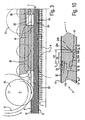
- the machine 2 has an air bed 7 and belts, more particularly upper belts 8.
- the air bed 7 presses the panels 2, which are lying upside down, with their lower side 9 against the driven upper belts 8, which carry the panels 1 along by means of friction.
- the panels 1, by means of shoes or supports 10 are maintained on a well-defined level, whereas the panels 1 are directed with their decorative side 11. downward.
- the represented panels 1 consist of laminate material of the "DPL" type, however, as explained in the introduction, it is clear that the invention is not restricted to the manufacture of panels 1 consisting of such material.
- the represented laminate material comprises a core 12, a decor layer 13, as well as a so-called overlay 14, whereby the decor layer 13 and overlay 14 together form the top layer 15 and consist of carrier sheets impregnated with synthetic material, which are pressed upon the core 12 and whereby the decor layer 13 also is provided with a printed decor.
- the core 12 consists, for example, of a wood-based material, such as MDF or HDF.
- the panels 1 are provided with a backing layer 16, which consists of a carrier sheet soaked in resin.
- Figure 2 shows that the profiled edge regions 5A-5B to be formed of the floor panels 1 comprise coupling parts 17A-17B, more particularly in the form of a tongue 18 and a groove 19.
- the tongue 19 is bordered by means of a lower lip 20 and upper lip 21, whereby in the example, the lower lip 20 to be formed extends beyond the upper lip 21.
- the represented coupling parts 17A-17B in a horizontal as well as in a vertical direction, result in a mutual locking of the respective floor panels 1.
- a guiding groove 22 is formed at the lower side 9 and, as will become clear from the further described figures, profiled edge regions 5A-5B are formed, in such a manner that one of the profiled edge regions, in this case, the edge region 5A, extends such that this region, seen in a cross-section of the floor panels 1, transverse to the guiding groove 22, in other words, seen in the plane of figure 2 , extends at the lower side 2 of each respective floor panel 1 at least up to the guiding groove 22.
- the guiding groove 22 will extend over the entire length of a longitudinal side 3A of the floor panels 1.
- the guiding groove 22 is applied at a narrow side 4A or 4B of such rectangular floor panel 1, or at a longitudinal as well as at a narrow side.
- Figure 2 also shows how the guiding groove 22 can be provided by means of a saw treatment 23. In this case, this saw treatment 23 takes place in the processing machine 2 in which the floor panels 1 are provided with their profiled edge regions 5A-5B at their longitudinal sides 3A-3B.
- the guiding groove 22, measured in a horizontal direction, is situated at such a distance from the vertical plane V, in which the coupled floor panels 1 adjoin each other with their upper sides 24, that one or both of the following criteria are met:
- the guiding groove 22 is realized such that it has a width B between 1 and 4 mm, and still better between 1 and 2 mm, and shows a depth D of 1 to 4 mm, and still better 1.5 to 2.5 mm.
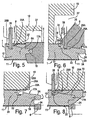
- Forming of the aforementioned profiled edge regions 5A-5B and coupling parts 17A-17B in this case takes place by means of mechanical tools 6, such as milling cutters.
- mechanical tools 6, such as milling cutters As represented in figures 3 to 5 , herein the panels 1 are moved with the guiding groove 22 over guiding portions 26, in this case in the form of a guiding knife, with the purpose of guiding the panels 1 during the formation of at least a portion of the profiled edge regions 5A-5B.
- Figure 4 shows that by means of a rough milling cutter 6 part of the top layer 15 and of the core 12 is removed.
- Figure 15 shows how the tongue 18 substantially is formed. This figure shows that in some cases it is necessary to provide a recess 27 in a shoe 10, such that the respective mechanical tool 6 can rotate freely.
- the panels 1 are moved over at least two guiding portions 26, which together form the guiding knife, between which, at least over the height of the guiding groove 22, a gap 28 is present.
- the gap 28 allows for that, as represented in figure 6 , one of the aforementioned cutting tools 6 can be placed in this gap in order to perform a milling treatment up to the guiding groove 22.
- the represented milling treatment relates to the forming of the lower side of the tongue 18.
- This milling treatment forms, amongst others, a locking part 29A at the panels 1 that allows that two of the finally realized floor panels 1, in coupled condition, are locked in horizontal direction.
- a portion of the actual coupling parts 17A is formed, as simultaneously a material portion is removed that extends up to at least the location where the guiding groove 22 is formed.
- Figure 7 shows the finishing treatment that forms the upper edge 24 of the panel 1.
- the guiding portions 26 herein are no longer active at the height of the location where this finishing treatment takes place, however, it is clear that according to a variant such guiding portion 26 might also be continued up to that point.
- Figure 8 shows a variant of a method according to the first aspect of the present invention.
- the aforementioned finishing treatment takes place after a rough-machining treatment, such as the one of figure 4 .
- treatments may follow as those described in respect to figures 5 and 6 .
- the particularity of this embodiment is that also at the height of the finishing treatment, the guiding portion 26 is situated in the guiding groove 22, which enables a precise edge treatment.
- the guiding portion 26 is situated in the guiding groove 22, which enables a precise edge treatment.
- the precision is particularly important in this finishing treatment, as this determines the final dimensions of the floor panels 1.
- the aforementioned shoes 10 preferably are moveable independently from the guiding portions 26 and that more preferably the guiding portions 26 are fixedly connected to a frame of the processing machine or continuous machine 2.
- Figure 9 represents two floor panels 1 in a coupled condition, which are manufactured by means of a method according to the invention.
- the guiding groove 22 and the profiled edge regions 5A-5B are performed such that the guiding groove 22, in a coupled condition of two of such floor panels 1, is at least partially covered by a material portion 30.
- the aforementioned material portion 30 is formed by a portion of the lower lip 20 of the groove 19.
- the profiled edge regions 5A-5B of the floor panels 1 from the example of figure 9 comprise coupling parts 17A-17B, which are performed with locking parts 29A-29B that engage behind each other and in this manner perform a locking in horizontal direction.
- the locking part 29B is situated in a portion of the lower lip 20 that extends beyond the upper lip 21.
- the aforementioned material portion 30 that partially covers the guiding groove 22, is situated in the portion of the lower lip 20 that extends beyond the upper lip 21.
- the respective locking part 29B is partially situated in the guiding groove 22, or at least in a space 31 that originally formed part of the guiding groove 22.
- Figure 10 shows a variant, wherein, in the represented coupled condition, the guiding groove 22 is largely covered by a material portion 30, in this case a material portion 30 that is situated in the lower lip 20.
- the represented floor panels are also provided with a bevelled edge 32 at their upper side 24, which bevelled edge is obtained by removing a material portion at the respective upper side 24 and the subsequent covering thereof with a decorative layer 33.
- Figure 11 shows a floor panel 1 that is obtained according to a variant of of the invention.
- the guiding groove 22 comprises two substantially parallel sides, flanks or flank portions 25A-25B, which are not vertical.
- one of these flanks 25A forms a locking part 29A at the edge of the floor panel 1 where the tongue 18 is realized.
- This locking part 29A cooperates with the locking part 29B, which is situated in the lower lip 20, and herein has a contact surface 34 that coincides with one of said flanks 29A.
- the represented floor panels comprise a guiding groove 22 with two substantially parallel and substantially vertical flanks 25A-25B, where one of these flanks 25A also forms a locking part 29A at the edge of the floor panel 1 where the tongue 18 is realized.
- Figure 13 represents a floor panel 1 that is obtained according to a variant that does not form part of the present invention.
- the profiled edge region 5B which extends at the lower side 9 of the panel 1 at least up to the guiding groove 22, is realized at the side 3B-4B of the panel 1 at which the groove 19 is formed.
- this method is particularly advantageous where a certain flexibility is expected from the lower lip 20, as this is the case, for example, with some so-called "snap-on connections", wherein during connecting two of such floor panels 1 a bending of this lower lip 20 is required.
- this method can promote or even determine this required flexibility of the lower lip 20 in thicker, for example, solid wooden floor panels 1.
- the guiding groove 22 is provided at such a distance from the upper edge 24 of the floor panels 1, that it is situated at least partially, and still better entirely, in that portion of the lower lip 20 that extends below the upper lip 21.
- Figure 14 represents two more floor panels 1 in a coupled condition, which are obtained, invention by applying a method according to the invention.
- the respective floor panels 1 comprise coupling parts 17A-17B, which are performed substantially in the form of a tongue 18 and a groove 19. In this case, the upper lip 21 and the lower lip 20 that limit the groove 19 are almost equally long.
- a variant of the invention consists in that, when realizing the panels, at least two guiding grooves are employed, which preferably are utilized alternate, more particularly successively.
- the advantage is created that a better guiding can be provided, as, when one of the guiding grooves can not be utilized or is no longer available, then a guiding by means of the other guiding groove can be provided.
- These guiding grooves may be situated both at lower side of the panel, but may also be present at the upper side, lower side, respectively, of such panel.
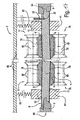
- FIGS 15 and 16 represent a method showing, amongst others, the characteristics of the aforementioned first particular embodiment of the invention.
- panels 1 are transported through a processing machine or continuous machine 2 by means of a first mechanical carrier element 77 and a second mechanical carrier element 78.
- both mechanical elements 77-78 at the height of these contact surfaces 74, are freely movable in a direction transverse to the respective flat panel side 9-11 and can both carrier elements 77-78 adapt themselves in the aforementioned direction to the location of each floor panel 1. So, for example, does the mobility of both carrier elements in the arrangement of the example allow that also the, seen in transfer direction, second floor panel 1 that adopts another location at the height of the carrier elements, can be transported smoothly, as the carrier elements adapt themselves in such a manner that the contacts 79 still can be formed.
- the respective panel 1 has a bending K, as a result of which it takes another location at the height of the carrier elements 77-78.
- this panel 1 by applying a method according to said first particular embodiment, without a problem still can be provided with profiled edge regions 5A-5B.
- the mobility of the mechanical carrier elements 77 and 78, namely, is such that they allow to form the contacts 79 with the respective panel sides 9 and 11 over a distance that is larger than the bending K, measured at the height of these contact surfaces 79.
- both mechanical elements 77-78 comprise belts 8, which, by means of travel wheels 80, are pressed into the direction of said flat panel sides 9 and 11. It is clear that such pressing-on can be realized in various manners. So, for example, may the travel wheels 80 be performed as pressing rollers that are borne in elements, wherein a spring system provides for that these elements, with the pressing rollers borne therein, are pressed against the respective side of the elements 77-78.
- the panels 1, as is evident from figure 17 are provided with a guiding groove 22, that the panels 1 are guided by means of a guiding portion 26 that engages in this guiding groove 26 and that, while the panels 1 are transported through the processing machine 2, they are pressed, in the immediate proximity of their edge regions 5A-5B to be profiled, onto a sliding shoe 81.
- the two pressure shoes 10 can be moved independently from the guiding portion 26.
- the guiding portion 26 is fixedly installed in respect to the frame 83 of the processing machine 2.
- the method according to the present invention does not exclude that, when forming the aforementioned profiled edge regions 5A-5B, use is made of a processing machine, of which the aforementioned first mechanical element 77 comprises a belt 8 and the second mechanical element 78 comprises a conveyor chain 84.
- a processing machine of which the aforementioned first mechanical element 77 comprises a belt 8 and the second mechanical element 78 comprises a conveyor chain 84.
- such conveyor chain 84 consists of links 85 that are connected to each other by means of hinges 86.
- the chain is reversed over minimum 2 return wheels 87 and, over a part of its path, is transported along a guiding element 88.
- the guiding element 88 supports the chain over its entire length.
- a fixedly installed guiding portion 26 is employed. This offers particular advantages when realizing profiled edge regions 5A-5B. Employing a fixedly installed guiding portion 26 in fact minimizes the influence of possible vibrations of the chain onto the panel 1 or generally offers a more stable transport and/or processing of the panels 1.
- the method comprises at least the following steps:
- the processing machine 2 shall preferably also be provided with additional means that minimize the risk of possible vibrations in the chain and/or enhance the stability of the transport or the treatments. Such vibrations or instabilities, namely, may lead to an inferior processing quality.
- the technique where the conveyor chain 84 is pressed upon the guiding element 88 by means of an attraction force the risk of vibrations occurring due to upsetting of the conveyor chain 84 is minimized.
- attraction force can be realized in any manner by creating magnetic attraction forces or pressing forces between, on the one hand, certain parts of the conveyor chain 84, and, on the other hand, certain parts of the guiding element 88.
- the magnetic attraction takes place at guiding elements 88, or portions thereof that are situated at locations where the conveyor chain 84 runs onto the return wheels 87, leave these, respectively. It is, however, clear that the attraction can also be realized at other locations, for example, at the location of the guide 89 and/or at the location of the circumference of the return wheels 87.
- the second technique when employing the second technique, in other words, the technique where the polygon effect in the conveyor chain 84 is minimized, also the occurrence of vibrations in the conveyor chain 84 is minimized.
- the polygon effect occurs there, where the conveyor chain 84 is reversed over the return wheels 87.
- the conveyor chain 84 bends irregularly when reversing. This irregular reversion results in speed variations of the conveyor chain 84 and vibrations that can continue into other parts of the processing machine 2.
- Compensating polygon effects in a conveyor chain is a technique that is known as such, in which respect reference is made to EP 1 304 302 , however, the combination of this technique with the other techniques of the thirteenth aspect as such is novel and inventive.
- the guiding portion 26 is fixedly installed, more particularly rigidly connected to a frame 83 of the processing machine. This arrangement allows a very stable transport of the panels 1 and a correspondingly high quality of the treatments in the machine 2.
- the application of the aforementioned second technique namely, the application of means in order to minimize the polygon effect
- the aforementioned first technique namely, employing a conveyor chain 84, which, by magnetic attraction, is retained on a guiding element 88.
- the aforementioned guiding element 88, over which the conveyor chain 84 is running is provided with a portion that subjects the conveyor chain 84 to a gradual transition movement towards and/or from the return wheel 87, such that the mutual bending of the links 85 during reversing of the conveyor chain 84 occurs more gradually.
Abstract
Description
- The invention relates to a method for manufacturing floor panels.
- In general, the invention relates to hard floor panels, which, at two or more sides, are provided with coupling parts and which can be provided on an existing subfloor, either floatingly.or glued, or in any other manner, in order to form a floor covering. Hereby, the invention is intended in particular for laminate panels, for example, with a printed decor and a top structure on the basis of synthetic material, prefabricated parquet, with panels mostly consisting of several layers of material with, at the upper side, a top layer of solid wood with a thickness of several millimeters, veneer parquet consisting of panels having a layer of veneer at their upper side, or solid parquet. This does not exclude that the invention is also applied for other hard floor panels, whether or not composed of several parts, for example, with top layers of other materials, such as, amongst others, cork, stone or stone-like materials, linoleum, carpet, and so on.
- The invention relates to a method for manufacturing floor panels, which, as aforementioned, are provided with coupling parts at least at two opposite sides.
- It is known that such coupling parts can be formed by means of a classical tongue and groove connection, wherein these, when installing the floor panels, possibly are glued into each other, or by means of mechanical coupling parts providing for a mutual locking of the floor panels in horizontal as well as in vertical directions, for example, as described in the international patent application
WO 97/47834 - It is also known, for example, from the patent document
WO 2004/037502 , when using a continuous machine, to provide a guiding groove approximately in the middle of the lower side of flat panels by means of a saw treatment and to move the panels with this guiding groove over a guiding portion, while providing two opposite sides of the panels with profiled edge regions that comprise coupling parts. Applying this technique guarantees the parallelism of the two respective opposite sides, however, the presence of the guiding groove in the center of the panels may lead to undesired effects, such as, for example, the local weakening of the panels, the heightened risk of moisture penetration and/or warping and the like. The described continuous machine relates to a machine in which the panels are transported by means of an air bed and belts. Hereby, the air bed presses the panels upward against two belts, which, by means of friction, carry the panels along and convey them through the machine. - With such transport, considerably higher passage speeds can be achieved than with traditional chain conveyance systems.
- From
DE 20 2004 018 661 U , which forms the basis for the preamble ofclaim 1, a method for manufacturing floor panels is known, wherein the panels, at their lower side, are provided with a guiding groove and these panels, at least at two opposite sides are provided with coupling parts, in the form of a tongue and a groove, the latter being limited by means of a lower and an upper lip. The guiding groove is provided along one of the longitudinal sides of the panels which are to be profiled close to the area to be profiled. -
WO 2005/068747 , which is a document falling under Art. 54(3) EPC and which is not relevant to the question of inventive step, discloses a method for manufacturing floor panels, wherein the panels, at their lower sides, are provided with a guiding groove. The panels at least at two opposite sides are provided with coupling parts that form a so-called locking system allowing two such panels to become mutually locked in a horizontal as well as in a vertical direction. The guiding groove is provided in an edge portion of the panels where some parts of the locking system are formed. - The present invention now relates to a method for manufacturing floor panels that allows to obtain a better and/or cheaper and/or more flexible and/or more reliable finishing of the floor panels.
- To this aim, the invention relates to the method of
claim 1, wherein is started from panels, these panels, at their lower side, are provided with at least one guiding groove and these panels, at least at two opposite sides, are provided with profiled edge regions that comprise coupling parts, with the characteristic that at least one of the aforementioned two profiled edge regions is formed such that this region, seen in a cross-section of the panel, transverse to the guiding groove, extends at the lower side of the panel at least up to the guiding groove. - By "profiled edge region", any treated region is understood that is situated at the respective edge or in the direct proximity of the respective edge of the floor panel. Such profiled edge regions may comprise regions having a specific function, such as, for example, the function of coupling parts, as well as regions without function.
- By the present invention is achieved that the guiding groove is no longer conspicuously present on the lower side of such panels. Also, the absence of these guiding groove outside of the profiled edge regions of a floor panel means the absence of a local weakening, which weakening might lead to a variety of undesired effects, such as, for example, enlarging the risk of warping of floor panels under the influence of heat and/or humidity. It is clear that these effects are of huge importance with thin floor panels, having dimensions between 5 and 15 mm.
- In consideration of the above, it is clear that at the lower side of the floor panels, apart from one or more guiding grooves situated in the edge profile or adjacent thereto, preferably no other guiding grooves are formed, are present, respectively, in the lower side of the floor panels.
- The panels from which is started, may be obtained from a larger board, for example, by means of a saw treatment. Such board consists, for example, of a board-shaped laminate material, in the case of the production of laminate floor panels, or of another material, which then is chosen in function of the floor panels to be manufactured.
- Such board-shaped laminate material comprises at least a core, whether or not composed of several parts, a decor, as well as a top layer on the basis of synthetic material. The top layer mostly consists of a number of carrier sheets, for example, of paper, which are soaked in resin, for example, a melamine resin. In such case, it is common to perform the laminate as so-called "DPL" (Direct Pressure Laminate), wherein the top layer is pressed directly upon the core, or so-called "HPL" (High Pressure Laminate), wherein the top layer as such is obtained by a press treatment, before the top layer as a whole is provided on the core. Also, other possibilities for forming such top layer are possible, for example, by making use of films, applying a substance to be hardened, such as a varnish or the like, or in any other manner. The decor is mostly printed, either directly on the core, with the possible intermediary of a primer, or on one or more of said carrier sheets or on the aforementioned film.
- The core of such laminate material mostly consists of a wood-based material, such as, for example, MDF (Medium Density Fiberboard)·or HDF (High density Fiberboard).
- Laminate material, as described herein above, is mostly provided with a backing layer at the lower side in order to counteract possible deformations under the influence of humidity and/or crimping effects as a result of the press treatment performed in manufacturing. Herein, this backing layer then mostly also consists of a carrier sheet soaked in resin, which is provided against the lower side by means of a press treatment. Such backing layer offers a balance against possible tensile forces that are present in the material, and in this manner can counteract a possible warping of the material.
- Also other materials than laminate material, which can be applied for the present invention, can be provided with a backing layer, which does not necessarily have to consist of a carrier sheet soaked in resin. So, such backing layer may also consist, for example, of wood, for example, when manufacturing the aforesaid prefabricated parquet.
- Providing, according to the invention, a guiding groove at the lower side of a panel, leads to a repeatable positioning during several processing steps of the manufacture of a floor panel. The same guiding groove can in fact be applied during different processing steps; amongst others, it may, however, not necessarily, be applied for guiding the panels during the forming of at least a portion of the profiled edge regions, wherein the panels to this aim are moved with the guiding groove over one or more guiding portions. In this latter case, the parallelism of the profiled edge regions is guaranteed in an optimum manner. Preferably, the guiding groove is at least applied for guiding the panels while providing the aforementioned coupling parts, as a consequence of which a production of uniform coupling parts within narrow tolerance limits can be guaranteed.
- It is noted that providing a guiding groove at the lower side of the panels does not necessarily have to take place after the panels have been brought approximately to their finished dimensions, however, according to the invention, may also take place beforehand, for example, by providing such guiding groove in the lower side of a board, from which several of such panels are formed.
- Further, it is noted that, when performing the aforementioned profiled edge regions, preferably elements, such as pressure shoes, are applied, which press the panels, in the immediate proximity of both opposite edge regions to be profiled, with at least one of their flat panel sides onto elements, such as sliding shoes.
- In a preferred form of embodiment, the aforementioned pressure-exerting elements or pressure shoes are movable independently from the aforementioned guiding portion, whereby preferably the guiding portion is fixedly installed, more particularly, is rigidly connected to a frame of the processing machine. This installation allows a very stable transport of the panels and a correspondingly high quality of the processing in the machine. Moreover, the accuracy of the guiding of the panels is independent of the wear, the positioning and/or the accuracy of the pressing shoes.
- Also in the case that no pressure-exerting elements, as aforementioned, were applied and that the floor panels thus are supported in another suitable manner, the use of a fixedly arranged guiding portion, more particularly a guiding portion that is rigidly connected to the frame of the processing machine, combined with the first aspect of the invention, offers important advantages. By such arrangement of the guiding portion thus a fixed positioning thereof in respect to the applied tools, such as cutting tools, is obtained, which may contribute to narrow production tolerances.
- It is clear that the invention preferably is performed on continuous machines, wherein the panels are transported in a continuous or almost continuous movement along one or more processing stations, for example, processing stations with rotating mechanical cutting tools. Hereby, preferably use is made of continuous machines, wherein the transport, as aforementioned, takes place by means of belts and an air bed, whereby high passage speeds can be achieved, even up to more than 300 m/min. As will become clear from the further introduction and from the description, it is not excluded that the invention is performed on continuous machines, whereby the panels are transported in another manner. Other possibilities are described hereafter.
- In a preferred form of embodiment, the panels are moved over at least two guiding portions, between which, at least at the height of the guiding groove, a gap is present, wherein one or more processing tools and/or auxiliary tools for forming at least a portion of the respective profiled edge region are active in said gap.
- In a preferred form of embodiment, the guiding groove and the profiled edge regions are performed such that the guiding groove, in a coupled condition of two of such floor panels, is covered at least partially, for example, at least halfway, is covered by a material portion. Still better, the guiding groove is covered at least up to three quarters or even entirely, or almost entirely, as a result of which influences from below can be restricted.
- It is noted that according to the first aspect of the invention, it is not excluded that also other guiding grooves are provided at the lower side of the panels, for example, guiding grooves external to the profiled edge regions, although this, as aforementioned, preferably will not be the case.
- When in the method according to the invention, it is started from a panel that is provided with a backing layer, the method has particular advantages, in particular in the case that the guiding groove is performed completely through the thickness of such backing layer. In that the profiled edge region extends at the lower side at least up to the guiding groove, the backing layer, at least for forming this guiding groove, is not interrupted locally, which provides for that the balance between the tensile forces in the backing layer and the tensile forces in the remaining material at least is not interrupted by forming the respective guiding groove, such that the risk of warping is minimized.
- The aforementioned coupling parts are performed with locking parts, such that, in a coupled condition of at least two of said floor panels, a mutual locking is obtained in a horizontal as well as a vertical direction. Herein, the coupling parts are substantially performed in the form of a tongue and a groove that is bordered by means of a lower and an upper lip, wherein then the profiled edge region extending at the lower side of the panel at least up to the guiding groove is performed at that side of the panel at which the aforementioned tongue is formed. In a particular preferred form of embodiment, the guiding groove is situated at the tongue side at such a distance from the vertical plane in which the coupled floor panels adjoin with their upper side against each other, that one or both of the following criteria are met:
- such that the distance, measured in a horizontal direction, between the aforementioned vertical plane and that side of the guiding groove situated closest thereto, is larger than 3 mm;
- such that the distance, measured in a horizontal direction, between said vertical plane and the side of the guiding groove that is situated the farthest from it is smaller than 12 mm.
- This form of embodiment results in a compact profiled edge portion, whereas still a good and/or sturdy connection of two floor panels is guaranteed. Herein, the aforementioned material portion that at least partially covers the guiding groove, can be formed by a portion of the lower lip. Preferably, the lower lip has a portion that extends beyond the upper lip, and the aforementioned locking parts comprise portions that engage behind each other and in this manner effect a locking in horizontal direction, wherein one of these locking parts is situated in the portion of the lower lip that extends beyond the upper lip, and the aforementioned material portion also is situated in the portion of the lower lip that extends beyond the upper lip.
- Herein, the aforementioned locking part that is situated at the lower lip, in the coupled condition of two of such floor panels, preferably is situated at least partially in the guiding groove, or at least in a space originally forming part of the guiding groove. Such configuration minimizes the risk of dust and moisture penetrating into the connection system.
- In general, it is preferred that, after forming the profiled edge regions, at least a remainder of the aforementioned guiding groove remains present, in other words, at least two lateral flank portions of this guiding groove are maintained, such that the remainder of the guiding groove still can be applied, for example, for other treatments, or for further conveyance of the floor panels.
- It is clear that according to the invention, the guiding groove is particularly useful when manufacturing the floor panels, and that such guiding groove does not necessarily have to remain present at floor panels. that are obtained by the application of a method according to the invention. Thus, the fact that such profiled edge region according to the invention is performed at least up to the guiding groove, does not exclude that such edge region is performed up to entirely beyond the guiding groove and, as a result hereof, the guiding groove is completely removed from the final floor panel.
- In general, it is noted that in applications where the floor panels have a backing layer, it is preferred that this backing layer is uninterrupted over the entire lower side of the floor panels, in other words, outside of the profiled edge regions.
- It is noted that, when forming the aforementioned profiled edge regions and the guiding groove adjoining thereto and, thus, pertaining thereto, preferably mechanical cutting tools are applied, such as milling cutters, saws, planes or the like. Further, it is noted that the.guiding groove is not necessarily provided in the same machine where also the actual profiled edge regions are formed, but can also be provided separately.
- It is noted that according to the first aspect of the invention, the guiding groove can be applied before, during as well as after forming the actual profiled edge regions, thus, the portion of the edge regions exclusive of the guiding groove.
- In a preferred form of embodiment, when forming the coupling parts, and in particular when forming a locking part providing for a locking in horizontal direction, with the same tool a portion of the actual coupling parts is formed, as well as simultaneously a material portion, which extends up to at least the location where the guiding groove is formed or shall be formed, is removed. In this form of embodiment, it is not necessary to remove additional material portions and/or to apply additional cutting tools in order to obtain that the respective edge region extends up to the guiding groove.
- A method according to the invention can also be applied for manufacturing floor panels, where the aforementioned profiled edge regions at the upper edge of the floor panels are provided with a surface that is obtained by removing a material portion, for example, in the form of a bevelled edge. Examples of such floor panels with a bevelled edge are known, amongst others, from the
WO 01/96688 - According to a deviating variant which does not form part of the invention, the panels are provided with a guiding groove at their upper side instead of at their lower side, wherein at least one of the aforementioned two profiled edge regions is formed such that this region, seen in a cross-section of the panel, transverse to the guiding groove, extends at the upper side of the panel at least up to the guiding groove. In such case, it is preferred that the guiding groove is performed at the groove side of the panel, wherein a longer lower lip is formed at the groove, and the guiding groove is performed in the projecting longer portion of the lower lip and/or is performed in the material portion that originally is situated above the projecting longer portion of the lower lip.
- It is noted that, according to the invention, the guiding groove can be provided in any manner. So, for example, it may be formed by the application of a machining operation, such as sawing, milling, planing or the like. According to an alternative embodiment, the guiding groove consists of an impression that is applied, for example, by means of a press treatment. This alternative form of embodiment entrains a broad range of advantages. So, for example, it becomes possible to obtain a guiding groove in the lower side of the panels without interrupting a possible backing layer, such that the above-mentioned disadvantages of interrupting the backing layer do not occur.
- The present invention does not exclude that the panels from which is started may also consist of other than the aforementioned materials, such as synthetic materials. Amongst others according to its first and second aspect, the invention also does not exclude that the panels from which is started are obtained in another manner than from a larger board, for example, by extrusion.
- According to the invention floor panels can be obtained which, at least at two opposite sides, are provided with profiled edge regions, which comprise at least coupling parts, which consist at least of a tongue and a groove, with which, in the coupled condition of two of such panels, a locking in vertical direction is obtained, as well as locking parts, which, in a coupled condition of two of such panels, effect a locking in horizontal direction, wherein these locking parts have contact surfaces effecting at least the aforementioned locking in horizontal direction, wherein, at the lower side of the floor panel, close to the side of the floor panel that is provided with the aforementioned tongue, a groove with, at opposite sides, two substantially parallel and substantially vertical flanks is present, wherein this groove integrally forms part of the respective profiled edge region and wherein these flanks and said contact surfaces consist of different surfaces. It is clear that by "different surfaces" is meant that said vertical flanks and said contact surfaces are not situated in each other's prolongation. However, it is noted that said contact surfaces do not necessarily have to be flat. They may have any shape, such as, for example, a bent shape.
- The aforementioned two flanks at opposite sides of the groove are extremely well suited for receiving a guiding element and, thus, for serving as a guiding groove when transporting such floor panels before, during or after their manufacture.
- Moreover, the groove of the floor panels can be performed such that in respect to positioning in respect to other parts of the floor panel the same properties are obtained as described in respect to the guiding groove of the invention. The particularity herein is that, for example, the groove, in the coupled condition of two floor panels, is at least partially covered by a portion of the aforementioned lower lip.
- According to a first particular embodiment, the invention , offers an enhanced stability when performing profiled edge regions at opposite sides of a panel.
- Herein, the method of the first particular embodiment is of the type that comprises at least the following steps:
- transporting the panels through a processing machine by means of at least a first mechanical carrier element and a second mechanical carrier element, wherein the panels, at their opposite first flat panel side and second flat panel side, come into contact with a respective carrier element and wherein at least the first mechanical carrier element, at least of the height of the respective contact with the flat panel side, is freely movable in a direction transverse to the respective flat panel side;
- performing profiled edge regions at least at two opposite sides of the panels, while the panels, as aforementioned, are transported through the processing machine and herein are moved, with their edge regions to be profiled, along cutting tools.
- It is clear that by "flat panel sides" generally the two largest surfaces of the panels are meant, or, in other words, the surfaces that, in the normal use of the floor panel, form the lower side and the upper side or the decorative side, respectively. In this context, the term "plane" is used only for indicating the upper side and lower side and does not mean that these sides must have a completely flat shape. It is noted that it is also not excluded that the aforementioned flat panel sides have impressions or other unevennesses.
- A method of said type is known, for example, from
DE 200 20 505 U1 . InDE 200 20 505 Ul, on the one hand, a belt supported by travel wheels is applied as a first movable carrier element, and, on the other hand, a conveyor chain fixedly installed in a direction of the respective flat panel side is used as a second carrier element. Herein, the travel wheels press the belt in the aforementioned direction against the respective flat panel side, such that the opposite flat panel side comes into contact with the fixedly installed conveyor chain. In other words, the first carrier element adapts in the aforementioned direction to the location of each respective floor panel. Methods, wherein a fixedly installed element is applied as the second mechanical carrier element, however, show reduced grip, when the panels show a certain curvature in length and/or in transverse direction. In those cases, the contact between the second carrier element and the respective panel side is lost, because the first, movable carrier element is no longer capable of pressing the panels onto the fixedly installed second carrier element. For this reason, the panels may be "stuck" in the processing machine, which leads to low quality treatments and a hindrance to production. The loss of contact with one of the carrier elements and/or the temporarily being stuck or slipping of the panels results in an increased risk of scratches and/or reduced gloss of the upper side or decorative side of the panels. - According to said first particular embodiment the second mechanical carrier element also, at least at the height of the respective contact with the flat panel side, is freely movable in a direction transverse to the respective flat panel side, more particularly such that both carrier elements adapt themselves according to the aforementioned direction to the location of each respective floor panel at the height of the aforesaid carrier elements.
- The mobility of the mechanical carrier elements at the height of said contact can be obtained in any manner.
- So, for example, may one or both of the applied carrier elements, according to a first possibility, have a certain freedom of movement in a direction transverse to the plane of the panels.
- According to a second possibility, one or both of the applied carrier elements, at the height of said contact, may consist of a compressible material. It is clear that the invention also relates to a method in which both possibilities are combined.
- However the aforementioned mobility may have been obtained, in a preferred form of embodiment mechanical carrier elements are applied, which, at least at the height of the contact with the floor panels, are freely movable in the aforementioned direction over a distance of at least 0.3 millimeters, and still better at least 0.6 millimeters.
- It is noted that, for realizing contacts over these distances, in each case when they are in the order of magnitude of 1 mm or larger, other elements must be applied than elements that comprise an air guiding. An air guiding in fact always maintains a constant small gap between its bed and the object to be transported; this is either the panel itself, or a belt, which then is in contact with the panel. Although it is not excluded that an air guiding, such as mentioned above in the introduction, may also have specific advantages, it is generally advantageous to avoid the application of an air guiding, if possible, as the air consumption may form a considerable portion of the cost price of such method.
- A method according to said first particular embodiment of the invention can preferably be realized with a first and second mechanical carrier element, which both are formed by a belt that, by means of travel wheels, then is pressed against the respective flat panel side. A method, in which only one mechanical carrier element is applied that comprises such positively supported belt, as such is known from the above-mentioned
WO 2004/037502 , however, the present invention, according to a preferred form of embodiment, relates to a method, where the aforementioned first as well as the aforementioned second mechanical carrier element is performed in such manner. - In comparison with a method in which a conveyor chain is applied as the second mechanical carrier element, the use of belts has the additional advantage that the so-called "polygon effect" will not occur. The polygon effect occurs at conveyor chains, there, where the chain is reversed over a so-called return wheel. As a result of the length of its links, the chain bends irregularly when reversing. This irregular reversion results in speed variations of the chain and the panels transported thereby. These speed variations in their turn may lead to an inferior processing quality. However, it is not excluded that one or both of the aforementioned mechanical carrier elements, according to the sixth aspect of the invention, may also be performed as a chain that is at least movable at the height of said contact with the flat panel side.
- In a preferred form of embodiment, the method also comprises the step of guiding the panels by means of a guiding portion that engages in said guiding groove, while the panels, as aforementioned, are transported through the processing machine.
- It is noted that, when performing the aforementioned profiled edge regions, preferably pressure-exerting elements, such as pressure shoes, are applied, which press the panels in the immediate proximity of both opposite edge areas to be profiled with at least one of their flat panel sides onto a counter element, such as a sliding shoe.
- In a preferred form of embodiment, the aforementioned pressure-exerting elements are movable independently from said guiding portion, or even better is said guiding portion fixedly installed, or is more particularly rigidly connected to a frame of the processing machine. This arrangement allows a very stable transport of the panels and a correspondingly high quality of the treatments in the machine.
- A method, which, applies a first and a second mechanical carrier element for transporting the panels through a processing machine, wherein both carrier elements are formed by positively supporting belts, as such is of particular importance. Such method is in fact cheaper and more simple than a method, in which the panels are transported between a belt and a conveyor chain, or between a belt and an air bed, whereas such method still allows to obtain an accurate processing. Therefore, the method of the invention, according to a second particular embodiment , comprises at least the following steps:
- transporting the panels through a processing machine by means of at least a first and a second mechanical carrier element, which respectively cooperate with opposite first and second flat panel sides;
- providing profiled edge regions at least at two opposite sides of the panels, while the panels, as aforementioned, are transported through the processing machine and therein, with their edge regions to be profiled, are moved along cutting tools;
- Such mechanical support of the belts may be obtained, for example, by applying belts, which are pressed, by means of travel wheels, in the direction of the aforementioned flat panel sides.
- In a preferred form of said second particular embodiment the method also comprises the step of guiding the panels by means of a guiding portion that engages in said guiding groove, while they, as aforementioned, are transported through the processing machine.
- Preferably, the aforementioned panels, in the immediate proximity of both opposite edge regions to be profiled, are pressed by means of a pressure-exerting element, such as a pressure shoe, with at least one of their flat panel sides onto a counter element, such as a sliding shoe.
- In a preferred form of embodiment, the aforementioned pressure-exerting elements can be moved independently from the aforesaid guiding portion, or, still better, said guiding portion is fixedly installed and more particularly is rigidly connected to a frame of the processing machine. This arrangement allows a very stable transport of the panels and a correspondingly high quality of the treatments in the machine.
- With the intention of better showing the characteristics of the invention, hereafter, as an example without any limitative character, several preferred forms of embodiment are described, with reference to the accompanying drawings, wherein:
-
Figure 1 schematically represents a method according to the invention; -
figure 2 represents a cross-section according to the line II-II infigure 1 ; -
figure 3 represents a cross-section according to the line III-III infigure 2 ; -
figures 4 to 7 represent cross-sections according to the lines IV-IV, V-V, VI-VI, VII-VII infigure 1 ; -
figure 8 represents a variant of the invention; -
figures 9 to 12 represent floor panels, which have been obtained by means of a method according to the invention; -
figure 13 represents a floor panel that is obtained according to a variant not comprised in the invention; -
figure 14 represents floor panels obtained by a method with the characteristics of an embodiment of the present invention; -
figures 15 to 17 represent a method with the characteristics of the invention, wherefigure 16 and17 represent cross-sections according to line XLVI-XLVI infigure 15 and line XLVII-XLVII infigure 16 , respectively; -
figures 18 and19 represent a method with the characteristics of, the invention, wherebyfigure 19 represents a cross-section according to line XLIX-XLIX infigure 18 . -
Figure 1 schematically shows howfloor panels 1 can be obtained by means of a method according to the present invention. In the represented example, this relates torectangular floor panels 1, which, by means of two processing machines, more particularlycontinuous machines 2, are provided with profilededge regions 5A-5B at theirlongitudinal sides 3A-3B as well as at their transverse or short sides 4A-4B. Herein, the so-called "continuous milling" is applied. First, thepanels 1 are moved with theirlongitudinal sides 3A-3B over themechanical cutting tools 6. Then their short or transverse sides 4A-4B are subjected to similar treatments. - It is noted that the term "panels" substantially is applied as long as the floor panels have not entirely been provided with profiled edge regions, whereas the term "floor panels" is applied when these profiled edge regions indeed have been provided. In both cases, however, the
reference number 1 is applied thereto. -
Figures 2 and3 represent howsuch panels 1 can be transported through thefirst processing machine 2. To this aim, themachine 2 has an air bed 7 and belts, more particularlyupper belts 8. The air bed 7 presses thepanels 2, which are lying upside down, with theirlower side 9 against the drivenupper belts 8, which carry thepanels 1 along by means of friction. At the height of their edges, thepanels 1, by means of shoes or supports 10, are maintained on a well-defined level, whereas thepanels 1 are directed with theirdecorative side 11. downward. - The represented
panels 1 consist of laminate material of the "DPL" type, however, as explained in the introduction, it is clear that the invention is not restricted to the manufacture ofpanels 1 consisting of such material. - The represented laminate material comprises a core 12, a
decor layer 13, as well as a so-calledoverlay 14, whereby thedecor layer 13 andoverlay 14 together form thetop layer 15 and consist of carrier sheets impregnated with synthetic material, which are pressed upon thecore 12 and whereby thedecor layer 13 also is provided with a printed decor. Thecore 12 consists, for example, of a wood-based material, such as MDF or HDF. At theirlower side 9, which here, when the profilededge regions 5A-5B are formed, is oriented upward, thepanels 1 are provided with abacking layer 16, which consists of a carrier sheet soaked in resin. -
Figure 2 shows that the profilededge regions 5A-5B to be formed of thefloor panels 1 comprisecoupling parts 17A-17B, more particularly in the form of atongue 18 and agroove 19. Herein, thetongue 19 is bordered by means of alower lip 20 andupper lip 21, whereby in the example, thelower lip 20 to be formed extends beyond theupper lip 21. In a coupled condition of at least two of theaforementioned floor panels 1, the representedcoupling parts 17A-17B, in a horizontal as well as in a vertical direction, result in a mutual locking of therespective floor panels 1. - As can be seen in
figure 2 , according to the invention a guidinggroove 22 is formed at thelower side 9 and, as will become clear from the further described figures, profilededge regions 5A-5B are formed, in such a manner that one of the profiled edge regions, in this case, theedge region 5A, extends such that this region, seen in a cross-section of thefloor panels 1, transverse to the guidinggroove 22, in other words, seen in the plane offigure 2 , extends at thelower side 2 of eachrespective floor panel 1 at least up to the guidinggroove 22. - Preferably, as represented in
figure 3 , when the method according to the first aspect is applied for manufacturingrectangular floor panels 1, the guidinggroove 22 will extend over the entire length of alongitudinal side 3A of thefloor panels 1. Within the scope of the invention, it is also possible that the guidinggroove 22 is applied at anarrow side 4A or 4B of suchrectangular floor panel 1, or at a longitudinal as well as at a narrow side. - In the example of
figure 2 , the profilededge region 5A that extends at thelower side 9 of thefloor panels 1 at least up to the guidinggroove 22, is performed at that side at which theaforementioned tongue 18 is formed.Figure 2 also shows how the guidinggroove 22 can be provided by means of asaw treatment 23. In this case, this sawtreatment 23 takes place in theprocessing machine 2 in which thefloor panels 1 are provided with their profilededge regions 5A-5B at theirlongitudinal sides 3A-3B. - Preferably, the guiding
groove 22, measured in a horizontal direction, is situated at such a distance from the vertical plane V, in which the coupledfloor panels 1 adjoin each other with theirupper sides 24, that one or both of the following criteria are met: - such that the distance D1 between the aforementioned vertical plane V and the
side 25A of the guidinggroove 22 situated closest thereto, is larger than 3 mm; - such that the distance D2 between said vertical plane V and the
side 25B of the guidinggroove 22 that is situated the farthest from it is smaller than 12 mm. - Further, it is preferred that the guiding
groove 22 is realized such that it has a width B between 1 and 4 mm, and still better between 1 and 2 mm, and shows a depth D of 1 to 4 mm, and still better 1.5 to 2.5 mm. - Forming of the aforementioned profiled
edge regions 5A-5B andcoupling parts 17A-17B in this case takes place by means ofmechanical tools 6, such as milling cutters. As represented infigures 3 to 5 , herein thepanels 1 are moved with the guidinggroove 22 over guidingportions 26, in this case in the form of a guiding knife, with the purpose of guiding thepanels 1 during the formation of at least a portion of the profilededge regions 5A-5B.Figure 4 shows that by means of arough milling cutter 6 part of thetop layer 15 and of thecore 12 is removed.Figure 15 shows how thetongue 18 substantially is formed. This figure shows that in some cases it is necessary to provide arecess 27 in ashoe 10, such that the respectivemechanical tool 6 can rotate freely. - As represented in
figure 3 , thepanels 1 are moved over at least two guidingportions 26, which together form the guiding knife, between which, at least over the height of the guidinggroove 22, agap 28 is present. - The
gap 28 allows for that, as represented infigure 6 , one of theaforementioned cutting tools 6 can be placed in this gap in order to perform a milling treatment up to the guidinggroove 22. The represented milling treatment relates to the forming of the lower side of thetongue 18. This milling treatment forms, amongst others, a lockingpart 29A at thepanels 1 that allows that two of the finally realizedfloor panels 1, in coupled condition, are locked in horizontal direction. Infigure 6 , with one and thesame cutting tool 6 as well a portion of theactual coupling parts 17A is formed, as simultaneously a material portion is removed that extends up to at least the location where the guidinggroove 22 is formed. -
Figure 7 shows the finishing treatment that forms theupper edge 24 of thepanel 1. In the represented example, the guidingportions 26 herein are no longer active at the height of the location where this finishing treatment takes place, however, it is clear that according to a variant such guidingportion 26 might also be continued up to that point. - It is noted that, as becomes quite clear from
figures 6 and 7 , after forming the profilededge regions 5A-5B, at least a remainder of the guidinggroove 22 remains present, in other words, at least two lateral flank portions of thesides 25A-25B of this guidinggroove 22 are maintained at thelower side 9 of thefloor panels 1, such that they can be applied for further processing. -
Figure 8 shows a variant of a method according to the first aspect of the present invention. Herein, the aforementioned finishing treatment takes place after a rough-machining treatment, such as the one offigure 4 . Thereafter, treatments may follow as those described in respect tofigures 5 and 6 . The particularity of this embodiment is that also at the height of the finishing treatment, the guidingportion 26 is situated in the guidinggroove 22, which enables a precise edge treatment. In this manner, by means of ashoe 10, it is also possible to give a better support to the edge regions of thefloor panels 1 at the height of the treatment. The precision is particularly important in this finishing treatment, as this determines the final dimensions of thefloor panels 1. - Generally, it is noted that the
aforementioned shoes 10 preferably are moveable independently from the guidingportions 26 and that more preferably the guidingportions 26 are fixedly connected to a frame of the processing machine orcontinuous machine 2. -
Figure 9 represents twofloor panels 1 in a coupled condition, which are manufactured by means of a method according to the invention. Hereby, the guidinggroove 22 and the profilededge regions 5A-5B are performed such that the guidinggroove 22, in a coupled condition of two ofsuch floor panels 1, is at least partially covered by amaterial portion 30. In this example, theaforementioned material portion 30 is formed by a portion of thelower lip 20 of thegroove 19. - The profiled
edge regions 5A-5B of thefloor panels 1 from the example offigure 9 comprisecoupling parts 17A-17B, which are performed with lockingparts 29A-29B that engage behind each other and in this manner perform a locking in horizontal direction. The lockingpart 29B is situated in a portion of thelower lip 20 that extends beyond theupper lip 21. Also theaforementioned material portion 30 that partially covers the guidinggroove 22, is situated in the portion of thelower lip 20 that extends beyond theupper lip 21. In the coupled condition, therespective locking part 29B is partially situated in the guidinggroove 22, or at least in aspace 31 that originally formed part of the guidinggroove 22. -
Figure 10 shows a variant, wherein, in the represented coupled condition, the guidinggroove 22 is largely covered by amaterial portion 30, in this case amaterial portion 30 that is situated in thelower lip 20. The represented floor panels are also provided with a bevelled edge 32 at theirupper side 24, which bevelled edge is obtained by removing a material portion at the respectiveupper side 24 and the subsequent covering thereof with adecorative layer 33. -
Figure 11 shows afloor panel 1 that is obtained according to a variant of of the invention. Herein, the guidinggroove 22 comprises two substantially parallel sides, flanks orflank portions 25A-25B, which are not vertical. Herein, one of theseflanks 25A forms a lockingpart 29A at the edge of thefloor panel 1 where thetongue 18 is realized. This lockingpart 29A cooperates with the lockingpart 29B, which is situated in thelower lip 20, and herein has acontact surface 34 that coincides with one of saidflanks 29A. - In
figure 12 , the represented floor panels comprise a guidinggroove 22 with two substantially parallel and substantiallyvertical flanks 25A-25B, where one of theseflanks 25A also forms a lockingpart 29A at the edge of thefloor panel 1 where thetongue 18 is realized. Thecontact surface 34 that is formed when cooperating with the lockingpart 29B, which is situated in thelower lip 20, coincides with one of saidflanks 25A. -
Figure 13 represents afloor panel 1 that is obtained according to a variant that does not form part of the present invention. Herein, the profilededge region 5B, which extends at thelower side 9 of thepanel 1 at least up to the guidinggroove 22, is realized at theside 3B-4B of thepanel 1 at which thegroove 19 is formed. It is noted that this method is particularly advantageous where a certain flexibility is expected from thelower lip 20, as this is the case, for example, with some so-called "snap-on connections", wherein during connecting two of such floor panels 1 a bending of thislower lip 20 is required. Thus, this method can promote or even determine this required flexibility of thelower lip 20 in thicker, for example, solidwooden floor panels 1. In particular, the guidinggroove 22 is provided at such a distance from theupper edge 24 of thefloor panels 1, that it is situated at least partially, and still better entirely, in that portion of thelower lip 20 that extends below theupper lip 21. -
Figure 14 represents twomore floor panels 1 in a coupled condition, which are obtained, invention by applying a method according to the invention. Therespective floor panels 1 comprisecoupling parts 17A-17B, which are performed substantially in the form of atongue 18 and agroove 19. In this case, theupper lip 21 and thelower lip 20 that limit thegroove 19 are almost equally long. - A variant of the invention consists in that, when realizing the panels, at least two guiding grooves are employed, which preferably are utilized alternate, more particularly successively. Hereby, the advantage is created that a better guiding can be provided, as, when one of the guiding grooves can not be utilized or is no longer available, then a guiding by means of the other guiding groove can be provided. These guiding grooves may be situated both at lower side of the panel, but may also be present at the upper side, lower side, respectively, of such panel.
-
Figures 15 and 16 represent a method showing, amongst others, the characteristics of the aforementioned first particular embodiment of the invention. Herein,panels 1 are transported through a processing machine orcontinuous machine 2 by means of a firstmechanical carrier element 77 and a secondmechanical carrier element 78. Herein, thepanels 1, at their opposite flat panel sides, thus, at the panel side formed by thedecorative side 11, as well as at thelower side 9, come into contact with an carrier element, 77-78, respectively. This contact is indicated byreference 79. - As becomes clear from
figures 15 and 16 , both mechanical elements 77-78, at the height of these contact surfaces 74, are freely movable in a direction transverse to the respective flat panel side 9-11 and can both carrier elements 77-78 adapt themselves in the aforementioned direction to the location of eachfloor panel 1. So, for example, does the mobility of both carrier elements in the arrangement of the example allow that also the, seen in transfer direction,second floor panel 1 that adopts another location at the height of the carrier elements, can be transported smoothly, as the carrier elements adapt themselves in such a manner that thecontacts 79 still can be formed. - As becomes clear from
figure 17 , therespective panel 1 has a bending K, as a result of which it takes another location at the height of the carrier elements 77-78. As aforementioned thispanel 1, by applying a method according to said first particular embodiment, without a problem still can be provided with profilededge regions 5A-5B. The mobility of themechanical carrier elements contacts 79 with therespective panel sides - In the present case, the aforementioned mobility is obtained in that both mechanical elements 77-78
comprise belts 8, which, by means oftravel wheels 80, are pressed into the direction of saidflat panel sides travel wheels 80 be performed as pressing rollers that are borne in elements, wherein a spring system provides for that these elements, with the pressing rollers borne therein, are pressed against the respective side of the elements 77-78. - From
figures 15 to 17 , it becomes clear that the illustrated method also shows the characteristics of the aforementioned second particular embodiment of the invention. - It is noted that the
panels 1, as is evident fromfigure 17 , are provided with a guidinggroove 22, that thepanels 1 are guided by means of a guidingportion 26 that engages in this guidinggroove 26 and that, while thepanels 1 are transported through theprocessing machine 2, they are pressed, in the immediate proximity of theiredge regions 5A-5B to be profiled, onto a slidingshoe 81. As schematically represented with thesprings 82, the twopressure shoes 10 can be moved independently from the guidingportion 26. Moreover, the guidingportion 26 is fixedly installed in respect to theframe 83 of theprocessing machine 2. - With reference to
figure 18 , it is further noted that the method according to the present invention does not exclude that, when forming the aforementioned profilededge regions 5A-5B, use is made of a processing machine, of which the aforementioned firstmechanical element 77 comprises abelt 8 and the secondmechanical element 78 comprises aconveyor chain 84. As represented,such conveyor chain 84 consists oflinks 85 that are connected to each other by means of hinges 86. The chain is reversed overminimum 2return wheels 87 and, over a part of its path, is transported along a guidingelement 88. As represented by the dashedline 89, it is not excluded that the guidingelement 88 supports the chain over its entire length. - In combination with the
conveyor chain 84, as represented infigure 19 , also a fixedly installed guidingportion 26 is employed. This offers particular advantages when realizing profilededge regions 5A-5B. Employing a fixedly installed guidingportion 26 in fact minimizes the influence of possible vibrations of the chain onto thepanel 1 or generally offers a more stable transport and/or processing of thepanels 1. - According to a third particular embodiment, the method comprises at least the following steps:
- transporting
panels 1 through aprocessing machine 2 by means of at least onecarrier element 78 that consists of aconveyor chain 84; - realizing profiled
edge portions 5A-5B at least at twoopposite sides 3A-3B, 4A-4B of thepanels 1, while thepanels 1, by means of theaforementioned conveyor chain 84, are transported through theaforementioned processing machine 2 and therein are moved with theiredge regions 5A-5B to be profiled alongcutting tools 6; - guiding the
panels 1 by means of a guidingportion 26, which engages in a guidinggroove 22 provided in thepanels 1 to this aim, while the panels, as aforementioned, are transported through theprocessing machine 2; - In the case that at least one
mechanical carrier element 78 is realized as a conveyor chain, theprocessing machine 2 shall preferably also be provided with additional means that minimize the risk of possible vibrations in the chain and/or enhance the stability of the transport or the treatments. Such vibrations or instabilities, namely, may lead to an inferior processing quality. - According to a fourth particular embodiment the method comprises at least the following steps:
- transporting
panels 1 through aprocessing machine 2 by means of at least one carrier element 77-78 that consists of aconveyor chain 84 formed bylinks 85; - realizing profiled
edge portions 5A-5B at least at twoopposite sides 3A-3B and/or 4A-4B of thepanels 1, while thepanels 1, by means of theaforementioned conveyor chain 84, are transported through theaforementioned processing machine 2 and therein are moved with theiredge regions 5A-5B to be profiled alongcutting tools 6; - the technique where the
conveyor chain 84, at least over a portion of its path, is transported along a guidingelement 88 and is pressed by means of magnetic forces against the guidingelement 88; - the technique where means are applied for minimizing the polygon effect of the
conveyor chain 84; - the technique where the
panels 1 are laterally guided by means of a guidingportion 26 that engages in a guidinggroove 22 provided in the panels, while they, as aforementioned, are transported through theprocessing machine 2. - It is clear that the invention also relates to the three possible combinations of two of the above techniques, as well as the combination of all above techniques.
- When employing the first technique, in other words, the technique where the
conveyor chain 84 is pressed upon the guidingelement 88 by means of an attraction force, the risk of vibrations occurring due to upsetting of theconveyor chain 84 is minimized. It is clear that such attraction force can be realized in any manner by creating magnetic attraction forces or pressing forces between, on the one hand, certain parts of theconveyor chain 84, and, on the other hand, certain parts of the guidingelement 88. In view of the fact that such magnetic systems for attracting conveyor chains against their guide are known as such, this will not be further discussed in detail. Preferably, the magnetic attraction takes place at guidingelements 88, or portions thereof that are situated at locations where theconveyor chain 84 runs onto thereturn wheels 87, leave these, respectively. It is, however, clear that the attraction can also be realized at other locations, for example, at the location of theguide 89 and/or at the location of the circumference of thereturn wheels 87. - When employing the second technique, in other words, the technique where the polygon effect in the
conveyor chain 84 is minimized, also the occurrence of vibrations in theconveyor chain 84 is minimized. As aforementioned, the polygon effect occurs there, where theconveyor chain 84 is reversed over thereturn wheels 87. As a consequence of its link length, theconveyor chain 84 bends irregularly when reversing. This irregular reversion results in speed variations of theconveyor chain 84 and vibrations that can continue into other parts of theprocessing machine 2. - The aforementioned means for minimizing the polygon effect can consist of one or preferably a combination of at least two of the following precautions:
- the aforementioned guiding
element 88, along which the conveyor chain is transported at least over a part of its path, is provided with a portion that subjects theconveyor chain 84 to a gradual transition movement towards and/or from thereturn wheel 87, such that the mutual bending of thelinks 85 during reversion of theconveyor chain 84 occurs more gradually, wherein the length of this transition movement preferably is shorter than two link lengths; - the portion mentioned in the preceding paragraph that subjects the
conveyor chain 84 to a gradual transition movement, is installed such that an arriving chain portion, previous to the transition movement, is supplied in a straight line by means of a theoretical path, the prolongation of which is situated outward of the pitch circle of the pertainingreturn wheel 87; - the
conveyor chain 84 compriseslinks 85 with a maximum link length of 100 millimeter; - the
return wheel 87 is such that minimum tenlinks 85 can be situated thereupon; - the pitch circle of the
return wheel 87 has a minimum radius of one and a half times the link length, and best is larger than two times the link length. - Compensating polygon effects in a conveyor chain is a technique that is known as such, in which respect reference is made to
EP 1 304 302 - When employing the third technique, namely, guiding the
panels 1 by means of a guidingportion 26 that engages in said guidinggroove 22, it is achieved that thepanels 1 are positively guided during their transport through theprocessing machine 2. In a preferred form of embodiment, the guidingportion 26 is fixedly installed, more particularly rigidly connected to aframe 83 of the processing machine. This arrangement allows a very stable transport of thepanels 1 and a correspondingly high quality of the treatments in themachine 2. - It is clear that combining the aforementioned stabilizing means can offer various synergetic effects.
- It is, for example, clear that the application of the aforementioned second technique, namely, the application of means in order to minimize the polygon effect, preferably is combined with the aforementioned first technique, namely, employing a
conveyor chain 84, which, by magnetic attraction, is retained on a guidingelement 88. This is quite clear, when the aforementioned guidingelement 88, over which theconveyor chain 84 is running, is provided with a portion that subjects theconveyor chain 84 to a gradual transition movement towards and/or from thereturn wheel 87, such that the mutual bending of thelinks 85 during reversing of theconveyor chain 84 occurs more gradually. - It becomes also clear from the fourth particular embodiment that combining the first technique with the third technique may have many advantages for the stability of the transport and/or the quality of the processing of the
panels 1. - When combining the second and the third technique, also an improvement of the stability of the transport and/or the quality of the processing of the
panels 1 is obtained. Preferably, however, as aforementioned, all three aforementioned techniques are applied in combination, such that the risk of the occurrence of vibrations of which kind whatsoever is minimized.
Claims (14)
- Method for manufacturing floor panels, wherein is started from panels (1), these panels (1), at their lower side (9), are provided with at least one guiding groove (22) and these panels (1), at least at two opposite sides (3A-3B;4A-4B), are provided with profiled edge regions (5A-5B) that comprise coupling parts (17A-17B), substantially in the form of a tongue (18) and a groove (19), the latter being limited by means of a lower lip (20) and an upper lip (21), characterized in that the aforementioned coupling parts (17A-17B) are performed with locking parts (29A-29B), such that, in a coupled condition of at least two of said floor panels (1), a mutual locking is obtained in a horizontal as well as in a vertical direction, wherein said floor panels have a thickness between 5 and 15 millimeter, and at least one of the aforementioned two profiled edge regions (5A-5B) is formed such that this region, seen in a cross-section of the panel (1), transverse to the guiding groove (22), extends at the lower side (9) of the panel (1) at least up to the guiding groove (22) and wherein said guiding groove (22) is performed at that side (3A-4A) of the panel (1) at which the aforementioned tongue (18) is formed.
- Method according to claim 1, characterized in that the guiding groove (22) and the profiled edge regions (5A-5B) are performed such that the guiding groove (22), in a coupled condition of two of such floor panels (1), is covered at least partially by a material portion (30).
- Method according to claim 2, characterized in that the aforementioned material portion (30) that covers the guiding groove (22) at least partially is formed by a portion of the lower lip (20).
- Method according to claim 2 or 3, characterized in that the aforementioned lower lip (20) has a portion that extends beyond the upper lip (21); that said locking parts (29A-29B) comprise portions that engage behind each other and in this manner effect a locking in horizontal direction; that one of these locking parts (29B) is situated in the portion of the lower lip (20) that extends beyond the upper lip (21); and that the aforementioned material portion (30) is also situated in the portion of the lower lip (20) that extends beyond the upper lip (21).
- Method according to claim 4, characterized in that the aforementioned locking part (29B) that is situated at the lower lip (20), in coupled condition of two of such floor panels (1), is situated at least partially in the guiding groove (22), or at least in a space (31) that originally formed part of the guiding groove (22).
- Method according to any of the preceding claims, characterized in that the aforementioned guiding groove (22) is applied at least for guiding the panels (1) at least during forming at least a portion of the profiled edge regions (5A-5B), wherein the panels (1) to this aim are moved with the guiding groove (22) over one or more guiding portions (26).
- Method according to claim 6, characterized in that the panels (1) are moved over at least two guiding portions (26), between which, at least over the height of the guiding groove (22), a gap (28) is present, wherein one or more processing tools (6) and/or auxiliary tools (10) for forming at least a portion of the respective profiled edge region (5A-5B) are active in said gap (28).
- Method according to claim 6 or 7, characterized in that the aforementioned guiding groove (22) is applied at least for guiding the panels (1) during the realization of the aforementioned coupling parts (17A-17B).
- Method according to any of the preceding claims, characterized in that the guiding groove (22), measured in a horizontal direction, is situated at such a distance from the vertical plane (V) in which the coupled floor panels (1) adjoin with their upper side (24) against each other, that one or both of the following criteria are met:- such that the distance (D1) between the aforementioned vertical plane (V) and the closest-situated side (25A) of the guiding groove (22) is larger than 3 mm;- such that the distance (D2) between said vertical plane (V) and the side (25B) of the guiding groove (22) that is situated the farthest from it is smaller than 12 mm.
- Method according to any of the preceding claims, characterized in that, after forming the profiled edge regions (5A-5B), at least a remainder of the aforementioned guiding groove (22) remains present, in other words, at least two lateral flank portions (25A-25B) of this guiding groove (22) are maintained.
- Method according to any of the preceding claims, characterized in that, when forming the coupling parts (17A-17B), and more particularly when forming a locking part (29A) providing for a locking in horizontal direction, by means of the same tool (6) a portion of the actual coupling parts (17A) is formed, as well as simultaneously a material portion is removed that extends up to at least the location where the guiding groove (22) is formed or is to be formed.
- Method according to any of the preceding claims, characterized in that the panels (1) are transported through a processing machine (2) by means of at least one carrier element (78) that consists of a conveyor chain (84), that said profiled edge portions (5A-5B) are realized while the panels (1), by means of the aforementioned conveyor chain (84), are transported through the aforementioned processing machine (2) and therein are moved with their edge regions (5A-5B) to be profiled along cutting tools (6), that the panels (1) are laterally guided by means of a guiding portion (26), which engages in said guiding groove (22), while the panels, as aforementioned, are transported through the processing machine (2).
- Method according to claim 12, characterized in that the guiding portion (26) is fixedly installed, more particularly is rigidly connected to a frame (83) of the processing machine (2).
- Method according to claim 12 or 13, characterized in that said conveyor chain (84) is formed by links and that at least one of the following techniques is employed:- the technique where the conveyor chain (84), at least over a portion of its path, is transported along a guiding element (88) and is pressed by means of magnetic forces against the guiding element (88);- the technique where means are applied for minimizing the polygon effect of the conveyor chain (84).
Priority Applications (4)
| Application Number | Priority Date | Filing Date | Title |
|---|---|---|---|
| EP10075493A EP2298516A3 (en) | 2005-03-31 | 2006-03-28 | Method for manufacturing floor panels, as well as floor panel |
| EP09075312A EP2108492B1 (en) | 2005-03-31 | 2006-03-28 | Methods for manufacturing floor panels |
| EP08075858A EP2030746A1 (en) | 2005-03-31 | 2006-03-28 | Methods for manufacturing and packaging floor panels, devices used thereby, as well as floor panel and packed set of floor panels |
| PL06727536T PL1890853T3 (en) | 2005-03-31 | 2006-03-28 | Method for manufacturing floor panels |
Applications Claiming Priority (4)
| Application Number | Priority Date | Filing Date | Title |
|---|---|---|---|
| BE2005/0169A BE1016561A6 (en) | 2005-03-31 | 2005-03-31 | Floor panel manufacturing method, involves providing panels at lower side with guiding groove and providing two opposite sides with profiled edge regions that comprise coupling parts |
| US67253805P | 2005-04-19 | 2005-04-19 | |
| BE2006/0024A BE1016938A6 (en) | 2005-03-31 | 2006-01-12 | Floor panel manufacturing method, involves providing panels at lower side with guiding groove and providing two opposite sides with profiled edge regions that comprise coupling parts |
| PCT/IB2006/000993 WO2006103565A2 (en) | 2005-03-31 | 2006-03-28 | Methods for manufacturing and packaging floor panels, devices used thereby, as well as floor panel and packed set of floor panels. |
Related Child Applications (1)
| Application Number | Title | Priority Date | Filing Date |
|---|---|---|---|
| EP08075858A Division EP2030746A1 (en) | 2005-03-31 | 2006-03-28 | Methods for manufacturing and packaging floor panels, devices used thereby, as well as floor panel and packed set of floor panels |
Publications (2)
| Publication Number | Publication Date |
|---|---|
| EP1890853A2 EP1890853A2 (en) | 2008-02-27 |
| EP1890853B1 true EP1890853B1 (en) | 2009-01-21 |
Family
ID=38543904
Family Applications (4)
| Application Number | Title | Priority Date | Filing Date |
|---|---|---|---|
| EP06727536A Active EP1890853B1 (en) | 2005-03-31 | 2006-03-28 | Method for manufacturing floor panels |
| EP08075858A Withdrawn EP2030746A1 (en) | 2005-03-31 | 2006-03-28 | Methods for manufacturing and packaging floor panels, devices used thereby, as well as floor panel and packed set of floor panels |
| EP09075312A Active EP2108492B1 (en) | 2005-03-31 | 2006-03-28 | Methods for manufacturing floor panels |
| EP10075493A Withdrawn EP2298516A3 (en) | 2005-03-31 | 2006-03-28 | Method for manufacturing floor panels, as well as floor panel |
Family Applications After (3)
| Application Number | Title | Priority Date | Filing Date |
|---|---|---|---|
| EP08075858A Withdrawn EP2030746A1 (en) | 2005-03-31 | 2006-03-28 | Methods for manufacturing and packaging floor panels, devices used thereby, as well as floor panel and packed set of floor panels |
| EP09075312A Active EP2108492B1 (en) | 2005-03-31 | 2006-03-28 | Methods for manufacturing floor panels |
| EP10075493A Withdrawn EP2298516A3 (en) | 2005-03-31 | 2006-03-28 | Method for manufacturing floor panels, as well as floor panel |
Country Status (8)
| Country | Link |
|---|---|
| US (4) | US8161701B2 (en) |
| EP (4) | EP1890853B1 (en) |
| AT (2) | ATE490068T1 (en) |
| BE (1) | BE1016938A6 (en) |
| DE (2) | DE602006004992D1 (en) |
| ES (1) | ES2321445T3 (en) |
| PL (1) | PL1890853T3 (en) |
| WO (1) | WO2006103565A2 (en) |
Cited By (1)
| Publication number | Priority date | Publication date | Assignee | Title |
|---|---|---|---|---|
| RU2470794C2 (en) * | 2009-12-23 | 2012-12-27 | Флоринг Текнолоджиз Лтд. | Method and device for refining particle board |
Families Citing this family (63)
| Publication number | Priority date | Publication date | Assignee | Title |
|---|---|---|---|---|
| SE517478C2 (en) * | 1999-04-30 | 2002-06-11 | Valinge Aluminium Ab | Locking system for mechanical hoisting of floorboards, floorboard provided with the locking system and method for producing mechanically foldable floorboards |
| BE1016938A6 (en) * | 2005-03-31 | 2007-10-02 | Flooring Ind Ltd | Floor panel manufacturing method, involves providing panels at lower side with guiding groove and providing two opposite sides with profiled edge regions that comprise coupling parts |
| US20130139478A1 (en) | 2005-03-31 | 2013-06-06 | Flooring Industries Limited, Sarl | Methods for packaging floor panels, as well as packed set of floor panels |
| BE1016846A3 (en) | 2005-11-09 | 2007-08-07 | Flooring Ind Ltd | Floor covering has hard floor panels having at least one chamfer having surface covered with separate decorative covering by transfer printing technique |
| US7971327B2 (en) | 2006-03-10 | 2011-07-05 | Mannington Mills, Inc. | Process and system for sub-dividing a laminated flooring substrate |
| BE1017157A3 (en) | 2006-06-02 | 2008-03-04 | Flooring Ind Ltd | FLOOR COVERING, FLOOR ELEMENT AND METHOD FOR MANUFACTURING FLOOR ELEMENTS. |
| DE102007035235A1 (en) | 2007-07-27 | 2009-01-29 | Wemhöner Anlagen GmbH & Co. KG | Laminar body processing machine for use in e.g. building industry, has guide groove formed in rear side of work piece, where guidance of work piece in horizontal and vertical directions is ensured via slide strip from downward |
| US8353140B2 (en) * | 2007-11-07 | 2013-01-15 | Valinge Innovation Ab | Mechanical locking of floor panels with vertical snap folding |
| EP2163362A1 (en) * | 2008-09-15 | 2010-03-17 | Spanolux N.V. Div. Balterio | A method and apparatus for manufacturing a short panel piece |
| NL2003699A (en) | 2008-12-18 | 2010-06-21 | Brion Tech Inc | Method and system for lithography process-window-maximixing optical proximity correction. |
| CA2750731C (en) * | 2009-01-30 | 2017-09-26 | Rene St-Cyr (1996) Inc. | Manufacturing of tongue and groove profiles on hardwood floorboards |
| US11717901B2 (en) | 2009-07-31 | 2023-08-08 | Valinge Innovation Ab | Methods and arrangements relating to edge machining of building panels |
| CN102574292B (en) | 2009-07-31 | 2016-05-18 | 瓦林格创新股份有限公司 | Process relevant method and apparatus to the edge of building panelling |
| EP3750676B1 (en) | 2009-07-31 | 2023-04-26 | Välinge Innovation AB | Tool configuration relating to edge machining of building panels |
| DK2339092T3 (en) | 2009-12-22 | 2019-07-22 | Flooring Ind Ltd Sarl | Method of Manufacturing Coating Panels |
| DE102010019567A1 (en) | 2010-05-05 | 2011-11-10 | Fritz Egger Gmbh & Co. Og | Panel, in particular floor panel with chamfered edges and method for the production of such panels |
| BE1019331A5 (en) | 2010-05-10 | 2012-06-05 | Flooring Ind Ltd Sarl | FLOOR PANEL AND METHODS FOR MANUFACTURING FLOOR PANELS. |
| US8925275B2 (en) | 2010-05-10 | 2015-01-06 | Flooring Industries Limited, Sarl | Floor panel |
| BE1019501A5 (en) | 2010-05-10 | 2012-08-07 | Flooring Ind Ltd Sarl | FLOOR PANEL AND METHOD FOR MANUFACTURING FLOOR PANELS. |
| US9695600B2 (en) * | 2011-10-03 | 2017-07-04 | Unilin Bvba | Panel and method for manufacturing panels |
| ES2484698T3 (en) * | 2011-10-31 | 2014-08-12 | Tetra Laval Holdings & Finance S.A. | Folding unit to produce folded containers of pourable food products from corresponding sealed containers |
| BE1020305A5 (en) * | 2011-12-05 | 2013-07-02 | Unilin Bvba | PACKED SET OF PANELS. |
| PL3238899T3 (en) | 2012-06-19 | 2020-12-28 | Välinge Innovation AB | Mechanical locking system for floorboards |
| US20140102590A1 (en) * | 2012-10-16 | 2014-04-17 | Michael Towey | Monocoque furniture assembly and method of manufacture |
| BE1021497B1 (en) * | 2012-11-20 | 2015-12-03 | Unilin Bvba | PACKED SET OF PANELS |
| US9835189B2 (en) * | 2014-05-28 | 2017-12-05 | The Boeing Company | Sandwich panel joints and methods for joining sandwich panels |
| DE102014116781A1 (en) * | 2014-10-10 | 2016-04-14 | Hamberger Industriewerke Gmbh | Double end |
| DE102015005864A1 (en) * | 2015-05-11 | 2016-11-17 | Fritz Egger Gmbh & Co. Og | Process for the production of wells having panels |
| DE102015008891B3 (en) * | 2015-07-09 | 2016-08-25 | Ima Klessmann Gmbh Holzbearbeitungssysteme | Method and device for edge thickness measurement when applying edge lamination on the narrow sides of plate-shaped workpieces |
| DE102016001995A1 (en) | 2016-02-19 | 2017-08-24 | Siempelkamp Logistics & Service GmbH | Device and method for trimming and measuring a plate |
| EP3309323A1 (en) * | 2016-10-11 | 2018-04-18 | Franz Eschlbeck | Panel and panel connection |
| BE1024723B1 (en) * | 2016-11-10 | 2018-06-11 | Ivc Bvba | Floor panel and method for manufacturing a floor panel. |
| DE102017002271A1 (en) | 2017-03-09 | 2018-09-13 | Ima Klessmann Gmbh Holzbearbeitungssysteme | Method for dividing a plate-shaped workpiece |
| DE102017106329A1 (en) | 2017-03-23 | 2018-09-27 | Guido Schulte | Processing plant for plate-shaped workpieces |
| USD945870S1 (en) | 2020-11-17 | 2022-03-15 | National Nail Corp. | Fastener positioning device |
| US11149445B2 (en) | 2017-08-15 | 2021-10-19 | National Nail Corp. | Hidden fastener unit and related method of use |
| US11111679B2 (en) | 2017-08-15 | 2021-09-07 | National Nail Corp. | Hidden fastener unit and related method of use |
| USD850897S1 (en) | 2018-05-18 | 2019-06-11 | National Nail Corp. | Fastener positioning device |
| US20210277668A1 (en) | 2017-08-15 | 2021-09-09 | National Nail Corp. | Hidden fastener unit and related method of use |
| USD853829S1 (en) | 2018-06-01 | 2019-07-16 | National Nail Corp. | Fastener positioning device |
| US10378218B2 (en) | 2017-08-15 | 2019-08-13 | National Nail Corp. | Hidden fastener unit and related method of use |
| USD1019365S1 (en) | 2023-05-31 | 2024-03-26 | National Nail Corp. | Fastener positioning device |
| US11261893B2 (en) | 2017-08-15 | 2022-03-01 | National Nail Corp. | Hidden fastener unit and related method of use |
| USD924044S1 (en) | 2019-11-20 | 2021-07-06 | National Nail Corp. | Fastener positioning device |
| US11898357B2 (en) | 2017-08-15 | 2024-02-13 | National Nail Corp. | Hidden fastener unit and related method of use |
| WO2019139519A1 (en) | 2018-01-10 | 2019-07-18 | Välinge Innovation AB | Subfloor joint |
| BE1026099B1 (en) * | 2018-03-16 | 2019-10-14 | Kreafin Group Sa | PANEL OF WHICH THE COUPLING DEVICES ARE SUITABLE FOR CONNECTING THE LONG SIDE AND / OR KOPSE SIDE TOGETHER |
| WO2020117117A1 (en) | 2018-12-05 | 2020-06-11 | Välinge Innovation AB | Subfloor joint |
| USD850898S1 (en) | 2019-01-07 | 2019-06-11 | National Nail Corp. | Fastener positioning device |
| BE1027083B1 (en) | 2019-02-26 | 2020-09-24 | Flooring Ind Ltd Sarl | Sliding or pressure shoe for a continuous milling machine and method for manufacturing panels |
| WO2020180237A1 (en) | 2019-03-05 | 2020-09-10 | Ceraloc Innovation Ab | Methods for forming grooves in a board element and an associated panel |
| CN109968432B (en) * | 2019-03-28 | 2023-05-26 | 豪德机械(上海)有限公司 | Floor back slotting equipment |
| CN109794978B (en) * | 2019-03-28 | 2023-05-26 | 豪德机械(上海)有限公司 | Floor back slotting equipment with dust collection treatment function |
| DE202019101807U1 (en) | 2019-03-29 | 2019-05-06 | Akzenta Paneele + Profile Gmbh | paneling |
| EP3798385A1 (en) | 2019-09-24 | 2021-03-31 | Välinge Innovation AB | Building panel |
| US20210114250A1 (en) * | 2019-10-18 | 2021-04-22 | Jeff Chandler | Method and apparatus for reducing loss due to chipout |
| BE1027883B1 (en) | 2019-12-18 | 2021-07-27 | Unilin Bv | Method for manufacturing panels |
| BE1028185B1 (en) | 2020-04-03 | 2021-11-04 | Flooring Ind Ltd Sarl | Panel |
| US11731252B2 (en) | 2021-01-29 | 2023-08-22 | National Nail Corp. | Screw guide and related method of use |
| NO20220456A1 (en) * | 2022-04-22 | 2023-10-23 | Beaulieu Int Group Nv | Method for manufacturing a wood-topped covering panel with a bevelled edge |
| BE1030681B1 (en) | 2022-07-01 | 2024-01-29 | Flooring Ind Ltd Sarl | Set of milling tools and method for manufacturing panels |
| WO2024013623A1 (en) | 2022-07-14 | 2024-01-18 | Flooring Industries Limited, Sarl | Method for manufacturing panels and panels obtained thereby |
| USD1022684S1 (en) | 2023-02-23 | 2024-04-16 | National Nail Corp. | Fastener positioning device |
Citations (2)
| Publication number | Priority date | Publication date | Assignee | Title |
|---|---|---|---|---|
| DE202004018661U1 (en) * | 2004-11-13 | 2005-02-17 | Torwegge Holzbearbeitungsmaschinen Gmbh | Double end tenoner with workpiece guide rail |
| WO2005068747A1 (en) * | 2004-01-13 | 2005-07-28 | Välinge Innovation AB | Floor covering and locking system and an equipement for production of e.g floorboards. |
Family Cites Families (274)
| Publication number | Priority date | Publication date | Assignee | Title |
|---|---|---|---|---|
| US2732706A (en) | 1956-01-31 | Friedman | ||
| US1194636A (en) | 1916-08-15 | Silent door latch | ||
| US124228A (en) | 1872-03-05 | Improvement in skate-fastenings | ||
| US753791A (en) | 1903-08-25 | 1904-03-01 | Elisha J Fulghum | Method of making floor-boards. |
| US1331018A (en) | 1919-09-29 | 1920-02-17 | Joseph O Luthy | Separator for secondary batteries |
| SE57493C1 (en) | 1923-10-01 | 1924-09-16 | ||
| US1723306A (en) | 1927-08-02 | 1929-08-06 | Harry E Sipe | Resilient attaching strip |
| US1743492A (en) | 1927-08-02 | 1930-01-14 | Harry E Sipe | Resilient plug, dowel, and coupling pin |
| US1809393A (en) | 1929-05-09 | 1931-06-09 | Byrd C Rockwell | Inlay floor construction |
| US1802514A (en) * | 1929-06-10 | 1931-04-28 | Arthur B Johnson | Sawing machine |
| US1859667A (en) * | 1930-05-14 | 1932-05-24 | J K Gruner Lumber Company | Jointed lumber |
| US1902716A (en) | 1931-09-08 | 1933-03-21 | Midland Creosoting Company | Flooring |
| US2026511A (en) | 1934-05-14 | 1935-12-31 | Storm George Freeman | Floor and process of laying the same |
| US2184113A (en) | 1935-03-05 | 1939-12-19 | Annunziata Calafati | Building construction |
| US2204675A (en) | 1937-09-29 | 1940-06-18 | Frank A Grunert | Flooring |
| US2596280A (en) | 1947-03-21 | 1952-05-13 | Standard Railway Equipment Mfg | Metal covered walls |
| US2666233A (en) | 1949-01-12 | 1954-01-19 | Edwin O Klemm | Prefabricated building construction |
| US2517939A (en) | 1949-05-06 | 1950-08-08 | Stewart James Elliott | Lumber package-rescaled, divisional, bound, and protectively covered |
| US2559261A (en) | 1949-10-17 | 1951-07-03 | Michael D Schwartz | Architectural model construction set |
| US2740167A (en) | 1952-09-05 | 1956-04-03 | John C Rowley | Interlocking parquet block |
| US2863185A (en) | 1954-02-16 | 1958-12-09 | Arnold T Riedi | Joint construction including a fastener for securing two structural members together in edge-to-edge closely abutting relation |
| US2865058A (en) | 1955-04-12 | 1958-12-23 | Gustaf Kahr | Composite floors |
| FR1138595A (en) | 1955-12-15 | 1957-06-17 | Tool for working with wooden heel blanks | |
| US3023681A (en) | 1958-04-21 | 1962-03-06 | Edoco Technical Products | Combined weakened plane joint former and waterstop |
| US3077703A (en) | 1959-04-17 | 1963-02-19 | Wood Conversion Co | Roof deck structure |
| US3177279A (en) | 1961-10-19 | 1965-04-06 | Cavrok Mfg Company | Method of molding a decorative building panel |
| US3350827A (en) | 1964-01-02 | 1967-11-07 | Ridge Rock Ind Inc | Building panels and method of mounting the panels |
| US3271787A (en) | 1964-04-06 | 1966-09-13 | Arthur L Clary | Resilient swimming pool coping |
| US3325585A (en) | 1966-03-15 | 1967-06-13 | John H Brenneman | Combined panel fastener and electrical conduit |
| US3396640A (en) | 1966-04-25 | 1968-08-13 | Grace W R & Co | Joint sealing devices |
| US3378958A (en) | 1966-09-21 | 1968-04-23 | Goodrich Co B F | Extrusions having integral portions of different stiffness |
| US3387422A (en) * | 1966-10-28 | 1968-06-11 | Bright Brooks Lumber Company O | Floor construction |
| GB1171337A (en) | 1967-01-28 | 1969-11-19 | Transitoria Trading Company Ab | A Latching Means for Cupboard Doors, Locker Doors, Drawers and like Openable Members |
| US3512324A (en) | 1968-04-22 | 1970-05-19 | Lola L Reed | Portable sectional floor |
| US3594979A (en) | 1968-07-15 | 1971-07-27 | Abitibi Corp | Automatic board wrapping machine |
| US3517927A (en) | 1968-07-24 | 1970-06-30 | William Kennel | Helical spring bouncing device |
| US3572224A (en) | 1968-10-14 | 1971-03-23 | Kaiser Aluminium Chem Corp | Load supporting plank system |
| US3579941A (en) * | 1968-11-19 | 1971-05-25 | Howard C Tibbals | Wood parquet block flooring unit |
| US3526071A (en) | 1969-02-17 | 1970-09-01 | Kogyo Gomu Co Ltd | Panel for curtain walls and method of jointing corners of the same |
| SE515324C2 (en) | 2000-06-22 | 2001-07-16 | Tarkett Sommer Ab | Floor board with connecting means |
| US3760547A (en) | 1969-08-13 | 1973-09-25 | J Brenneman | Spline and seat connector assemblies |
| US3535844A (en) | 1969-10-30 | 1970-10-27 | Glaros Products Inc | Structural panels |
| US3641730A (en) | 1969-12-19 | 1972-02-15 | Alan F Meckstroth | Expandable joint device |
| DE2108141A1 (en) | 1970-02-20 | 1971-09-30 | Bruun & Soerensen A/S, Aarhus (Dänemark) | Floor construction |
| DE2021503A1 (en) | 1970-05-02 | 1971-11-25 | Freudenberg Carl Fa | Floor panels and methods of joining them |
| DE2111324C3 (en) | 1971-03-10 | 1979-07-05 | Migua-Mitteldeutsche Gummi Und Asbestgesellschaft Hammerschmidt & Co, 5628 Heiligenhaus | Device for sealing joints between components |
| GB1398709A (en) | 1971-07-12 | 1975-06-25 | Bpb Industries Ltd | Building panel |
| DE2159042C3 (en) | 1971-11-29 | 1974-04-18 | Heinrich 6700 Ludwigshafen Hebgen | Insulating board, in particular made of rigid plastic foam |
| US3786608A (en) * | 1972-06-12 | 1974-01-22 | W Boettcher | Flooring sleeper assembly |
| US3778954A (en) | 1972-09-07 | 1973-12-18 | Johns Manville | Method of replacing a damaged bulkhead panel |
| US3835620A (en) | 1973-01-02 | 1974-09-17 | Alcan Aluminum Corp | Apparatus for stacking panels or the like |
| US3919820A (en) | 1973-12-13 | 1975-11-18 | Johns Manville | Wall structure and device for sealing thereof |
| FR2256807A1 (en) | 1974-01-07 | 1975-08-01 | Merzeau Jean Alain | Woodworking tool forming slots - has multiple sets of toothed rotary cutters and spacers altered to vary spacing of slots |
| CA1012731A (en) | 1974-08-30 | 1977-06-28 | Beaconfield Consulting Services Limited | Attaching means for members at an angle to one another |
| AT341738B (en) | 1974-12-24 | 1978-02-27 | Hoesch Werke Ag | CONNECTING ELEMENT WITH SLOT AND SPRING CONNECTION |
| AR207658A1 (en) | 1975-07-15 | 1976-10-22 | Gen Tire & Rubber Co | REINFORCED ELASTOMERIC SEAL AND A METHOD OF MANUFACTURING IT |
| US4080086A (en) | 1975-09-24 | 1978-03-21 | Watson-Bowman Associates, Inc. | Roadway joint-sealing apparatus |
| US3980173A (en) * | 1975-10-02 | 1976-09-14 | Owens-Illinois, Inc. | Precision moving platform |
| US4169688A (en) | 1976-03-15 | 1979-10-02 | Sato Toshio | Artificial skating-rink floor |
| US4064571A (en) | 1976-09-13 | 1977-12-27 | Timerax Holdings Ltd. | Pool liner retainer |
| US4082129A (en) | 1976-10-20 | 1978-04-04 | Morelock Donald L | Method and apparatus for shaping and planing boards |
| US4113399A (en) | 1977-03-02 | 1978-09-12 | Hansen Sr Wray C | Knob spring |
| US4107892A (en) | 1977-07-27 | 1978-08-22 | Butler Manufacturing Company | Wall panel unit |
| ES230786Y (en) | 1977-08-27 | 1978-03-16 | GASKET FOR ROOF PANELS. | |
| DE2828769A1 (en) | 1978-06-30 | 1980-01-03 | Oltmanns Heinrich Fa | BOX-SHAPED BUILDING BOARD MADE OF EXTRUDED PLASTIC |
| SE407174B (en) | 1978-06-30 | 1979-03-19 | Bahco Verktyg Ab | TURNING HAND TOOLS WITH SHAFT HALL ROOM FOR STORAGE OF TOOL ELEMENT |
| EP0013852A1 (en) | 1979-01-25 | 1980-08-06 | Claude Delfolie | Door consisting of slightly elastically deformable plastic profile members |
| US4479333A (en) | 1979-03-05 | 1984-10-30 | Hendrich John H | Folded building module and method of assembly |
| US4426820A (en) | 1979-04-24 | 1984-01-24 | Heinz Terbrack | Panel for a composite surface and a method of assembling same |
| GB2051916A (en) | 1979-05-02 | 1981-01-21 | Ludford D | Structural Panels, Connectors Therefor and a Structure Erected Therefrom |
| US4304083A (en) | 1979-10-23 | 1981-12-08 | H. H. Robertson Company | Anchor element for panel joint |
| US4471012A (en) | 1982-05-19 | 1984-09-11 | Masonite Corporation | Square-edged laminated wood strip or plank materials |
| US4538392A (en) | 1983-02-09 | 1985-09-03 | Horner Flooring Company | Portable sectional flooring system |
| DK149498C (en) | 1983-04-07 | 1986-12-01 | Inter Ikea As | CLOTHING OF BREADS FOR EX. FLOORS OR PANELS |
| US4512131A (en) | 1983-10-03 | 1985-04-23 | Laramore Larry W | Plank-type building system |
| DE3343601A1 (en) | 1983-12-02 | 1985-06-13 | Bütec Gesellschaft für bühnentechnische Einrichtungen mbH, 4010 Hilden | Joining arrangement for rectangular boards |
| US4648165A (en) | 1984-11-09 | 1987-03-10 | Whitehorne Gary R | Metal frame (spring puller) |
| US4819932A (en) | 1986-02-28 | 1989-04-11 | Trotter Jr Phil | Aerobic exercise floor system |
| US5135597A (en) | 1988-06-23 | 1992-08-04 | Weyerhaeuser Company | Process for remanufacturing wood boards |
| US5007222A (en) | 1988-11-14 | 1991-04-16 | Raymond Harry W | Foamed building panel including an internally mounted stud |
| US5071282A (en) | 1988-11-17 | 1991-12-10 | The D. S. Brown Company, Inc. | Highway expansion joint strip seal |
| US5247773A (en) | 1988-11-23 | 1993-09-28 | Weir Richard L | Building structures |
| US5024045A (en) | 1989-03-02 | 1991-06-18 | Certainteed Corporation | Panel packaging system |
| DE3908851A1 (en) * | 1989-03-17 | 1990-09-20 | Peter Schacht | METHOD FOR PRODUCING MULTI-LAYER PANEL BOARDS PREFERRED FOR FLOORS |
| US5148850A (en) | 1989-06-28 | 1992-09-22 | Paneltech Ltd. | Weatherproof continuous hinge connector for articulated vehicular overhead doors |
| DE3923427A1 (en) | 1989-07-15 | 1991-01-24 | Clouth Gummiwerke Ag | BODY SOUND INSULATING MAT |
| DE3932980A1 (en) | 1989-10-03 | 1991-11-28 | Hoelscher & Leuschner Gmbh | Plastic panels for emergency shelters - form walls, floors, roofs with edge grooves having recesses linked by separate barbed PVC connectors |
| US5113632A (en) | 1990-11-07 | 1992-05-19 | Woodline Manufacturing, Inc. | Solid wood paneling system |
| US5348778A (en) | 1991-04-12 | 1994-09-20 | Bayer Aktiengesellschaft | Sandwich elements in the form of slabs, shells and the like |
| US5182892A (en) | 1991-08-15 | 1993-02-02 | Louisiana-Pacific Corporation | Tongue and groove board product |
| JPH05131594A (en) | 1991-11-12 | 1993-05-28 | Kawatetsu Galvanizing Co Ltd | Cloth-covered metal plate |
| US5344700A (en) | 1992-03-27 | 1994-09-06 | Aliquot, Ltd. | Structural panels and joint connector arrangement therefor |
| DE4215273C2 (en) | 1992-05-09 | 1996-01-25 | Dietmar Groeger | Covering for covering floor, wall and / or ceiling surfaces, in particular in the manner of a belt floor |
| US5634309A (en) | 1992-05-14 | 1997-06-03 | Polen; Rodney C. | Portable dance floor |
| US5295341A (en) | 1992-07-10 | 1994-03-22 | Nikken Seattle, Inc. | Snap-together flooring system |
| US5283102A (en) * | 1992-10-28 | 1994-02-01 | Premier Wood Floors | Laminated wood flooring product and wood floor |
| DE4242530C2 (en) | 1992-12-16 | 1996-09-12 | Walter Friedl | Building element for walls, ceilings or roofs of buildings |
| JP2507265B2 (en) | 1993-03-11 | 1996-06-12 | 花王株式会社 | Method and device for transferring articles to container |
| US20020178674A1 (en) | 1993-05-10 | 2002-12-05 | Tony Pervan | System for joining a building board |
| US7121059B2 (en) | 1994-04-29 | 2006-10-17 | Valinge Innovation Ab | System for joining building panels |
| SE9301595L (en) | 1993-05-10 | 1994-10-17 | Tony Pervan | Grout for thin liquid hard floors |
| JPH0748879A (en) | 1993-08-05 | 1995-02-21 | Takeshige Shimonohara | Connecting method and connecting structure for member |
| US5598682A (en) | 1994-03-15 | 1997-02-04 | Haughian Sales Ltd. | Pipe retaining clip and method for installing radiant heat flooring |
| US5465546A (en) | 1994-05-04 | 1995-11-14 | Buse; Dale C. | Portable dance floor |
| SE9500810D0 (en) | 1995-03-07 | 1995-03-07 | Perstorp Flooring Ab | Floor tile |
| US7131242B2 (en) * | 1995-03-07 | 2006-11-07 | Pergo (Europe) Ab | Flooring panel or wall panel and use thereof |
| US6421970B1 (en) | 1995-03-07 | 2002-07-23 | Perstorp Flooring Ab | Flooring panel or wall panel and use thereof |
| US5618602A (en) | 1995-03-22 | 1997-04-08 | Wilsonart Int Inc | Articles with tongue and groove joint and method of making such a joint |
| US5542537A (en) | 1995-07-12 | 1996-08-06 | Riverwood International Corporation | Packaging of rectangular articles |
| US5755068A (en) | 1995-11-17 | 1998-05-26 | Ormiston; Fred I. | Veneer panels and method of making |
| BR7502683U (en) | 1995-11-24 | 1996-04-09 | Jacob Abrahams | Constructive arrangements in joints of strips for laminate floors or ceilings |
| JP3954673B2 (en) | 1996-11-01 | 2007-08-08 | 株式会社ヤマックス | Joint for water stop of concrete joints |
| BE1010487A6 (en) | 1996-06-11 | 1998-10-06 | Unilin Beheer Bv | FLOOR COATING CONSISTING OF HARD FLOOR PANELS AND METHOD FOR MANUFACTURING SUCH FLOOR PANELS. |
| US5950389A (en) | 1996-07-02 | 1999-09-14 | Porter; William H. | Splines for joining panels |
| US6203653B1 (en) | 1996-09-18 | 2001-03-20 | Marc A. Seidner | Method of making engineered mouldings |
| US5694730A (en) | 1996-10-25 | 1997-12-09 | Noranda Inc. | Spline for joining boards |
| EP0874105B1 (en) | 1997-04-22 | 2004-08-04 | Mondo S.p.A. | A layered flooring, in particular for athletic facilities |
| US5862912A (en) | 1997-04-24 | 1999-01-26 | Owens Corning Fiberglas Technology, Inc. | Package of building-panel products |
| AT405560B (en) | 1997-06-18 | 1999-09-27 | Kaindl M | ARRANGEMENT OF COMPONENTS AND COMPONENTS |
| IT237576Y1 (en) | 1997-07-11 | 2000-09-13 | Unifor Spa | PERFECTED CONNECTION SYSTEM BETWEEN MODULAR PANELS |
| DE19747930A1 (en) * | 1997-08-21 | 1999-05-06 | Babcock Bsh Gmbh | Process and plant for the production of wood-based panels |
| US6330980B1 (en) | 1997-11-03 | 2001-12-18 | Joachim Fiedrich | Dry installation of a radiant floor or wall hydronic heating system, metal radiating plates that attach to the edges of side-by-side boards and provide metal slots for holding hot water tubing |
| US6295779B1 (en) | 1997-11-26 | 2001-10-02 | Fred C. Canfield | Composite frame member and method of making the same |
| CO4870729A1 (en) | 1998-02-09 | 1999-12-27 | Steven C Meyerson | CONSTRUCTION PANELS |
| US6272437B1 (en) * | 1998-04-17 | 2001-08-07 | Cae Inc. | Method and apparatus for improved inspection and classification of attributes of a workpiece |
| US6173548B1 (en) | 1998-05-20 | 2001-01-16 | Douglas J. Hamar | Portable multi-section activity floor and method of manufacture and installation |
| SE512290C2 (en) | 1998-06-03 | 2000-02-28 | Valinge Aluminium Ab | Locking system for mechanical joining of floorboards and floorboard provided with the locking system |
| SE512313E (en) * | 1998-06-03 | 2000-02-28 | Valinge Aluminium Ab | Locking system and floorboard |
| US7386963B2 (en) | 1998-06-03 | 2008-06-17 | Valinge Innovation Ab | Locking system and flooring board |
| BE1012141A6 (en) | 1998-07-24 | 2000-05-02 | Unilin Beheer Bv | FLOOR COVERING, FLOOR PANEL THEREFOR AND METHOD for the realization of such floor panel. |
| US6256952B1 (en) | 1998-07-27 | 2001-07-10 | Interface, Inc. | Perforated raised flooring panel |
| SE513189C2 (en) | 1998-10-06 | 2000-07-24 | Perstorp Flooring Ab | Vertically mountable floor covering material comprising sheet-shaped floor elements which are joined together by means of separate joint profiles |
| SE514645C2 (en) | 1998-10-06 | 2001-03-26 | Perstorp Flooring Ab | Floor covering material comprising disc-shaped floor elements intended to be joined by separate joint profiles |
| SE515789C2 (en) * | 1999-02-10 | 2001-10-08 | Perstorp Flooring Ab | Floor covering material comprising floor elements which are intended to be joined vertically |
| DE19940837A1 (en) | 1998-10-26 | 2000-11-23 | Karl Boeckl | Floor laying system comprises alignment elements and plate elements with cutouts which are dimensioned so that the alignment elements are easily slidable into their respective cutouts |
| DE19851200C1 (en) * | 1998-11-06 | 2000-03-30 | Kronotex Gmbh Holz Und Kunstha | Floor panel has a tongue and groove joint between panels with additional projections and recesses at the underside of the tongue and the lower leg of the groove for a sealed joint with easy laying |
| FR2785633B1 (en) * | 1998-11-09 | 2001-02-09 | Valerie Roy | COVERING PANEL FOR PARQUET, WOODEN PANEL OR THE LIKE |
| US6231961B1 (en) | 1998-12-09 | 2001-05-15 | Henry Sperber | Layered structures comprising particles, a dry binder and a foamable substance |
| US6254301B1 (en) | 1999-01-29 | 2001-07-03 | J. Melvon Hatch | Thermoset resin-fiber composites, woodworking dowels and other articles of manufacture made therefrom, and methods |
| DE29903326U1 (en) | 1999-02-24 | 1999-06-17 | Sbr Maschinen Handelsgesellsch | Edge processing machine |
| SE517478C2 (en) * | 1999-04-30 | 2002-06-11 | Valinge Aluminium Ab | Locking system for mechanical hoisting of floorboards, floorboard provided with the locking system and method for producing mechanically foldable floorboards |
| US6358352B1 (en) | 1999-06-25 | 2002-03-19 | Wyoming Sawmills, Inc. | Method for creating higher grade wood products from lower grade lumber |
| DE29911462U1 (en) * | 1999-07-02 | 1999-11-18 | Akzenta Paneele & Profile Gmbh | Fastening system for panels |
| ATE222634T1 (en) | 1999-06-30 | 2002-09-15 | Akzenta Paneele & Profile Gmbh | PANEL AND FASTENING SYSTEM FOR PANELS |
| SE517009C2 (en) | 1999-07-05 | 2002-04-02 | Perstorp Flooring Ab | Floor element with controls |
| AT413227B (en) | 1999-07-23 | 2005-12-15 | Kaindl M | PANEL OR LUMINOUS COMPONENTS OR ARRANGEMENT WITH SUCH COMPONENTS AND CLAMPS HIEFÜR |
| US7614197B2 (en) | 1999-11-08 | 2009-11-10 | Premark Rwp Holdings, Inc. | Laminate flooring |
| US6863768B2 (en) | 1999-11-08 | 2005-03-08 | Premark Rwp Holdings Inc. | Water resistant edge of laminate flooring |
| US6460306B1 (en) * | 1999-11-08 | 2002-10-08 | Premark Rwp Holdings, Inc. | Interconnecting disengageable flooring system |
| DE29920656U1 (en) | 1999-11-24 | 2000-02-17 | Vincent Irvin G | Universal component |
| DE19958225A1 (en) | 1999-12-03 | 2001-06-07 | Lindner Ag | Locking device for wall, ceiling or floor plates has lock sleeve engaging in bore on fixing part and containing magnetically displaceable element which spreads out sleeve to lock plate until released by magnetic force |
| US6691480B2 (en) | 2002-05-03 | 2004-02-17 | Faus Group | Embossed-in-register panel system |
| US6761008B2 (en) | 1999-12-14 | 2004-07-13 | Mannington Mills, Inc. | Connecting system for surface coverings |
| US6617009B1 (en) | 1999-12-14 | 2003-09-09 | Mannington Mills, Inc. | Thermoplastic planks and methods for making the same |
| SE516696C2 (en) * | 1999-12-23 | 2002-02-12 | Perstorp Flooring Ab | Process for producing surface elements comprising an upper decorative layer as well as surface elements produced according to the method |
| EP1215351A3 (en) | 1999-12-27 | 2002-07-24 | Kronospan Technical Company | Panel with a plug profile comprising multiple noses |
| DE10001076C1 (en) | 2000-01-13 | 2001-10-04 | Huelsta Werke Huels Kg | Panel element to construct floor covering; has groove and spring on opposite longitudinal sides and has groove and tongue on opposite end faces, to connect and secure adjacent panel elements |
| SE517183C2 (en) | 2000-01-24 | 2002-04-23 | Valinge Aluminium Ab | Locking system for mechanical joining of floorboards, floorboard provided with the locking system and method for making such floorboards |
| EP1120515A1 (en) | 2000-01-27 | 2001-08-01 | Triax N.V. | A combined set comprising a locking member and at least two building panels |
| SE522860C2 (en) | 2000-03-10 | 2004-03-09 | Pergo Europ Ab | Vertically joined floor elements comprising a combination of different floor elements |
| SE518184C2 (en) | 2000-03-31 | 2002-09-03 | Perstorp Flooring Ab | Floor covering material comprising disc-shaped floor elements which are joined together by means of interconnecting means |
| US6440538B1 (en) | 2000-04-03 | 2002-08-27 | Lg Chem Ltd. | Abrasion resistant laminate |
| US6363677B1 (en) | 2000-04-10 | 2002-04-02 | Mannington Mills, Inc. | Surface covering system and methods of installing same |
| DE10019054C1 (en) | 2000-04-18 | 2001-12-13 | Kronotec Ag | Process for cutting panels or the like |
| US6553724B1 (en) | 2000-05-05 | 2003-04-29 | Robert A. Bigler | Panel and trade show booth made therefrom |
| FR2810060A1 (en) | 2000-06-08 | 2001-12-14 | Ykk France | Wooden floor paneling, for parquet floor, has elastic strip with lateral flanges forming stop faces for recessed surfaces on panels |
| PT1676720E (en) | 2000-06-13 | 2011-02-28 | Flooring Ind Ltd | Floor covering |
| US6371292B1 (en) | 2000-06-14 | 2002-04-16 | Olympic General Corporation | Protective cover for stacked lumber |
| BE1013569A3 (en) * | 2000-06-20 | 2002-04-02 | Unilin Beheer Bv | Floor covering. |
| DE10031639C2 (en) * | 2000-06-29 | 2002-08-14 | Hw Ind Gmbh & Co Kg | Floor plate |
| US6339908B1 (en) * | 2000-07-21 | 2002-01-22 | Fu-Ming Chuang | Wood floor board assembly |
| US6576079B1 (en) | 2000-09-28 | 2003-06-10 | Richard H. Kai | Wooden tiles and method for making the same |
| US7806624B2 (en) | 2000-09-29 | 2010-10-05 | Tripstop Technologies Pty Ltd | Pavement joint |
| DE20020505U1 (en) | 2000-12-01 | 2002-04-11 | Torwegge Huellhorst Gmbh Massi | Workpiece transport device for a continuous machine |
| DE10102790C1 (en) * | 2001-01-22 | 2002-08-29 | Witex Ag | Floor slab and process for its manufacture |
| CA2331800A1 (en) | 2001-01-22 | 2002-07-22 | Moritz F. Gruber | Portable graphic floor system |
| DE10103505B4 (en) * | 2001-01-26 | 2008-06-26 | Pergo (Europe) Ab | Floor or wall panel |
| SE520084C2 (en) | 2001-01-31 | 2003-05-20 | Pergo Europ Ab | Procedure for making merge profiles |
| US6854234B2 (en) | 2001-02-02 | 2005-02-15 | Skyline Displays, Inc. | Panel connector system |
| US6450235B1 (en) | 2001-02-09 | 2002-09-17 | Han-Sen Lee | Efficient, natural slat system |
| FI112187B (en) | 2001-05-11 | 2003-11-14 | Paroc Group Oy Ab | Process for making a sandwich element |
| US20020170259A1 (en) | 2001-05-15 | 2002-11-21 | Ferris Stephen M. | Interlocking sidewalk block system |
| DE20109840U1 (en) * | 2001-06-17 | 2001-09-06 | Kronospan Tech Co Ltd | Plates with push-in profile |
| US20040211144A1 (en) * | 2001-06-27 | 2004-10-28 | Stanchfield Oliver O. | Flooring panel or wall panel and use thereof |
| US6550206B2 (en) * | 2001-07-12 | 2003-04-22 | Chiu-Ying Lee | Wood floor assembly |
| EP1277896A1 (en) | 2001-07-16 | 2003-01-22 | Ulf Palmberg | Floorboards |
| US20050005558A1 (en) * | 2001-07-25 | 2005-01-13 | Manuel Bolduc | Method for installing wood flooring |
| US8028486B2 (en) * | 2001-07-27 | 2011-10-04 | Valinge Innovation Ab | Floor panel with sealing means |
| SE519791C2 (en) | 2001-07-27 | 2003-04-08 | Valinge Aluminium Ab | System for forming a joint between two floorboards, floorboards therefore provided with sealing means at the joint edges and ways of manufacturing a core which is processed into floorboards |
| DE20122553U1 (en) | 2001-08-10 | 2006-03-23 | Akzenta Paneele + Profile Gmbh | Fastening system for especially floor panels hook-in connecting system, with each connection having additional locking element preventing release of connection in direction perpendicular to plane of laid panels |
| DE20116462U1 (en) * | 2001-10-08 | 2002-02-07 | Tseng Zhi Wen | wood floor |
| DE50104897D1 (en) | 2001-10-17 | 2005-01-27 | Siempelkamp Handling Sys Gmbh | Belt transport system with minimized polygon effect |
| US6651400B1 (en) | 2001-10-18 | 2003-11-25 | Rapid Displays, Inc. | Foam core panel connector |
| DE10151614C1 (en) * | 2001-10-23 | 2003-04-24 | Kaindl Wals M | Floor panel has a sound-improving layer provided on its bottom side which is attached by means of an amino plastic material |
| EP1308577A3 (en) | 2001-10-31 | 2003-10-15 | E.F.P. Floor Products Fussböden GmbH | Flooring system with a plurality of panels |
| US6802164B1 (en) * | 2001-11-01 | 2004-10-12 | Ardex, L.P. | Floor with embedded image and associated method |
| FR2832470B1 (en) | 2001-11-21 | 2006-10-20 | Grosfillex Sarl | PROFILE BLADE DEVICE |
| DE10159284B4 (en) | 2001-12-04 | 2005-04-21 | Kronotec Ag | Building plate, in particular floor panel |
| DE10206877B4 (en) | 2002-02-18 | 2004-02-05 | E.F.P. Floor Products Fussböden GmbH | Panel, especially floor panel |
| DE20203782U1 (en) | 2002-03-08 | 2003-07-17 | Berry Finance Nv Oostrozebeke | Floor covering is made up of at least two floor elements which have different width measurements |
| SE525661C2 (en) * | 2002-03-20 | 2005-03-29 | Vaelinge Innovation Ab | Floor boards decorative joint portion making system, has surface layer with underlying layer such that adjoining edge with surface has underlying layer parallel to horizontal plane |
| BRPI0308966B8 (en) | 2002-04-03 | 2016-05-17 | Vaelinge Innovation Ab | floor board |
| DE20220655U1 (en) | 2002-04-04 | 2004-01-08 | Akzenta Paneele + Profile Gmbh | Locking system for panels with edge profiles, has groove profile and tongue profile which are engaged to form articulated joint that restores two panels to their installation plane when deflected either up or down |
| WO2003087497A1 (en) | 2002-04-13 | 2003-10-23 | Kronospan Technical Company Limited | Panelling with edging and laying aid |
| DE20205774U1 (en) | 2002-04-13 | 2002-08-14 | Kronospan Tech Co Ltd | Panels with rubberized edging |
| US7051486B2 (en) | 2002-04-15 | 2006-05-30 | Valinge Aluminium Ab | Mechanical locking system for floating floor |
| BR0309248B1 (en) | 2002-04-22 | 2013-04-02 | floor comprising rectangular floorboards with a laminate surface to provide a standard floating floor. | |
| US7739849B2 (en) | 2002-04-22 | 2010-06-22 | Valinge Innovation Ab | Floorboards, flooring systems and methods for manufacturing and installation thereof |
| DE10233731A1 (en) | 2002-07-24 | 2004-04-08 | M. Kaindl | Arrangement of components with connecting elements |
| DE10237397A1 (en) | 2002-08-09 | 2004-02-19 | Profilex Ag | Method for edge joining flat panels has profiled grooves in the adjoining edges gripped by an elastic profile with at least one grip section which cannot be released by external force |
| AT413228B (en) | 2002-08-19 | 2005-12-15 | Kaindl M | COVER PLATE |
| US6792727B2 (en) | 2002-09-12 | 2004-09-21 | Commercial And Architectural Products, Inc. | Curved wall panel system |
| DE10242647B4 (en) * | 2002-09-13 | 2007-06-14 | Kronotec Ag | paneling |
| DE10243196B4 (en) | 2002-09-18 | 2007-03-22 | Kaindl Flooring Gmbh | Panels with connection bracket |
| DE10249775C5 (en) | 2002-10-24 | 2007-03-15 | Homag Holzbearbeitungssysteme Ag | Method and machine for profiling narrow sides of plate-shaped workpieces |
| US7617651B2 (en) | 2002-11-12 | 2009-11-17 | Kronotec Ag | Floor panel |
| ATE395481T1 (en) | 2002-11-15 | 2008-05-15 | Flooring Technologies Ltd | DEVICE CONSISTS OF TWO BUILDING PLATES THAT CAN BE CONNECTED TO EACH OTHER AND AN INSERT FOR LOCKING THESE BUILDING PLATES |
| DE10255379A1 (en) | 2002-11-27 | 2004-06-24 | GLÖCKL, Josef | floor construction |
| PL191233B1 (en) * | 2002-12-31 | 2006-04-28 | Barlinek Sa | Floor panel |
| AU2003296680A1 (en) * | 2003-01-08 | 2004-08-10 | Flooring Industries Ltd. | Floor panel, its laying and manufacturing methods |
| BE1015299A3 (en) | 2003-01-09 | 2005-01-11 | Flooring Ind Ltd | Laminated flooring panels are packed in mixed lots of different lengths to assemble into a natural effect pattern |
| DE20320022U1 (en) | 2003-01-09 | 2004-04-01 | Flooring Industries Ltd. | Set of floor panels to form a floor covering |
| US7533500B2 (en) | 2003-01-27 | 2009-05-19 | Deceuninck North America, Llc | Deck plank and method of production |
| AU2004217582B2 (en) | 2003-03-06 | 2009-10-29 | Valinge Innovation Ab | Flooring systems and methods for installation |
| SE0300642D0 (en) | 2003-03-11 | 2003-03-11 | Pergo Europ Ab | Process for sealing a joint |
| SE526691C2 (en) | 2003-03-18 | 2005-10-25 | Pergo Europ Ab | Panel joint with friction raising means at longitudinal side joint |
| DE10313112B4 (en) | 2003-03-24 | 2007-05-03 | Fritz Egger Gmbh & Co. | Covering with a plurality of panels, in particular floor covering, and method for laying panels |
| DE20304761U1 (en) | 2003-03-24 | 2004-04-08 | Kronotec Ag | Device for connecting building boards, in particular floor panels |
| US7152383B1 (en) | 2003-04-10 | 2006-12-26 | Eps Specialties Ltd., Inc. | Joining of foam core panels |
| DE10316695B4 (en) | 2003-04-10 | 2006-12-28 | Theodor Hymmen Holding Gmbh | Method and device for producing a laminate |
| US6922965B2 (en) | 2003-07-25 | 2005-08-02 | Ilinois Tool Works Inc. | Bonded interlocking flooring |
| SE526688C2 (en) | 2003-11-20 | 2005-10-25 | Pergo Europ Ab | Method of joining panels where a locking rod is inserted into a locking groove or locking cavity |
| US7886497B2 (en) | 2003-12-02 | 2011-02-15 | Valinge Innovation Ab | Floorboard, system and method for forming a flooring, and a flooring formed thereof |
| SE526179C2 (en) | 2003-12-02 | 2005-07-19 | Vaelinge Innovation Ab | Flooring and method of laying |
| ES2616862T3 (en) * | 2003-12-04 | 2017-06-14 | Berry Finance Nv | Floor panel |
| US20050144881A1 (en) * | 2003-12-18 | 2005-07-07 | Pergo (Europe) Ab | Molding and flooring material |
| US7516588B2 (en) * | 2004-01-13 | 2009-04-14 | Valinge Aluminium Ab | Floor covering and locking systems |
| DE202004001037U1 (en) | 2004-01-24 | 2004-04-29 | Kronotec Ag | Panel, in particular floor panel |
| US7149633B2 (en) * | 2004-02-26 | 2006-12-12 | Coe Newnes/Mcgettee Inc. | Displacement method of knot sizing |
| US7556849B2 (en) | 2004-03-25 | 2009-07-07 | Johns Manville | Low odor faced insulation assembly |
| US7219392B2 (en) | 2004-06-28 | 2007-05-22 | Wayne-Dalton Corp. | Breakaway track system for an overhead door |
| US20060032175A1 (en) * | 2004-07-30 | 2006-02-16 | Mannington Mills, Inc. | Flooring products and methods of making the same |
| US7841144B2 (en) | 2005-03-30 | 2010-11-30 | Valinge Innovation Ab | Mechanical locking system for panels and method of installing same |
| SI1650375T2 (en) | 2004-10-22 | 2011-04-29 | Vaelinge Innovation Ab | A set of floor panels |
| US7454875B2 (en) | 2004-10-22 | 2008-11-25 | Valinge Aluminium Ab | Mechanical locking system for floor panels |
| DE102004056869A1 (en) | 2004-11-25 | 2006-06-01 | Akzenta Paneele + Profile Gmbh | Method and device for edge processing of a panel for the purpose of producing a locking panel with positive edge profiles |
| US8215078B2 (en) * | 2005-02-15 | 2012-07-10 | Välinge Innovation Belgium BVBA | Building panel with compressed edges and method of making same |
| BE1016938A6 (en) * | 2005-03-31 | 2007-10-02 | Flooring Ind Ltd | Floor panel manufacturing method, involves providing panels at lower side with guiding groove and providing two opposite sides with profiled edge regions that comprise coupling parts |
| US8061104B2 (en) | 2005-05-20 | 2011-11-22 | Valinge Innovation Ab | Mechanical locking system for floor panels |
| BE1016613A3 (en) * | 2005-06-06 | 2007-02-06 | Flooring Ind Ltd | METHOD, DEVICE AND ACCESSORIES FOR MANUFACTURING FLOOR PANELS. |
| SE529076C2 (en) | 2005-07-11 | 2007-04-24 | Pergo Europ Ab | A joint for panels |
| US20070039664A1 (en) * | 2005-08-08 | 2007-02-22 | James L. Taylor Manufacturing Co. | Saw infeed system |
| DE102005038975B3 (en) * | 2005-08-16 | 2006-12-14 | Johannes Schulte | Panel production process for floor, wall or ceiling panels has initial board with parallel grooves in upper and lower surfaces |
| US20070151189A1 (en) | 2006-01-03 | 2007-07-05 | Feng-Ling Yang | Securing device for combining floor plates |
| SE530653C2 (en) * | 2006-01-12 | 2008-07-29 | Vaelinge Innovation Ab | Moisture-proof floor board and floor with an elastic surface layer including a decorative groove |
| US8464489B2 (en) | 2006-01-12 | 2013-06-18 | Valinge Innovation Ab | Laminate floor panels |
| DE102006006124A1 (en) | 2006-02-10 | 2007-08-23 | Flooring Technologies Ltd. | Device for locking two building panels |
| EP2009197B1 (en) * | 2006-04-14 | 2016-04-13 | Yekalon Industry Inc. | A floor block, a floor system and a laying method therefor |
| US7918062B2 (en) * | 2006-06-08 | 2011-04-05 | Mannington Mills, Inc. | Methods and systems for decorating bevel and other surfaces of laminated floorings |
| SE533410C2 (en) | 2006-07-11 | 2010-09-14 | Vaelinge Innovation Ab | Floor panels with mechanical locking systems with a flexible and slidable tongue as well as heavy therefore |
| US7861482B2 (en) | 2006-07-14 | 2011-01-04 | Valinge Innovation Ab | Locking system comprising a combination lock for panels |
| US8689512B2 (en) | 2006-11-15 | 2014-04-08 | Valinge Innovation Ab | Mechanical locking of floor panels with vertical folding |
| SE531111C2 (en) | 2006-12-08 | 2008-12-23 | Vaelinge Innovation Ab | Mechanical locking of floor panels |
| US20080301945A1 (en) * | 2007-06-08 | 2008-12-11 | Kelly Gibson | Method of forming rectangular panels for use in a panelling system |
| CN201103225Y (en) | 2007-08-02 | 2008-08-20 | 毛振基 | Plastic rubber floor board structure |
| US8505257B2 (en) | 2008-01-31 | 2013-08-13 | Valinge Innovation Ab | Mechanical locking of floor panels |
| MY152779A (en) | 2008-01-31 | 2014-11-28 | Valinge Innovation Ab | Mechanical locking of floor panels, methods to install and uninstall panels, a method and an equipment to produce the locking system, a method to connect a displaceable tongue to a panel and a tongue blank |
| CN102066674B (en) | 2008-05-15 | 2015-06-03 | 瓦林格创新股份有限公司 | Floor panels with a mechanical locking system activated by a magnetic field and a method to install the panels |
| WO2010087752A1 (en) | 2009-01-30 | 2010-08-05 | Välinge Innovation Belgium BVBA | Mechanical lockings of floor panels and a tongue blank |
| US8720684B2 (en) | 2009-08-21 | 2014-05-13 | Awi Licensing Company | Packaging system for a floor panel |
| PL2524093T3 (en) | 2010-01-12 | 2020-07-27 | Välinge Innovation AB | Mechanical locking system for floor panels |
| US8234830B2 (en) | 2010-02-04 | 2012-08-07 | Välinge Innovations AB | Mechanical locking system for floor panels |
| BE1020576A3 (en) | 2012-03-21 | 2014-01-07 | Unilin Bvba | FLOOR PANEL AND METHOD FOR MANUFACTURING FLOOR PANELS. |
| US20140262888A1 (en) | 2013-03-15 | 2014-09-18 | Jiajing Usa, Inc. | Pallet loading systems and methods |
-
2006
- 2006-01-12 BE BE2006/0024A patent/BE1016938A6/en not_active IP Right Cessation
- 2006-03-28 AT AT09075312T patent/ATE490068T1/en not_active IP Right Cessation
- 2006-03-28 AT AT06727536T patent/ATE421414T1/en active
- 2006-03-28 US US11/887,363 patent/US8161701B2/en active Active
- 2006-03-28 PL PL06727536T patent/PL1890853T3/en unknown
- 2006-03-28 EP EP06727536A patent/EP1890853B1/en active Active
- 2006-03-28 EP EP08075858A patent/EP2030746A1/en not_active Withdrawn
- 2006-03-28 EP EP09075312A patent/EP2108492B1/en active Active
- 2006-03-28 DE DE602006004992T patent/DE602006004992D1/en active Active
- 2006-03-28 WO PCT/IB2006/000993 patent/WO2006103565A2/en not_active Application Discontinuation
- 2006-03-28 EP EP10075493A patent/EP2298516A3/en not_active Withdrawn
- 2006-03-28 ES ES06727536T patent/ES2321445T3/en active Active
- 2006-03-28 DE DE602006018674T patent/DE602006018674D1/en active Active
-
2009
- 2009-06-30 US US12/494,480 patent/US8375679B2/en active Active
-
2013
- 2013-01-29 US US13/752,972 patent/US8826622B2/en active Active
-
2014
- 2014-05-23 US US14/285,988 patent/US9212493B2/en active Active
Patent Citations (2)
| Publication number | Priority date | Publication date | Assignee | Title |
|---|---|---|---|---|
| WO2005068747A1 (en) * | 2004-01-13 | 2005-07-28 | Välinge Innovation AB | Floor covering and locking system and an equipement for production of e.g floorboards. |
| DE202004018661U1 (en) * | 2004-11-13 | 2005-02-17 | Torwegge Holzbearbeitungsmaschinen Gmbh | Double end tenoner with workpiece guide rail |
Cited By (1)
| Publication number | Priority date | Publication date | Assignee | Title |
|---|---|---|---|---|
| RU2470794C2 (en) * | 2009-12-23 | 2012-12-27 | Флоринг Текнолоджиз Лтд. | Method and device for refining particle board |
Also Published As
| Publication number | Publication date |
|---|---|
| EP1890853A2 (en) | 2008-02-27 |
| EP2108492A1 (en) | 2009-10-14 |
| US8375679B2 (en) | 2013-02-19 |
| DE602006004992D1 (en) | 2009-03-12 |
| US20130133281A1 (en) | 2013-05-30 |
| US8161701B2 (en) | 2012-04-24 |
| EP2108492B1 (en) | 2010-12-01 |
| US20090049792A1 (en) | 2009-02-26 |
| US20090260748A1 (en) | 2009-10-22 |
| ATE421414T1 (en) | 2009-02-15 |
| WO2006103565A2 (en) | 2006-10-05 |
| PL1890853T3 (en) | 2009-04-30 |
| ATE490068T1 (en) | 2010-12-15 |
| DE602006018674D1 (en) | 2011-01-13 |
| EP2030746A1 (en) | 2009-03-04 |
| WO2006103565A3 (en) | 2007-03-15 |
| ES2321445T3 (en) | 2009-06-05 |
| EP2298516A3 (en) | 2011-05-25 |
| BE1016938A6 (en) | 2007-10-02 |
| US20140250810A1 (en) | 2014-09-11 |
| EP2298516A2 (en) | 2011-03-23 |
| US9212493B2 (en) | 2015-12-15 |
| US8826622B2 (en) | 2014-09-09 |
Similar Documents
| Publication | Publication Date | Title |
|---|---|---|
| EP1890853B1 (en) | Method for manufacturing floor panels | |
| US10113318B2 (en) | Floor panel for forming and enhanced joint | |
| US11479970B2 (en) | Mechanical locking system for floorboards | |
| CA2764965C (en) | Methods and arrangements relating to edge machining of building panels | |
| CA2618496C (en) | Method for production of panels | |
| KR101274135B1 (en) | Building panel with compressed edges | |
| JP5248603B2 (en) | Method for machining side edges of panels and apparatus for carrying out this method | |
| CA2587378C (en) | Panel production method | |
| EP2064035B1 (en) | Method for manufacturing floor panels | |
| US20180133922A1 (en) | Method for Producing Panels Having Recesses | |
| CN1331774A (en) | Flooring material comprising board shaped floor elements which are jooined vertically by means of separate assembly profiles | |
| CN113490582B (en) | Cutting device for a continuous milling machine and method for manufacturing a panel | |
| BE1018426A3 (en) | FLOOR COVERING, FLOOR PANEL, PACKAGING UNIT AND METHOD FOR MANUFACTURING SUCH FLOOR PANELS. | |
| CN114829064A (en) | Method for manufacturing a panel | |
| WO2024013623A1 (en) | Method for manufacturing panels and panels obtained thereby |
Legal Events
| Date | Code | Title | Description |
|---|---|---|---|
| PUAI | Public reference made under article 153(3) epc to a published international application that has entered the european phase |
Free format text: ORIGINAL CODE: 0009012 |
|
| 17P | Request for examination filed |
Effective date: 20071018 |
|
| AK | Designated contracting states |
Kind code of ref document: A2 Designated state(s): AT BE BG CH CY CZ DE DK EE ES FI FR GB GR HU IE IS IT LI LT LU LV MC NL PL PT RO SE SI SK TR |
|
| DAX | Request for extension of the european patent (deleted) | ||
| 17Q | First examination report despatched |
Effective date: 20080707 |
|
| GRAP | Despatch of communication of intention to grant a patent |
Free format text: ORIGINAL CODE: EPIDOSNIGR1 |
|
| RTI1 | Title (correction) |
Free format text: METHOD FOR MANUFACTURING FLOOR PANELS |
|
| GRAS | Grant fee paid |
Free format text: ORIGINAL CODE: EPIDOSNIGR3 |
|
| GRAA | (expected) grant |
Free format text: ORIGINAL CODE: 0009210 |
|
| AK | Designated contracting states |
Kind code of ref document: B1 Designated state(s): AT BE BG CH CY CZ DE DK EE ES FI FR GB GR HU IE IS IT LI LT LU LV MC NL PL PT RO SE SI SK TR |
|
| REG | Reference to a national code |
Ref country code: GB Ref legal event code: FG4D |
|
| REG | Reference to a national code |
Ref country code: CH Ref legal event code: EP |
|
| REG | Reference to a national code |
Ref country code: IE Ref legal event code: FG4D |
|
| REF | Corresponds to: |
Ref document number: 602006004992 Country of ref document: DE Date of ref document: 20090312 Kind code of ref document: P |
|
| REG | Reference to a national code |
Ref country code: PL Ref legal event code: T3 |
|
| REG | Reference to a national code |
Ref country code: ES Ref legal event code: FG2A Ref document number: 2321445 Country of ref document: ES Kind code of ref document: T3 |
|
| PG25 | Lapsed in a contracting state [announced via postgrant information from national office to epo] |
Ref country code: FI Free format text: LAPSE BECAUSE OF FAILURE TO SUBMIT A TRANSLATION OF THE DESCRIPTION OR TO PAY THE FEE WITHIN THE PRESCRIBED TIME-LIMIT Effective date: 20090121 Ref country code: LT Free format text: LAPSE BECAUSE OF FAILURE TO SUBMIT A TRANSLATION OF THE DESCRIPTION OR TO PAY THE FEE WITHIN THE PRESCRIBED TIME-LIMIT Effective date: 20090121 Ref country code: SI Free format text: LAPSE BECAUSE OF FAILURE TO SUBMIT A TRANSLATION OF THE DESCRIPTION OR TO PAY THE FEE WITHIN THE PRESCRIBED TIME-LIMIT Effective date: 20090121 |
|
| PG25 | Lapsed in a contracting state [announced via postgrant information from national office to epo] |
Ref country code: PT Free format text: LAPSE BECAUSE OF FAILURE TO SUBMIT A TRANSLATION OF THE DESCRIPTION OR TO PAY THE FEE WITHIN THE PRESCRIBED TIME-LIMIT Effective date: 20090622 Ref country code: LV Free format text: LAPSE BECAUSE OF FAILURE TO SUBMIT A TRANSLATION OF THE DESCRIPTION OR TO PAY THE FEE WITHIN THE PRESCRIBED TIME-LIMIT Effective date: 20090121 Ref country code: SE Free format text: LAPSE BECAUSE OF FAILURE TO SUBMIT A TRANSLATION OF THE DESCRIPTION OR TO PAY THE FEE WITHIN THE PRESCRIBED TIME-LIMIT Effective date: 20090421 Ref country code: IS Free format text: LAPSE BECAUSE OF FAILURE TO SUBMIT A TRANSLATION OF THE DESCRIPTION OR TO PAY THE FEE WITHIN THE PRESCRIBED TIME-LIMIT Effective date: 20090521 |
|
| PG25 | Lapsed in a contracting state [announced via postgrant information from national office to epo] |
Ref country code: DK Free format text: LAPSE BECAUSE OF FAILURE TO SUBMIT A TRANSLATION OF THE DESCRIPTION OR TO PAY THE FEE WITHIN THE PRESCRIBED TIME-LIMIT Effective date: 20090121 Ref country code: CZ Free format text: LAPSE BECAUSE OF FAILURE TO SUBMIT A TRANSLATION OF THE DESCRIPTION OR TO PAY THE FEE WITHIN THE PRESCRIBED TIME-LIMIT Effective date: 20090121 Ref country code: EE Free format text: LAPSE BECAUSE OF FAILURE TO SUBMIT A TRANSLATION OF THE DESCRIPTION OR TO PAY THE FEE WITHIN THE PRESCRIBED TIME-LIMIT Effective date: 20090121 Ref country code: MC Free format text: LAPSE BECAUSE OF NON-PAYMENT OF DUE FEES Effective date: 20090331 |
|
| PLBE | No opposition filed within time limit |
Free format text: ORIGINAL CODE: 0009261 |
|
| STAA | Information on the status of an ep patent application or granted ep patent |
Free format text: STATUS: NO OPPOSITION FILED WITHIN TIME LIMIT |
|
| PG25 | Lapsed in a contracting state [announced via postgrant information from national office to epo] |
Ref country code: RO Free format text: LAPSE BECAUSE OF FAILURE TO SUBMIT A TRANSLATION OF THE DESCRIPTION OR TO PAY THE FEE WITHIN THE PRESCRIBED TIME-LIMIT Effective date: 20090121 Ref country code: SK Free format text: LAPSE BECAUSE OF FAILURE TO SUBMIT A TRANSLATION OF THE DESCRIPTION OR TO PAY THE FEE WITHIN THE PRESCRIBED TIME-LIMIT Effective date: 20090121 |
|
| 26N | No opposition filed |
Effective date: 20091022 |
|
| REG | Reference to a national code |
Ref country code: IE Ref legal event code: MM4A |
|
| PG25 | Lapsed in a contracting state [announced via postgrant information from national office to epo] |
Ref country code: IE Free format text: LAPSE BECAUSE OF NON-PAYMENT OF DUE FEES Effective date: 20090328 Ref country code: BG Free format text: LAPSE BECAUSE OF FAILURE TO SUBMIT A TRANSLATION OF THE DESCRIPTION OR TO PAY THE FEE WITHIN THE PRESCRIBED TIME-LIMIT Effective date: 20090421 |
|
| PG25 | Lapsed in a contracting state [announced via postgrant information from national office to epo] |
Ref country code: GR Free format text: LAPSE BECAUSE OF FAILURE TO SUBMIT A TRANSLATION OF THE DESCRIPTION OR TO PAY THE FEE WITHIN THE PRESCRIBED TIME-LIMIT Effective date: 20090422 |
|
| REG | Reference to a national code |
Ref country code: CH Ref legal event code: PL |
|
| PG25 | Lapsed in a contracting state [announced via postgrant information from national office to epo] |
Ref country code: CH Free format text: LAPSE BECAUSE OF NON-PAYMENT OF DUE FEES Effective date: 20100331 Ref country code: LI Free format text: LAPSE BECAUSE OF NON-PAYMENT OF DUE FEES Effective date: 20100331 |
|
| PG25 | Lapsed in a contracting state [announced via postgrant information from national office to epo] |
Ref country code: IT Free format text: LAPSE BECAUSE OF FAILURE TO SUBMIT A TRANSLATION OF THE DESCRIPTION OR TO PAY THE FEE WITHIN THE PRESCRIBED TIME-LIMIT Effective date: 20090121 |
|
| PG25 | Lapsed in a contracting state [announced via postgrant information from national office to epo] |
Ref country code: HU Free format text: LAPSE BECAUSE OF FAILURE TO SUBMIT A TRANSLATION OF THE DESCRIPTION OR TO PAY THE FEE WITHIN THE PRESCRIBED TIME-LIMIT Effective date: 20090722 |
|
| PG25 | Lapsed in a contracting state [announced via postgrant information from national office to epo] |
Ref country code: CY Free format text: LAPSE BECAUSE OF FAILURE TO SUBMIT A TRANSLATION OF THE DESCRIPTION OR TO PAY THE FEE WITHIN THE PRESCRIBED TIME-LIMIT Effective date: 20090121 |
|
| REG | Reference to a national code |
Ref country code: FR Ref legal event code: PLFP Year of fee payment: 10 |
|
| REG | Reference to a national code |
Ref country code: FR Ref legal event code: PLFP Year of fee payment: 11 |
|
| REG | Reference to a national code |
Ref country code: FR Ref legal event code: PLFP Year of fee payment: 12 |
|
| REG | Reference to a national code |
Ref country code: FR Ref legal event code: PLFP Year of fee payment: 13 |
|
| PGFP | Annual fee paid to national office [announced via postgrant information from national office to epo] |
Ref country code: AT Payment date: 20200228 Year of fee payment: 15 Ref country code: NL Payment date: 20200226 Year of fee payment: 15 Ref country code: GB Payment date: 20200228 Year of fee payment: 15 |
|
| PGFP | Annual fee paid to national office [announced via postgrant information from national office to epo] |
Ref country code: ES Payment date: 20200624 Year of fee payment: 15 |
|
| REG | Reference to a national code |
Ref country code: NL Ref legal event code: MM Effective date: 20210401 |
|
| REG | Reference to a national code |
Ref country code: AT Ref legal event code: MM01 Ref document number: 421414 Country of ref document: AT Kind code of ref document: T Effective date: 20210328 |
|
| GBPC | Gb: european patent ceased through non-payment of renewal fee |
Effective date: 20210328 |
|
| PG25 | Lapsed in a contracting state [announced via postgrant information from national office to epo] |
Ref country code: AT Free format text: LAPSE BECAUSE OF NON-PAYMENT OF DUE FEES Effective date: 20210328 Ref country code: NL Free format text: LAPSE BECAUSE OF NON-PAYMENT OF DUE FEES Effective date: 20210401 Ref country code: GB Free format text: LAPSE BECAUSE OF NON-PAYMENT OF DUE FEES Effective date: 20210328 |
|
| REG | Reference to a national code |
Ref country code: ES Ref legal event code: FD2A Effective date: 20220524 |
|
| PGFP | Annual fee paid to national office [announced via postgrant information from national office to epo] |
Ref country code: PL Payment date: 20220304 Year of fee payment: 17 Ref country code: LU Payment date: 20220328 Year of fee payment: 17 Ref country code: FR Payment date: 20220325 Year of fee payment: 17 Ref country code: BE Payment date: 20220328 Year of fee payment: 17 |
|
| PG25 | Lapsed in a contracting state [announced via postgrant information from national office to epo] |
Ref country code: ES Free format text: LAPSE BECAUSE OF NON-PAYMENT OF DUE FEES Effective date: 20210329 |
|
| PGFP | Annual fee paid to national office [announced via postgrant information from national office to epo] |
Ref country code: TR Payment date: 20230316 Year of fee payment: 18 Ref country code: DE Payment date: 20230329 Year of fee payment: 18 |
|
| P01 | Opt-out of the competence of the unified patent court (upc) registered |
Effective date: 20230428 |
|
| P02 | Opt-out of the competence of the unified patent court (upc) changed |
Effective date: 20230908 |
|
| REG | Reference to a national code |
Ref country code: BE Ref legal event code: MM Effective date: 20230331 |
|
| PG25 | Lapsed in a contracting state [announced via postgrant information from national office to epo] |
Ref country code: LU Free format text: LAPSE BECAUSE OF NON-PAYMENT OF DUE FEES Effective date: 20230328 |
|
| PG25 | Lapsed in a contracting state [announced via postgrant information from national office to epo] |
Ref country code: FR Free format text: LAPSE BECAUSE OF NON-PAYMENT OF DUE FEES Effective date: 20230331 |
|
| PG25 | Lapsed in a contracting state [announced via postgrant information from national office to epo] |
Ref country code: BE Free format text: LAPSE BECAUSE OF NON-PAYMENT OF DUE FEES Effective date: 20230331 |
|
| REG | Reference to a national code |
Ref country code: DE Ref legal event code: R082 Ref document number: 602006004992 Country of ref document: DE Ref country code: DE Ref legal event code: R081 Ref document number: 602006004992 Country of ref document: DE Owner name: UNILIN BV, BE Free format text: FORMER OWNER: FLOORING INDUSTRIES LTD., DUBLIN, IE |