EP1879189A2 - Verfahren zur Anpassung der Aufnahmeleistung einer optischen Platte und für den Betrieb damit angepasste optische Plattenvorrichtung - Google Patents
Verfahren zur Anpassung der Aufnahmeleistung einer optischen Platte und für den Betrieb damit angepasste optische Plattenvorrichtung Download PDFInfo
- Publication number
- EP1879189A2 EP1879189A2 EP07110624A EP07110624A EP1879189A2 EP 1879189 A2 EP1879189 A2 EP 1879189A2 EP 07110624 A EP07110624 A EP 07110624A EP 07110624 A EP07110624 A EP 07110624A EP 1879189 A2 EP1879189 A2 EP 1879189A2
- Authority
- EP
- European Patent Office
- Prior art keywords
- recording
- recording power
- power
- optical disk
- row
- Prior art date
- Legal status (The legal status is an assumption and is not a legal conclusion. Google has not performed a legal analysis and makes no representation as to the accuracy of the status listed.)
- Withdrawn
Links
Images


Classifications
-
- G—PHYSICS
- G11—INFORMATION STORAGE
- G11B—INFORMATION STORAGE BASED ON RELATIVE MOVEMENT BETWEEN RECORD CARRIER AND TRANSDUCER
- G11B7/00—Recording or reproducing by optical means, e.g. recording using a thermal beam of optical radiation by modifying optical properties or the physical structure, reproducing using an optical beam at lower power by sensing optical properties; Record carriers therefor
- G11B7/12—Heads, e.g. forming of the optical beam spot or modulation of the optical beam
- G11B7/125—Optical beam sources therefor, e.g. laser control circuitry specially adapted for optical storage devices; Modulators, e.g. means for controlling the size or intensity of optical spots or optical traces
- G11B7/126—Circuits, methods or arrangements for laser control or stabilisation
- G11B7/1267—Power calibration
Definitions
- This invention relates to a method of adjusting the recording power for recording information on an optical disk and also to an optical disk apparatus adapted to operate with such a method. More particularly, the present invention relates to a method of adjusting the recording power for an optical disk, utilizing the information written on the optical disk.
- optimum recording power varies from optical disk to optical disk due to differences of characteristics of optical disks among manufacturers and variances of characteristics of individual optical disks. Additionally, optimum recording power depends not only on the characteristics of each optical disk but also on the timing of emission of a light beam (recording strategy), the contour of the spot of the emitted light beam and other characteristics of each optical disk apparatus. Still additionally, it is necessary to take the calibration error of recording power among optical disk apparatus into consideration.
- an optical disk apparatus for recording data on optical disks is configured to detect the optimum recording power for each optical disk by so-called test recording in order to determine the optimum recording power of the optical disk in advance of an actual data recording operation and subsequently execute the actual writing process, using the optimum recording power.
- OPC optimum power control
- Each optical disk apparatus acquires the data required for defining the optimum recording power for an optical disk from the disk information region of the optical disk arranged at the innermost track part of the disk and performs a test recording operation of writing a predetermined pattern in a recording test region.
- a random pattern where marks ranging from the shortest mark to the longest mark are randomly repeated according to a modulation rule relative to the clock period T of the modulation rule is used as recording pattern for test recording.
- the optical disk apparatus defines the recording pattern by referring to the reference recording power P target that is included in the data required for defining the recording power as acquired in advance from the disk information region. In other words, the optical disk apparatus sequentially switches the recording power stepwise within a predetermined range that is centered at the reference recording power P target and records the random pattern.
- the optical disk apparatus After recording the random pattern, sequentially switching the recording power in the above-described manner, the optical disk apparatus reproduces the random pattern and observes the signal amplitude m for each recording power.
- the signal amplitude m is expressed as the difference between the highest level and the lowest level of reproduction of the signal recorded to correspond to each recording power as shown in FIG. 9 of the accompanying drawings.
- the amplitude value m is determined by detecting the peak and the bottom of the reproduced signal amplitude.
- the signal amplitude m is observed for each recording power and the product of multiplication of each recording power P and the corresponding signal amplitude m, or P ⁇ m, is used as evaluation value.
- This method (to be referred to as ⁇ method hereinafter) has the advantage that the accuracy level can be expectedly improved by using linear approximation.
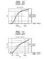
- FIG. 10 of the accompanying drawings is a typically characteristic curve, illustrating the relationship between the recording power P and the signal amplitude m.
- the signal amplitude m is approximated by formula (1) shown below as a function of the recording power P,
- FIG. 11 illustrates a typical relationship between the recording power P and the evaluation value P ⁇ m.
- the change in the signal amplitude relative to the change in the recording power is reduced as the recording power rises.
- the sensitivity to changes of amplitude falls.
- a predetermined factor ⁇ is introduced for the optimum recording power P wopt to be used for actual recording.
- the recording power is recommended to be used as reference for OPC.
- the value of P target is recorded in the disk information region of the optical disk.
- a test recording process is executed in the OPC region (recording test region) of the disk by using a predetermined random pattern, changing the recording power at and near P target within a range of P target ⁇ 10%, for instance. Then, the signal amplitude m corresponding to each recording power P is observed and the evaluation value P ⁇ m is computed.
- P t P thr ⁇ ⁇
- P wopt P t ⁇ ⁇
- a method of determining the relation of the evaluation value P ⁇ m and the recording power P within two observation ranges located near P target , e.g., one centered at a point slightly shifted to the lower power side and the other centered at a point slightly shifted to the higher power side from P target , and executing a predetermined computational process to improve the accuracy level of observation is also known.
- P f 1 that is slightly shifted from P target to the lower power side for one of the centers of power
- P f 2 that is slightly shifted from P target to the higher power side for the other center of power
- P t 1 and P t 2 are defined for the respective power centers as values obtained by determining the recording threshold powers P thr 1 and P thr 2 as the P intercepts from the relation (2) and multiplying them by a predetermined factor ⁇ .
- the recording power that is used for test recording by OPC can show a large discrepancy from a suitable power value depending on the characteristics of the recording film of the optical disk, the optical characteristics of the optical disk apparatus and the changes with time of the optical system such as those produced by stains.
- P f 1 and P f 2 of the recording powers as the power centers to be used by the apparatus for test recording can be shifted significantly from the values suited for OPC. Accordingly, the values observed at the two points of P f 1 and P f 2 can differ from the corresponding values contained in the information stored on the optical disk to a large extent.
- the power center slightly shifted from P target to the lower power side is defined as P f 1 and the power center slightly shifted from P target to the higher power side is defined as P f 2 as in the case of the above description of the prior art.
- the recording threshold powers P thr 1 and P thr 2 computed from the relation (2) for the respective power centers are multiplied by a predetermined factor ⁇ to determine P t 1 and P t 2.
- the recording power for recording information on an optical disk is lowered from the desired recording power level when the recording power is changed by degradation of the optical performance and stains of the optical system.
- the linearity of the evaluation value (P ⁇ m) gives way and hence the outcome obtained by linear approximation, using the observation points, is also deviated to a large extent.
- the object of the present invention to provide a recording power adjustment method that can reliably optimize the power level of the recording power and an optical disk apparatus configured to operate with such a method.
- a recording power adjustment method for recording information on an optical disk comprising the steps of: selecting at least three testing center recording powers P f (j: j ⁇ 3) according to disk information written on the optical disk in advance; recording a signal in a recording test region of the optical disk, with a recording power being shifted according to a testing recording power row P j (i) defined around each of the testing center recording powers P f (j); reproducing the signal recorded in the recording test region and detecting a reproduced signal amplitude row m j (i) corresponding to the recording power row P j (i), for each of the testing center recording powers; linearly approximating a relationship between the recording power row P j (i) and the row of multiplication products of corresponding values of the reproduced signal amplitude row m j (i) and the recording power row P j (i) and computationally determining a recording threshold power P thr (j) as an intersection of the linear approximation straight line and the recording power axis
- FIG. 1 is a schematic block diagram of an optical disk apparatus according to the present invention, illustrating the configuration thereof.
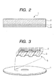
- FIG. 2 is a schematic cross-sectional view of an optical disk that can be used for the purpose of the present invention.
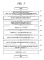
- FIG. 3 is an enlarged schematic perspective view of some of the information recording tracks of an optical disk.
- FIG. 4 is a flowchart of the first embodiment of recording power adjustment method according to the present invention.
- FIG. 5 is a graph illustrating the relationship of the intersection P thr (j) of the linear approximation straight line and the recording power axis relative to the center power P f (j) of each divisional region.
- FIG. 6 is a graph illustrating the relationship between P f (j) and P t (j).
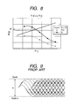
- FIG. 7 is a flowchart of the second embodiment of recording power adjustment method according to the present invention.
- FIG. 8 is a graph illustrating an example of polynomial approximation of the relationship of P t and P f of the second embodiment.
- FIG. 9 is a schematic illustration of observation of reproduced signal amplitude.
- FIG. 10 is a graph illustrating the recording power dependency of reproduced signal amplitude.
- FIG. 11 is a graph illustrating the relationship between recording power P and evaluation value P ⁇ m.
- FIG. 12 is a graph illustrating the relationship between recording test center power P f and Pt.
- FIG. 2 is a schematic cross-sectional view of an optical disk that can be used for the purpose of the present invention.
- the optical disk 1 includes a substrate 2 that is made of polycarbonate and an information recording layer 3 that is formed on the substrate 2 and includes a phase change recording film.
- the phase change recording film of the information recording layer 3 is replaced by a reflection film.
- a cover layer (light transmission layer) 4 having a thickness of t is formed on the information recording layer 3.
- the cover layer 4 is made of a plastic material and shows a thickness of t.
- the cover layer 4 is formed on the information recording layer 3 on the substrate 2 as a sheet of adhesive resin or ultraviolet setting resin by spin coating.
- FIG. 3 is an enlarged schematic perspective view of some of the information recording tracks of an optical disk 1.
- a helical information recording track is or coaxial information recording tracks are formed in the information recording layer 3 of the optical disk 1.
- the information recording track is or tracks are formed by means of a guide groove that provides physical undulations and information is recorded on the recessed parts or the protruding parts or both as marks produced by phase changes.
- the optical disk 1 is a read-only disk
- the information recording track 5 is or tracks 5 are preformed as array of pre-pits.
- FIG. 1 is a schematic block diagram of an optical disk apparatus according to the present invention, illustrating the configuration thereof.
- An optical disk 1 that is an optical recording medium is driven to rotate by a spindle motor 7 and information is recorded or reproduced as a light beam is irradiated onto the optical disk 1 from an optical pickup 6.
- the optical pickup 6 irradiates a light beam onto the optical disk 1. Then, the optical pickup 6 receives the light beam reflected by the optical disk 1 and converts the reflected light beam into an electric signal, and the electric signal is supplied to focusing/tracking processing circuit 8 and RF signal processing circuit 9.
- the optical pickup 6 is formed from a semiconductor laser, a collimator lens, a beam splitter, a quarter-wave plate and a spherical aberration correcting optical system for correcting spherical aberration and a spherical aberration correcting optical system drive mechanism for driving the optical system.
- the optical pickup 6 further includes an objective lens, a focusing/tracking actuator, a converging lens, a light detector and so on so that a light beam is appropriately converged on the information recording layer 3 of the optical disk 1.
- the spherical aberration correcting mechanism drive circuit 11 drives the spherical aberration correcting optical system drive mechanism in the optical pickup 6 to realize an optimum spherical aberration correcting condition when the cover layer 4 of the optical disk 1 involves an error and/or when the recording layer actually includes two or more than two recording layers.
- the focusing/tracking processing circuit 8 generates focusing error signal and/or tracking error signal by executing a predetermined arithmetic process according to the signal that is obtained from the light beam reflected from the information recording track 5 by photoelectric conversion.
- the focusing/tracking drive circuit 10 drives the focusing/tracking actuator for focusing/tracking control so as to make the light spot appropriately follow the information recording track 5 according to the focusing error signal and/or tracking error signal.
- the RF signal processing circuit 9 generates a reproduction information signal from the signal obtained from the light beam reflected from the information recording track 5 by photoelectric conversion.
- the RF signal processing circuit 9 has a feature of gauging the reproduced signal amplitude.
- the reproduced signal amplitude is gauged by sampling peak/bottom values by peak/bottom detection.
- techniques for gauging the reproduced signal amplitude are not limited to the technique of the above-described method.
- a technique of sampling the reproduced signal at a predetermined cycle period, determining the standard deviation of the sampled values and multiplying the standard deviation by a predetermined factor to determine the reproduced signal amplitude is also available.
- For gauging the reproduced signal amplitude a requirement that mark/non-mark of the recorded signal shows periodicity within a sufficiently small range relative to the sampling region or mark/non-mark shows randomness needs to be met. In other words, such a signal needs to be recorded. More specifically, a monotone signal, a random signal with a DSV (digital sum value) that is held sufficiently low may be used as such a recorded signal.
- DSV digital sum value
- the reproduced signal is sampled for a predetermined number of samples by means of the channel clock of the recorded data row or a clock of integer times of the channel clock. If each sampled value is Xi and the number of samples is n, the standard deviation (StdV) of the sampled signal levels is determined by the formula shown below.
- the reproduced signal amplitude follows peaks/bottoms when the reflectivity is abnormally large or small due to scars or dirt on the track. Additionally, since peak/bottom values converge to ordinary values with a time constant, the amplitude can be observed to be large in the region to make it impossible to accurately gauge the signal amplitude. Therefore, the greatest advantage of this method is to minimize the influence of any abnormality in the reflectivity within the gauging region due to scars, dirt and/or defects.
- the controller 12 is a control circuit for controlling the components of the apparatus. More specifically, the controller 12 controls the revolutions per unit time of the optical disk 1 and the operation of turning on/off the semiconductor laser that is the light source in the optical pickup 6. Additionally, the controller 12 controls the power for each operation and each of the servo systems and adjusts the recording power as will be described in greater detail hereinafter. More specifically, when controlling/adjusting the recording power, the controller 12 controls the recording power of the test recording process, the sequence of the test recording process and the reproduced signal gauging process and adjusts the recording power to an optimum level.
- the recording power adjustment method by test recording according to the invention of an optical disk apparatus having the above-described configuration will be described below.
- the optical disk 1 is driven to rotate at a constant linear velocity or with a constant number of revolutions per unit time by the spindle motor 7 under the control of the controller 12.
- the controller 12 After completing a pre-process such as a single full turn of the optical disk 1 and/or turning on/off of the semiconductor laser, the controller 12 appropriately processes the obtained focusing signal by means of the focusing processing circuit 8 and subsequently controls the focus by drawing in the focus according to the obtained focusing error signal.
- the controller 12 confirms the locked focus and processes the obtained tracking signal by means of the tracking processing circuit 8 and sequentially controls the tracking by drawing in the tracking according to the obtained tracking error signal.
- the controller 12 moves the optical pickup 6 into the lead-in area of the optical disk 1, reads out the various data recorded in the lead-in area from the optical disk 1 and stores the data in a memory (not illustrated).
- the data acquired in this stage includes ID information of the optical disk 1 and information necessary for defining the optimum recording power.
- the adjustment operation is conducted under the control of the controller 12.
- the controller 12 moves the light spot of the optical pickup 6 to the recording test region of the optical disk 1.
- the data on the two neighboring tracks at the opposite sides of the track for gauging, if any, is erased in view of the influence thereof to the operation of gauging the amplitude due to cross talks (S1).
- the two neighboring tracks of the recording test region are preferably in an unrecorded state.
- the recording power is defined according to the data acquired from the lead-in area. Additionally, for a test recording operation, the recording test region of the optical disk is divided into a plurality of divisional regions and a signal is recorded in the divisional regions with different recording power levels (S2).
- the recording pattern to be used for the test recording may be the same as the one described above for the conventional art.
- the range to be divided and the dividing pitch of the recording power are selected on the basis of the computed values to determine the row of P(i), or the recording power row for test recording.
- the recording test region is divided corresponding to the divided state of the recording power.
- the range to be divided of the recording power is from P thr to P wopt and divided into a plurality of sub-ranges to define the recording power row.
- the lower limit value of the low power side of the divided recording power may not be defined to be P thr as above. Normally, changes in the optical characteristics and changes in the recording power due to stains reduce the power of irradiation of a light beam. Therefore, the range of the low power side may well be determined by taking this fact into consideration.
- the levels of recording power are preferably differentiated by less than (1.1 ⁇ P target - 0.9 ⁇ P target ) / 5 within the recording power range from P target / ⁇ to P target ⁇ ⁇ .
- the above formula is used to define the recording power row P(i) for this embodiment.
- the region to be used for test recording is preferably not greater than a full round track of the optical disk from the viewpoint of reducing the time to be spent for the test recording.
- the divisor for dividing a full round track may be automatically determined. For example, a full round track may be divided by a divisor of 25.
- the levels of recording power are defined as described above and the recording process of test recording is executed with the different levels of recording power. Subsequently, the recorded signals recorded in the recording test region of the optical disk is reproduced to observe the reproduced signal amplitudes m(i) that correspond to the recording power row P(i) (S3).
- the RF signal amplitude is gauged by the RF signal processing circuit 9 as described above.
- the amplitude gauging method is not particularly limited, the technique of gauging the amplitude by multiplying the standard deviation of the sampled amplitude values by a predetermined factor is used for this embodiment.
- the reproduced signal is sampled by means of a sampling clock for gauging the amplitude.
- a sampling clock for gauging the amplitude.
- the computation of the formula (3) is conducted while sampling the reproduced signal within a single divisional region by means of the clock and the standard deviation of the amplitude levels is computationally determined.
- the signal to be observed is a sine wave
- the amplitude is determined by multiplying by 2 ⁇ 2 because the computed result is the effective value of the sine wave.
- the computed value does not agree with the amplitude observed by peak/bottom detection because there are signals whose amplitude is reduced by inter-code interference.
- a value equivalent to the amplitude observed by peak/bottom detection is obtained by further multiplying by 1.5, or multiplying by 1.5 ⁇ 2 ⁇ 2.
- the reproduced signal contains a noise component as a matter of course and hence the amplitude can be gauged only by means of the noise. Therefore, it is desirable to prepare a divisional region that is not used for recording and the result of amplitude observation in this region is subtracted from each of the observed values as offset value of each of the gauged amplitudes.
- the reproduced signal amplitudes m(i) that corresponds to the respective recording powers P(i) are obtained by means of the above-described technique as illustrated in FIG. 10.
- the relation as illustrated in FIG. 11 is obtained by plotting the relations of P(i) ⁇ m(i) v.s. P(i) from the obtained results (S4).
- the range of recording power (the range from P thr to P wopt in this instance) is divided at a pitch of 10% of the center power information P target for test recording and each center power is defined by P f (j).
- a plurality of recording powers are selected from the above-described recording power row P(i) and the center powers thereof are defined by P f (j).
- the number of selected recording powers is preferably not less than three. This means that three or more than three center powers P f are selected from the range of recording power.
- a row of recording power P j (i) is defined within the range of ⁇ 10% of each P f (j) or the range of ⁇ 10% of P target for the centers P f (j) and m j (i) ⁇ P j (i) is computed from the amplitude information m j (i) corresponding to the P j (i) (on the basis of the relation of P(i) and m(i) of S3).
- the recording power row P(i) may alternatively be selected after defining the center powers P f (j) in such a way that the defined ranges of recording power that are centered respectively at the center powers P f (j) are located within the overall range of recording power (the range from P thr to P wopt in this instance).
- the amplitude data of the power range used for the computation may contain amplitude information on the recording power that is too low to record a signal. Then, the linearity of the linear approximation used for computing P thr (j) may become a problem.
- the value of P thr (j) is excluded from the subsequent data processing operations to realize an accurate OPC process. For example, by seeing the computed P thr (j) in FIG. 5, it will be found that the value of P thr (0) is higher than 0.9 ⁇ P f (0) (the straight line indicated by the broken line in FIG. 5 is the line of 0.9 ⁇ P f (j)).
- the medium information that relates to OPC and described in the disk information is the information obtained by the manufacturer of the medium as a result of a gauging operation.
- the manufacturer of the medium may have used an evaluation tester, observed the amplitude dependency within a range of power extending to the opposite sides of the recording power P target and determined P thr that is the intercept of the recording power axis by linear approximation of P ⁇ m v.s. P as described above.
- the ratio of P t to P thr (P t / P thr ) is expressed by ⁇ .
- P v.s. P ⁇ m normally does not form a complete straight line and shows a relation that depends on the center value of the recording power that is linearly approximated and provides a different intercept with the inclination/power axis.
- the optical disk apparatus that uses this optical disk operates for gauging/processing, using a recording power having the same significance as P target in terms of amplitude changing characteristics, and determines P thr , P t ' that is determined by multiplying by ⁇ agrees with the center power P target for test recording.
- the optical disk apparatus operates for gauging/process, using a recording power having a significance different from P target and determines P thr , P t ' that is determined by multiplying by ⁇ does not agree with the center power P target for test recording.
- the recording power P wopt is determined by multiplying the ultimately obtained P t by ⁇ that is read out from the DI information (S9).
- the controller 12 of the optical disk apparatus defines the P wopt and employs the P wopt for the subsequent operation of recording information. There may be an optical disk apparatus that further and minutely adjusts the recording power on the basis of the detected P wopt .
- FIG. 8 illustrates approximation curves obtained by cubic approximation of the relation of P t (i) and P f (i).
- the process flow of FIG. 7 is the same as the process flow of FIG. 4 except the use of polynomial approximation and hence will not be described here any further.
- a method of adjusting the optimum recording power (OPC) by test recording to execute a highly accurate OPC process by conducting a test recording operation only once without repeating a test recording operation depending on the outcome thereof. Then, as a result, it is possible to reduce the adjustment time required at the time of putting an optical disk into an optical disk apparatus and at the time of starting an optical disk apparatus so as to make the optical disk apparatus comfortable for users.
- OPC optimum recording power
- a recording power row P(i) is selected and a signal is recorded in a recording test region of an optical disk, while shifting a recording power, to detect a reproduced signal amplitude row m(i) that corresponds to the recording power row P(i).
- the relation of the recording power row P(i) and the row of multiplication products P(i) ⁇ m(i) is linearly approximated and the intersection of the linear approximation straight line and the recording power axis is computationally determined as recording threshold power P thr , for at least three recording power rows P j (i) that are centered at P f (j) in the recording power row P(i) within a defined range.
- the recording power P t (j) is computed as a multiplication product of the recording threshold power P tnr (j) and a factor ⁇ contained in the disk information, for each recording power row P j (i).
- the optimum recording power P wopt is computationally determined according to the at least three recording powers P t (j).
Landscapes
- Physics & Mathematics (AREA)
- Optics & Photonics (AREA)
- Optical Recording Or Reproduction (AREA)
- Optical Head (AREA)
Applications Claiming Priority (1)
| Application Number | Priority Date | Filing Date | Title |
|---|---|---|---|
| JP2006189153A JP2008016165A (ja) | 2006-07-10 | 2006-07-10 | 記録パワー調整方法及び光ディスク装置 |
Publications (2)
| Publication Number | Publication Date |
|---|---|
| EP1879189A2 true EP1879189A2 (de) | 2008-01-16 |
| EP1879189A3 EP1879189A3 (de) | 2008-01-23 |
Family
ID=38606468
Family Applications (1)
| Application Number | Title | Priority Date | Filing Date |
|---|---|---|---|
| EP07110624A Withdrawn EP1879189A3 (de) | 2006-07-10 | 2007-06-20 | Verfahren zur Anpassung der Aufnahmeleistung einer optischen Platte und für den Betrieb damit angepasste optische Plattenvorrichtung |
Country Status (3)
| Country | Link |
|---|---|
| US (1) | US7466638B2 (de) |
| EP (1) | EP1879189A3 (de) |
| JP (1) | JP2008016165A (de) |
Families Citing this family (2)
| Publication number | Priority date | Publication date | Assignee | Title |
|---|---|---|---|---|
| JP2007122815A (ja) * | 2005-10-28 | 2007-05-17 | Canon Inc | 光ディスク装置の球面収差及びフォーカスオフセット調整方法、それを用いた光ディスク装置 |
| JP5421669B2 (ja) * | 2009-06-23 | 2014-02-19 | アズビル株式会社 | 振幅算出装置および振幅算出方法 |
Family Cites Families (23)
| Publication number | Priority date | Publication date | Assignee | Title |
|---|---|---|---|---|
| US5233578A (en) | 1988-12-28 | 1993-08-03 | Canon Kabushiki Kaisha | Method of recording information on a recording medium having at least two magnetic layers |
| EP0387052B1 (de) | 1989-03-09 | 1995-09-20 | Canon Kabushiki Kaisha | Magnetooptisches Aufzeichnungsgerät mit Mitteln zur Verzögerung des Eingangssignales zur Verhinderung von Bitverschiebung |
| JP3035034B2 (ja) * | 1991-11-19 | 2000-04-17 | パイオニア株式会社 | レーザダイオードの放射パワー制御装置 |
| EP0559391B1 (de) | 1992-03-03 | 1998-06-03 | Canon Kabushiki Kaisha | Magneto-optisches Aufzeichnungs- und Wiedergabeverfahren und Gerät |
| JP3457463B2 (ja) * | 1996-04-26 | 2003-10-20 | 富士通株式会社 | 光学的記憶装置 |
| JPH1092037A (ja) | 1996-09-19 | 1998-04-10 | Canon Inc | 光磁気記録再生方法及び光磁気記録再生装置 |
| JPH10334534A (ja) | 1997-05-28 | 1998-12-18 | Canon Inc | 光磁気記録再生方法及び光磁気記録再生装置 |
| JPH1131343A (ja) | 1997-07-08 | 1999-02-02 | Canon Inc | 光磁気記録再生方法及び光磁気記録再生装置と光磁気記録方法 |
| JPH11134732A (ja) | 1997-08-29 | 1999-05-21 | Canon Inc | 情報記録再生方法 |
| JP3703315B2 (ja) | 1997-10-01 | 2005-10-05 | キヤノン株式会社 | 光磁気記録再生方法及びその再生装置 |
| JPH11353732A (ja) | 1998-06-10 | 1999-12-24 | Canon Inc | 光磁気記録再生方法及び装置 |
| US6639890B1 (en) * | 1998-06-29 | 2003-10-28 | Olympus Optical | Optical disk drive for precisely adjusting the intensity of laser light irradiated onto an optical disk |
| JP2000200450A (ja) | 1998-10-30 | 2000-07-18 | Canon Inc | 光磁気記録再生方法及び装置 |
| JP2000298888A (ja) | 1999-04-15 | 2000-10-24 | Canon Inc | 光磁気記録媒体 |
| JP2001023254A (ja) | 1999-07-02 | 2001-01-26 | Canon Inc | 光磁気記録テスト方法及び光磁気記録再生装置 |
| JP3863331B2 (ja) | 1999-12-24 | 2006-12-27 | 株式会社リコー | 光学的情報記録再生方法及び光学的情報記録再生装置 |
| JP2002216403A (ja) | 2001-01-16 | 2002-08-02 | Canon Inc | 光磁気ディスクのアニール方法、及び光磁気ディスク |
| JP2003248932A (ja) | 2002-02-21 | 2003-09-05 | Victor Co Of Japan Ltd | 光ディスク記録再生装置 |
| JP2003317344A (ja) | 2002-04-26 | 2003-11-07 | Canon Inc | 光磁気記録方法、及び光磁気記録装置 |
| JP2005011385A (ja) | 2003-06-16 | 2005-01-13 | Canon Inc | 磁区拡大型光磁気再生方法及び装置 |
| JP2005267802A (ja) | 2004-03-19 | 2005-09-29 | Sony Corp | ディスクドライブ装置及び記録パワー設定方法 |
| ES2315943T3 (es) | 2004-12-23 | 2009-04-01 | Koninklijke Philips Electronics N.V. | Procedimiento de seleccion de un parametro de escritura optimo de un aparato de grabacion optica. |
| JP2007122815A (ja) | 2005-10-28 | 2007-05-17 | Canon Inc | 光ディスク装置の球面収差及びフォーカスオフセット調整方法、それを用いた光ディスク装置 |
-
2006
- 2006-07-10 JP JP2006189153A patent/JP2008016165A/ja active Pending
-
2007
- 2007-06-08 US US11/760,462 patent/US7466638B2/en not_active Expired - Fee Related
- 2007-06-20 EP EP07110624A patent/EP1879189A3/de not_active Withdrawn
Also Published As
| Publication number | Publication date |
|---|---|
| US7466638B2 (en) | 2008-12-16 |
| JP2008016165A (ja) | 2008-01-24 |
| US20080008064A1 (en) | 2008-01-10 |
| EP1879189A3 (de) | 2008-01-23 |
Similar Documents
| Publication | Publication Date | Title |
|---|---|---|
| US8385179B2 (en) | Optical disk device and optical disk discriminating method | |
| CN100409329C (zh) | 光信息记录装置 | |
| US7782722B2 (en) | Method of adjusting spherical aberration and focus offset and information recording/reproduction apparatus using the same | |
| KR20070053114A (ko) | 재생 장치, 구면수차 보정치 및 포커스 바이어스 조정 방법 | |
| US7680003B2 (en) | Optical disk device with disk type recognition | |
| US6970405B2 (en) | Optical recording/reproducing apparatus | |
| JP4145593B2 (ja) | 球面収差補正装置及び球面収差補正方法 | |
| CN101447202B (zh) | 可测量球面像差修正值的方法 | |
| EP1394785B1 (de) | Verfahren und Gerät zur Korrektur der Neigungs des Lichtstrahls, der ein optisches Aufzeichnungsmedium abtastet | |
| US7466638B2 (en) | Optical disk recording power adjustment method and optical disk apparatus adapted to operate with the same | |
| EP1385156B1 (de) | Verfahren und Gerät zur Korrektur der sphärischen Aberration | |
| US8355308B2 (en) | Optical recording medium and recording and reading method of optical recording medium | |
| US7719940B2 (en) | Tilt correcting apparatus and method, information recording apparatus, and information recording/reproducing apparatus | |
| JP2007122815A (ja) | 光ディスク装置の球面収差及びフォーカスオフセット調整方法、それを用いた光ディスク装置 | |
| JP4224506B2 (ja) | 光ディスク装置 | |
| EP1376550A2 (de) | Schiefstellungskorrekturgerät | |
| US7630278B2 (en) | Focusing control method for reading/writing optical disc | |
| US20080175107A1 (en) | Focusing control method for reading/writing optical disc | |
| CN100483520C (zh) | 光盘装置及光盘半导体 | |
| EP1713068A1 (de) | Optische Lesekopfvorrichtung und Steuerverfahren dafür | |
| RU2321081C2 (ru) | Устройство регулирования фокуса | |
| US20060215521A1 (en) | Disc drive apparatus | |
| KR100948145B1 (ko) | 포커스 서보 제어 방법 및 장치와 이를 이용한 광 디스크드라이브 | |
| US7957242B2 (en) | Servo parameter detection method and optical pickup device using the same | |
| KR20040074488A (ko) | 광 재생 및 기록 장치의 틸트각 측정 및 보상 방법 |
Legal Events
| Date | Code | Title | Description |
|---|---|---|---|
| PUAI | Public reference made under article 153(3) epc to a published international application that has entered the european phase |
Free format text: ORIGINAL CODE: 0009012 |
|
| PUAL | Search report despatched |
Free format text: ORIGINAL CODE: 0009013 |
|
| AK | Designated contracting states |
Kind code of ref document: A2 Designated state(s): AT BE BG CH CY CZ DE DK EE ES FI FR GB GR HU IE IS IT LI LT LU LV MC MT NL PL PT RO SE SI SK TR |
|
| AX | Request for extension of the european patent |
Extension state: AL BA HR MK YU |
|
| AK | Designated contracting states |
Kind code of ref document: A3 Designated state(s): AT BE BG CH CY CZ DE DK EE ES FI FR GB GR HU IE IS IT LI LT LU LV MC MT NL PL PT RO SE SI SK TR |
|
| AX | Request for extension of the european patent |
Extension state: AL BA HR MK YU |
|
| STAA | Information on the status of an ep patent application or granted ep patent |
Free format text: STATUS: THE APPLICATION HAS BEEN WITHDRAWN |
|
| 18W | Application withdrawn |
Effective date: 20080317 |