EP1875858B1 - Vorrichtung zur Blutungsdetektion - Google Patents
Vorrichtung zur Blutungsdetektion Download PDFInfo
- Publication number
- EP1875858B1 EP1875858B1 EP07111530.7A EP07111530A EP1875858B1 EP 1875858 B1 EP1875858 B1 EP 1875858B1 EP 07111530 A EP07111530 A EP 07111530A EP 1875858 B1 EP1875858 B1 EP 1875858B1
- Authority
- EP
- European Patent Office
- Prior art keywords
- light
- detection according
- hemorrhage detection
- blood
- fixing means
- Prior art date
- Legal status (The legal status is an assumption and is not a legal conclusion. Google has not performed a legal analysis and makes no representation as to the accuracy of the status listed.)
- Active
Links
- 230000000740 bleeding effect Effects 0.000 title claims description 37
- 238000001514 detection method Methods 0.000 claims description 78
- 208000032843 Hemorrhage Diseases 0.000 claims description 52
- 210000000056 organ Anatomy 0.000 claims description 45
- 239000008280 blood Substances 0.000 claims description 30
- 210000004369 blood Anatomy 0.000 claims description 30
- 239000000463 material Substances 0.000 claims description 7
- 238000012545 processing Methods 0.000 claims description 7
- 238000001429 visible spectrum Methods 0.000 claims description 6
- 230000023597 hemostasis Effects 0.000 claims description 3
- 208000034158 bleeding Diseases 0.000 description 35
- 210000001035 gastrointestinal tract Anatomy 0.000 description 17
- 230000005540 biological transmission Effects 0.000 description 8
- 238000000862 absorption spectrum Methods 0.000 description 7
- 238000010521 absorption reaction Methods 0.000 description 5
- 230000001419 dependent effect Effects 0.000 description 5
- 238000011156 evaluation Methods 0.000 description 5
- 238000012544 monitoring process Methods 0.000 description 5
- 238000000354 decomposition reaction Methods 0.000 description 4
- 238000005259 measurement Methods 0.000 description 4
- 238000000034 method Methods 0.000 description 4
- 208000007107 Stomach Ulcer Diseases 0.000 description 3
- 239000000560 biocompatible material Substances 0.000 description 3
- 208000000718 duodenal ulcer Diseases 0.000 description 3
- 238000005538 encapsulation Methods 0.000 description 3
- 208000037265 diseases, disorders, signs and symptoms Diseases 0.000 description 2
- 208000035475 disorder Diseases 0.000 description 2
- 239000000975 dye Substances 0.000 description 2
- 210000003238 esophagus Anatomy 0.000 description 2
- 230000002496 gastric effect Effects 0.000 description 2
- 201000005917 gastric ulcer Diseases 0.000 description 2
- 230000003287 optical effect Effects 0.000 description 2
- 230000000306 recurrent effect Effects 0.000 description 2
- 230000011664 signaling Effects 0.000 description 2
- 210000002784 stomach Anatomy 0.000 description 2
- 238000011282 treatment Methods 0.000 description 2
- 208000000624 Esophageal and Gastric Varices Diseases 0.000 description 1
- 102000001554 Hemoglobins Human genes 0.000 description 1
- 108010054147 Hemoglobins Proteins 0.000 description 1
- 206010028980 Neoplasm Diseases 0.000 description 1
- 206010051077 Post procedural haemorrhage Diseases 0.000 description 1
- 206010056091 Varices oesophageal Diseases 0.000 description 1
- 206010046996 Varicose vein Diseases 0.000 description 1
- 230000001154 acute effect Effects 0.000 description 1
- QVGXLLKOCUKJST-UHFFFAOYSA-N atomic oxygen Chemical compound [O] QVGXLLKOCUKJST-UHFFFAOYSA-N 0.000 description 1
- 239000002775 capsule Substances 0.000 description 1
- 238000006243 chemical reaction Methods 0.000 description 1
- 210000001198 duodenum Anatomy 0.000 description 1
- 238000012277 endoscopic treatment Methods 0.000 description 1
- 208000024170 esophageal varices Diseases 0.000 description 1
- 201000010120 esophageal varix Diseases 0.000 description 1
- 229910052760 oxygen Inorganic materials 0.000 description 1
- 239000001301 oxygen Substances 0.000 description 1
- 238000001228 spectrum Methods 0.000 description 1
- 238000012546 transfer Methods 0.000 description 1
- 208000027185 varicose disease Diseases 0.000 description 1
Images

Classifications
-
- A—HUMAN NECESSITIES
- A61—MEDICAL OR VETERINARY SCIENCE; HYGIENE
- A61B—DIAGNOSIS; SURGERY; IDENTIFICATION
- A61B5/00—Measuring for diagnostic purposes; Identification of persons
- A61B5/0059—Measuring for diagnostic purposes; Identification of persons using light, e.g. diagnosis by transillumination, diascopy, fluorescence
- A61B5/0082—Measuring for diagnostic purposes; Identification of persons using light, e.g. diagnosis by transillumination, diascopy, fluorescence adapted for particular medical purposes
- A61B5/0084—Measuring for diagnostic purposes; Identification of persons using light, e.g. diagnosis by transillumination, diascopy, fluorescence adapted for particular medical purposes for introduction into the body, e.g. by catheters
-
- A—HUMAN NECESSITIES
- A61—MEDICAL OR VETERINARY SCIENCE; HYGIENE
- A61B—DIAGNOSIS; SURGERY; IDENTIFICATION
- A61B5/00—Measuring for diagnostic purposes; Identification of persons
- A61B5/07—Endoradiosondes
- A61B5/073—Intestinal transmitters
-
- A—HUMAN NECESSITIES
- A61—MEDICAL OR VETERINARY SCIENCE; HYGIENE
- A61B—DIAGNOSIS; SURGERY; IDENTIFICATION
- A61B5/00—Measuring for diagnostic purposes; Identification of persons
- A61B5/0059—Measuring for diagnostic purposes; Identification of persons using light, e.g. diagnosis by transillumination, diascopy, fluorescence
- A61B5/0082—Measuring for diagnostic purposes; Identification of persons using light, e.g. diagnosis by transillumination, diascopy, fluorescence adapted for particular medical purposes
- A61B5/0084—Measuring for diagnostic purposes; Identification of persons using light, e.g. diagnosis by transillumination, diascopy, fluorescence adapted for particular medical purposes for introduction into the body, e.g. by catheters
- A61B5/0086—Measuring for diagnostic purposes; Identification of persons using light, e.g. diagnosis by transillumination, diascopy, fluorescence adapted for particular medical purposes for introduction into the body, e.g. by catheters using infrared radiation
Definitions
- the present invention relates to a device for detecting bleeding.
- Bleeding in the digestive tract can occur in various disorders of the digestive tract, e.g. in esophageal varices or gastric and duodenal ulcers. Even after endoscopic treatment of such disorders, recurrent bleeding often occurs, which is a serious complication. Recurrent bleeding can occur several hours or days after treatment, making it difficult to detect. Bleeding in the digestive tract can lead to an acute emergency situation, since they can lead to a large blood loss unnoticed. Since no continuous monitoring option is currently available, it is often too late to detect such bleeding.
- One known method detects bleeding by detecting dyes that have been previously added to the blood. However, due to the limited plasma half-life of the dye, this method does not function for more than a few hours, and is therefore not suitable for postoperative bleeding monitoring.
- the US 5833603 discloses an apparatus for detecting oxygen saturation for detecting hemoglobin in blood. For detection, light in the range of 660nm and light in the range of 800nm is emitted.
- the US 2005/0154277 A1 discloses a swallowable capsule with the Gastrointestinalblutungen are detectable. This light is emitted in the range of 660nm and 940nm.
- US 2004/017664 discloses a device for taking a blood sample.
- US 6611320 B1 discloses a method for detecting a blood characteristic.
- US 5131398 discloses an apparatus and method for tumor detection.
- the object of the invention is achieved with a device for the detection of bleeding according to claim 1.
- a detection device for detecting the presence of blood is fastened by means of a fastening device, preferably a clip, inside a hollow organ for a certain duration.
- a fastening device preferably a clip
- the clip is designed such that it can be transported by means of an endoscope into the interior of a hollow organ, and can be fixed to an inner wall of the hollow organ.
- a clip is for example from the US 6,428,548 , another application of the applicant, known.
- the fastening device does not necessarily have to be a clip, but can be any device that can be fastened or anchored inside a hollow organ.
- the fastening device is formed of a biocompatible material.
- the attachment means may be formed of a biodegradable material which decomposes after a certain time. Since the fastening device separates itself from the inner wall of the organ due to their decomposition after a certain time, the fastening device does not need to be replaced by a device, As an endoscope, are removed from the interior of the hollow organ, but if it is in the hollow organ, for example, the digestive tract, naturally excreted on this.
- the biodegradable material is chosen so that the fastening device separates due to their decomposition, immediately or shortly after the desired observation time of the inner wall of the organ.
- the detection device measures the presence of blood by measuring emitted light which is absorbed or reflected by the contents in the hollow organ or hollow organ wall.
- the detection device emits light of a predetermined wavelength, which is at least partially absorbed or reflected in the interior of the hollow organ, and detects the reflected light via a photosensitive sensor. Since blood has a characteristic absorption spectrum which differs from the absorption spectrum of the "normal" organ content, it can be determined on the basis of the detected reflections whether or not there is blood inside the hollow organ.
- the detection device has at least one light-sensitive sensor. This photosensitive sensor is preferably a photodiode or a phototransistor. Furthermore, the detection device has at least one light source.
- the detection device preferably has at least two light sources, of which at least one emits light in the UV range, and emits at least one other light in the red region of the visible spectrum.
- the light source / light sources is / are designed as LED (s).
- the device for detecting bleeding further comprises a transmitting unit, which is connected to the detection device, for transmitting data detected by the detection device, and a receiving unit for receiving the data transmitted by the transmitting unit.
- the transmitting unit is connected via a data-transmitting cable with the detection device.
- the detection device can be anchored or fixed to the transmitting unit or formed integrally therewith.
- the detection device, the transmitting unit and the fastening device are connected to one another in such a way that they form a compact unit.
- the receiving unit is preferably located outside the body, that is extracorporeal.
- the transmission of data from the transmitting unit to the receiving unit is wireless.
- the receiving unit for displaying the received signals is connected to an optical device and / or an acoustic signaling device, such as a screen or a loudspeaker.
- the receiving unit may also have a connection to a local, regional or supraregional network, e.g. via DECT, BlueTooth, WLAN, GSM or satellite in order to transmit the signals received from the transmitting unit to third parties, e.g. a doctor or an emergency call center to be able to transfer.
- the detection device and / or the transmitting unit is formed encapsulated.
- this encapsulation consists of a biocompatible material.
- the fastening device itself is a means for haemostasis of a source of bleeding.
- This can be realized, for example, by forming the fastening device as an endoscopic hemostasis clip.
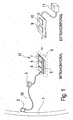
- Fig. 1 shows the device for bleeding detection according to the embodiment of the invention in a schematic view.
- FIG. 13 is a schematic view of a detection device of the bleeding detection device according to the embodiment of the invention.
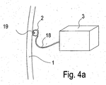
- Fig. 3 is a schematic view of the detection device and a transmitting unit of the device for detecting bleeding according to the embodiment of the invention.
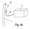
- Fig. 4a and 4b each show the device for bleeding detection according to the embodiment in fastening or detection position in the interior of a hollow organ.
- the device for detecting bleeding consists essentially of an intracorporeal part and an extracorporeal part.
- the intracorporeal part will be described first.
- the intracorporeal part comprises a fastening element 2, which in this embodiment is a clip or anchor, which is attached to an inner wall of the hollow organ, which in this embodiment is the digestive tract.
- a detection device 3 is connected via a connecting element 18, e.g. Rope or the like, connected.
- the detection device 3 consists of two light sources, one of which emits light in the UV range and the other light in the red region of the visible spectrum, and a photosensitive sensor, such as a photodiode or a phototransistor.
- the light sources send clocked or sequentially light in the interior of the hollow organ, in which the light is absorbed and reflected, and the photosensitive sensor detects the transmitted or reflected in the interior light.
- the fastening device 2 is designed as a stent-shaped structure.
- the fastening device 2 can fix the detection device 3 in a tubular hollow organ, e.g. in the duodenum to monitor diffuse sources of bleeding in the stomach or esophagus.
- the connecting element 18, which connects the detection device 3 with the fastening element 2 can be designed as a cable or the like.
- the connecting element 18 may be made of a decomposing material, eg, a biodegradable material, which decomposes over time.
- the decomposition time is determined depending on the organ and application so that the connecting element 18 only after elapse, preferably immediately after elapse, a reasonable observation time, the fastener 2 separates from the detection device 3. Through this Measure the detection device 3 separated from the fastener 2, of course, be eliminated through the digestive tract.
- the detection device 3 is connected via a data transmission cable to a transmission unit 17, so that signals can be transmitted between the light-sensitive sensor and the transmission unit 17.
- the detection device can also be anchored in the transmission unit 17, or integrally formed therewith.
- the transmitting unit 17 consists essentially of a data processing unit 4, an analog / digital converter 5, a power source 6, e.g. a battery, and a transmitter 7.
- the data processing unit 4 controls the detection means 3, the A / D converter 5 and the transmitter 7, and respectively, evaluates the data obtained from the photosensitive sensor.
- the A / D converter 5 converts the analog signals sent by the detection device 3 into digital signals, and the transmitter 7 transmits the data evaluated by the data processing unit 4 to a receiving unit 9.
- the data transmitted by the transmitter 7 can, for example, be measured values, status information or event signals, eg the event of the occurrence of a bleeding, his.
- the transmission unit 17 is surrounded by an encapsulation 8 in order to protect the elements of the transmission unit 17.
- the encapsulation is formed from a biocompatible material.
- the extracorporeal part consists essentially of a receiving unit 9, an interface 10 and an evaluation unit 11.
- the receiving unit 9 receives data sent by the transmitter 7 through a wireless transmission.
- the received by the receiving unit in this way Data can be evaluated or displayed by means of the interface 10 at an evaluation unit 11.
- the evaluation unit 11 can be, for example, an optical device or an acoustic signaling device, such as, for example, a display or a loudspeaker.
- the data received by the receiving unit can be transmitted by means of the interface 10 to third parties, for example a doctor or an emergency call center.
- the intracorporeal part consisting of anchor 2, detection device 3 and transmitting unit 17 is introduced by means of an endoscope into the digestive tract.
- the anchor 2 is attached by means of the endoscope to an inner wall of the digestive tract.
- the detection device 3 and the transmitting unit 17 are fixed by the armature 2 in the interior of the digestive tract.
- the detection device 3 detects whether blood is present in the digestive tract or not.
- the two light sources of the detection device 3, which emit light of a predetermined wavelength are driven by the receiving unit 4 such that each light source emits light in succession, one light source light in the UV range, and the other light source light in the red range of the visible spectrum.
- the light emitted from the light sources exits into the interior of the digestive tract, and is absorbed or reflected by the contents in the internal space.
- the light-sensitive sensor in the form of a photodiode or phototransistor formed in the detection device 3 detects the light transmitted or reflected in the interior of the digestive tract and generates a sensor signal on the basis of the detected light. Thus, a sensor signal is generated for each light source. If it is Blood is in the interior of the digestive tract, the light emitted by the light sources is absorbed differently than when there is no blood in the digestive tract, since blood has a quite characteristic absorption spectrum, which differs from the absorption spectrum of the "normal" organ content.
- the light reflected in the internal space, which is received by the photosensitive sensor differs depending on the presence of blood in the internal space, and hence the sensor signals emitted from the photosensitive sensor.
- the sensor signals emitted from the photosensitive sensor due to the different sensor signals of the photosensitive sensor, a presence or absence of blood can be deduced.
- the embodiment of the detection device 3 also allows the distinction between different forms of blood. Different manifestations of blood are, for example, clotted blood, venous blood or arterial blood.
- the detection device has at least one light source which emits light in the infrared region of the spectrum.
- the sensor signals emitted by the photosensitive sensor are then transmitted to the data processing unit 4 and the AD converter 5 where they are evaluated. Subsequently, the sensor 7 sends the evaluated and converted signals to the Receiving unit 9, which is part of the extracorporeal part and is located outside the body near the patient.
- the signals received by the receiving unit 9 are then output via an evaluation unit 11, such as a screen or a loudspeaker, which can be connected to the receiving unit 9 via an interface 10.
- the evaluation unit 11 can optionally transmit the signals received by the receiving unit 9 also via a network to third parties.
- the anchor 2 drops autonomously from the organ wall.
- the anchor can be designed in such a way that it loses its grip on the organ wall after application to the organ wall after a reasonable monitoring time, e.g. by dying off the gripped tissue or a rejection reaction of the gripped tissue, thus detaching itself from the organ wall.
- the armature 2 may be formed of a biodegradable material which decomposes over time.
- the decomposition time is determined depending on the organ so that the anchor 2 separates only after elapse, preferably immediately after elapse, a reasonable observation time of the inner wall of the organ. After detachment of the anchor from the organ wall of the intracorporeal part is naturally excreted through the digestive tract.
- the device may be removed again by means of an endoscope or other suitable device.
- the present invention can be applied to any hollow organ.
- a device other than an endoscope may be used.
- a device for detecting a hemorrhage has a detection device for detecting the presence of blood, which is connected to a fastening device.
- the fastening device is fastened to the inner wall of a hollow organ.
- the device has a transmitting unit with the data transmitted by the detection device can be transmitted to a receiving unit arranged outside the body.
- the detection device transmits light of specific wavelengths into the interior of the hollow organ and measures the presence of blood preferably by measuring the intensity of the light fraction absorbed by the content of the hollow organ with a light-sensitive sensor located in the detection device.
- a light-sensitive sensor located in the detection device.
- light of different wavelengths is emitted in succession and the intensity of the transmitted light component is measured in each case. This can be called measuring the absorption spectrum.
- Different types of organ contents have different, specific absorption spectra.
- the detection means may selectively emit light in the red region of the visible spectrum as well as ultraviolet light and with a photosensitive sensor the absorption of red light and the absorption of ultraviolet light through the light penetrated organ contents.
- the photosensitive sensor can consist of a single photosensor, which is sensitive to both red and ultraviolet light, or of two photosensors, one sensitive to red light and the other sensitive to ultraviolet light.
- Blood has a low absorption rate for red light but a high absorption rate for ultraviolet light.
- the red light is absorbed relatively less, while the ultraviolet light is relatively strongly absorbed.
- the sensor signal dependent on the intensity of the transmitted red light is thus opposite to the sensor signal dependent on the intensity of the transmitted ultraviolet light. If the quotient of the sensor signal dependent on the intensity of the transmitted red light and the sensor signal dependent on the intensity of the transmitted ultraviolet light is formed in the signal processing subsequent to the measurement, a single parameter arises, by means of which it is possible to conclude the presence of blood.
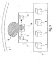
- Fig. 2 shows the detection device 3 of the device for bleeding detection according to the embodiment in a schematic view.
- the detection device 3 in this preferred embodiment, a light source 12, a photosensitive sensor 13 and a measuring gap or recess 14.
- the light source 12 is capable of emitting light of at least one wavelength.
- the light source 12 optionally emit light of one or more wavelengths.
- the light source 12 preferably has one or more LEDs.
- the light source 12, the light-sensitive sensor 13 and the measurement gap 14 are arranged relative to one another such that the light 15 emitted by the light source 12 exits the detection device 3 in the region of the measurement gap 14, runs a certain distance outside the detection device 3, at another point of the measuring gap 14 again enters the detection device 3 and then falls on the photosensitive sensor 13. While the emitted light 15 passes outside the detection means 3, it can pass through the organ contents 16 having specific absorption characteristics. In this way, specific absorption spectra can be measured and conclusions drawn on the nature of the screened organ contents 16.
- the measuring gap or the recess 14 may be designed differently, for example as a trough, notch, opening, hole or gap.
- Fig. 3 shows the detection device 3 and the transmitting unit 17 of the device for bleeding detection according to the embodiment in a schematic view.
- the detection device 3 is designed in this embodiment in one piece with the transmitting unit 17.
- the transmitting unit 17 has a data processing unit 4, an analog / digital converter 5, an energy source 6 and a transmitter 7.
- Fig. 4a shows the fastening device 2, the connecting element 18, the detection device 3 and the hollow organ wall 1.
- the hollow organ wall 1 in this case has a potential source of bleeding 19.
- the fastening device 2 is fastened to the potential source of bleeding 19 on the hollow organ wall 1 and therefore serves both to treat the potential source of bleeding 19 and to fix the detection device 3.
- the potential bleeding source 19 can be, for example, a stomach or duodenal ulcer.
- Fig. 4b shows the fastening device 2, the connecting element 18, the detection device 3 and the hollow organ wall 1.
- the hollow organ wall 1 in this case has a potential source of bleeding 19.
- the fastening device 2 is attached to the hollow organ wall 1 at a location other than the bleeding source 19 and therefore serves to secure the detection device 3 in the vicinity of the potential bleeding source 19 and not for the treatment of the potential bleeding source 19.
- the potential source of bleeding here be severely prone to bleeding, eg a treated or untreated varix in the esophagus or a treated or untreated gastric or duodenal ulcer.
- the fastening device 2 may also be formed as a stent-shaped structure.
Landscapes
- Life Sciences & Earth Sciences (AREA)
- Health & Medical Sciences (AREA)
- Medical Informatics (AREA)
- Biophysics (AREA)
- Pathology (AREA)
- Engineering & Computer Science (AREA)
- Biomedical Technology (AREA)
- Heart & Thoracic Surgery (AREA)
- Physics & Mathematics (AREA)
- Molecular Biology (AREA)
- Surgery (AREA)
- Animal Behavior & Ethology (AREA)
- General Health & Medical Sciences (AREA)
- Public Health (AREA)
- Veterinary Medicine (AREA)
- Measurement Of The Respiration, Hearing Ability, Form, And Blood Characteristics Of Living Organisms (AREA)
- Endoscopes (AREA)
- Surgical Instruments (AREA)
Applications Claiming Priority (1)
| Application Number | Priority Date | Filing Date | Title |
|---|---|---|---|
| DE102006000318A DE102006000318A1 (de) | 2006-07-03 | 2006-07-03 | Vorrichtung zur Blutungsdetektion |
Publications (3)
| Publication Number | Publication Date |
|---|---|
| EP1875858A2 EP1875858A2 (de) | 2008-01-09 |
| EP1875858A3 EP1875858A3 (de) | 2008-02-27 |
| EP1875858B1 true EP1875858B1 (de) | 2014-02-26 |
Family
ID=38658594
Family Applications (1)
| Application Number | Title | Priority Date | Filing Date |
|---|---|---|---|
| EP07111530.7A Active EP1875858B1 (de) | 2006-07-03 | 2007-07-02 | Vorrichtung zur Blutungsdetektion |
Country Status (5)
| Country | Link |
|---|---|
| US (1) | US7828730B2 (es) |
| EP (1) | EP1875858B1 (es) |
| JP (1) | JP5069049B2 (es) |
| DE (1) | DE102006000318A1 (es) |
| ES (1) | ES2450932T3 (es) |
Families Citing this family (8)
| Publication number | Priority date | Publication date | Assignee | Title |
|---|---|---|---|---|
| ES2620816T3 (es) * | 2007-11-12 | 2017-06-29 | Novineon Healthcare Technology Partners Gmbh | Dispositivo para la detección de hemorragias |
| BRPI1005285A2 (pt) * | 2009-01-29 | 2020-09-01 | Given Imaging Ltda | dispositivo, sistema e método de detecção de sangramento |
| WO2011066431A2 (en) * | 2009-11-25 | 2011-06-03 | Brigham And Women's Hospital, Inc. | System and method for wireless biosensor monitoring |
| EP2596756B1 (en) * | 2011-11-22 | 2014-02-26 | Ovesco Endoscopy AG | Implanting apparatus |
| TWI616180B (zh) | 2016-06-29 | 2018-03-01 | 國立成功大學 | 上消化道出血偵測裝置及方法 |
| JP7482150B2 (ja) | 2019-04-18 | 2024-05-13 | エンテラセンス リミテッド | バイオセンサカプセルおよびシステム |
| US20220047180A1 (en) * | 2020-08-13 | 2022-02-17 | The Chinese University Of Hong Kong | Apparatus and methods for monitoring concentrations of analytes in body fluid |
| EP4111940A1 (en) | 2021-07-01 | 2023-01-04 | Ovesco Endoscopy AG | Medical sensor and method for calibration |
Citations (7)
| Publication number | Priority date | Publication date | Assignee | Title |
|---|---|---|---|---|
| US4181610A (en) * | 1975-07-14 | 1980-01-01 | Takeda Chemical Industries, Ltd. | Blood leak detector suitable for use with artificial kidneys |
| DE3743920A1 (de) * | 1986-12-26 | 1988-07-14 | Olympus Optical Co | Endoskopeinrichtung |
| US5131398A (en) * | 1990-01-22 | 1992-07-21 | Mediscience Technology Corp. | Method and apparatus for distinguishing cancerous tissue from benign tumor tissue, benign tissue or normal tissue using native fluorescence |
| US6611320B1 (en) * | 1999-09-08 | 2003-08-26 | Optoq Ab | Method and apparatus |
| US20030210390A1 (en) * | 2002-05-07 | 2003-11-13 | O'mahony John J. | Blood leak detector for extracorporeal treatment system |
| US20040197771A1 (en) * | 2002-01-22 | 2004-10-07 | Powers Linda S. | Method and apparatus for detecting and imaging the presence of biological materials |
| US20050154277A1 (en) * | 2002-12-31 | 2005-07-14 | Jing Tang | Apparatus and methods of using built-in micro-spectroscopy micro-biosensors and specimen collection system for a wireless capsule in a biological body in vivo |
Family Cites Families (20)
| Publication number | Priority date | Publication date | Assignee | Title |
|---|---|---|---|---|
| JPH04347138A (ja) * | 1991-05-24 | 1992-12-02 | Olympus Optical Co Ltd | 医療用カプセル |
| JPH06114036A (ja) * | 1992-10-05 | 1994-04-26 | Olympus Optical Co Ltd | 医療用カプセル |
| JP3285235B2 (ja) * | 1992-11-05 | 2002-05-27 | オリンパス光学工業株式会社 | 生体内観察用カプセル装置 |
| US5833603A (en) * | 1996-03-13 | 1998-11-10 | Lipomatrix, Inc. | Implantable biosensing transponder |
| US6511477B2 (en) * | 1997-03-13 | 2003-01-28 | Biocardia, Inc. | Method of drug delivery to interstitial regions of the myocardium |
| US6428548B1 (en) | 1999-11-18 | 2002-08-06 | Russell F. Durgin | Apparatus and method for compressing body tissue |
| WO2002026103A2 (en) * | 2000-09-27 | 2002-04-04 | Given Imaging Ltd. | An immobilizable in vivo sensing device |
| DE60225669T2 (de) * | 2001-01-16 | 2009-04-23 | Given Imaging Ltd. | System zur bestimmung der in-vivo-zustände in körperlumina |
| US7160258B2 (en) * | 2001-06-26 | 2007-01-09 | Entrack, Inc. | Capsule and method for treating or diagnosing the intestinal tract |
| JP4643089B2 (ja) * | 2001-09-27 | 2011-03-02 | オリンパス株式会社 | カプセル型医療装置 |
| JP2004055080A (ja) | 2002-07-23 | 2004-02-19 | Renesas Technology Corp | 半導体メモリモジュールおよびそれに用いる半導体チップの製造方法 |
| US6936003B2 (en) * | 2002-10-29 | 2005-08-30 | Given Imaging Ltd | In-vivo extendable element device and system, and method of use |
| JP2006512130A (ja) * | 2002-12-26 | 2006-04-13 | ギブン・イメージング・リミテツド | 不動化可能な生体内センシング装置 |
| DE10336734A1 (de) * | 2003-08-11 | 2005-03-10 | Siemens Ag | Gewebeanker für Endoroboter |
| US20050148842A1 (en) * | 2003-12-22 | 2005-07-07 | Leming Wang | Positioning devices and methods for in vivo wireless imaging capsules |
| DE102004026617B4 (de) * | 2004-06-01 | 2006-06-14 | Siemens Ag | Vorrichtung zum Verklemmen von Gewebe |
| EP1861020B1 (en) * | 2005-03-11 | 2009-01-21 | Wilson-Cook Medical Inc. | Multi-clip device |
| US8491464B2 (en) * | 2005-07-08 | 2013-07-23 | Olympus Corporation | In-vivo information acquiring apparatus, in-vivo information acquiring system, and in-vivo information acquiring method |
| DE102005032290A1 (de) * | 2005-07-11 | 2007-01-18 | Siemens Ag | Endoskopiekapsel sowie Verfahren zur Diagnose und/oder Therapie mittles einer Endoskopiekapsel |
| WO2007067952A2 (en) * | 2005-12-07 | 2007-06-14 | The Board Of Trustees Of The University Of Illinois | Optical microprobe for blood clot detection |
-
2006
- 2006-07-03 DE DE102006000318A patent/DE102006000318A1/de not_active Withdrawn
-
2007
- 2007-06-29 JP JP2007171650A patent/JP5069049B2/ja active Active
- 2007-07-02 EP EP07111530.7A patent/EP1875858B1/de active Active
- 2007-07-02 US US11/772,603 patent/US7828730B2/en active Active
- 2007-07-02 ES ES07111530.7T patent/ES2450932T3/es active Active
Patent Citations (7)
| Publication number | Priority date | Publication date | Assignee | Title |
|---|---|---|---|---|
| US4181610A (en) * | 1975-07-14 | 1980-01-01 | Takeda Chemical Industries, Ltd. | Blood leak detector suitable for use with artificial kidneys |
| DE3743920A1 (de) * | 1986-12-26 | 1988-07-14 | Olympus Optical Co | Endoskopeinrichtung |
| US5131398A (en) * | 1990-01-22 | 1992-07-21 | Mediscience Technology Corp. | Method and apparatus for distinguishing cancerous tissue from benign tumor tissue, benign tissue or normal tissue using native fluorescence |
| US6611320B1 (en) * | 1999-09-08 | 2003-08-26 | Optoq Ab | Method and apparatus |
| US20040197771A1 (en) * | 2002-01-22 | 2004-10-07 | Powers Linda S. | Method and apparatus for detecting and imaging the presence of biological materials |
| US20030210390A1 (en) * | 2002-05-07 | 2003-11-13 | O'mahony John J. | Blood leak detector for extracorporeal treatment system |
| US20050154277A1 (en) * | 2002-12-31 | 2005-07-14 | Jing Tang | Apparatus and methods of using built-in micro-spectroscopy micro-biosensors and specimen collection system for a wireless capsule in a biological body in vivo |
Also Published As
| Publication number | Publication date |
|---|---|
| EP1875858A2 (de) | 2008-01-09 |
| ES2450932T3 (es) | 2014-03-25 |
| EP1875858A3 (de) | 2008-02-27 |
| DE102006000318A1 (de) | 2008-01-10 |
| US20080097182A1 (en) | 2008-04-24 |
| US7828730B2 (en) | 2010-11-09 |
| JP5069049B2 (ja) | 2012-11-07 |
| JP2008049136A (ja) | 2008-03-06 |
Similar Documents
| Publication | Publication Date | Title |
|---|---|---|
| EP1875858B1 (de) | Vorrichtung zur Blutungsdetektion | |
| DE69833921T2 (de) | Messvorrichtung für biologische Grössen | |
| DE69925825T2 (de) | Kupplung für faseroptisches oximeter mit anzeige der wellenlängenverschiebung | |
| DE19612425C2 (de) | Apparat zur Messung von Hämoglobinkonzentration | |
| AT399229B (de) | Sensoranordnung zur direkten oder indirekten optischen bestimmung physikalischer oder chemischer parameter | |
| DE60225669T2 (de) | System zur bestimmung der in-vivo-zustände in körperlumina | |
| EP0573765A1 (de) | Verfahren und Vorrichtung zur Überwachung der Änderung des Bewegungszustandes von Gegenständen oder Teilen des menschlichen Körpers | |
| DE4014572C2 (es) | ||
| WO2009127528A1 (de) | Endokapsel | |
| EP2260761A1 (de) | Zahnärztliche Vorrichtung zum Untersuchen der optischen Eigenschaften von Zahngewebe | |
| EP3738511B1 (de) | Nicht-invasive messvorrichtung zur messung einer flüssigkeitseinlagerung in der harnblase eines benutzers | |
| DE102010012987A1 (de) | Verfahren zum Anbringen und eine Anordnung eines optischen Sende- bzw. Detektorelements | |
| DE102008022920A1 (de) | Vorrichtung zur Erkennung von Leblosigkeit | |
| DE10352188A1 (de) | Sensoranordnung zur Ermittlung des Vitalzustands einer medizinisch zu überwachenden Person | |
| EP3062687B1 (de) | Elastischer sensor zur messung von vitalparametern im gehörgang | |
| DE102006051561A1 (de) | Anzeigemittel für Vitalparameter | |
| AT511784B1 (de) | Dosiervorrichtung, insbesondere sanitärspender, und netzwerk zur datenkommunikation | |
| DE10215212B4 (de) | Anordnung zur optischen Messung von Schwellungszuständen der Nase | |
| DE202017102608U1 (de) | Vorrichtung zur Körperüberwachung | |
| EP3821870B1 (de) | System für eine kompressionstherapie umfassend einen drucksensor und einen pulsoximetrischen sauerstoffsensor | |
| DE69738031T2 (de) | Vorrichtung und verfahren zur alarmdurchsage für cochleare implantate | |
| DE3723880A1 (de) | Optoelektronische vorrichtung zum durchstrahlen lebenden gewebes | |
| EP1273260A1 (de) | Ohrläppchensensor | |
| DE202009012808U1 (de) | Gerät zur Kontrolle der physiologischen Daten eines Patienten | |
| WO2023041139A2 (de) | Verfahren und vorrichtung zur messung von bilirubin |
Legal Events
| Date | Code | Title | Description |
|---|---|---|---|
| PUAI | Public reference made under article 153(3) epc to a published international application that has entered the european phase |
Free format text: ORIGINAL CODE: 0009012 |
|
| AK | Designated contracting states |
Kind code of ref document: A2 Designated state(s): AT BE BG CH CY CZ DE DK EE ES FI FR GB GR HU IE IS IT LI LT LU LV MC MT NL PL PT RO SE SI SK TR |
|
| AX | Request for extension of the european patent |
Extension state: AL BA HR MK YU |
|
| PUAL | Search report despatched |
Free format text: ORIGINAL CODE: 0009013 |
|
| AK | Designated contracting states |
Kind code of ref document: A3 Designated state(s): AT BE BG CH CY CZ DE DK EE ES FI FR GB GR HU IE IS IT LI LT LU LV MC MT NL PL PT RO SE SI SK TR |
|
| AX | Request for extension of the european patent |
Extension state: AL BA HR MK YU |
|
| 17P | Request for examination filed |
Effective date: 20080819 |
|
| AKX | Designation fees paid |
Designated state(s): DE ES FR GB IT |
|
| 17Q | First examination report despatched |
Effective date: 20090126 |
|
| GRAP | Despatch of communication of intention to grant a patent |
Free format text: ORIGINAL CODE: EPIDOSNIGR1 |
|
| GRAJ | Information related to disapproval of communication of intention to grant by the applicant or resumption of examination proceedings by the epo deleted |
Free format text: ORIGINAL CODE: EPIDOSDIGR1 |
|
| GRAP | Despatch of communication of intention to grant a patent |
Free format text: ORIGINAL CODE: EPIDOSNIGR1 |
|
| INTG | Intention to grant announced |
Effective date: 20130801 |
|
| INTG | Intention to grant announced |
Effective date: 20130828 |
|
| GRAS | Grant fee paid |
Free format text: ORIGINAL CODE: EPIDOSNIGR3 |
|
| GRAA | (expected) grant |
Free format text: ORIGINAL CODE: 0009210 |
|
| AK | Designated contracting states |
Kind code of ref document: B1 Designated state(s): DE ES FR GB IT |
|
| REG | Reference to a national code |
Ref country code: GB Ref legal event code: FG4D Free format text: NOT ENGLISH |
|
| REG | Reference to a national code |
Ref country code: ES Ref legal event code: FG2A Ref document number: 2450932 Country of ref document: ES Kind code of ref document: T3 Effective date: 20140325 |
|
| REG | Reference to a national code |
Ref country code: DE Ref legal event code: R096 Ref document number: 502007012782 Country of ref document: DE Effective date: 20140410 |
|
| REG | Reference to a national code |
Ref country code: DE Ref legal event code: R097 Ref document number: 502007012782 Country of ref document: DE |
|
| PLBE | No opposition filed within time limit |
Free format text: ORIGINAL CODE: 0009261 |
|
| STAA | Information on the status of an ep patent application or granted ep patent |
Free format text: STATUS: NO OPPOSITION FILED WITHIN TIME LIMIT |
|
| 26N | No opposition filed |
Effective date: 20141127 |
|
| REG | Reference to a national code |
Ref country code: DE Ref legal event code: R097 Ref document number: 502007012782 Country of ref document: DE Effective date: 20141127 |
|
| REG | Reference to a national code |
Ref country code: FR Ref legal event code: PLFP Year of fee payment: 10 |
|
| REG | Reference to a national code |
Ref country code: FR Ref legal event code: PLFP Year of fee payment: 11 |
|
| REG | Reference to a national code |
Ref country code: FR Ref legal event code: PLFP Year of fee payment: 12 |
|
| P01 | Opt-out of the competence of the unified patent court (upc) registered |
Effective date: 20230512 |
|
| PGFP | Annual fee paid to national office [announced via postgrant information from national office to epo] |
Ref country code: IT Payment date: 20230731 Year of fee payment: 17 Ref country code: GB Payment date: 20230724 Year of fee payment: 17 Ref country code: ES Payment date: 20230821 Year of fee payment: 17 |
|
| PGFP | Annual fee paid to national office [announced via postgrant information from national office to epo] |
Ref country code: FR Payment date: 20230724 Year of fee payment: 17 Ref country code: DE Payment date: 20230606 Year of fee payment: 17 |