EP1870591A2 - Sauganlage für eine Brennkraftmaschine - Google Patents
Sauganlage für eine Brennkraftmaschine Download PDFInfo
- Publication number
- EP1870591A2 EP1870591A2 EP07118191A EP07118191A EP1870591A2 EP 1870591 A2 EP1870591 A2 EP 1870591A2 EP 07118191 A EP07118191 A EP 07118191A EP 07118191 A EP07118191 A EP 07118191A EP 1870591 A2 EP1870591 A2 EP 1870591A2
- Authority
- EP
- European Patent Office
- Prior art keywords
- exhaust gas
- distributor
- fresh gas
- outlet
- intake system
- Prior art date
- Legal status (The legal status is an assumption and is not a legal conclusion. Google has not performed a legal analysis and makes no representation as to the accuracy of the status listed.)
- Granted
Links
Images


Classifications
-
- F—MECHANICAL ENGINEERING; LIGHTING; HEATING; WEAPONS; BLASTING
- F02—COMBUSTION ENGINES; HOT-GAS OR COMBUSTION-PRODUCT ENGINE PLANTS
- F02M—SUPPLYING COMBUSTION ENGINES IN GENERAL WITH COMBUSTIBLE MIXTURES OR CONSTITUENTS THEREOF
- F02M35/00—Combustion-air cleaners, air intakes, intake silencers, or induction systems specially adapted for, or arranged on, internal-combustion engines
- F02M35/10—Air intakes; Induction systems
- F02M35/104—Intake manifolds
- F02M35/112—Intake manifolds for engines with cylinders all in one line
-
- F—MECHANICAL ENGINEERING; LIGHTING; HEATING; WEAPONS; BLASTING
- F02—COMBUSTION ENGINES; HOT-GAS OR COMBUSTION-PRODUCT ENGINE PLANTS
- F02M—SUPPLYING COMBUSTION ENGINES IN GENERAL WITH COMBUSTIBLE MIXTURES OR CONSTITUENTS THEREOF
- F02M26/00—Engine-pertinent apparatus for adding exhaust gases to combustion-air, main fuel or fuel-air mixture, e.g. by exhaust gas recirculation [EGR] systems
- F02M26/13—Arrangement or layout of EGR passages, e.g. in relation to specific engine parts or for incorporation of accessories
- F02M26/17—Arrangement or layout of EGR passages, e.g. in relation to specific engine parts or for incorporation of accessories in relation to the intake system
- F02M26/19—Means for improving the mixing of air and recirculated exhaust gases, e.g. venturis or multiple openings to the intake system
-
- F—MECHANICAL ENGINEERING; LIGHTING; HEATING; WEAPONS; BLASTING
- F02—COMBUSTION ENGINES; HOT-GAS OR COMBUSTION-PRODUCT ENGINE PLANTS
- F02M—SUPPLYING COMBUSTION ENGINES IN GENERAL WITH COMBUSTIBLE MIXTURES OR CONSTITUENTS THEREOF
- F02M26/00—Engine-pertinent apparatus for adding exhaust gases to combustion-air, main fuel or fuel-air mixture, e.g. by exhaust gas recirculation [EGR] systems
- F02M26/13—Arrangement or layout of EGR passages, e.g. in relation to specific engine parts or for incorporation of accessories
- F02M26/17—Arrangement or layout of EGR passages, e.g. in relation to specific engine parts or for incorporation of accessories in relation to the intake system
- F02M26/21—Arrangement or layout of EGR passages, e.g. in relation to specific engine parts or for incorporation of accessories in relation to the intake system with EGR valves located at or near the connection to the intake system
-
- F—MECHANICAL ENGINEERING; LIGHTING; HEATING; WEAPONS; BLASTING
- F02—COMBUSTION ENGINES; HOT-GAS OR COMBUSTION-PRODUCT ENGINE PLANTS
- F02M—SUPPLYING COMBUSTION ENGINES IN GENERAL WITH COMBUSTIBLE MIXTURES OR CONSTITUENTS THEREOF
- F02M26/00—Engine-pertinent apparatus for adding exhaust gases to combustion-air, main fuel or fuel-air mixture, e.g. by exhaust gas recirculation [EGR] systems
- F02M26/13—Arrangement or layout of EGR passages, e.g. in relation to specific engine parts or for incorporation of accessories
- F02M26/22—Arrangement or layout of EGR passages, e.g. in relation to specific engine parts or for incorporation of accessories with coolers in the recirculation passage
- F02M26/23—Layout, e.g. schematics
- F02M26/25—Layout, e.g. schematics with coolers having bypasses
-
- F—MECHANICAL ENGINEERING; LIGHTING; HEATING; WEAPONS; BLASTING
- F02—COMBUSTION ENGINES; HOT-GAS OR COMBUSTION-PRODUCT ENGINE PLANTS
- F02M—SUPPLYING COMBUSTION ENGINES IN GENERAL WITH COMBUSTIBLE MIXTURES OR CONSTITUENTS THEREOF
- F02M26/00—Engine-pertinent apparatus for adding exhaust gases to combustion-air, main fuel or fuel-air mixture, e.g. by exhaust gas recirculation [EGR] systems
- F02M26/13—Arrangement or layout of EGR passages, e.g. in relation to specific engine parts or for incorporation of accessories
- F02M26/22—Arrangement or layout of EGR passages, e.g. in relation to specific engine parts or for incorporation of accessories with coolers in the recirculation passage
- F02M26/23—Layout, e.g. schematics
- F02M26/28—Layout, e.g. schematics with liquid-cooled heat exchangers
-
- F—MECHANICAL ENGINEERING; LIGHTING; HEATING; WEAPONS; BLASTING
- F02—COMBUSTION ENGINES; HOT-GAS OR COMBUSTION-PRODUCT ENGINE PLANTS
- F02M—SUPPLYING COMBUSTION ENGINES IN GENERAL WITH COMBUSTIBLE MIXTURES OR CONSTITUENTS THEREOF
- F02M26/00—Engine-pertinent apparatus for adding exhaust gases to combustion-air, main fuel or fuel-air mixture, e.g. by exhaust gas recirculation [EGR] systems
- F02M26/13—Arrangement or layout of EGR passages, e.g. in relation to specific engine parts or for incorporation of accessories
- F02M26/22—Arrangement or layout of EGR passages, e.g. in relation to specific engine parts or for incorporation of accessories with coolers in the recirculation passage
- F02M26/29—Constructional details of the coolers, e.g. pipes, plates, ribs, insulation or materials
- F02M26/30—Connections of coolers to other devices, e.g. to valves, heaters, compressors or filters; Coolers characterised by their location on the engine
-
- F—MECHANICAL ENGINEERING; LIGHTING; HEATING; WEAPONS; BLASTING
- F02—COMBUSTION ENGINES; HOT-GAS OR COMBUSTION-PRODUCT ENGINE PLANTS
- F02M—SUPPLYING COMBUSTION ENGINES IN GENERAL WITH COMBUSTIBLE MIXTURES OR CONSTITUENTS THEREOF
- F02M26/00—Engine-pertinent apparatus for adding exhaust gases to combustion-air, main fuel or fuel-air mixture, e.g. by exhaust gas recirculation [EGR] systems
- F02M26/13—Arrangement or layout of EGR passages, e.g. in relation to specific engine parts or for incorporation of accessories
- F02M26/42—Arrangement or layout of EGR passages, e.g. in relation to specific engine parts or for incorporation of accessories having two or more EGR passages; EGR systems specially adapted for engines having two or more cylinders
-
- F—MECHANICAL ENGINEERING; LIGHTING; HEATING; WEAPONS; BLASTING
- F02—COMBUSTION ENGINES; HOT-GAS OR COMBUSTION-PRODUCT ENGINE PLANTS
- F02M—SUPPLYING COMBUSTION ENGINES IN GENERAL WITH COMBUSTIBLE MIXTURES OR CONSTITUENTS THEREOF
- F02M35/00—Combustion-air cleaners, air intakes, intake silencers, or induction systems specially adapted for, or arranged on, internal-combustion engines
- F02M35/10—Air intakes; Induction systems
- F02M35/10006—Air intakes; Induction systems characterised by the position of elements of the air intake system in direction of the air intake flow, i.e. between ambient air inlet and supply to the combustion chamber
- F02M35/10026—Plenum chambers
- F02M35/10052—Plenum chambers special shapes or arrangements of plenum chambers; Constructional details
-
- F—MECHANICAL ENGINEERING; LIGHTING; HEATING; WEAPONS; BLASTING
- F02—COMBUSTION ENGINES; HOT-GAS OR COMBUSTION-PRODUCT ENGINE PLANTS
- F02M—SUPPLYING COMBUSTION ENGINES IN GENERAL WITH COMBUSTIBLE MIXTURES OR CONSTITUENTS THEREOF
- F02M35/00—Combustion-air cleaners, air intakes, intake silencers, or induction systems specially adapted for, or arranged on, internal-combustion engines
- F02M35/10—Air intakes; Induction systems
- F02M35/10091—Air intakes; Induction systems characterised by details of intake ducts: shapes; connections; arrangements
- F02M35/10144—Connections of intake ducts to each other or to another device
-
- F—MECHANICAL ENGINEERING; LIGHTING; HEATING; WEAPONS; BLASTING
- F02—COMBUSTION ENGINES; HOT-GAS OR COMBUSTION-PRODUCT ENGINE PLANTS
- F02M—SUPPLYING COMBUSTION ENGINES IN GENERAL WITH COMBUSTIBLE MIXTURES OR CONSTITUENTS THEREOF
- F02M35/00—Combustion-air cleaners, air intakes, intake silencers, or induction systems specially adapted for, or arranged on, internal-combustion engines
- F02M35/10—Air intakes; Induction systems
- F02M35/10209—Fluid connections to the air intake system; their arrangement of pipes, valves or the like
- F02M35/10222—Exhaust gas recirculation [EGR]; Positive crankcase ventilation [PCV]; Additional air admission, lubricant or fuel vapour admission
-
- F—MECHANICAL ENGINEERING; LIGHTING; HEATING; WEAPONS; BLASTING
- F02—COMBUSTION ENGINES; HOT-GAS OR COMBUSTION-PRODUCT ENGINE PLANTS
- F02M—SUPPLYING COMBUSTION ENGINES IN GENERAL WITH COMBUSTIBLE MIXTURES OR CONSTITUENTS THEREOF
- F02M35/00—Combustion-air cleaners, air intakes, intake silencers, or induction systems specially adapted for, or arranged on, internal-combustion engines
- F02M35/10—Air intakes; Induction systems
- F02M35/10242—Devices or means connected to or integrated into air intakes; Air intakes combined with other engine or vehicle parts
- F02M35/10288—Air intakes combined with another engine part, e.g. cylinder head cover or being cast in one piece with the exhaust manifold, cylinder head or engine block
-
- F—MECHANICAL ENGINEERING; LIGHTING; HEATING; WEAPONS; BLASTING
- F02—COMBUSTION ENGINES; HOT-GAS OR COMBUSTION-PRODUCT ENGINE PLANTS
- F02M—SUPPLYING COMBUSTION ENGINES IN GENERAL WITH COMBUSTIBLE MIXTURES OR CONSTITUENTS THEREOF
- F02M35/00—Combustion-air cleaners, air intakes, intake silencers, or induction systems specially adapted for, or arranged on, internal-combustion engines
- F02M35/10—Air intakes; Induction systems
- F02M35/1034—Manufacturing and assembling intake systems
- F02M35/10354—Joining multiple sections together
-
- F—MECHANICAL ENGINEERING; LIGHTING; HEATING; WEAPONS; BLASTING
- F02—COMBUSTION ENGINES; HOT-GAS OR COMBUSTION-PRODUCT ENGINE PLANTS
- F02M—SUPPLYING COMBUSTION ENGINES IN GENERAL WITH COMBUSTIBLE MIXTURES OR CONSTITUENTS THEREOF
- F02M35/00—Combustion-air cleaners, air intakes, intake silencers, or induction systems specially adapted for, or arranged on, internal-combustion engines
- F02M35/10—Air intakes; Induction systems
- F02M35/104—Intake manifolds
- F02M35/1045—Intake manifolds characterised by the charge distribution between the cylinders/combustion chambers or its homogenisation
-
- F—MECHANICAL ENGINEERING; LIGHTING; HEATING; WEAPONS; BLASTING
- F02—COMBUSTION ENGINES; HOT-GAS OR COMBUSTION-PRODUCT ENGINE PLANTS
- F02M—SUPPLYING COMBUSTION ENGINES IN GENERAL WITH COMBUSTIBLE MIXTURES OR CONSTITUENTS THEREOF
- F02M26/00—Engine-pertinent apparatus for adding exhaust gases to combustion-air, main fuel or fuel-air mixture, e.g. by exhaust gas recirculation [EGR] systems
- F02M26/12—Engine-pertinent apparatus for adding exhaust gases to combustion-air, main fuel or fuel-air mixture, e.g. by exhaust gas recirculation [EGR] systems characterised by means for attaching parts of an EGR system to each other or to engine parts
Definitions
- the present invention relates to an intake system for an internal combustion engine, in particular in a motor vehicle, having the features of the preamble of claim 1.
- An intake system is used to supply fresh gas to cylinders of the internal combustion engine.
- an intake system for a plurality of cylinders has a common fresh gas distributor, which receives the fresh gas on the input side from a single supply pipe and supplies on the output side the assigned cylinders or distributes them to them.
- the fresh gas distributor for each associated cylinder has at least one fresh gas outlet, which communicates with a corresponding fresh gas inlet in the assembled state of the intake system, which is formed in the engine block of the internal combustion engine and leads to the combustion chamber of the respective cylinder.
- Modern internal combustion engines can be equipped with an exhaust gas recirculation device, hereinafter referred to as an EGR device, which, at least in the case of certain operating states of the internal combustion engine, supplies a partial flow of the exhaust gases from the exhaust gas system the internal combustion engine branches off and leads back into the fresh gas supplied to the internal combustion engine.
- the exhaust gas recirculation takes place relatively far upstream of the fresh gas outlets and, in particular, upstream of the fresh gas distributor in order to achieve the best possible thorough mixing of the exhaust gases with the fresh gas up to the fresh gas outlets.
- the exhaust gas recirculation system for introducing the exhaust gases into the intake system is connected to the aforementioned feed pipe, which leads into the fresh gas distributor. With the help of a fuel return can be reduced for certain operating conditions of the internal combustion engine whose pollutant emission.
- an intake system of the aforementioned type is known in which a fresh gas distributor is provided which serves for supplying fresh gas to a plurality of the fresh gas distributor associated cylinders of the internal combustion engine and which has at least one fresh gas outlet for each associated cylinder, which are arranged side by side.
- a distribution channel of an exhaust gas recirculation device is provided on the fresh gas distributor, which is arranged adjacent to all fresh gas exits of the fresh gas distributor and communicates with the fresh gas distributor.
- the present invention is concerned with the problem of providing for an intake system of the type mentioned an improved embodiment, for example, allows a compact design and / or advantageous for the performance and / or emissions of the internal combustion engine effects.
- the present invention is based on the general idea of introducing the exhaust gases as close as possible to all fresh gas exits of the fresh gas distributor in the intake system.
- the invention uses a distribution channel which is arranged on the fresh gas distributor so that it extends along all Frischgasaustritte associated with this fresh gas distributor. That is, in the fresh gas outlets, which are arranged adjacent to each other in a row next to each other, the distribution channel extends from the first to the last fresh gas outlet of this series.
- the recirculated exhaust gases can be introduced through the distribution channel immediately upstream of each individual fresh gas outlet in the fresh gas distributor. Since the recirculated exhaust gas is distributed to the individual fresh gas outlets, each results in a sufficient mixing between the fresh gas and recirculated exhaust gas for each cylinder.
- the exhaust gas recirculation device has a switching valve with an input and two outputs, wherein the input of the switching valve is connected to an exhaust gas recirculation valve or to an exhaust gas supply line of the exhaust gas recirculation device, while the first output of the switching valve is connected to the distribution channel and the second output of Switching valve is connected to an exhaust gas inlet of an exhaust gas cooler of the exhaust gas recirculation device. Furthermore, an exhaust gas outlet of the exhaust gas cooler is connected separately and at a distance from the first output of the switching valve to the same or to another distribution channel.
- the first output of the switching valve in particular the compact design is supported, at the same time with the help of the distribution channel sufficient homogenization of cooled and non-cooled recirculated exhaust gases can be achieved.
- the distribution channel can communicate with the fresh gas distributor through a plurality of separate return openings, the return openings being selectively positioned along the distribution channel with respect to the cylinder associated with the fresh gas distributor, preferably in view of a short flow path from the respective return opening to the selected cylinder.
- a modern fresh gas distributor can have, for each cylinder assigned to it, two juxtaposed fresh gas outlets, namely one main outlet and one secondary outlet each. With the help of two fresh gas outlets per cylinder, it is possible to produce a layer charge in the respective cylinder or in its separation space, wherein, for example, working with a swirl flow and / or with a Tumbleströmung. Appropriately, the side exit can be additionally controlled. Such a layer loading technique is well known and therefore need not be explained in detail.
- the return openings along the distribution channel can now be selectively positioned with respect to the main outlets or with respect to the side outlets, in particular with regard to a short flow path from the respective return opening from the selected exit.
- This construction means that the recirculated exhaust gas leaves the fresh gas distributor essentially only through the respectively predetermined outlet.
- targeted predetermined areas can be supplied with an exhaust-fresh gas mixture, while the remaining combustion chamber volume is filled essentially exclusively with fresh gas.
- this locally concentrated exhaust gas recirculation the operating behavior of the internal combustion engine, in particular fuel consumption and / or pollutant emission can be positively influenced.
- an intake system 1 comprises at least one fresh gas distributor 2, which is assigned to a plurality of cylinders of an internal combustion engine, not shown here, which can be arranged in particular in a motor vehicle.
- the fresh gas distributor 2 is connected on the input side to a feed pipe 3, which feeds the fresh gas distributor 2, sucked by the internal combustion engine or driven by a supercharger fresh air.
- a part of the feed tube 3 forms an integral part of the fresh gas distributor 2.
- the distribution of the supplied fresh gas to the cylinder assigned to the fresh gas distributor 2 now takes place.
- the fresh gas distributor 2 has at least one fresh gas outlet 4 for each cylinder assigned to it.
- the fresh gas distributor 2 has two fresh gas outlets for each cylinder, namely a main outlet 4a and a secondary outlet 4b.
- This is a special embodiment which works with a stratified charging technique, eg in conjunction with a swirl and / or tumble flow.
- the fresh gas distributor 2 shown here is thus associated with four cylinders, which are arranged in series. If the internal combustion engine is a four-cylinder engine, the intake system 1 comes with the fresh gas distributor 2 shown. If, however, the internal combustion engine is a V8 engine, each having four cylinders in two cylinder banks, the fresh gas distributor 2 shown here is assigned to a cylinder bank, so that the intake system 1 has a further, not shown here, essentially mirror-symmetrical constructed fresh gas distributor 2 has.
- the fresh gas outlets 4 are arranged side by side and lie substantially in one plane. In this level, the connection of the fresh gas distributor 2 to the engine block of the internal combustion engine takes place.
- the fresh gas distributor 2 is provided in the plane of the fresh gas outlets 4 with a flange 5, which has a flange section 6 with two through openings 7 for each cylinder. Through the through holes 7, each flange 6 can be bolted to the engine block top and bottom. Also, the flange 5 is suitably integrally integrated in the fresh gas distributor 2.
- EGR valve 11 is also essential components of an exhaust gas recirculation device 8 can be removed, in particular an exhaust gas cooler 9, a switching valve 10 and an exhaust gas recirculation valve 11, hereinafter EGR valve 11 comprises.
- the fresh gas distributor 2 is also provided with a distribution channel 12, which is arranged or formed on the fresh gas distributor 2, but at least functionally forms part of the EGR device 8.
- the distribution channel 12 is positioned on the fresh gas distributor 2 so that it is adjacent to all fresh gas outlets 4 of the fresh gas distributor 2 is arranged.
- the arrangement of the distribution channel 12 takes place as close as possible to the fresh gas outlets 4.
- the distribution channel 2 with its outlet side immediately upstream of the outlet funnels 13, which are formed in the fresh gas distributor 2, and in each case converge to a fresh gas outlet 4 or to a pair of associated outlets 4a and 4b.
- the distribution channel 12 communicates with the fresh gas distributor 2.
- the distribution channel 12 contains at its outlet side, for example, a plurality of return openings 14 through which the interior of the distribution channel 12 is fluidically connected to the interior of the fresh gas distributor 2.
- a plurality of separate return openings 14 are provided for communication between distribution channel 12 and fresh gas distributor 2, which is positioned cylinder-selectively along the distribution channel 12. This means that each return opening 14 is positioned immediately upstream of the respectively associated fresh gas outlet 4. This results in a possible short flow path from the respective return opening 14 to the respective fresh gas outlet 4 and thus to the respective selected cylinder.
- two return openings 14 are each assigned to one cylinder.
- the same cylinder associated return openings 14 are aligned, for example, in the middle of the associated outlet funnel as shown in FIG.
- each cylinder is assigned a main outlet 4a and a secondary outlet 4b
- the positioning of the separately configured return openings 14 in a particular embodiment of the intake system 1 according to the invention can also take place selectively with respect to the main outlets 4a or alternatively with respect to the secondary outlets 4b.
- the positioning is then expediently optimized with regard to the shortest possible flow path from the respective return opening 14 to the respectively selected main outlet 4a or secondary outlet 4b.
- the return openings 14 supplied to the respective outlet 4a, 4b are then arranged centrally with respect to the associated outlet 4a, 4b.
- the cylinder-selective or the outlet-selective positioning of the return openings 14 each represent particular embodiments of the present invention.
- the outlet side of the distribution channel 12 can also be equipped so that over the entire length of the distribution channel 12 forms a substantially uniform exhaust gas recirculation in the exhaust manifold 2 ,
- individual return openings 14 in the outlet side can also be provided to form the outlet side by a porous wall or the like.
- the distribution channel 12 is integrally integrated into the fresh gas distributor 2, that is, the distribution channel 12 forms an integral part of the fresh gas distributor 2.
- the distribution channel 12 has a U-profile in cross section, which has an open side 15 directed away from the interior of the fresh gas distributor 2 and a U base 16 facing the interior of the fresh gas distributor 2 , Through the U-base 16, the communication between distribution channel 12 and fresh gas distributor 2 takes place. In the present case, this means that the return openings 14 are formed in the U-base 16.
- the open side 15 of the distribution channel 12 is closed here by means of a cover plate 17.
- the cover plate 17 is screwed here to the fresh gas distributor 2, which is indicated by screws 18.
- screws 18 are on the cover plate 17 laterally projecting eyes 19 formed, which are penetrated by the respective screws 18.
- the switching valve 10 of the EGR device 8 has an input 20 and two outputs, namely a first output 21 and a second output 22.
- the input 20 is here directly connected to an output side 23 of the EGR valve 11 whose Input side 24 is connected to an exhaust gas supply line, not shown here, the EGR device 8, which in turn leads to the exhaust gas sampling point on the exhaust gas tract of the internal combustion engine.
- the input 20 is indirectly connected to the exhaust gas supply line in which the EGR valve 11 is arranged.
- the first output 21 of the switching valve 10 is here connected directly to the distribution channel 12, through the cover plate 17 therethrough.
- the cover plate 17 is made in one piece together with a housing 25 of the switching valve 10, that is, the cover plate 17 is integrated into the housing 25.
- the housing 25 together with the cover plate 17 as a cast component, in particular made of plastic or metal.
- the second output 22 of the switching valve 10 is connected to an exhaust gas inlet 26 of the exhaust gas cooler 9.
- An exhaust gas outlet 27 of the exhaust gas cooler 9 is also connected to the distribution channel 12 through the cover plate 17. in the Inside the exhaust gas cooler 9, an exhaust path leads from the exhaust gas inlet 26 to the exhaust gas outlet 27.
- the switching valve 10 can now be switched at least between two switching positions.
- the first end position shown in Fig. 4 is a valve body 28 of the switching valve 10 in a valve seat 29, which is arranged in the region of the first output 21, so that in this first end position, the first output 21 is closed, while the second output 22nd is open.
- the input 20 is connected to the second output 22 in the switching valve 10 in a first switching position, so that the exhaust gases supplied via the EGR valve 11 flow through the exhaust gas cooler 9 and enter through the exhaust gas outlet 27 into the distribution channel 12.
- the recirculated exhaust gases are cooled before they enter the fresh gas distributor 2.
- Exhaust gas cooling may be advantageous with regard to the combustion behavior and the power development of the internal combustion engine.
- the switching valve 10 has a second switching position in which the valve body 28 is lifted more or less from its seat 29 and thus releases the first output 21.
- the valve body 28 can block the connection between the input and the second output 22.
- the recirculated exhaust gases thus flow from the input 20 to the first output 21 and thus on a short path from the EGR valve 11 to the distribution channel 12.
- the recirculated exhaust gases are then uncooled and can thus additionally supply heat to the internal combustion engine. This may also be necessary for larger diesel engines after warm-up, if they produce too little heat in part-load operation due to their low efficiency.
- the respective switching valve 10 may then be configured to set at least one additional intermediate position in which the exhaust gases from the inlet 20 are guided both through the first outlet 21 and through the second outlet 22.
- the particular embodiment shown here is also characterized in that the first output 21 of the switching valve 10 and the exhaust gas outlet 27 of the exhaust gas cooler 9 separately and spaced from each other are connected to the distribution channel 12, which simplifies the structure of the intake system 1.
- the distribution channel 12 which simplifies the structure of the intake system 1.
- first outlet 21 and exhaust gas outlet 27 are arranged at mutually remote ends of distribution channel 12. This arrangement allows for the exhaust gas cooler 9 an elongated design, whereby the intake system 1 is particularly compact.
- the exhaust gas cooler 9 is fastened in the region of its exhaust gas inlet 26 via a corresponding flange connection 30 to the housing 25 of the switching valve 10. In the region of its exhaust outlet 27, the exhaust gas cooler 9 is fastened via the cover plate 17 or with its screws 18 to the exhaust manifold 2.
- connection between exhaust gas cooler 9 on the one hand and switching valve 10 and cover plate 17 on the other hand is specifically designed so that between the exhaust gas cooler 9 facing top of the cover plate 17 and the cover plate 17 facing bottom side of the exhaust gas cooler 9, a distance 31 sets so dimensioned is that through this distance 31 through the upper through holes 7 of the two central flange 6 are accessible, which greatly simplifies the assembly of the fresh gas manifold 2 to the internal combustion engine when the associated components of the EGR device 8 already mounted on the fresh gas manifold 2.
- the intake system 1 is already completely pre-assembled, at least in the area of the fresh gas distributor 2 and checked for their function before being attached as a unit to the internal combustion engine.
- This unit 32 comprises at least the cover plate 17, the switching valve 10 and the exhaust gas cooler 9.
- the unit 32 also includes the EGR valve 11.
- This unit 32 is independent can be pre-assembled by the fresh gas distributor 2 and can be mounted completely mounted on the top plate 17 on the fresh gas distributor 2. The design of this unit 32 simplifies the assembly of the intake system 1 and the independent functional verification of the EGR components.
- the exhaust path is heat-transmitting coupled with a coolant path, which can be connected to a corresponding coolant circuit, in particular to the cooling circuit of the internal combustion engine.
- a coolant path which can be connected to a corresponding coolant circuit, in particular to the cooling circuit of the internal combustion engine.
- two coolant connections namely a first coolant connection 33 and a second coolant connection 34 are formed on the exhaust gas cooler 9.
- the EGR valve 11 is actively cooled.
- a corresponding coolant path is formed in a housing 35 of the EGR valve 11.
- the housing 35 of the EGR valve 11 has two coolant connections, namely a third coolant connection 36 and a fourth coolant connection 37.
- the coolant connections 33, 34, 36, 37 are matched to one another in such a way that in the assembled state the coolant connection (Second coolant port 34) of the exhaust gas cooler 9 is directly connected to the one coolant port (third coolant port 36) of the EGR valve 11, so that it is possible to dispense with additional connecting pieces.
- FIGS. 6 and 7 show in this regard, other embodiments which, however, may be constructed with respect to the other features substantially identical to the previously described embodiments.
- two distribution channels 12 and 12 ' are provided, which are each arranged adjacent to all fresh gas outlets 4, wherein they are located respectively in the immediate vicinity of the fresh gas outlets 4.
- Each distribution channel 12, 12 ' communicates with the fresh gas distributor 2, wherein the distribution channels 12, 12' here are each equipped with the discrete return openings 14, for each fresh gas outlet 4 each have a return opening 14.
- a special feature is now seen in that the first Output 21 is connected to the one distribution channel 12, while the exhaust gas outlet 27 is connected to the other distribution channel 12 '. Accordingly, via the one distribution channel 12 exclusively uncooled exhaust gas in the fresh gas distributor.
- a simultaneous and thereby separate supply of cooled and uncooled exhaust gases into the fresh gas distributor 2 can likewise be realized, without that for this purpose two separate distribution channels 12 and 12 'as in the embodiment of FIG. 6 are required.
- the only distribution channel 12 is divided by a partition wall 38 into two separate distribution sub-channels 12a and 12b.
- Each of these distribution sub-channels 12a, 12b again extends adjacent to all Frischgasaustritten 4 and preferably communicates via discrete return port 14 with the fresh gas manifold 12.
- a Verteilerteilkanal 12a is connected to the first output 21 of the switching valve 10, while the other Distributing sub-channel 12b is connected to the exhaust gas outlet 27 of the exhaust gas cooler 9.
Landscapes
- Engineering & Computer Science (AREA)
- Chemical & Material Sciences (AREA)
- Combustion & Propulsion (AREA)
- Mechanical Engineering (AREA)
- General Engineering & Computer Science (AREA)
- Manufacturing & Machinery (AREA)
- Physics & Mathematics (AREA)
- Geometry (AREA)
- Exhaust-Gas Circulating Devices (AREA)
Abstract
Description
- Die vorliegende Erfindung betrifft eine Sauganlage für eine Brennkraftmaschine, insbesondere in einem Kraftfahrzeug, mit den Merkmalen des Oberbegriff des Anspruchs 1.
- Eine Sauganlage dient zur Frischgasversorgung von Zylindern der Brennkraftmaschine. Üblicher Weise besitzt eine solche Sauganlage für mehrere Zylinder einen gemeinsamen Frischgasverteiler, der das Frischgas eingangsseitig von einem einzelnen Zuführungsrohr erhält und ausgangsseitig den zugeordneten Zylindern zuführt bzw. auf diese verteilt. Zu diesem Zweck besitzt der Frischgasverteiler für jeden zugeordneten Zylinder zumindest einen Frischgasaustritt, der im montierten Zustand der Sauganlage mit einem entsprechenden Frischgaseintritt kommuniziert, der im Motorblock der Brennkraftmaschine ausgebildet ist und darin zum Brennraum des jeweiligen Zylinders führt.
- Moderne Brennkraftmaschinen können mit einer Abgasrückführungseinrichtung, im folgenden AGR-Einrichtung, ausgestattet sein, die zumindest bei bestimmten Betriebszuständen der Brennkraftmaschinen einen Teilstrom der Abgase aus dem Abgasstrang der Brennkraftmaschine abzweigt und in das der Brennkraftmaschine zugeführte Frischgas zurückführt. Die Abgasrückführung erfolgt dabei in der Regel relativ weit stromauf der Frischgasaustritte und insbesondere stromauf des Frischgasverteilers, um bis zu den Frischgasaustritten eine möglichst gute Durchmischung der Abgase mit dem Frischgas zu erzielen. Beispielsweise ist die Abgasrückführung zur Einleitung der Abgase in die Sauganlage an das zuvor genannte Zuführungsrohr angeschlossen, das in den Frischgasverteiler führt. Mit Hilfe einer Kraftstoffrückführung kann für bestimmte Betriebszustände der Brennkraftmaschine deren Schadstoffemission reduziert werden.
- Aus der
JP 08-144868 A - Die vorliegende Erfindung beschäftigt sich mit dem Problem, für eine Sauganlage der eingangs genannten Art eine verbesserte Ausführungsform anzugeben, die beispielsweise einen kompakten Aufbau ermöglicht und/oder sich vorteilhaft für die Leistungs- und/oder Emissionswerte der Brennkraftmaschine auswirkt.
- Dieses Problem wird erfindungsgemäß durch den Gegenstand des unabhängigen Anspruchs gelöst. Vorteilhafte Ausführungsformen sind Gegenstand der abhängigen Ansprüche.
- Die vorliegende Erfindung beruht auf dem allgemeinen Gedanken, die Abgase möglichst nahe an sämtlichen Frischgasaustritten des Frischgasverteilers in die Sauganlage einzuleiten. Zu diesem Zweck verwendet die Erfindung einen Verteilerkanal, der am Frischgasverteiler so angeordnet ist, dass er sich entlang sämtlicher Frischgasaustritte, die diesem Frischgasverteiler zugeordnet sind, erstreckt. Das heißt, bei den Frischgasaustritten, die in einer Reihe nebeneinander benachbart angeordnet sind, erstreckt sich der Verteilerkanal vom ersten bis zum letzten Frischgasaustritt dieser Reihe. Durch diese Bauweise können die rückgeführten Abgase durch den Verteilerkanal unmittelbar stromauf jedes einzelnen Frischgasaustritts in den Frischgasverteiler eingeleitet werden. Da das rückgeführte Abgas auf die einzelnen Frischgasaustritte verteilt wird, ergibt sich für die einzelnen Zylinder jeweils eine hinreichende Durchmischung zwischen Frischgas und rückgeführtem Abgas.
- Ein wesentlicher Vorteil dieser Bauweise wird darin gesehen, dass durch die unmittelbare Nähe des Verteilerkanals zu den Frischgasaustritten das Betriebsverhalten der Brennkraftmaschine im Hinblick auf die Abgasrückführung erheblich schneller an geänderte Randbedingungen angepasst werden kann. Beispielsweise wirkt sich eine Veränderung der Abgasrückführungsrate, im folgenden AGR-Rate, erheblich schneller auf das Betriebsverhalten der Brennkraftmaschine aus, da der Frischgasverteiler stets nur ein relativ kleines Volumen mit der vorhergehenden AGR-Rate enthält.
- Bei der erfindungsgemäßen Sauganlage weist die Abgasrückführungseinrichtung ein Schaltventil mit einem Eingang und zwei Ausgängen auf, wobei der Eingang des Schaltventils an ein Abgasrückführventil oder an eine Abgaszuführungsleitung der Abgasrückführungseinrichtung angeschlossen ist, während der erste Ausgang des Schaltventils an den Verteilerkanal angeschlossen ist und der zweite Ausgang des Schaltventils an einen Abgaseinlass eines Abgaskühlers der Abgasrückführungseinrichtung angeschlossen ist. Des Weiteren ist ein Abgasauslass des Abgaskühlers separat und beabstandet vom ersten Ausgang des Schaltventils an denselben oder an einen anderen Verteilerkanal angeschlossen. Durch diese Bauweise ergibt sich ein besonders kompakter Aufbau für die Sauganlage mit Abgasrückführung. Durch die beabstandete Anordnung einerseits des Abgasauslasses des Abgaskühlers und andererseits des ersten Ausgangs des Schaltventils wird insbesondere die kompakte Bauweise unterstützt, wobei gleichzeitig mit Hilfe des Verteilerkanals eine hinreichende Homogenisierung gekühlter und nicht gekühlter rückgeführter Abgase erzielbar ist.
- Von besonderem Vorteil ist eine Ausführungsform, bei welcher der Verteilerkanal in den Frischgasverteiler einstückig integriert ist, wobei Frischgasverteiler und Verteilerkanal insbesondere als integrales Gußteil ausgestaltet sein können. Durch diese integrierte Herstellung vereinfacht sich der Zusammenbau der Sauganlage, die dadurch außerdem sehr kompakt baut.
- Entsprechend einer besonders vorteilhaften Ausführungsform kann der Verteilerkanal durch mehrere separate Rückführöffnungen mit dem Frischgasverteiler kommunizieren, wobei die Rückführöffnungen entlang des Verteilerkanals bezüglich der dem Frischgasverteiler zugeordneten Zylinder selektiv positioniert sind, und zwar vorzugsweise im Hinblick auf einen kurzen Strömungsweg von der jeweiligen Rückführöffnung zum selektierten Zylinder. Durch diese Bauweise erfolgt die Abgasrückführung nicht gleichmäßig über die gesamte Erstreckung des Verteilerkanals, sondern gezielt an den Stellen, wo die rückgeführten Abgase auf dem kürzesten Weg zum jeweiligen Zylinder gelangen. Diese Bauweise steigert nochmals die Reaktionsfähigkeit der Brennkraftmaschine im Hinblick auf eine Änderung der AGR-Rate.
- Ein moderner Frischgasverteiler kann für jeden ihm zugeordneten Zylinder zwei nebeneinander angeordnete Frischgasaustritte, nämlich jeweils einen Hauptaustritt und jeweils einen Nebenaustritt, aufweisen. Mit Hilfe von zwei Frischgasaustritten je Zylinder ist es möglich, im jeweiligen Zylinder bzw. in dessen Trennraum eine Schichtladung herzustellen, wobei z.B. mit einer Drallströmung und/oder mit einer Tumbleströmung gearbeitet wird. Zweckmäßig kann dabei der Nebenaustritt zusätzlich gesteuert werden. Eine derartige Schichtladetechnik ist allgemein bekannt und muss daher nicht näher erläutert werden. Bei einer speziellen Weiterbildung der erfindungsgemäßen Sauganlage können nun die Rückführöffnungen entlang des Verteilerkanals bezüglich der Hauptaustritte oder bezüglich der Nebenaustritte selektiv positioniert sein, und zwar insbesondere im Hinblick auf einen kurzen Strömungsweg von der jeweiligen Rückführöffnung vom selektierten Austritt. Diese Bauweise führt dazu, dass das rückgeführte Abgas im wesentlichen nur durch den jeweils vorbestimmten Austritt den Frischgasverteiler verläßt. In der Folge können in den Zylindern bzw. in deren Brennräumen gezielt vorbestimmte Bereiche mit einem Abgas-Frischgas-Gemisch versorgt werden, während das übrige Brennraumvolumen im wesentlichen ausschließlich mit Frischgas befüllt wird. Mit Hilfe dieser lokal konzentrierten Abgasrückführung kann das Betriebsverhalten der Brennkraftmaschine, insbesondere Kraftstoffverbrauch und/oder Schadstoffemission positiv beeinflusst werden.
- Weitere wichtige Merkmale und Vorteile der Erfindung ergeben sich aus den Unteransprüchen, aus den Zeichnungen und aus der zugehörigen Figurenbeschreibung anhand der Zeichnungen.
- Es versteht sich, dass die vorstehend genannten und die nachstehend noch zu erläuternden Merkmale nicht nur in der jeweils angegebenen Kombination, sondern auch in anderen Kombinationen oder in Alleinstellung verwendbar sind, ohne den Rahmen der vorliegenden Erfindung zu verlassen.
- Bevorzugte Ausführungsbeispiele der Erfindung sind in den Zeichnungen dargestellt und werden in der nachfolgenden Beschreibung näher erläutert, wobei sich gleiche Bezugszeichen auf gleiche oder funktional gleiche oder ähnliche Bauteile beziehen.
- Es zeigen, jeweils schematisch,
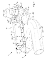
- Fig. 1
- eine perspektivische Ansicht auf eine Sauganlage nach der Erfindung,
- Fig. 2
- eine perspektivische Ansicht wie in Fig. 1, jedoch aus einer anderen Blickrichtung,
- Fig. 3
- einen perspektivischen Querschnitt durch die Sauganlage entsprechend den Schnittlinien III in den Fig. 1 und 2,
- Fig. 4
- einen Querschnitt durch die Sauganlage entsprechend den Schnittlinien IV in den Fig. 1 und 2,
- Fig. 5
- einen perspektivischen Längsschnitt durch die Sauanlage entsprechend den Schnittlinien V in den Fig. 1 und 2, jedoch bei einer vereinfachten Darstellung,
- Fig. 6
- eine stark vereinfachte geschnittene Draufsicht auf einen Teil der Sauganlage bei einer anderen Ausführungsform,
- Fig. 7
- eine Ansicht wie in Fig. 6, jedoch bei einer weiteren Ausführungsform.
- Entsprechend den Fig. 1 und 2 umfasst eine erfindungsgemäße Sauganlage 1 zumindest einen Frischgasverteiler 2, der mehreren Zylindern einer hier nicht gezeigten Brennkraftmaschine zugeordnet ist, die insbesondere in einem Kraftfahrzeug angeordnet sein kann. Der Frischgasverteiler 2 ist eingangsseitig mit einem Zuführungsrohr 3 verbunden, das von der Brennkraftmaschine angesaugte oder durch einen Lader angetriebene Frischluft dem Frischgasverteiler 2 zuführt. Bei der hier gezeigten Ausführungsform bildet ein Teil des Zuführungsrohrs 3 einen integralen Bestandteil des Frischgasverteilers 2. Im Frischgasverteiler 2 erfolgt nun die Aufteilung des zugeführten Frischgases auf die dem Frischgasverteiler 2 zugeordneten Zylinder.
- Zu diesem Zweck besitzt der Frischgasverteiler 2 für jeden ihm zugeordneten Zylinder zumindest einen Frischgasaustritt 4. Im vorliegenden Fall besitzt der Frischgasverteiler 2 für jeden Zylinder zwei Frischgasaustritte, nämlich jeweils einen Hauptaustritt 4a und einen Nebenaustritt 4b. Hierbei handelt es sich um eine spezielle Ausführungsform, die mit einer Schichtladetechnik, z.B. in Verbindung mit einer Drall- und/oder Tumbleströmung, arbeitet.
- Der hier gezeigte Frischgasverteiler 2 ist somit vier Zylindern zugeordnet, die in Reihe angeordnet sind. Sofern die Brennkraftmaschine ein Vier-Zylinder-Motor ist, kommt die Sauganlage 1 mit dem gezeigten Frischgasverteiler 2 aus. Sofern es sich bei der Brennkraftmaschine jedoch um einen V8-Motor handelt, der je vier Zylinder in zwei Zylinderbänken besitzt, ist der hier gezeigte Frischgasverteiler 2 der einen Zylinderbank zugeordnet, so dass die Sauganlage 1 noch einen weiteren, hier nicht gezeigten, im wesentlichen spiegelsymmetrisch aufgebauten Frischgasverteiler 2 aufweist.
- Die Frischgasaustritte 4 sind nebeneinander angeordnet und liegen im wesentlichen in einer Ebene. In dieser Ebene erfolgt auch die Anbindung des Frischgasverteilers 2 an den Motorblock der Brennkraftmaschine. Zu diesem Zweck ist der Frischgasverteiler 2 in der Ebene der Frischgasaustritte 4 mit einem Flansch 5 ausgestattet, der für jeden Zylinder einen Flanschabschnitt 6 mit jeweils zwei Durchgangsöffnungen 7 aufweist. Durch die Durchgangsöffnungen 7 kann jeder Flanschabschnitt 6 mit dem Motorblock oben und unten verschraubt werden. Auch der Flansch 5 ist zweckmäßig einstückig in den Frischgasverteiler 2 integriert.
- Den Fig. 1 und 2 sind außerdem wesentliche Bestandteile einer Abgasrückführungseinrichtung 8 entnehmbar, die insbesondere einen Abgaskühler 9, ein Schaltventil 10 und ein Abgasrückführungsventil 11, im folgenden AGR-Ventil 11, umfasst.
- Bezugnehmend auf die Fig. 3 bis 5 ist der Frischgasverteiler 2 außerdem mit einem Verteilerkanal 12 versehen, der zwar am Frischgasverteiler 2 angeordnet bzw. ausgebildet ist, jedoch zumindest funktional einen Bestandteil der AGR-Einrichtung 8 bildet. Erfindungsgemäß ist der Verteilerkanal 12 am Frischgasverteiler 2 so positioniert, dass er benachbart zu allen Frischgasaustritten 4 des Frischgasverteilers 2 angeordnet ist. Der lang gestreckt ausgestaltete Verteilerkanal 12 erstreckt sich dabei parallel zur Ebene der Frischgasaustritte 4. Die Anordnung des Verteilerkanals 12 erfolgt dabei so nah wie möglich an den Frischgasaustritten 4. Gemäß den Fig. 3 und 4 ist der Verteilerkanal 2 mit seiner Austrittsseite unmittelbar stromauf von Austrittstrichtern 13 angeordnet, die im Frischgasverteiler 2 ausgeformt sind, und jeweils zu einem Frischgasaustritt 4 bzw. zu einem Paar zusammengehöriger Austritte 4a und 4b konvergieren.
- Der Verteilerkanal 12 kommuniziert mit dem Frischgasverteiler 2. Zu diesem Zweck enthält der Verteilerkanal 12 an seiner Austrittsseite beispielsweise mehrere Rückführöffnungen 14, über die das Innere des Verteilerkanals 12 mit dem Inneren des Frischgasverteilers 2 strömungstechnisch verbunden ist. Bei der hier gezeigten bevorzugten Ausführungsform sind für die Kommunikation zwischen Verteilerkanal 12 und Frischgasverteiler 2 mehrere separate Rückführöffnungen 14 vorgesehen, die entlang des Verteilerkanals 12 zylinderselektiv positioniert ist. Das bedeutet, dass jede Rückführöffnung 14 unmittelbar stromauf des jeweils zugeordneten Frischgasaustritts 4 positioniert ist. Hierdurch ergibt sich ein möglichst kurzer Strömungsweg von der jeweiligen Rückführöffnung 14 bis zum jeweiligen Frischgasaustritt 4 und somit bis zum jeweiligen selektierten Zylinder. Im vorliegenden Fall sind je zwei Rückführöffnungen 14 je einem Zylinder zugeordnet. Die demselben Zylinder zugeordneten Rückführöffnungen 14 sind gemäß Fig. 3 beispielsweise mittig zum zugehörigen Austrittstrichter ausgerichtet.
- Da bei der hier gezeigten Ausführungsform jedem Zylinder ein Hauptaustritt 4a und ein Nebenaustritt 4b zugeordnet ist, kann die Positionierung der separat ausgestalteten Rückführöffnungen 14 bei einer besonderen Ausgestaltungsform der erfindungsgemäßen Sauganlage 1 außerdem hinsichtlich jeweils der Hauptaustritte 4a oder alternativ jeweils hinsichtlich der Nebenaustritte 4b selektiv erfolgen. Zweckmäßig ist die Positionierung dann jeweils im Hinblick auf einen möglichst kurzen Strömungsweg von der jeweiligen Rückführöffnung 14 bis zum jeweils selektierten Hauptaustritt 4a bzw. Nebenaustritt 4b optimiert. Beispielsweise sind die dem jeweiligen Austritt 4a, 4b zugeführten Rückführöffnungen 14 dann bezüglich des zugeordneten Austritts 4a, 4b mittig angeordnet.
- Die zylinderselektive bzw. die austrittselektive Positionierung der Rückführöffnungen 14 stellen jeweils besondere Ausführungsformen der vorliegenden Erfindung dar. Grundsätzlich kann die Austrittsseite des Verteilerkanals 12 auch so ausgestattet sein, dass sich über die gesamte Länge des Verteilerkanals 12 eine im wesentlichen gleichmäßige Abgasrückführung in den Abgasverteiler 2 ausbildet. Beispielsweise können die diskreten Rückführöffnungen 14 über die gesamte Länge des Verteilerkanals 12 gleichmäßig verteilt angeordnet sein. Anstelle einzelner Rückführöffnungen 14 in der Austrittsseite kann auch vorgesehen sein, die Austrittsseite durch eine poröse Wandung oder dgl. zu bilden.
- Entsprechend der hier gezeigten, bevorzugten Ausführungsform ist der Verteilerkanal 12 einstückig in den Frischgasverteiler 2 integriert, das heißt der Verteilerkanal 12 bildet einen integralen Bestandteil des Frischgasverteilers 2. Beispielsweise kann der Frischgasverteiler 2 zusammen mit dem Verteilerkanal 12 als integrales Gußteil, insbesondere aus Kunststoff oder aus Metall, ausgestaltet sein.
- Insbesondere im Hinblick auf die Fig. 3 und 4 ist entnehmbar, dass der Verteilerkanal 12 im Querschnitt ein U-Profil aufweist, das eine vom Inneren des Frischgasverteilers 2 weg gerichtete offene Seite 15 und eine dem Inneren des Frischgasverteilers 2 zugewandte U-Basis 16 aufweist. Durch die U-Basis 16 erfolgt die Kommunikation zwischen Verteilerkanal 12 und Frischgasverteiler 2. Im vorliegenden Fall bedeutet dies, dass die Rückführöffnungen 14 in der U-Basis 16 ausgebildet sind.
- Die offene Seite 15 des Verteilerkanals 12 ist hier mittels einer Deckelplatte 17 verschlossen. Die Deckelplatte 17 ist hier mit dem Frischgasverteiler 2 verschraubt, was durch Schrauben 18 angedeutet ist. Zu diesem Zweck sind an der Deckelplatte 17 seitlich vorstehende Augen 19 ausgebildet, die von den jeweiligen Schrauben 18 durchsetzt sind.
- Bezugnehmend auf Fig. 4 besitzt das Schaltventil 10 der AGR-Einrichtung 8 einen Eingang 20 und zwei Ausgänge, nämlich einen ersten Ausgang 21 und einen zweiten Ausgang 22. Der Eingang 20 ist hier unmittelbar an eine Ausgangsseite 23 des AGR-Ventils 11 angeschlossen, dessen Eingangsseite 24 an eine hier nicht gezeigte Abgaszuführungsleitung der AGR-Einrichtung 8 angeschlossen ist, die ihrerseits zur Abgasentnahmestelle am Abgastrakt der Brennkraftmaschine führt. Insoweit ist der Eingang 20 indirekt an die Abgaszuführungsleitung angeschlossen, in der das AGR-Ventil 11 angeordnet ist.
- Der erste Ausgang 21 des Schaltventils 10 ist hier unmittelbar an den Verteilerkanal 12 angeschlossen, und zwar durch die Deckelplatte 17 hindurch. Bei der hier gezeigten, bevorzugten Ausführungsform ist die Deckelplatte 17 zusammen mit einem Gehäuse 25 des Schaltventils 10 einstückig hergestellt, das heißt die Deckelplatte 17 ist in das Gehäuse 25 integriert. Beispielsweise ist das Gehäuse 25 zusammen mit der Deckelplatte 17 als Gussbauteil, insbesondere aus Kunststoff oder Metall hergestellt.
- Der zweite Ausgang 22 des Schaltventils 10 ist an einen Abgaseinlaß 26 des Abgaskühlers 9 angeschlossen. Ein Abgasauslaß 27 des Abgaskühlers 9 ist durch die Deckelplatte 17 hindurch ebenfalls an den Verteilerkanal 12 angeschlossen. Im Innern des Abgaskühlers 9 führt ein Abgaspfad vom Abgaseinlaß 26 zum Abgasauslaß 27.
- Das Schaltventil 10 kann nun wenigstens zwischen zwei Schaltstellungen geschaltet werden. In der in Fig. 4 gezeigten ersten Endstellung befindet sich ein Ventilkörper 28 des Schaltventils 10 in einem Ventilsitz 29, der im Bereich des ersten Ausgangs 21 angeordnet ist, so dass in dieser ersten Endstellung der erste Ausgang 21 verschlossen ist, während der zweite Ausgang 22 offen ist. Dementsprechend ist im Schaltventil 10 in einer ersten Schaltstellung der Eingang 20 mit dem zweiten Ausgang 22 verbunden, so dass die über das AGR-Ventil 11 zugeführten Abgase den Abgaskühler 9 durchströmen und über dessen Abgasauslaß 27 in den Verteilerkanal 12 eintreten. Hierdurch werden die rückgeführten Abgase vor ihrem Eintritt in den Frischgasverteiler 2 gekühlt. Eine Abgaskühlung kann im Hinblick auf das Verbrennungsverhalten und die Leistungsentfaltung der Brennkraftmaschine von Vorteil sein.
- Bei bestimmten Betriebszuständen der Brennkraftmaschine, insbesondere beim Kaltstart, ist es jedoch von Vorteil, wenn die rückgeführten Abgase ungekühlt zum Frischgasverteiler 2 gelangen. Zu diesem Zweck besitzt das Schaltventil 10 eine zweite Schaltstellung, in welcher der Ventilkörper 28 von seinem Sitz 29 mehr oder weniger abgehoben ist und somit den ersten Ausgang 21 freigibt. In der nicht gezeigten, zweiten Schaltstellung kann der Ventilkörper 28 die Verbindung zwischen Eingang und zweitem Ausgang 22 sperren. Bei einem hinreichenden Strömungswiderstand im Abgaspfad des Abgaskühlers 9 ist eine derartige Sperrung der Verbindung zwischen Eingang 20 und zweitem Ausgang 22 in der Regel nicht erforderlich, da die Abgasströmung von selbst den Weg des geringsten Widerstands geht, so dass die Durchströmung des Abgaskühlers 9 bei geöffnetem ersten Ausgang 21 erheblich oder vollständig zurückgeht.
- In der zweiten Schaltstellung strömen die rückgeführten Abgase somit vom Eingang 20 zum ersten Ausgang 21 und somit auf kurzem Wege vom AGR-Ventil 11 zum Verteilerkanal 12. Die rückgeführten Abgase sind dann ungekühlt und können so der Brennkraftmaschine zusätzlich Wärme zuführen. Dies kann auch bei größeren Dieselmotoren nach dem Warmlaufen erforderlich sein, wenn diese im Teillastbetrieb aufgrund ihres günstigen Wirkungsgrades zu wenig Wärme erzeugen.
- Grundsätzlich kann es für bestimmte Betriebszustände der Brennkraftmaschine auch wünschenswert sein, nur einen Teil der rückgeführten Abgase zu kühlen, um dadurch eine gewisse Mischtemperatur zu erzeugen. Das jeweilige Schaltventil 10 kann dann zum Einstellen wenigstens einer zusätzlichen Zwischenstellung ausgestaltet sein, in der die Abgase vom Eingang 20 sowohl durch den ersten Ausgang 21 als auch durch den zweiten Ausgang 22 geführt werden.
- Die hier gezeigte, besondere Ausführungsform zeichnet sich auch dadurch aus, dass der erste Ausgang 21 des Schaltventils 10 und der Abgasauslaß 27 des Abgaskühlers 9 separat und voneinander beabstandet an den Verteilerkanal 12 angeschlossen sind, was den Aufbau der Sauganlage 1 vereinfacht. Von besonderer Bedeutung ist hier das Merkmal, wonach ein besonders großer Abstand zwischen den beiden Einleitstellen in den Verteilerkanal 12, also zwischen erstem Ausgang 21 und Abgasauslaß 27 ausgebildet ist. Beispielhaft sind hier erster Ausgang 21 und Abgasauslaß 27 an voneinander entfernten Enden des Verteilerkanals 12 angeordnet. Diese Anordnung ermöglicht für den Abgaskühler 9 eine langgestreckte Bauweise, wodurch die Sauganlage 1 besonders kompakt baut.
- Der Abgaskühler 9 ist im Bereich seines Abgaseinlasses 26 über eine entsprechende Flanschverbindung 30 am Gehäuse 25 des Schaltventils 10 befestigt. Im Bereich seines Abgasauslasses 27 ist der Abgaskühler 9 über die Deckelplatte 17 bzw. mit deren Schrauben 18 am Abgasverteiler 2 befestigt. Die Verbindung zwischen Abgaskühler 9 einerseits und Schaltventil 10 und Deckelplatte 17 andererseits ist dabei gezielt so ausgestaltet, dass sich zwischen der dem Abgaskühler 9 zugewandten Oberseite der Deckelplatte 17 und der der Deckelplatte 17 zugewandten untersten Seite des Abgaskühlers 9 ein Abstand 31 einstellt, der so bemessen ist, dass durch diesen Abstand 31 hindurch die oberen Durchgangsöffnungen 7 der beiden mittleren Flanschabschnitte 6 zugänglich sind, was die Montage des Frischgasverteilers 2 an der Brennkraftmaschine erheblich vereinfacht, wenn die zugehörigen Komponenten der AGR-Einrichtung 8 bereits am Frischgasverteiler 2 montiert. Somit kann die Sauganlage 1 zumindest im Bereich des Frischgasverteilers 2 bereits vollständig vormontiert und hinsichtlich ihrer Funktion überprüft werden, bevor sie als Einheit an die Brennkraftmaschine angebaut wird.
- Des Weiteren bilden auch mehrere Komponenten der AGR-Einrichtung 8 eine vormontierbare Einheit 32. Diese Einheit 32 umfasst zumindest die Deckelplatte 17, das Schaltventil 10 und den Abgaskühler 9. Optional umfasst die Einheit 32 auch das AGR-Ventil 11. Diese Einheit 32 ist unabhängig vom Frischgasverteiler 2 vormontierbar und kann komplett montiert über die Deckelplatte 17 am Frischgasverteiler 2 montiert werden. Die Ausbildung dieser Einheit 32 vereinfacht den Zusammenbau der Sauganlage 1 und die unabhängige Funktionsüberprüfung der AGR-Komponenten.
- Im Abgaskühler 9 ist der Abgaspfad wärmeübertragend mit einem Kühlmittelpfad gekoppelt, der an einen entsprechenden Kühlmittelkreis, insbesondere an den Kühlkreis der Brennkraftmaschine, angeschlossen werden kann. Zu diesem Zweck sind am Abgaskühler 9 zwei Kühlmittelanschlüsse, nämlich ein erster Kühlmittelanschluß 33 und ein zweiter Kühlmittelanschluß 34 ausgebildet. Eine Besonderheit ist hier, dass auch das AGR-Ventil 11 aktiv gekühlt ist. Zu diesem Zweck ist in einem Gehäuse 35 des AGR-Ventils 11 ein entsprechender Kühlmittelpfad ausgebildet. Des Weiteren weist das Gehäuse 35 des AGR-Ventils 11 zwei Kühlmittelanschlüsse, nämlich einen dritten Kühlmittelanschluß 36 und einen vierten Kühlmittelanschluß 37 auf. Gemäß den Fig. 1 und 3 sind die Kühlmittelanschlüsse 33, 34, 36, 37 hier so aufeinander abgestimmt, dass in montiertem Zustand der eine Kühlmittelanschluß (zweiter Kühlmittelanschluß 34) des Abgaskühlers 9 direkt mit dem einen Kühlmittelanschluß (dritter Kühlmittelanschluß 36) des AGR-Ventils 11 verbunden ist, so dass auf zusätzliche Verbindungsstücke verzichtet werden kann.
- Während bei den mit Bezug auf die Fig. 1 bis 5 erläuterten Ausführungsformen nur ein einziger Verteilerkanal 12 vorgesehen ist, an den sowohl der erste Ausgang 21 des Schaltventils 10 als auch der Abgasauslaß 27 des Abgaskühlers 9 angeschlossen sind, zeigen die Fig. 6 und 7 diesbezüglich andere Ausführungsformen, die jedoch im Hinblick auf die anderen Merkmale im wesentlichen identisch zu den zuvor beschriebenen Ausführungsformen aufgebaut sein können.
- Bei der Ausführungsform gemäß Fig. 6 sind zwei Verteilerkanäle 12 und 12' vorgesehen, die jeweils benachbart zu allen Frischgasaustritten 4 angeordnet sind, wobei sie sich jeweils in unmittelbarer Nähe der Frischgasaustritte 4 befinden. Die beiden Verteilerkanäle 12, 12' erstrecken sich dabei parallel zueinander. Jeder Verteilerkanal 12, 12' kommuniziert mit dem Frischgasverteiler 2, wobei die Verteilerkanäle 12, 12` hier jeweils mit den diskreten Rückführöffnungen 14 ausgestattet sind, und zwar für jeden Frischgasaustritt 4 jeweils eine Rückführöffnung 14. Eine Besonderheit wird nun darin gesehen, dass der erste Ausgang 21 an den einen Verteilerkanal 12 angeschlossen ist, während der Abgasauslaß 27 an den anderen Verteilerkanal 12' angeschlossen ist. Demzufolge wird über den einen Verteilerkanal 12 ausschließlich ungekühltes Abgas in den Frischgasverteiler 2 eingeleitet, während über den anderen Verteilerkanal 12' ausschließlich gekühltes Abgas in den Frischgasverteiler 2 eingeleitet wird. Dies ist insbesondere bei einem Mischbetrieb von Vorteil, bei dem das Schaltventil 10 so angesteuert wird, dass ein mehr oder weniger großer erster Teilstrom des rückgeführten Abgases ungekühlt durch den ersten Ausgang 21 in den einen Verteilerkanal 12 gelangt, während ein verbleibender zweiter Teilstrom des rückgeführten Abgases durch den Abgaskühler 9 geführt wird und durch dessen Abgasauslaß 27 in den anderen Verteilerkanal 12 gelangt. Durch die getrennte Führung der gekühlten und der ungekühlten Abgase kommt es erst im Frischgasverteiler 2 unmittelbar stromauf der Frischgasaustritte 4 zu einer Vermischung der gekühlten und der ungekühlten Abgase mit dem Frischgas (Frischluft), wodurch eine gewünschte Mischtemperatur an allen Frischgasaustritten 4 relativ gleichmäßig eingestellt werden kann. Bei einer gleichzeitigen Einleitung gekühlter und ungekühlter rückgeführter Abgase in den selben Verteilerkanal 12, was beispielsweise bei der Variante gemäß den Fig. 1 bis 5 möglich wäre, würde sich bei den durch die Rückführöffnungen 14 in den Frischgasverteiler 2 einströmenden Abgasen ein Temperaturgefälle vom ersten Ausgang 21 bis zum Abgasauslaß 27 einstellen. Die Temperaturverteilung auf die einzelnen Frischgasaustritte 4 und somit auf die einzelnen Zylinder wäre dann ungleichmäßig.
- Bei der Variante gemäß Fig. 7 kann ebenfalls eine simultane und dabei getrennte Zuführung gekühlter und ungekühlter Abgase in den Frischgasverteiler 2 realisiert werden, ohne dass dazu zwei getrennte Verteilerkanäle 12 und 12' wie bei der Ausführungsform gemäß Fig. 6 erforderlich sind. Zu diesem Zweck ist der einzige Verteilerkanal 12 mittels einer Trennwand 38 in zwei voneinander getrennte Verteilerteilkanäle 12a und 12b geteilt. Jeder dieser Verteilerteilkanäle 12a, 12b erstreckt wieder benachbart zu allen Frischgasaustritten 4 und kommuniziert vorzugsweise über diskrete Rückführungöffnung 14 mit dem Frischgasverteiler 12. Analog zur Variante gemäß Fig. 6 ist der eine Verteilerteilkanal 12a an den ersten Ausgang 21 des Schaltventils 10 angeschlossen, während der andere Verteilerteilkanal 12b an den Abgasauslaß 27 des Abgaskühlers 9 angeschlossen ist.
Claims (11)
- Sauganlage für eine Brennkraftmaschine, insbesondere in einem Kraftfahrzeug, mit wenigstens einem Frischgasverteiler (2), der zur Zuführung von Frischgas zu mehreren dem Frischgasverteiler (2) zugeordneten Zylindern der Brennkraftmaschine dient und für jeden zugeordneten Zylinder zumindest einen Frischgasaustritt (4, 4a, 4b) aufweist, die nebeneinander angeordnet sind, wobei am Frischgasverteiler (2) zumindest ein Verteilerkanal (12) einer Abgasrückführungseinrichtung (8) vorgesehen ist, der benachbart zu allen Frischgasaustritten (4, 4a, 4b) des Frischgasverteilers (2) angeordnet ist und mit dem Frischgasverteiler (2) kommuniziert,
dadurch gekennzeichnet- dass die Abgasrückführungseinrichtung (8) ein Schaltventil (10) mit einem Eingang (20) und zwei Ausgängen (21, 22) aufweist,- dass der Eingang (20) des Schaltventils (10) an ein Abgasrückführventil (11) oder an eine Abgaszuführungsleitung der Abgasrückführungseinrichtung (8) angeschlossen ist,- dass der erste Ausgang (21) des Schaltventils (10) an den Verteilerkanal (12) angeschlossen ist,- dass der zweite Ausgang (22) des Schaltventils (10) an einen Abgaseinlass (26) eines Abgaskühlers (9) der Abgasrückführungseinrichtung (8) angeschlossen ist,- dass ein Abgasauslass (27) des Abgaskühlers (9) separat und beabstandet vom ersten Ausgang (21) des Schaltventils (10) an den selben oder an einen anderen Verteilerkanal (12) angeschlossen ist. - Sauganlage nach Anspruch 1,
dadurch gekennzeichnet,
dass der Verteilerkanal (12) in den Frischgasverteiler (2) einstückig integriert ist. - Sauganlage nach Anspruch 1 oder 2,
dadurch gekennzeichnet,
dass der Verteilerkanal (12) ein U-Profil aufweist, dessen offene Seite (15) vom Inneren des Frischgasverteilers (2) weggerichtet ist und durch dessen U-Basis (16) der Verteilerkanal (12) mit dem Frischgasverteiler (2) kommuniziert. - Sauganlage nach Anspruch 3,
dadurch gekennzeichnet,
dass der Verteilerkanal (12) an der offenen Seite (15) seines Profils mit einer Deckelplatte (17) verschlossen ist, durch die durch den Verteilerkanal (12) im Betrieb der Abgasrückführungseinrichtung (8) Abgas zuführbar ist. - Sauganlage nach Anspruch 4,
dadurch gekennzeichnet,
dass die Deckelplatte (17) in ein Gehäuse (25) des Schaltventils (10) einstückig integriert ist - Sauganlage nach Anspruch 5,
dadurch gekennzeichnet,
dass der Abgaskühler (9) und das Schaltventil (10) mit Gehäuse (25) und Deckelplatte (17) eine vormontierbare Einheit (32) bilden, die über die Deckelplatte (17) am Frischgasverteiler (2) montierbar ist. - Sauganlage nach einem der Ansprüche 1 bis 6,
dadurch gekennzeichnet,
dass der Verteilerkanal (12) durch mehrere separate Rückführöffnungen (14) mit dem Frischgasverteiler (2) kommuniziert, wobei die Rückführöffnungen (14) entlang des Verteilerkanals (12) bezüglich der dem Frischgasverteiler (2) zugeordneten Zylinder selektiv positioniert sind. - Sauganlage nach Anspruch 7,
dadurch gekennzeichnet,
dass der Frischgasverteiler (2) für jeden zugeordneten Zylinder zwei nebeneinander angeordnete Frischgasaustritte (4) aufweist, nämlich jeweils einen Hauptaustritt (4a) und einen Nebenaustritt (4b), wobei die Rückführöffnungen (14) entlang des Verteilerkanals (12) bezüglich der Hauptaustritte (4a) oder der Nebenaustritte (4b) selektiv positioniert sind. - Sauganlage nach einem der Ansprüche 1 bis 8,
dadurch gekennzeichnet,
dass der Abgasauslass (27) des Abgaskühlers (9) und der erste Ausgang (21) des Schaltventiles (10) an voneinander entfernten Enden an den Verteilerkanal (12) angeschlossen sind. - Sauganlage nach einem der Ansprüche 1 bis 9,
dadurch gekennzeichnet,
dass zwei getrennte Verteilerkanäle (12, 12') vorgesehen sind, wobei der erste Ausgang (21) des Schaltventils (10) an den einen Verteilerkanal (12) angeschlossen ist, während der Abgasauslass (27) des Abgaskühlers (9) an den anderen Verteilerkanal (12') angeschlossen ist. - Sauganlage nach einem der Ansprüche 1 bis 9,
dadurch gekennzeichnet,
dass im Verteilerkanal (12) zwei voneinander getrennte Verteilerkanäle (12a, 12b) ausgebildet sind, die jeweils benachbart zu allen Frischgasaustritten (4, 4a, 4b) angeordnet sind und von denen der eine Verteilerkanal (12a) an den ersten Ausgang (21) des Schaltventils (10) angeschlossen ist, während der andere Verteilerkanal (12b) an den Abgasauslass (27) des Abgaskühlers (9) angeschlossen ist.
Applications Claiming Priority (2)
| Application Number | Priority Date | Filing Date | Title |
|---|---|---|---|
| DE10354129A DE10354129A1 (de) | 2003-11-19 | 2003-11-19 | Sauganlage für eine Brennkraftmaschine |
| EP04026887A EP1533512B1 (de) | 2003-11-19 | 2004-11-12 | Sauganlage für eine Brennkraftmaschine |
Related Parent Applications (1)
| Application Number | Title | Priority Date | Filing Date |
|---|---|---|---|
| EP04026887A Division EP1533512B1 (de) | 2003-11-19 | 2004-11-12 | Sauganlage für eine Brennkraftmaschine |
Publications (3)
| Publication Number | Publication Date |
|---|---|
| EP1870591A2 true EP1870591A2 (de) | 2007-12-26 |
| EP1870591A3 EP1870591A3 (de) | 2008-02-20 |
| EP1870591B1 EP1870591B1 (de) | 2009-07-29 |
Family
ID=34428809
Family Applications (2)
| Application Number | Title | Priority Date | Filing Date |
|---|---|---|---|
| EP04026887A Ceased EP1533512B1 (de) | 2003-11-19 | 2004-11-12 | Sauganlage für eine Brennkraftmaschine |
| EP07118191A Ceased EP1870591B1 (de) | 2003-11-19 | 2004-11-12 | Sauganlage für eine Brennkraftmaschine |
Family Applications Before (1)
| Application Number | Title | Priority Date | Filing Date |
|---|---|---|---|
| EP04026887A Ceased EP1533512B1 (de) | 2003-11-19 | 2004-11-12 | Sauganlage für eine Brennkraftmaschine |
Country Status (2)
| Country | Link |
|---|---|
| EP (2) | EP1533512B1 (de) |
| DE (3) | DE10354129A1 (de) |
Cited By (8)
| Publication number | Priority date | Publication date | Assignee | Title |
|---|---|---|---|---|
| US20100199663A1 (en) * | 2009-02-12 | 2010-08-12 | Mann+Hummel Gmbh | Exhaust Gas Inlet Device |
| FR2945582A1 (fr) * | 2009-05-18 | 2010-11-19 | Mann & Hummel Gmbh | Dispositif de recirculation des gaz d'echappement d'un moteur a combustion interne |
| FR2946699A1 (fr) * | 2009-06-15 | 2010-12-17 | Valeo Systemes Thermiques | Dispositif de melange d'un flux de gaz d'admission et d'un flux de gaz d'echappement recircules comprenant des moyens d'injection de gaz recircules |
| FR2954414A1 (fr) * | 2009-12-21 | 2011-06-24 | Valeo Systemes Thermiques | Piece d'interface entre une culasse d'un moteur de vehicule automobile et un echangeur de chaleur. |
| FR2954413A1 (fr) * | 2009-12-21 | 2011-06-24 | Valeo Systemes Thermiques | Module d'alimentation en gaz d'un moteur de vehicule automobile, ensemble d'une culasse d'un moteur et d'un tel module et moteur thermique comportant un tel ensemble. |
| CN102317611A (zh) * | 2009-02-16 | 2012-01-11 | 卡特彼勒发动机有限及两合公司 | 带有排气再循环的涡轮增压发动机 |
| WO2012130513A1 (fr) * | 2011-03-31 | 2012-10-04 | Valeo Systemes Thermiques | Dispositif d'injection de gaz d'echappement recircules, boitier repartiteur et module d'alimentation comprenant ledit dispositif |
| EP2525075A1 (de) * | 2011-04-28 | 2012-11-21 | VALEO AUTOSYSTEMY Sp. Z. o.o. | Injektionskanalumgehung für Sondenmessung |
Families Citing this family (20)
| Publication number | Priority date | Publication date | Assignee | Title |
|---|---|---|---|---|
| FR2870893B1 (fr) * | 2004-05-25 | 2008-08-08 | Mark Iv Systemes Moteurs Sa | Module d'admission d'air integre et son procede de fabrication |
| FR2891020B1 (fr) * | 2005-09-16 | 2007-11-23 | Renault Sas | Repartiteur d'admission integrant une partie d'un circuit de recirculation des gaz d'echappement et moteur a combustion interne comprenant un tel repartiteur d'admission |
| FR2894295B1 (fr) | 2005-12-01 | 2010-04-30 | Mark Iv Systemes Moteurs Sa | Module multifonctionnel pour moteur a combustion interne |
| FR2908833B1 (fr) * | 2006-11-20 | 2011-06-17 | Valeo Sys Controle Moteur Sas | Dispositif d'admission de gaz |
| CN101646849B (zh) * | 2007-03-23 | 2011-10-05 | 贝洱两合公司 | 增压流体吸入模块和内燃机 |
| ES2299405B1 (es) * | 2007-10-09 | 2009-09-11 | Dayco Ensa S.L. | Modulo integrado egr/refrigeracion para un motor de combustion interna. |
| FR2931517B1 (fr) * | 2008-05-20 | 2012-09-21 | Valeo Sys Controle Moteur Sas | Dispositif d'admission de gaz |
| EP2133548B1 (de) | 2008-06-12 | 2019-06-12 | Perkins Engines Company Limited | Gasmischsystem |
| WO2009149868A1 (en) * | 2008-06-12 | 2009-12-17 | Perkins Engines Company Limited | Exhaust gas mixing system |
| DE102008063934A1 (de) | 2008-12-19 | 2010-06-24 | Volkswagen Ag | Brennkraftmaschine mit Abgasrückführung |
| FR2953255B1 (fr) * | 2009-11-27 | 2012-10-12 | Valeo Systemes Thermiques | Module d'alimentation en gaz d'un moteur de vehicule automobile, ensemble d'une culasse d'un moteur et d'un tel module, et moteur de vehicule automobile comportant un tel ensemble |
| FR2958336B1 (fr) | 2010-03-31 | 2013-03-15 | Valeo Systemes Thermiques | Collecteur de repartition de gaz dans la culasse d'un moteur avec melange des gaz d'echappement recircules a contre-courant des gaz d'admission. |
| FR2958337B1 (fr) | 2010-03-31 | 2013-03-01 | Valeo Systemes Thermiques | Collecteur de repartition de gaz dans la culasse d'un moteur, ensemble d'un collecteur de repartition et d'une culasse de moteur. |
| NL2005133C2 (nl) * | 2010-07-23 | 2012-01-24 | Daf Trucks Nv | Inrichting voor het mengen van terug te voeren uitlaatgas met verse lucht voor een verbrandingsmotor. |
| DE102010051562B4 (de) * | 2010-11-18 | 2014-05-08 | Pierburg Gmbh | Abgasführungsvorrichtung für eine Verbrennungskraftmaschine |
| DE102011014541B4 (de) * | 2011-03-19 | 2019-01-17 | Audi Ag | Luftzufuhrelement für eine Verbrennungskraftmaschine und Verfahren zum Fertigen eines Luftzufuhrelements |
| FR2973445B1 (fr) * | 2011-03-31 | 2015-08-21 | Valeo Systemes Thermiques | Boitier repartiteur de gaz d'admission dans un moteur, notamment de vehicule automobile, et module d'alimentation en gaz comprenant ledit boitier |
| FR3007470B1 (fr) | 2013-06-25 | 2017-08-11 | Valeo Systemes De Controle Moteur | Module de distribution pour distribuer un melange d’admission |
| DE102013215234A1 (de) | 2013-08-02 | 2015-02-05 | Mahle International Gmbh | Ansaugmodul für eine Brennkraftmaschine |
| DE102014214591A1 (de) | 2014-07-24 | 2016-01-28 | Mahle International Gmbh | Ansaugmodul mit integrierter Abgasrückführung für eine Brennkraftmaschine |
Citations (13)
| Publication number | Priority date | Publication date | Assignee | Title |
|---|---|---|---|---|
| US4715329A (en) * | 1985-04-09 | 1987-12-29 | Nissan Motor Co., Ltd. | Induction system for internal combustion engine |
| JPH04279754A (ja) * | 1991-03-08 | 1992-10-05 | Toyota Autom Loom Works Ltd | Egrガスデポジット低減マニホルド |
| EP0565410A1 (de) * | 1992-04-09 | 1993-10-13 | Automobiles Peugeot | Integrierte Rampenvorrichtung für die Abgasrückführung einer Brennkraftmaschine |
| JPH08144868A (ja) * | 1994-11-17 | 1996-06-04 | Toyota Motor Corp | 内燃機関の排気ガス再循環装置 |
| JPH1182197A (ja) * | 1997-09-08 | 1999-03-26 | Denso Corp | 内燃機関の吸気装置 |
| US5957116A (en) * | 1997-08-28 | 1999-09-28 | Cummins Engine Company, Inc. | Integrated and separable EGR distribution manifold |
| EP1122421A2 (de) * | 2000-02-02 | 2001-08-08 | Filterwerk Mann + Hummel Gmbh | Saugrohr mit integrierter Abgasrückführung |
| EP1152131A1 (de) * | 2000-05-05 | 2001-11-07 | Volvo Personvagnar AB | Verfahren und Vorrichtung zur Abgasentlüftung einer Brennkraftmaschine |
| DE10028131C1 (de) * | 2000-06-07 | 2001-12-13 | Daimler Chrysler Ag | Abgasrückführsystem für eine Brennkraftmaschine |
| EP1164280A2 (de) * | 2000-06-13 | 2001-12-19 | Pierburg Aktiengesellschaft | Luftansaugvorrichtung für eine Brennkraftmaschine |
| EP1273786A2 (de) * | 2001-07-07 | 2003-01-08 | Pierburg GmbH | Umschalteinrichtung zur Abgasrückführung bei einer Brennkraftmaschine |
| EP1319825A1 (de) * | 2001-12-14 | 2003-06-18 | MAGNETI MARELLI POWERTRAIN S.p.A. | Ansaugkrümmer mit Abgasrückführung für Brennkraftmaschinen |
| WO2005024220A1 (de) * | 2003-09-05 | 2005-03-17 | Pierburg Gmbh | Luftansaugkanalsystem für eine verbrennungskraftmaschine |
Family Cites Families (4)
| Publication number | Priority date | Publication date | Assignee | Title |
|---|---|---|---|---|
| JPH06288305A (ja) * | 1993-03-31 | 1994-10-11 | Suzuki Motor Corp | エンジンの排気ガス再循環装置 |
| AT3671U1 (de) * | 1997-01-23 | 2000-06-26 | Avl List Gmbh | Brennkraftmaschine mit innerer verbrennung |
| DE19833325A1 (de) * | 1998-07-24 | 2000-01-27 | Opel Adam Ag | Hubkolben-Brennkraftmaschine mit Abgasrückführung |
| DE19906401C1 (de) * | 1999-02-16 | 2000-08-31 | Ranco Inc Of Delaware Wilmingt | Abgasrückführsystem |
-
2003
- 2003-11-19 DE DE10354129A patent/DE10354129A1/de not_active Withdrawn
-
2004
- 2004-11-12 EP EP04026887A patent/EP1533512B1/de not_active Ceased
- 2004-11-12 DE DE502004009844T patent/DE502004009844D1/de active Active
- 2004-11-12 EP EP07118191A patent/EP1870591B1/de not_active Ceased
- 2004-11-12 DE DE502004006651T patent/DE502004006651D1/de active Active
Patent Citations (13)
| Publication number | Priority date | Publication date | Assignee | Title |
|---|---|---|---|---|
| US4715329A (en) * | 1985-04-09 | 1987-12-29 | Nissan Motor Co., Ltd. | Induction system for internal combustion engine |
| JPH04279754A (ja) * | 1991-03-08 | 1992-10-05 | Toyota Autom Loom Works Ltd | Egrガスデポジット低減マニホルド |
| EP0565410A1 (de) * | 1992-04-09 | 1993-10-13 | Automobiles Peugeot | Integrierte Rampenvorrichtung für die Abgasrückführung einer Brennkraftmaschine |
| JPH08144868A (ja) * | 1994-11-17 | 1996-06-04 | Toyota Motor Corp | 内燃機関の排気ガス再循環装置 |
| US5957116A (en) * | 1997-08-28 | 1999-09-28 | Cummins Engine Company, Inc. | Integrated and separable EGR distribution manifold |
| JPH1182197A (ja) * | 1997-09-08 | 1999-03-26 | Denso Corp | 内燃機関の吸気装置 |
| EP1122421A2 (de) * | 2000-02-02 | 2001-08-08 | Filterwerk Mann + Hummel Gmbh | Saugrohr mit integrierter Abgasrückführung |
| EP1152131A1 (de) * | 2000-05-05 | 2001-11-07 | Volvo Personvagnar AB | Verfahren und Vorrichtung zur Abgasentlüftung einer Brennkraftmaschine |
| DE10028131C1 (de) * | 2000-06-07 | 2001-12-13 | Daimler Chrysler Ag | Abgasrückführsystem für eine Brennkraftmaschine |
| EP1164280A2 (de) * | 2000-06-13 | 2001-12-19 | Pierburg Aktiengesellschaft | Luftansaugvorrichtung für eine Brennkraftmaschine |
| EP1273786A2 (de) * | 2001-07-07 | 2003-01-08 | Pierburg GmbH | Umschalteinrichtung zur Abgasrückführung bei einer Brennkraftmaschine |
| EP1319825A1 (de) * | 2001-12-14 | 2003-06-18 | MAGNETI MARELLI POWERTRAIN S.p.A. | Ansaugkrümmer mit Abgasrückführung für Brennkraftmaschinen |
| WO2005024220A1 (de) * | 2003-09-05 | 2005-03-17 | Pierburg Gmbh | Luftansaugkanalsystem für eine verbrennungskraftmaschine |
Cited By (17)
| Publication number | Priority date | Publication date | Assignee | Title |
|---|---|---|---|---|
| US8677982B2 (en) * | 2009-02-12 | 2014-03-25 | Mann+Hummel Gmbh | Exhaust gas inlet device |
| US20100199663A1 (en) * | 2009-02-12 | 2010-08-12 | Mann+Hummel Gmbh | Exhaust Gas Inlet Device |
| CN102317611A (zh) * | 2009-02-16 | 2012-01-11 | 卡特彼勒发动机有限及两合公司 | 带有排气再循环的涡轮增压发动机 |
| FR2945582A1 (fr) * | 2009-05-18 | 2010-11-19 | Mann & Hummel Gmbh | Dispositif de recirculation des gaz d'echappement d'un moteur a combustion interne |
| US8584656B2 (en) | 2009-05-18 | 2013-11-19 | Mann+Hummel Gmbh | Self-cooling exhaust gas recirculation device for an internal combustion engine |
| FR2946699A1 (fr) * | 2009-06-15 | 2010-12-17 | Valeo Systemes Thermiques | Dispositif de melange d'un flux de gaz d'admission et d'un flux de gaz d'echappement recircules comprenant des moyens d'injection de gaz recircules |
| FR2954413A1 (fr) * | 2009-12-21 | 2011-06-24 | Valeo Systemes Thermiques | Module d'alimentation en gaz d'un moteur de vehicule automobile, ensemble d'une culasse d'un moteur et d'un tel module et moteur thermique comportant un tel ensemble. |
| WO2011076539A1 (fr) * | 2009-12-21 | 2011-06-30 | Valeo Systemes Thermiques | Piece d'interface entre une culasse d'un moteur de vehicule automobile et un echangeur de chaleur |
| WO2011076538A1 (fr) * | 2009-12-21 | 2011-06-30 | Valeo Systemes Thermiques | Module d'alimentation en gaz d'un moteur de vehicule automobile, ensemble d'une culasse d'un moteur et d'un tel module et moteur thermique comportant un tel ensemble |
| FR2954414A1 (fr) * | 2009-12-21 | 2011-06-24 | Valeo Systemes Thermiques | Piece d'interface entre une culasse d'un moteur de vehicule automobile et un echangeur de chaleur. |
| US9394862B2 (en) | 2009-12-21 | 2016-07-19 | Valeo Systemes Thermiques | Interface part between a motor vehicle engine head and a heat exchanger |
| EP2516822B1 (de) | 2009-12-21 | 2018-02-14 | Valeo Systèmes Thermiques | Einlassmodul eines Kraftfahrzeugs mit einem Wärmetauscher |
| WO2012130513A1 (fr) * | 2011-03-31 | 2012-10-04 | Valeo Systemes Thermiques | Dispositif d'injection de gaz d'echappement recircules, boitier repartiteur et module d'alimentation comprenant ledit dispositif |
| FR2973446A1 (fr) * | 2011-03-31 | 2012-10-05 | Valeo Systemes Thermiques | Dispositif d'injection de gaz d'echappement recircules, boitier repartiteur et module d'alimentation comprenant ledit dispositif |
| CN103688044A (zh) * | 2011-03-31 | 2014-03-26 | 法雷奥热系统公司 | 用于再循环排气的注射装置、分配箱和包括所述装置的供应模块 |
| US9556823B2 (en) | 2011-03-31 | 2017-01-31 | Valeo Systemes Thermiques | Device for the injection of recirculated exhaust gases, distribution box and supply module comprising said device |
| EP2525075A1 (de) * | 2011-04-28 | 2012-11-21 | VALEO AUTOSYSTEMY Sp. Z. o.o. | Injektionskanalumgehung für Sondenmessung |
Also Published As
| Publication number | Publication date |
|---|---|
| EP1870591A3 (de) | 2008-02-20 |
| EP1870591B1 (de) | 2009-07-29 |
| DE10354129A1 (de) | 2005-06-23 |
| EP1533512A2 (de) | 2005-05-25 |
| DE502004006651D1 (de) | 2008-05-08 |
| EP1533512A3 (de) | 2006-05-17 |
| EP1533512B1 (de) | 2008-03-26 |
| DE502004009844D1 (de) | 2009-09-10 |
Similar Documents
| Publication | Publication Date | Title |
|---|---|---|
| EP1870591B1 (de) | Sauganlage für eine Brennkraftmaschine | |
| EP2525074B1 (de) | Brennkraftmaschine mit Heizvorrichtung zur Ansauglufterwärmung und Verfahren zum Betreiben einer derartigen Brennkraftmaschine | |
| EP2018472B1 (de) | Ventilanordnung für eine abgasrückführeinrichtung | |
| DE69432912T2 (de) | Einlassvorrichtung für Brennkraftmaschine | |
| DE102005031300A1 (de) | Brennkraftmaschine mit Kühlsystem und Abgasrückführsystem | |
| DE4410686C2 (de) | Ansaugsystem für Verbrennungsmotor | |
| DE19622891C2 (de) | Abgasrückführungssystem | |
| DE102008035957B4 (de) | Zylinderkopf für eine Brennkraftmaschine | |
| WO2011104118A1 (de) | Vorrichtung zur abgasrückführung für einen verbrennungsmotor | |
| DE19937781A1 (de) | Brennkraftmaschine mit Sekundärlufteinblaßsystem | |
| WO2008101978A1 (de) | Frischgasmodul für eine frischgasanlage | |
| EP1516113A1 (de) | Gek hlter zylinderkopf f r eine kolbenbrennkraftmaschin e | |
| DE10244799B4 (de) | Abgasrückführung | |
| DE69001865T2 (de) | Zweitaktmotor mit abgasentgiftungsanlage. | |
| DE102006014586B4 (de) | Verbrennungsmotor vom V-Typ | |
| DE102014204031B4 (de) | Abgasrückführungsvorrichtung für Fahrzeugmotoren | |
| DE102004013309B4 (de) | Sauganlage für eine Brennkraftmaschine | |
| EP1329628B1 (de) | Zylinderdeckel mit einem Kühlkanalsystem für eine Hubkolbenbrennkraftmaschine | |
| DE10344217B4 (de) | Frischgas führender Abschnitt einer Frischgasanlage | |
| DE19642685A1 (de) | Einrichtung zur Abgasrückführung und Sekundärluftzufuhr für eine Brennkraftmaschine | |
| EP0933510B1 (de) | Brennkraftmaschine | |
| AT523180B1 (de) | Brennkraftmaschine mit mehreren zylindern | |
| EP1280985A1 (de) | Kühlkreislaufanordnung für eine mehrzylindrige brennkraftmaschine | |
| DE102011075617B4 (de) | Verfahren zur Führung einer Ladeluft, Anschlusskasten für eine Kühleranordnung und Kühleranordnung für eine Brennkraftmaschine und Brennkraftmaschine mit einer zweistufigen Aufladung | |
| EP1134403B1 (de) | Brennkraftmaschine mit Abgasrückführung |
Legal Events
| Date | Code | Title | Description |
|---|---|---|---|
| PUAI | Public reference made under article 153(3) epc to a published international application that has entered the european phase |
Free format text: ORIGINAL CODE: 0009012 |
|
| 17P | Request for examination filed |
Effective date: 20071010 |
|
| AC | Divisional application: reference to earlier application |
Ref document number: 1533512 Country of ref document: EP Kind code of ref document: P |
|
| AK | Designated contracting states |
Kind code of ref document: A2 Designated state(s): DE FR GB |
|
| PUAL | Search report despatched |
Free format text: ORIGINAL CODE: 0009013 |
|
| AK | Designated contracting states |
Kind code of ref document: A3 Designated state(s): DE FR GB |
|
| AKX | Designation fees paid |
Designated state(s): DE FR GB |
|
| GRAP | Despatch of communication of intention to grant a patent |
Free format text: ORIGINAL CODE: EPIDOSNIGR1 |
|
| GRAS | Grant fee paid |
Free format text: ORIGINAL CODE: EPIDOSNIGR3 |
|
| GRAA | (expected) grant |
Free format text: ORIGINAL CODE: 0009210 |
|
| AC | Divisional application: reference to earlier application |
Ref document number: 1533512 Country of ref document: EP Kind code of ref document: P |
|
| AK | Designated contracting states |
Kind code of ref document: B1 Designated state(s): DE FR GB |
|
| REG | Reference to a national code |
Ref country code: GB Ref legal event code: FG4D Free format text: NOT ENGLISH |
|
| REF | Corresponds to: |
Ref document number: 502004009844 Country of ref document: DE Date of ref document: 20090910 Kind code of ref document: P |
|
| PLBE | No opposition filed within time limit |
Free format text: ORIGINAL CODE: 0009261 |
|
| STAA | Information on the status of an ep patent application or granted ep patent |
Free format text: STATUS: NO OPPOSITION FILED WITHIN TIME LIMIT |
|
| 26N | No opposition filed |
Effective date: 20100503 |
|
| REG | Reference to a national code |
Ref country code: FR Ref legal event code: PLFP Year of fee payment: 12 |
|
| REG | Reference to a national code |
Ref country code: FR Ref legal event code: PLFP Year of fee payment: 13 |
|
| REG | Reference to a national code |
Ref country code: DE Ref legal event code: R084 Ref document number: 502004009844 Country of ref document: DE |
|
| REG | Reference to a national code |
Ref country code: FR Ref legal event code: PLFP Year of fee payment: 14 |
|
| PGFP | Annual fee paid to national office [announced via postgrant information from national office to epo] |
Ref country code: GB Payment date: 20181130 Year of fee payment: 15 Ref country code: FR Payment date: 20181129 Year of fee payment: 15 |
|
| PGFP | Annual fee paid to national office [announced via postgrant information from national office to epo] |
Ref country code: DE Payment date: 20190131 Year of fee payment: 15 |
|
| REG | Reference to a national code |
Ref country code: DE Ref legal event code: R119 Ref document number: 502004009844 Country of ref document: DE |
|
| GBPC | Gb: european patent ceased through non-payment of renewal fee |
Effective date: 20191112 |
|
| PG25 | Lapsed in a contracting state [announced via postgrant information from national office to epo] |
Ref country code: DE Free format text: LAPSE BECAUSE OF NON-PAYMENT OF DUE FEES Effective date: 20200603 Ref country code: FR Free format text: LAPSE BECAUSE OF NON-PAYMENT OF DUE FEES Effective date: 20191130 Ref country code: GB Free format text: LAPSE BECAUSE OF NON-PAYMENT OF DUE FEES Effective date: 20191112 |