EP1870518A2 - Plaque de support, en particulier panneau de sol - Google Patents
Plaque de support, en particulier panneau de sol Download PDFInfo
- Publication number
- EP1870518A2 EP1870518A2 EP07011943A EP07011943A EP1870518A2 EP 1870518 A2 EP1870518 A2 EP 1870518A2 EP 07011943 A EP07011943 A EP 07011943A EP 07011943 A EP07011943 A EP 07011943A EP 1870518 A2 EP1870518 A2 EP 1870518A2
- Authority
- EP
- European Patent Office
- Prior art keywords
- support plate
- openings
- platen according
- support
- planes
- Prior art date
- Legal status (The legal status is an assumption and is not a legal conclusion. Google has not performed a legal analysis and makes no representation as to the accuracy of the status listed.)
- Withdrawn
Links
- 238000005452 bending Methods 0.000 claims description 14
- 239000002689 soil Substances 0.000 description 6
- 244000025254 Cannabis sativa Species 0.000 description 3
- 230000006378 damage Effects 0.000 description 3
- 230000000694 effects Effects 0.000 description 3
- 208000027418 Wounds and injury Diseases 0.000 description 2
- 230000018044 dehydration Effects 0.000 description 2
- 238000006297 dehydration reaction Methods 0.000 description 2
- 210000000003 hoof Anatomy 0.000 description 2
- 208000014674 injury Diseases 0.000 description 2
- 239000004576 sand Substances 0.000 description 2
- 239000000758 substrate Substances 0.000 description 2
- 241000196324 Embryophyta Species 0.000 description 1
- 241001520823 Zoysia Species 0.000 description 1
- 230000002411 adverse Effects 0.000 description 1
- 150000001875 compounds Chemical class 0.000 description 1
- 239000000945 filler Substances 0.000 description 1
- 238000001746 injection moulding Methods 0.000 description 1
- 230000001788 irregular Effects 0.000 description 1
- 238000004519 manufacturing process Methods 0.000 description 1
- 239000000463 material Substances 0.000 description 1
- 239000004033 plastic Substances 0.000 description 1
- 238000000926 separation method Methods 0.000 description 1
- -1 swamp Substances 0.000 description 1
- 239000012815 thermoplastic material Substances 0.000 description 1
- XLYOFNOQVPJJNP-UHFFFAOYSA-N water Substances O XLYOFNOQVPJJNP-UHFFFAOYSA-N 0.000 description 1
Images


Classifications
-
- E—FIXED CONSTRUCTIONS
- E01—CONSTRUCTION OF ROADS, RAILWAYS, OR BRIDGES
- E01C—CONSTRUCTION OF, OR SURFACES FOR, ROADS, SPORTS GROUNDS, OR THE LIKE; MACHINES OR AUXILIARY TOOLS FOR CONSTRUCTION OR REPAIR
- E01C9/00—Special pavings; Pavings for special parts of roads or airfields
- E01C9/004—Pavings specially adapted for allowing vegetation
-
- E—FIXED CONSTRUCTIONS
- E01—CONSTRUCTION OF ROADS, RAILWAYS, OR BRIDGES
- E01C—CONSTRUCTION OF, OR SURFACES FOR, ROADS, SPORTS GROUNDS, OR THE LIKE; MACHINES OR AUXILIARY TOOLS FOR CONSTRUCTION OR REPAIR
- E01C11/00—Details of pavings
- E01C11/22—Gutters; Kerbs ; Surface drainage of streets, roads or like traffic areas
- E01C11/224—Surface drainage of streets
- E01C11/225—Paving specially adapted for through-the-surfacing drainage, e.g. perforated, porous; Preformed paving elements comprising, or adapted to form, passageways for carrying off drainage
-
- E—FIXED CONSTRUCTIONS
- E01—CONSTRUCTION OF ROADS, RAILWAYS, OR BRIDGES
- E01C—CONSTRUCTION OF, OR SURFACES FOR, ROADS, SPORTS GROUNDS, OR THE LIKE; MACHINES OR AUXILIARY TOOLS FOR CONSTRUCTION OR REPAIR
- E01C2201/00—Paving elements
- E01C2201/16—Elements joined together
- E01C2201/162—Elements joined together with breaking lines
Definitions
- the invention relates to a support plate, in particular floor or step plate for laying on the floor, according to the preamble of claim 1.
- the floor On loose soil, sand, swamp, mud, lawns, sports facilities, riding facilities, green foot and / or vehicle paths, parking areas and the like, it is known to lay support plates on the floor, which interrupted by connecting the top and bottom openings bearing surface exhibit.
- the openings ensure that the floor is not sealed and can seep rainwater, for example.
- the openings may serve to green the occupied with platen surface by planting lawns in the openings, for example.
- the bearing surface ensures that the support plate does not sink into the ground under load, for example by walking on, driving on or being prepared.
- grass pavers made of concrete or plastic, which are used for example for attachment of foot and vehicle paths, without preventing seepage of rainwater.
- These have a square or hexagonal basic structure with openings in between.
- the square or hexagonal basic structure forms the support surface and occupies a larger part of the occupied area, as the openings.
- support plates are known with a grid-like structure in which the openings occupy a larger part of the occupied area, as the grid-shaped support surface.
- Such support plates are used, for example, to promote fouling, to hold or protect against trampling or to secure the ground, for example, on slopes or dunes.
- the ratio of bearing surface to opening area is much smaller than, for example, lawn grass stones.
- the disadvantage is that the known support plates sink especially in soft and / or loose ground, for example, after long periods of rain, riding facilities or the like, or by heavy load in the ground, since the support surface is too small.
- large-scale support plates can break.
- large occupied areas after a certain period of use show an irregular image due to different levels of sinking of the individual support plates.
- U1 is a grid-like support plate with several filling chambers for receiving paving stones known.
- the filling chambers are as continuous, the support surface interrupting openings formed.
- On the narrow sides of the support plate plug connections are provided to connect large-scale support plates with each other.
- Out DE 201 21 313 U1 is a support plate with a formed by recesses, grid-shaped surface structure known.
- the bottom surface forming support surface is smooth.
- the recesses can be filled with soil for planting. So that rainwater can run off, through openings which penetrate the contact surface are arranged with a small cross section in the recesses. The disadvantage of this is that rainwater can flow only poorly through the small openings.
- only a small amount of soil can be arranged in the recesses for planting, whereby a plant easily dries out.
- a arranged in the open recesses planting is easily trampled. If the occupied area is mounted, this poses a significant problem.
- the DE 197 20 006 C2 is a support plate for use as a release layer between a formed as a footing superstructure of a sports or riding arena of a substructure known.
- the support plate used as a separation layer prevents mixing of the layers.
- the support plate has at least one plate side, which is provided with a number of regularly spaced from each other by valleys surveys.
- the elevations are formed cone-shaped and / or truncated pyramid.
- the elevations have a crater-shaped depression.
- In the valleys and / or in the valleys and / or at the edges of the elevations openings are arranged through which rainwater can be discharged into the substructure.
- the openings occupy a part of the support surface in a plan view.
- the DE 94 03 484 U1 is a support plate for laying on the ground known.
- the support plate has a support surface and the top and bottom of the support plate connecting openings.
- the support surface is formed by partial surfaces which are arranged in at least two planes offset perpendicular to the top and bottom.
- the partial surfaces are formed by a bottom of a depression and an edge surrounding the depression.
- the openings are arranged laterally at the recesses between the planes.
- the openings between the offset in the vertical direction planes are substantially in the horizontal direction.
- the support plate On the narrow sides of the support plate means for connecting adjacent support plates in the form of vertically interlocking hooks are arranged.
- the support plate is made of a thermoplastic material by injection molding. In this platen, the wells are formed very flat, which adversely affects the planting. In addition, since the platen has a high resistance to sinking, there is a risk that the platen breaks or ruptures when covering a floor with different soft areas.
- a covering of such a floor by one or more interconnected support plates and individual support plates can sink to different depths and thereby break or break and it can solve by different depths sinking in the vertical direction interlocking hooks for connecting adjacent support plates or tear, resulting in can form stepped heels in the occupied area, which is a significant risk of injury by tripping and falling.
- An object of the invention is therefore to provide a support plate having a large contact surface to prevent sinking on soft and / or loose ground and also allows a quick and good seepage of rainwater, and the possibility of a permanent, against, for example, walking, driving on or preparing resilient vegetation of the occupied area offers and in particular the risk of breaking or tearing is reduced.
- a support plate according to the invention in particular floor or step plate for laying on the floor, thus comprises a support surface and the top and bottom of the support plate connecting openings, wherein the support surface comprises partial surfaces which are arranged in at least two perpendicular to the top and bottom planes offset , and the openings are arranged between the levels.
- the support plate also has at least one acting in at least one direction of desired bending point.
- the partial surfaces of the support surface arranged in at least two offset planes allow essentially the entire surface formed by the outer dimensions of the support plate to be used as the support surface. This is possible because the openings between the planes can be arranged.
- the arranged between the levels openings ensure that, for example, rainwater from the top of the platen can seep into the underlying bottom of the bottom.
- a planting can root through the openings in the soil. The roots can form under a covered from the top of the platen ago range. The roots are thereby protected against dehydration and trampling.
- the planting may grow, for example, in non-continuous recesses extending from the top of the platen to the openings extending between the planes.
- the recesses may also be part of the openings, wherein those areas of the openings, which lie between the planes, preferably extend in the horizontal direction.
- the support plate according to the invention has over the prior art has the advantage that acting through the at least one in at least one direction Target bending point is ensured that an overload, for example, by a vehicle tire, a hoof or the like, does not immediately lead to breakage or other failure of the support plate.
- This is particularly advantageous on soft, loose, muddy or marshy ground, since it often happens here that a support plate is supported unevenly from the ground. If this is the case, the support plate can avoid load by the desired bending point, until the underlying substrate is sufficiently compacted, and the load can counteract, by at least two effective in different directions, preferably arranged at right angles to each other desired bending points within the support plate an even better load distribution is achieved in the event of an overload.
- the support plate preferably has means for expansion compensation in the event of tension or pressure occurring within a plane formed by the support plate.
- the expansion-compensating means may, for example, comprise a section in the support plate which is V-shaped or W-shaped in a vertical cross-section.
- the means for expansion compensation preferably simultaneously form at least one desired bending point acting in at least one direction.
- An advantageous embodiment of the invention provides that the openings between the offset in the vertical direction planes extend substantially in the horizontal direction.
- the openings can basically be straight, or bent. It is also conceivable that the openings between the offset in the vertical direction, partial surfaces of the support surface forming planes are arranged to extend in at least two directions. As a result, the sum of the cross-sectional area of all openings is increased.
- a particularly advantageous embodiment of the invention provides that the openings are formed by overlapping in the vertical direction and offset in the horizontal direction to each other, alternately arranged from the top and from the bottom of the platen forth recesses are formed. This will open Particularly simple manner formed a support plate according to the invention with a support surface formed by arranged in offset planes partial surfaces and arranged between the planes openings.
- the support surface in a vertical plan view occupies substantially the entire, preferably between 80 and 100% of the surface formed by the outer dimensions of the support plate.
- the openings are arranged to extend in a substantially horizontal direction, it is also conceivable to further improve the seepage of rainwater to make the openings slightly overlapping in the horizontal direction, so that in a vertical plan view, small parts, but at most 10 to 20 % of the support surface in the vertical direction have continuous openings.
- the support plate according to the invention comprises means arranged on the narrow sides for connecting adjacent support plates.
- the means for connecting adjacent support plates can be performed arbitrarily, for example, so that adjacent support plates are hooked together when laying in the vertical direction.
- the means for connecting adjacent support plates are configured to interlock in a horizontal direction so that a load of a support plate is transferred to the adjacent support plates. This prevents uneven sinking of adjacent support plates.
- the means for connecting adjacent support plates include a desired bending point between adjacent support plates. This ensures that on the one hand adjacent, differently loaded support plates support each other, and on the other hand it ensures that there is no breakage or permanent damage to the support plates and / or the means for connecting adjacent support plates in an overload of the connection.
- the means for connecting adjacent support plates are preferably designed such that they lie in the laid on the floor state in the horizontal direction mesh.
- a load of a support plate on the adjacent support plates can be transferred in a surface laying a plurality of interconnected support plates, without the immanent occurring in the prior art danger of mutual release of interlocking hooks in the vertical direction for connecting adjacent support plates.
- a step-like, non-uniform sinking of adjacent, interconnected support plates is effectively prevented.
- no stepped heels can form in an occupied area, whereby a significant reduction in the risk of injury is achieved by tripping and falling.
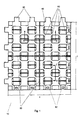
- a support plate 10 according to the invention shown in FIGS. 1 and 2 essentially comprises a support surface 20 formed by partial surfaces 22, 24 and openings 60 connecting the upper and lower surfaces 50 of the support plate 10.
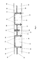
- the partial surfaces 22, 24 are arranged in two planes perpendicular to the top 40 and bottom 50 and separated from each other.
- the arranged in two offset planes faces 22, 24 allow to use the entire surface formed by the dimensions x, y of the platen 10 as a support surface 20.
- the support plate 10 according to the invention has a large contact surface 20. As a result, it does not sink so easily in loose soil, on sand, in the mud or mud.
- the openings 60 are arranged between the two planes formed by the partial surfaces 22, 24.
- the openings have their greatest cross-section in the horizontal direction parallel to the top 40 and bottom 50 of the support plate 10.
- the inter-level openings 60 ensure that, for example, rainwater can seep from the top 40 of the platen 10 into the bottom below the bottom 50.
- a planting may be rooted through the openings 60 in the soil. In this case, the roots of the planting can form under a region covered by the upper side 40 of the support plate 10. The roots are thereby protected against dehydration and trampling.
- the openings 60 are formed by recesses 30, 32 which are arranged alternately in the vertical direction and offset in the horizontal direction and are arranged alternately from the upper side 40 and the underside 50 of the support plate 10.
- the recesses 30, 32 are not formed continuously.
- recesses 34 are additionally arranged recesses 34 at the same points from the bottom 50 forth as the recesses 32 from the top. In principle, it is conceivable to dispense with the recesses 34. In In this case, the partial surfaces 22 would be flush with the underside 50 of the support plate 10 (FIGS. 3 and 4).
- the recesses 34 improve the drainage effect by better dissipation of rainwater into the ground.
- Planting may grow in the non-continuous recesses 32 extending from the top 40 of the platen 10 to the openings 60 formed by the plains 22, 24.
- grass can grow laterally from the recesses 30 through the openings 60 into the recesses 32. As a result, it can not be completely crushed or eroded.
- the grass roots are located below the partial surfaces 24 and thus have a dry-out protection.
- the support surface 20 occupies 90% of the surface formed by the external dimensions x, y.
- the support plate 10 thereby has a very high sinking resistance.
- Such a high proportion of closed support surface 20 at the same time good drainage effect is achieved by the also described as a floor arrangement arrangement of the support surface 20 forming partial surfaces 22, 24 in staggered planes.
- the support plate 10 Between the recesses 30, 32, 34 webs 70 are arranged, through which the openings 60 pass.
- the webs 70 between the partial surfaces 22, 24 are opened in two directions, so that the openings 60 extend in at least two directions between the planes offset in the vertical direction. This allows rainwater to penetrate the entire area covered by the platen 10.
- the entire support plate thus forms a drainage surface, the support plate 10 according to the invention thus allows a water storage of up to 10 1 / m2.
- the support plate according to the invention has the advantage over the prior art that it is ensured by the at least one desired bending point acting in at least one direction.
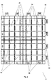
- each support plate 10 as a joint 80 executed target bending points.
- each support plate at least two joints 80 effective in different directions are provided. This is particularly advantageous on soft, loose, muddy or marshy ground, since it often happens here that a support plate is supported unevenly from the ground. If this is the case, the support plate can escape through the desired bending point of a load until the underlying substrate is sufficiently compacted, and can counteract the burden.
- two effective in different directions arranged at right angles to each other desired bending points within the platen even better load distribution is achieved in an overload.
- the support plate 10 has on its narrow sides arranged pin 90 and corresponding recesses 92 ais means for connecting adjacent support plates 10 (Fig. 1).
- the pins 90 can engage in the horizontal direction in the recesses 92 of an adjacent support plate 10, whereby an uneven sinking of adjacent support plates 10 is prevented.
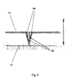
- the support plate 15 shown in FIGS. 5 and 6 has means 82 for expansion compensation in the event of tension or pressure occurring within a plane 17 formed by the support plate 15.
- the expansion compensating means 82 are formed in the support plate 15 as a V-shaped portion 84 formed in a vertical cross section shown in FIG. The cross-section illustrated in FIG. 5 runs along the line E - F shown in FIG. 6.
- the V-shaped section 84 can be continuous or, as shown in FIG. 6, section-wise.
- Formed as a V-shaped portion 84 means 82 for expansion compensation simultaneously form at least one acting in at least one direction of desired bending point within the support plate 15th
- the support plate 15, apart from the formed as a V-shaped portion 84 means 82 for expansion compensation can be designed exactly as the support plate 10 shown in FIGS. 1 to 4. It is conceivable that the joints 80th is dispensed with and their function is fulfilled by the formed as a V-shaped portion 84 82 for expansion compensation.
- the invention is particularly industrially applicable in the field of production of support plates for laying on loose and / or soft ground, on lawns, sports and equestrian facilities, foot and vehicle paths and the like.
Landscapes
- Engineering & Computer Science (AREA)
- Architecture (AREA)
- Civil Engineering (AREA)
- Structural Engineering (AREA)
- Road Paving Structures (AREA)
Applications Claiming Priority (1)
| Application Number | Priority Date | Filing Date | Title |
|---|---|---|---|
| DE102006028404.6A DE102006028404B4 (de) | 2006-06-19 | 2006-06-19 | Auflageplatte zum Verlegen auf dem Boden |
Publications (2)
| Publication Number | Publication Date |
|---|---|
| EP1870518A2 true EP1870518A2 (fr) | 2007-12-26 |
| EP1870518A3 EP1870518A3 (fr) | 2008-05-21 |
Family
ID=38476102
Family Applications (1)
| Application Number | Title | Priority Date | Filing Date |
|---|---|---|---|
| EP07011943A Withdrawn EP1870518A3 (fr) | 2006-06-19 | 2007-06-19 | Plaque de support, en particulier panneau de sol |
Country Status (2)
| Country | Link |
|---|---|
| EP (1) | EP1870518A3 (fr) |
| DE (1) | DE102006028404B4 (fr) |
Families Citing this family (1)
| Publication number | Priority date | Publication date | Assignee | Title |
|---|---|---|---|---|
| DE102009032701A1 (de) | 2009-07-09 | 2011-01-13 | STÄBLER, Karl | Auflageplatte mit in Reihen und Spalten versetzt zueinander angeordneten, quadratischen Plattenteilen und Aufnahmekammern |
Citations (2)
| Publication number | Priority date | Publication date | Assignee | Title |
|---|---|---|---|---|
| DE9216549U1 (de) | 1992-12-04 | 1994-04-07 | Prestele, Eugen, 86161 Augsburg | Gitterplatte |
| DE9403484U1 (de) | 1994-03-02 | 1995-03-30 | Pelikan Gmbh, 30177 Hannover | Formstein |
Family Cites Families (14)
| Publication number | Priority date | Publication date | Assignee | Title |
|---|---|---|---|---|
| DE2608871A1 (de) * | 1976-03-04 | 1977-09-08 | Sf Vollverbundstein | Platte zum herstellen von erdreichabdeckungen sowie verfahren zum verlegen derselben |
| DE2724329C2 (de) * | 1977-05-28 | 1984-08-02 | Gummiwerk Kraiburg Elastik Gmbh & Co, 8261 Tittmoning | Bodenelement für die Herstellung von Sicherheitsböden |
| DE2814095C3 (de) * | 1978-04-01 | 1982-12-09 | Fa. Helmut Stangel u. Rainer Wichert Decken- und Akustikbau, 5800 Hagen | Verbinder für zwei sich kreuzende, übereinanderliegende Schienen |
| DE9005078U1 (de) * | 1990-05-04 | 1990-08-09 | Ritter, Franz Peter, Ing.(grad.), 8933 Untermeitingen | Rasenbefestigungsplatte |
| DE9109165U1 (de) * | 1991-07-25 | 1991-09-26 | ABO System-Elemente GmbH, 5628 Heiligenhaus | Verbundpflasterstein aus Recycling-Kunststoff |
| DE9301590U1 (de) * | 1993-02-05 | 1993-03-25 | Otto, Günther, 8851 Buchdorf | Bodenbefestigungsplatte |
| DE9310336U1 (de) * | 1993-07-12 | 1993-09-02 | IKUSTO GmbH Industrie-, Kunststoffspritzguss- und Extrudierwerk - eigener Stahlformenbau, 86836 Untermeitingen | Wegplatte aus thermoplastischem Kunststoff |
| CH686296A5 (de) * | 1994-06-22 | 1996-02-29 | Fritz E Ag | Rasenschutzwabe. |
| AT1836U1 (de) * | 1996-06-12 | 1997-12-29 | Fleischhacker Gerhard | Flüssigkeitsdurchlässiger belag |
| DE19720006C2 (de) * | 1997-05-13 | 2002-06-13 | Willibald Hergeth | Bodenbelag und Decke für Sportplätze |
| DE19911409A1 (de) * | 1999-03-15 | 2000-09-21 | Willibald Hergeth | Bodenbelag, Decke und Verfahren zum Anlegen einer Grünfläche |
| DE20121313U1 (de) * | 2001-01-11 | 2002-08-01 | Veeh, Helmut, 97215 Uffenheim | Bodenbelagplatte |
| JP4009543B2 (ja) * | 2003-02-24 | 2007-11-14 | 株式会社阪中緑化資材 | 駐車場に敷設するトレー |
| DE202005015107U1 (de) * | 2005-09-24 | 2005-12-29 | HÜBNER-LEE Ernst Hübner e.K. | Gitterplatte |
-
2006
- 2006-06-19 DE DE102006028404.6A patent/DE102006028404B4/de active Active
-
2007
- 2007-06-19 EP EP07011943A patent/EP1870518A3/fr not_active Withdrawn
Patent Citations (2)
| Publication number | Priority date | Publication date | Assignee | Title |
|---|---|---|---|---|
| DE9216549U1 (de) | 1992-12-04 | 1994-04-07 | Prestele, Eugen, 86161 Augsburg | Gitterplatte |
| DE9403484U1 (de) | 1994-03-02 | 1995-03-30 | Pelikan Gmbh, 30177 Hannover | Formstein |
Also Published As
| Publication number | Publication date |
|---|---|
| DE102006028404B4 (de) | 2021-07-01 |
| DE102006028404A1 (de) | 2007-12-20 |
| EP1870518A3 (fr) | 2008-05-21 |
Similar Documents
| Publication | Publication Date | Title |
|---|---|---|
| EP1177347B1 (fr) | Revetement de sol, couverture et procede pour appliquer des surfaces de vegetation | |
| DE69628182T2 (de) | Zellförmige begrenzungsstruktur | |
| DE29522213U1 (de) | Bewegungsfläche für Pferde, insbesondere Reitplatzaufbau | |
| DE20220368U1 (de) | Formstein aus Beton und Bausatz aus Formsteinen zur Erstellung von Erdreichabdeckungen | |
| EP3483340A1 (fr) | Sols pour terrain d'équitation ou de sport et procédé de fabrication d'un sol pour terrain d'équitation ou de sport | |
| DE19720006C2 (de) | Bodenbelag und Decke für Sportplätze | |
| DE20019812U1 (de) | Bodenbefestigungsmatte | |
| EP2292841A2 (fr) | Sol destiné aux activités équestres | |
| EP0039448A2 (fr) | Paroi constituée par des éléments en béton | |
| DE102006052286B4 (de) | Bodengitter | |
| EP1870518A2 (fr) | Plaque de support, en particulier panneau de sol | |
| EP0829592A1 (fr) | Système pour réaliser des supports pour dalles de terrasses, balcons etc. | |
| EP4023816B1 (fr) | Panneau composite et pose | |
| DE20121313U1 (de) | Bodenbelagplatte | |
| DE8900276U1 (de) | Pflasterstein | |
| WO2003033818A1 (fr) | Ensemble a fixer au sol | |
| DE102020120556B4 (de) | Profil und system zur randeinfassung von flächen | |
| DE19640819A1 (de) | Verlegeelementanordnung für befestigte Rasenflächen | |
| DE102024106382B4 (de) | Kunststoff-Mehrzwecksystem zur Bewässerung und dessen Verwendung | |
| AT525401B1 (de) | Tiefbauwerk für das Führen einer Leitung | |
| EP2213798B1 (fr) | Pavé et surface de circulation dotée de pavés | |
| EP1657363B1 (fr) | Surface à usage sportif et/ou récréatif | |
| EP2331752A1 (fr) | Pavage de sol constitué de blocs moulés | |
| DE19650700C2 (de) | Verbundpflasterstein | |
| DE202025003028U1 (de) | Betonpflasterstein |
Legal Events
| Date | Code | Title | Description |
|---|---|---|---|
| PUAI | Public reference made under article 153(3) epc to a published international application that has entered the european phase |
Free format text: ORIGINAL CODE: 0009012 |
|
| AK | Designated contracting states |
Kind code of ref document: A2 Designated state(s): AT BE BG CH CY CZ DE DK EE ES FI FR GB GR HU IE IS IT LI LT LU LV MC MT NL PL PT RO SE SI SK TR |
|
| AX | Request for extension of the european patent |
Extension state: AL BA HR MK YU |
|
| PUAL | Search report despatched |
Free format text: ORIGINAL CODE: 0009013 |
|
| AK | Designated contracting states |
Kind code of ref document: A3 Designated state(s): AT BE BG CH CY CZ DE DK EE ES FI FR GB GR HU IE IS IT LI LT LU LV MC MT NL PL PT RO SE SI SK TR |
|
| AX | Request for extension of the european patent |
Extension state: AL BA HR MK RS |
|
| 17P | Request for examination filed |
Effective date: 20081121 |
|
| 17Q | First examination report despatched |
Effective date: 20081218 |
|
| AKX | Designation fees paid |
Designated state(s): AT BE BG CH CY CZ DE DK EE ES FI FR GB GR HU IE IS IT LI LT LU LV MC MT NL PL PT RO SE SI SK TR |
|
| STAA | Information on the status of an ep patent application or granted ep patent |
Free format text: STATUS: THE APPLICATION IS DEEMED TO BE WITHDRAWN |
|
| 18D | Application deemed to be withdrawn |
Effective date: 20140103 |