EP1860766A1 - Procede et appareil de commande d'un dispositif de pilotage de puissance electrique - Google Patents
Procede et appareil de commande d'un dispositif de pilotage de puissance electrique Download PDFInfo
- Publication number
- EP1860766A1 EP1860766A1 EP06729835A EP06729835A EP1860766A1 EP 1860766 A1 EP1860766 A1 EP 1860766A1 EP 06729835 A EP06729835 A EP 06729835A EP 06729835 A EP06729835 A EP 06729835A EP 1860766 A1 EP1860766 A1 EP 1860766A1
- Authority
- EP
- European Patent Office
- Prior art keywords
- current command
- command value
- motor
- value
- angular speed
- Prior art date
- Legal status (The legal status is an assumption and is not a legal conclusion. Google has not performed a legal analysis and makes no representation as to the accuracy of the status listed.)
- Granted
Links
Images
Classifications
-
- H—ELECTRICITY
- H02—GENERATION; CONVERSION OR DISTRIBUTION OF ELECTRIC POWER
- H02P—CONTROL OR REGULATION OF ELECTRIC MOTORS, ELECTRIC GENERATORS OR DYNAMO-ELECTRIC CONVERTERS; CONTROLLING TRANSFORMERS, REACTORS OR CHOKE COILS
- H02P21/00—Arrangements or methods for the control of electric machines by vector control, e.g. by control of field orientation
- H02P21/02—Arrangements or methods for the control of electric machines by vector control, e.g. by control of field orientation specially adapted for optimising the efficiency at low load
-
- B—PERFORMING OPERATIONS; TRANSPORTING
- B62—LAND VEHICLES FOR TRAVELLING OTHERWISE THAN ON RAILS
- B62D—MOTOR VEHICLES; TRAILERS
- B62D5/00—Power-assisted or power-driven steering
- B62D5/04—Power-assisted or power-driven steering electrical, e.g. using an electric servo-motor connected to, or forming part of, the steering gear
- B62D5/0457—Power-assisted or power-driven steering electrical, e.g. using an electric servo-motor connected to, or forming part of, the steering gear characterised by control features of the drive means as such
- B62D5/046—Controlling the motor
- B62D5/0463—Controlling the motor calculating assisting torque from the motor based on driver input
-
- B—PERFORMING OPERATIONS; TRANSPORTING
- B62—LAND VEHICLES FOR TRAVELLING OTHERWISE THAN ON RAILS
- B62D—MOTOR VEHICLES; TRAILERS
- B62D5/00—Power-assisted or power-driven steering
-
- B—PERFORMING OPERATIONS; TRANSPORTING
- B62—LAND VEHICLES FOR TRAVELLING OTHERWISE THAN ON RAILS
- B62D—MOTOR VEHICLES; TRAILERS
- B62D5/00—Power-assisted or power-driven steering
- B62D5/04—Power-assisted or power-driven steering electrical, e.g. using an electric servo-motor connected to, or forming part of, the steering gear
- B62D5/0457—Power-assisted or power-driven steering electrical, e.g. using an electric servo-motor connected to, or forming part of, the steering gear characterised by control features of the drive means as such
- B62D5/046—Controlling the motor
-
- H—ELECTRICITY
- H02—GENERATION; CONVERSION OR DISTRIBUTION OF ELECTRIC POWER
- H02P—CONTROL OR REGULATION OF ELECTRIC MOTORS, ELECTRIC GENERATORS OR DYNAMO-ELECTRIC CONVERTERS; CONTROLLING TRANSFORMERS, REACTORS OR CHOKE COILS
- H02P21/00—Arrangements or methods for the control of electric machines by vector control, e.g. by control of field orientation
- H02P21/0085—Arrangements or methods for the control of electric machines by vector control, e.g. by control of field orientation specially adapted for high speeds, e.g. above nominal speed
- H02P21/0089—Arrangements or methods for the control of electric machines by vector control, e.g. by control of field orientation specially adapted for high speeds, e.g. above nominal speed using field weakening
-
- H—ELECTRICITY
- H02—GENERATION; CONVERSION OR DISTRIBUTION OF ELECTRIC POWER
- H02P—CONTROL OR REGULATION OF ELECTRIC MOTORS, ELECTRIC GENERATORS OR DYNAMO-ELECTRIC CONVERTERS; CONTROLLING TRANSFORMERS, REACTORS OR CHOKE COILS
- H02P21/00—Arrangements or methods for the control of electric machines by vector control, e.g. by control of field orientation
- H02P21/04—Arrangements or methods for the control of electric machines by vector control, e.g. by control of field orientation specially adapted for very low speeds
-
- H—ELECTRICITY
- H02—GENERATION; CONVERSION OR DISTRIBUTION OF ELECTRIC POWER
- H02P—CONTROL OR REGULATION OF ELECTRIC MOTORS, ELECTRIC GENERATORS OR DYNAMO-ELECTRIC CONVERTERS; CONTROLLING TRANSFORMERS, REACTORS OR CHOKE COILS
- H02P27/00—Arrangements or methods for the control of AC motors characterised by the kind of supply voltage
- H02P27/04—Arrangements or methods for the control of AC motors characterised by the kind of supply voltage using variable-frequency supply voltage, e.g. inverter or converter supply voltage
Definitions
- Electric power steering apparatuses using motor torque to provide a power assist to steering are widely used in automobiles so as to allow a light steering operation.
- Such an electric power steering system includes a geared or belted transmission mechanism transmitting the driving force of a motor through a reducer to provide the power assist to a steering shaft or a rack shaft.
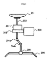
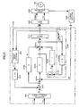
- FIG. 1 shows a typical structure of such an electric power steering system.
- a column shaft 302 of a steering wheel 301 is connected to tie rods 306 of the steering control wheels via reduction gears 303, universal joints 304a and 304b and a pinion-rack mechanism 305.
- the column shaft 302 is provided with a torque sensor 307 for detecting the steering torque of the steering wheel 301.
- a motor 308 assisting the steering force of the steering wheel 301 is connected to the column shaft 302 via the reduction gears 303.
- the torque sensor 307 detects a steering torque generated by a driver's operating force on the steering transmitted from the steering wheel 301, and the motor 308 is driven and controlled by a current command value calculated based on a torque signal and a vehicle speed signal.
- This drive provides the power assist to the driver's operation of the steering wheel 1 and thereby gives the driver a light steering operation.
- the steering feel of the steering wheel as well as the performance of the electric power steering system significantly depend on: the current command value determined on the basis of the steering torque produced by a steering wheel operation; and the method of controlling the motor 308 based on the current command value.
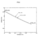
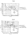
- the normal operating range of a motor can be defined by a torque-speed characteristic (T-n characteristic) derived from a motor output equation.
- T-n characteristic torque-speed characteristic
- T 0 Kt ⁇ I 0
- the locked rotor torque i.e., stall torque
- T-n characteristic a linear torque-speed characteristic
- the T-n characteristic in FIG. 2 represents the performance limit of the motor. Within the range below the T-n characteristic curve in FIG. 2, the motor starts from a stopped condition and runs up to the maximum angular speed to produce the maximum torque possible without exceeding thermal and electrical limits.
- a field-weakening control of a motor vector control can be used to convert the T-n characteristic of the motor exhibiting the characteristic 1 into the T-n characteristic represented by the characteristic curve 4.
- Japanese Patent Application Laid-open No. 2001-18822 A discloses a method for controlling a motor in an electric power steering system by a vector control.
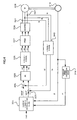
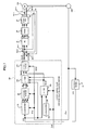
- FIG. 4 shows a basic block diagram of the electric power steering system using the vector control method disclosed in Japanese Patent Application Laid-open No. 2001-18822 A .
- a current command determination means 324 determines d-axis and q-axis current command values idref and iqref based on a torque command value Tref. Meanwhile, current detection means 341 and 342 detect motor currents ia, ib and ic of a motor 308, which are converted, by a three phase-to-two phase conversion means 343, into two axis (d-q axis) currents id and iq. Subtractors 325 and 326 respectively calculate current deviations between the d-axis current command value idref and a feedback current value id and a current deviation between the q-axis current command value iqref and another feedback current value iq.
- the current deviations are inputted to a PI-control means 328, which in turn determines voltage command values vd and vq for reducing the current deviations to zero.
- the motor 308 is a three-phase motor, and the voltage command values vd and vq are converted by a two phase-to-three phase conversion means 336 into three phase voltage command values va, vb and vc.
- a PWM-control means 337 generates PWM-controlled gate signals based on the three-phase voltage command values va, vb and vc.
- An inverter 338 is driven by the gate signals generated by the PWM-control means 337 to supply the motor 308 with currents that reduce the current deviations to zero.
- a resolver 316 detects and feeds the angle (rotational position) ⁇ of the motor 308 to an angular speed conversion means 348 to determine an angular speed (rotational speed) ⁇ used for the vector control.
- the field-weakening control is used in the high-speed range of the motor 308.
- the motor 308 is controlled by the vector control on the basis of a steering assist current command value Iref determined on the basis of steering torque (or vehicle speed and so on) detected by the torque sensor 307.
- Iq Iref Id ⁇ 0
- the PWM-duty saturation results in a current waveform distortion, causing a large torque ripple in the motor, as a result of which, steering wheel vibration or abnormal motor noise is caused.
- FIG. 5 shows a control block diagram disclosed in Japanese Patent Application Laid-open No. 08-142886 A .
- the PWM-duty is forcibly limited to prevent the PWM-duty saturation.
- the steering assist torque is a function of steering torque.
- a required steering assist torque will be too large for the motor to follow immediately. Therefore, the motor cannot provide an accurate steering assist torque.
- a motor current limiting system such as the one described above (involving the limited motor power and the duty saturation) cannot provide a motor current corresponding to the current command value (reference current) directly proportional to the required torque. In this condition, a torque ripple occurs resulting in an unnatural steering feel or abnormal noise.
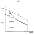
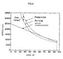
- FIG. 6 shows that the characteristic curve 4 representing the maximum output Pmax is obtained by shifting the characteristic curve 2 representing the rated output Pn by n-offsets ("n os ") in the direction of the rotational speed axis (vertical axis).
- n os n-offsets
- the offset n os can be expressed as angular speed " ⁇ os ". That is, the angular speed ⁇ os is shifted by the offset n os with respect to the direction of the rotational axis.
- the maximum output angular speed is defined as " ⁇ n + ⁇ os " the relationship above will be given by Formula 13 below.
- Pmax Tn ⁇ ⁇ n + ⁇ os
- the present invention is essentially based on the maximum output Pmax, which is the rated output characteristic. This means that, under steady state conditions, the motor must not produce an output exceeding the maximum output Pmax. This requirement can be expressed by Formula 14 below: P ⁇ Pmax
- Ireflim Tlim / Kt ⁇ Tn ⁇ ⁇ n + ⁇ os / ⁇ m / Kt
- Formula 17 means that, based on the maximum output characteristic, which is the rated output characteristic of the motor, the limit value Ireflim of the current command value is determined from a rotational number (angular speed ⁇ m ) of the motor and is used to control the motor drive current.
- Formula 18 makes the use of the torque constant Kt of the motor unnecessary.
- the foregoing Formula 17 or 18 provides the basic formula.
- PVC pseudo-vector control
- the PVC control is a method wherein calculations using the d-axis and q-axis components continue up to the stage of calculating three phase current reference values Iavref, Ibvref and Icvref, and three-phase control is performed at the stage where the motor current is feedbacked for the PI - control.
- the current command value calculator calculates a steering assist current command value Iref based on the steering torque T, the vehicle speed and so on.
- the steering assist current command value Iref is inputted to a converter 106, a q-axis current reference value calculator 103 and a d-axis current reference value calculator 105 in a vector control phase command value calculating section 100.
- a resolver 209 detects and sends the angle ⁇ e of a motor 208 as an input to a differentiation circuit 24 that determines an angular speed ⁇ e .
- a converter 101 receives the angle ⁇ e and the angular speed ⁇ e and calculates phase back EMF ea, eb and ec of the motor 208.
- a three phase-to-two phase converter 102 calculates a d-axis and q-axis back EMF ed and a q-axis back EMF eq.
- a two phase-to-three phase converter 104 receives the d-axis current reference value Idref and the q-axis current reference value Iqref to determine the three phase current reference values Iavref, Ibvref and Icvref.
- a PWM-controller 30 receives the voltage command values Va, Vb and Vc and outputs PWM-gate signals to an inverter 31.
- the inverter 31 is PWM-controlled by the gate signals and current-controlled so that the deviation between each of the phase currents Ia, Ib and Ic and each of the current reference values Iavref, Ibvref and Icvref will be zero.
- ⁇ (Iq 2 + Id 2 ) may exceed the current In at the maximum output.
- An attempt to output a motor current equal to or greater than the current In at the maximum output will result in a duty of 100 %, causing a large torque ripple and problems such as abnormal noise in the motor 208. Therefore, if the angular speed ⁇ e of the motor 208 increases and exceeds the level at which the field-weakening control is performed, it will be necessary to limit the steering assist current command value Iref with the variable limit value Ireflim shown in the above Formula 18. Moreover, if the field-weakening control is performed which exceeds the limit of performance of the motor, another problem will occur in that the noise becomes louder due to a large torque ripple or the like.
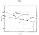
- the required motor torque-speed (T-n) characteristic is specified on the basis of the customer performance specifications.
- the d-axis current command value Id for the field-weakening control is calculated, using the maximum voltage and the current conditions (Vmax, Imax), in response to the input of the steering assist current command value Iref, the motor angular speed ⁇ e , and the battery voltage Vdc.
- Vmax, Imax the maximum voltage and the current conditions
- Iref the steering assist current command value
- ⁇ e the motor angular speed
- Vdc battery voltage
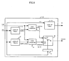
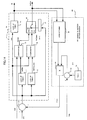
- FIG. 8 shows a configuration of a current command value calculator according to the present invention.
- the steering assist current command value Iref provides an input to comparators 13 and 14.
- An estimated or detected angular speed ⁇ e is inputted to look-up tables 11 and 12 as well as to an additional look-up table 15 and furthermore to a detecting and switching unit 17 that determines whether the angular speed ⁇ e is equal to or greater than the base angular speed ⁇ b to switch contacts c1 and c2 of the switch 16.
- the limit value Ireflim of the current command value determined with the look-up table 11 is inputted to the comparator 13, while the limit value Ireflim_base of the current command value determined with the look-up table 12 is inputted to the comparator 14.
- the battery voltage Vdc is not required.
- the limit value Iref_lim of the current command value outputted from the comparator 13 is supplied to contact c2 of the switch 16, while the base limit value Iref_base of the current command value outputted from the comparator 14 is supplied to contact c1 of the switch 16.
- a square-wave motor can be controlled by the PVC method described above (refer to FIG. 7).
- the waveforms of the current and other variables of a square-wave motor are not sinusoidal.
- d-q expressions cannot be used for the analysis of a square-wave motor.
- introduction of another change amount ⁇ i q and coefficient k allows analysis on the d-q axis.
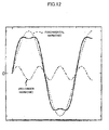
- the back EMF waveform and current waveform of a sinusoidal motor are sinusoidal.
- both the d-axis component (flux control component) and the q-axis component (torque component) will each have a direct current value (constant value).
- the back EMF waveform and current waveform are pseudo-rectangular, and the sinusoidal wave of the first order component is superposed with the sinusoidal waves of the third-, fifth-, seventh-, ⁇ , nth order waves.
- neither the d-axis component nor the q-axis component has a direct current value (constant value).
- Formulas 60 and 61 are relations of the amount ⁇ V of the voltage change and the amount ⁇ of the angular speed.
- the d-axis current limit value approximation formula or supplementary calculation for the relation (look-up table) of the the amount ⁇ V of the voltage change and the amount ⁇ of the angular speed is not needed.
- ⁇ 2 ⁇ ⁇ ⁇ e 2 . ⁇ L 2 . I d 2 + I q 2 + ⁇ 2 + 2.
- ⁇ L . I d . ⁇ ⁇ ⁇ ⁇ ⁇ e ⁇ ⁇ V . 1 L 2 . I d 2 + I d 2 + ⁇ 2 + 2.
- Formula 65 means that the change of the change amount ⁇ is calculated with a look-up table and multiplied by the change amount ⁇ V.
- the hardware implementation of the foregoing calculations is achieved by the configuration shown in FIG. 14.
- This configuration includes a fit-change-to-battery-voltage section 60 and an adder 18 in addition to the current command value calculator in FIG. 8.
- the fit-change-to-battery-voltage section 60 includes a setting section 62 outputting a parameter Vdcn, a subtractor 63 subtracting the parameter Vdcn from the battery voltage Vdc, a look-up table 61 receiving the d-axis current command value Id and the limit value Iref_lim of the current command value from the current command value calculator to output a best-fit value, and a multiplier 64 multiplying a voltage ⁇ V from the subtractor 63 with the best-fit value from the look-up table 61 to output the change amount ⁇ e of the angular speed.
- the change amount ⁇ e in the angular speed determined by the multiplier 64 is inputted to the adder 18. Its sum " ⁇ e + ⁇ e " with the angular speed ⁇ e is inputted to the current command value calculator.
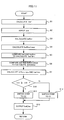
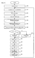
- the steering assist current command value calculator calculates a steering assist current command value Iref based on the steering torque and the vehicle speed (Step S20), and receives the angular speed ⁇ e of the motor 5 and an change amount ⁇ e of the angular speed from the fit-change-to-battery-voltage section 60 to calculate the change amount " ⁇ e + ⁇ e " (Step S21).
- the order of these steps is interchangeable.
- the look-up table 11 is used to determine the limit value Ireflim of the current command value based on the calculated change amount " ⁇ e + ⁇ e " (Step S22), and the look-up table 12 is used to determine the base limit value Iref_base of the current command value (Step S23).
- the limit value Ireflim of the current command value is inputted to the comparator 13, while the base limit value Iref_base of the current command value is inputted to the comparator 14.
- the order of calculation of the limit value Ireflim of the current command value and the base limit value Iref_base of the current command value is interchangeable.
- the look-up table 15 is used to calculate the d-axis current command value Id based on the change amount " ⁇ e + ⁇ e " and the limit value Iref_lim of the current command value (Step S26).
Applications Claiming Priority (2)
| Application Number | Priority Date | Filing Date | Title |
|---|---|---|---|
| JP2005076537 | 2005-03-17 | ||
| PCT/JP2006/305887 WO2006098516A1 (fr) | 2005-03-17 | 2006-03-17 | Procede et appareil de commande d'un dispositif de pilotage de puissance electrique |
Publications (3)
| Publication Number | Publication Date |
|---|---|
| EP1860766A1 true EP1860766A1 (fr) | 2007-11-28 |
| EP1860766A4 EP1860766A4 (fr) | 2011-06-15 |
| EP1860766B1 EP1860766B1 (fr) | 2015-10-28 |
Family
ID=36991852
Family Applications (1)
| Application Number | Title | Priority Date | Filing Date |
|---|---|---|---|
| EP06729835.6A Expired - Fee Related EP1860766B1 (fr) | 2005-03-17 | 2006-03-17 | Procede et appareil de commande d'un dispositif de pilotage de puissance electrique |
Country Status (5)
| Country | Link |
|---|---|
| US (1) | US8285451B2 (fr) |
| EP (1) | EP1860766B1 (fr) |
| JP (1) | JP5024040B2 (fr) |
| KR (1) | KR20070116629A (fr) |
| WO (1) | WO2006098516A1 (fr) |
Cited By (4)
| Publication number | Priority date | Publication date | Assignee | Title |
|---|---|---|---|---|
| EP1892174A1 (fr) * | 2006-08-25 | 2008-02-27 | NSK Ltd. | Dispositif de direction assistée électrique |
| RU2491705C1 (ru) * | 2012-01-10 | 2013-08-27 | Федеральное государственное бюджетное образовательное учреждение высшего профессионального образования "Владимирский государственный университет имени Александра Григорьевича и Николая Григорьевича Столетовых" (ВлГУ) | Электрический привод |
| US8977432B2 (en) | 2008-04-02 | 2015-03-10 | Toyota Jidosha Kabushiki Kaisha | Vehicular steering control apparatus |
| CN108749645A (zh) * | 2018-04-21 | 2018-11-06 | 浙江合众新能源汽车有限公司 | 电动车辆在空挡滑行时的控制保护方法 |
Families Citing this family (45)
| Publication number | Priority date | Publication date | Assignee | Title |
|---|---|---|---|---|
| EP2177413B1 (fr) * | 2004-07-15 | 2015-02-25 | Hitachi, Ltd. | Système de commande de véhicule |
| JP4527596B2 (ja) * | 2005-05-12 | 2010-08-18 | シャープ株式会社 | モータ制御装置およびこれを用いた電気機器 |
| WO2008047698A1 (fr) * | 2006-10-16 | 2008-04-24 | Mitsuba Corporation | Moteur sans balai et procédé de commande d'un moteur sans balai |
| FR2911698B1 (fr) * | 2007-01-24 | 2009-07-10 | Airbus France Sas | Dispositif de commande d'actionneur electromecanique. |
| JP4618614B2 (ja) * | 2007-04-10 | 2011-01-26 | 三菱電機株式会社 | 電動式パワーステアリング制御装置 |
| JP5200460B2 (ja) * | 2007-09-06 | 2013-06-05 | 日本精工株式会社 | モータ駆動制御装置 |
| US9807849B2 (en) * | 2008-09-10 | 2017-10-31 | Enlighted, Inc. | Automatically commissioning lighting controls using sensing parameters of the lighting controls |
| US20100066289A1 (en) * | 2008-09-17 | 2010-03-18 | Ford Global Technologies, Llc | System and method for controlling an electric motor |
| JP5262931B2 (ja) * | 2009-04-01 | 2013-08-14 | トヨタ自動車株式会社 | 電動パワーステアリング装置 |
| WO2011052098A1 (fr) * | 2009-10-30 | 2011-05-05 | トヨタ自動車株式会社 | Dispositif de commande de circulation pour véhicule |
| JP5417195B2 (ja) * | 2010-01-19 | 2014-02-12 | 国産電機株式会社 | 永久磁石モータのトルクリプル抑制制御装置、電動パワーステアリングシステム |
| WO2012037951A2 (fr) * | 2010-09-23 | 2012-03-29 | Thyssenkrupp Presta Ag | Commande d'assistance au conducteur dans un système de direction électrique |
| JP5333422B2 (ja) * | 2010-12-07 | 2013-11-06 | 株式会社デンソー | 電力変換装置 |
| US8552673B2 (en) * | 2011-02-28 | 2013-10-08 | Deere & Company | Interior permanent magnet machine systems and methods for controlling interior permanent magnet machines |
| US8410737B2 (en) * | 2011-02-28 | 2013-04-02 | Deere & Company | Device and method for generating an initial controller lookup table for an IPM machine |
| JP5897298B2 (ja) * | 2011-10-12 | 2016-03-30 | 株式会社ミツバ | ブラシレスモータ制御方法及びブラシレスモータ制御装置並びにブラシレスモータ並びに電動パワーステアリング装置 |
| US8896244B2 (en) * | 2011-12-15 | 2014-11-25 | Steering Solutions Ip Holding Corporation | Motor control system for limiting regenerative current |
| US8924082B2 (en) | 2012-03-30 | 2014-12-30 | Steering Solutions Ip Holding Corporation | System and method for controlling a motor |
| US9663139B2 (en) | 2013-02-26 | 2017-05-30 | Steering Solutions Ip Holding Corporation | Electric motor feedforward control utilizing dynamic motor model |
| GB201304156D0 (en) * | 2013-03-07 | 2013-04-24 | Trw Ltd | Motor Control |
| US9136785B2 (en) | 2013-03-12 | 2015-09-15 | Steering Solutions Ip Holding Corporation | Motor control system to compensate for torque ripple |
| US9143081B2 (en) | 2013-03-14 | 2015-09-22 | Steering Solutions Ip Holding Corporation | Motor control system having bandwidth compensation |
| JP6194466B2 (ja) * | 2013-04-11 | 2017-09-13 | パナソニックIpマネジメント株式会社 | モータ駆動装置 |
| US9199665B2 (en) * | 2013-05-15 | 2015-12-01 | Jtekt Corporation | Electric power steering system |
| DE102013217451A1 (de) * | 2013-09-02 | 2015-03-05 | Robert Bosch Gmbh | Verfahren zur Datenübertragung in einem Batteriemanagementsystem |
| US10389289B2 (en) | 2014-02-06 | 2019-08-20 | Steering Solutions Ip Holding Corporation | Generating motor control reference signal with control voltage budget |
| US10003285B2 (en) | 2014-06-23 | 2018-06-19 | Steering Solutions Ip Holding Corporation | Decoupling current control utilizing direct plant modification in electric power steering system |
| DE112015003203T5 (de) * | 2014-07-10 | 2017-06-22 | Trw Automotive U.S. Llc | System und Verfahren zur robusten aktiven Störungsunterdrückung bei einer elektrischen Servolenkung |
| KR102300785B1 (ko) * | 2014-10-07 | 2021-09-13 | 현대모비스 주식회사 | 전동식 파워 스티어링 구동용 모터의 제어장치 및 방법 |
| US9809247B2 (en) | 2015-01-30 | 2017-11-07 | Steering Solutions Ip Holding Corporation | Motor control current sensor loss of assist mitigation for electric power steering |
| EP3277375B1 (fr) | 2015-04-01 | 2020-12-23 | Yale University | Particules de platine et de fer pour l'adhérence d'agents biologiques sur des implants médicaux |
| WO2016178262A1 (fr) * | 2015-05-01 | 2016-11-10 | 三菱電機株式会社 | Dispositif de commande de direction assistée électrique et procédé de commande de direction assistée électrique |
| KR101684538B1 (ko) * | 2015-06-18 | 2016-12-08 | 현대자동차 주식회사 | 하이브리드 차량의 인버터 제어 방법 |
| JP6445937B2 (ja) * | 2015-07-03 | 2018-12-26 | 日立オートモティブシステムズ株式会社 | 電動パワーステアリング装置 |
| JP6138881B2 (ja) * | 2015-09-25 | 2017-05-31 | 株式会社Subaru | 操舵支援制御装置 |
| US10618544B2 (en) | 2016-05-20 | 2020-04-14 | Steering Solutions Ip Holding Corporation | Radially preloaded rack bearing |
| US11290042B2 (en) * | 2016-05-25 | 2022-03-29 | Steering Solutions Ip Holding Corporation | Supply current limiting of DC machines |
| US10530282B2 (en) * | 2016-05-25 | 2020-01-07 | Steering Solutions Ip Holding Corporation | Current capability limiting of DC machines |
| US10135368B2 (en) | 2016-10-01 | 2018-11-20 | Steering Solutions Ip Holding Corporation | Torque ripple cancellation algorithm involving supply voltage limit constraint |
| JP6237938B1 (ja) * | 2016-10-18 | 2017-11-29 | 株式会社安川電機 | 多軸モータ制御システム、モータ制御装置、及びモータ制御方法 |
| DE102017210747A1 (de) | 2017-06-27 | 2018-12-27 | Bayerische Motoren Werke Aktiengesellschaft | Verfahren zum Vorwärmen einer Batterie eines elektrisch betriebenen Kraftfahrzeugs sowie Ladevorrichtung |
| US11198466B2 (en) | 2017-11-03 | 2021-12-14 | Steering Solutions Ip Holding Corporation | Wedge adjuster plug |
| US11177762B2 (en) * | 2019-02-20 | 2021-11-16 | Volvo Car Corporation | Electric motor control for preventing torque ripple |
| JP2021079893A (ja) | 2019-11-22 | 2021-05-27 | 株式会社ジェイテクト | 操舵制御装置 |
| US11926221B2 (en) * | 2020-09-24 | 2024-03-12 | GM Global Technology Operations LLC | Open-loop control for transient operation of a rotary electric machine |
Citations (8)
| Publication number | Priority date | Publication date | Assignee | Title |
|---|---|---|---|---|
| JPS60197183A (ja) * | 1984-03-19 | 1985-10-05 | Mitsubishi Electric Corp | 誘導電動機の速度制御装置 |
| US5299648A (en) * | 1991-07-22 | 1994-04-05 | Jidosha Kiki Co., Ltd. | Driver current limiting method in electric power steering apparatus |
| EP0638457A2 (fr) * | 1993-08-10 | 1995-02-15 | Toyota Jidosha Kabushiki Kaisha | Méthode et appareil pour l'entraînement et contrôle d'un moteur synchrone utilisant des aimants permanents comme système d'excitation |
| US5656911A (en) * | 1994-12-27 | 1997-08-12 | Fuji Electric Company | Circuit for driving permanent-magnet synchronous motor using proportional controller |
| FR2825853A1 (fr) * | 2001-06-12 | 2002-12-13 | Siemens Automotive Sa | Procede de controle d'un moteur synchrone |
| DE10216104A1 (de) * | 2002-04-12 | 2003-11-06 | Zf Lenksysteme Gmbh | Verfahren zum Betrieb eines Lenksystems für ein Kraftfahrzeug |
| US20040217729A1 (en) * | 2003-04-30 | 2004-11-04 | Visteon Global Technologies, Inc. | Electric power assist steering system and method of operation |
| EP1662650A1 (fr) * | 2004-11-25 | 2006-05-31 | Kawasaki Jukogyo Kabushiki Kaisha | Méthode et système de commande d'un moteur synchrone |
Family Cites Families (18)
| Publication number | Priority date | Publication date | Assignee | Title |
|---|---|---|---|---|
| JPH0530485U (ja) * | 1991-09-28 | 1993-04-23 | 光洋精工株式会社 | ベーンポンプ |
| JP3117880B2 (ja) * | 1993-09-17 | 2000-12-18 | 松下電器産業株式会社 | 同期モータのベクトル制御における弱め界磁制御方法 |
| JP2944867B2 (ja) * | 1993-10-26 | 1999-09-06 | 三菱電機株式会社 | 電動パワーステアリング制御装置 |
| JPH089699A (ja) * | 1994-06-15 | 1996-01-12 | Matsushita Electric Ind Co Ltd | モータの制御方法 |
| JP3358329B2 (ja) * | 1994-10-06 | 2002-12-16 | 日本精工株式会社 | 電動パワーステアリング装置の制御装置 |
| US5758741A (en) * | 1994-10-31 | 1998-06-02 | Jidosha Kiki Co., Ltd. | Vehicle power steering system |
| JP3531250B2 (ja) | 1994-11-24 | 2004-05-24 | 日本精工株式会社 | 電動パワーステアリング装置の制御装置 |
| US6013994A (en) * | 1996-10-01 | 2000-01-11 | Nsk Ltd. | Controller of electric power-steering system |
| JP3497746B2 (ja) * | 1998-10-26 | 2004-02-16 | 本田技研工業株式会社 | 電動パワーステアリング装置 |
| JP3433701B2 (ja) | 1999-07-08 | 2003-08-04 | トヨタ自動車株式会社 | 車両の電動パワーステアリング装置 |
| JP3781653B2 (ja) * | 2001-03-12 | 2006-05-31 | 株式会社ジェイテクト | 電動パワーステアリング装置 |
| JP3982739B2 (ja) * | 2001-05-08 | 2007-09-26 | 本田技研工業株式会社 | 電動パワーステアリング装置 |
| JP3480843B2 (ja) | 2001-09-04 | 2003-12-22 | 三菱電機株式会社 | 電動パワーステアリング制御装置及び制御方法 |
| JP3849979B2 (ja) * | 2002-07-02 | 2006-11-22 | 本田技研工業株式会社 | 電動パワーステアリング装置 |
| JP2004201487A (ja) * | 2002-11-28 | 2004-07-15 | Nsk Ltd | モータ及びその駆動制御装置 |
| JP2005007991A (ja) * | 2003-06-18 | 2005-01-13 | Unisia Jkc Steering System Co Ltd | 電動パワーステアリング装置 |
| JP4604493B2 (ja) * | 2004-01-13 | 2011-01-05 | 日本精工株式会社 | 電動パワーステアリング装置の制御装置 |
| JP4422567B2 (ja) * | 2004-06-30 | 2010-02-24 | 株式会社日立製作所 | モータ駆動装置,電動アクチュエータおよび電動パワーステアリング装置 |
-
2006
- 2006-03-17 KR KR1020077023059A patent/KR20070116629A/ko not_active Application Discontinuation
- 2006-03-17 JP JP2007508261A patent/JP5024040B2/ja not_active Expired - Fee Related
- 2006-03-17 EP EP06729835.6A patent/EP1860766B1/fr not_active Expired - Fee Related
- 2006-03-17 US US11/908,887 patent/US8285451B2/en active Active
- 2006-03-17 WO PCT/JP2006/305887 patent/WO2006098516A1/fr active Application Filing
Patent Citations (8)
| Publication number | Priority date | Publication date | Assignee | Title |
|---|---|---|---|---|
| JPS60197183A (ja) * | 1984-03-19 | 1985-10-05 | Mitsubishi Electric Corp | 誘導電動機の速度制御装置 |
| US5299648A (en) * | 1991-07-22 | 1994-04-05 | Jidosha Kiki Co., Ltd. | Driver current limiting method in electric power steering apparatus |
| EP0638457A2 (fr) * | 1993-08-10 | 1995-02-15 | Toyota Jidosha Kabushiki Kaisha | Méthode et appareil pour l'entraînement et contrôle d'un moteur synchrone utilisant des aimants permanents comme système d'excitation |
| US5656911A (en) * | 1994-12-27 | 1997-08-12 | Fuji Electric Company | Circuit for driving permanent-magnet synchronous motor using proportional controller |
| FR2825853A1 (fr) * | 2001-06-12 | 2002-12-13 | Siemens Automotive Sa | Procede de controle d'un moteur synchrone |
| DE10216104A1 (de) * | 2002-04-12 | 2003-11-06 | Zf Lenksysteme Gmbh | Verfahren zum Betrieb eines Lenksystems für ein Kraftfahrzeug |
| US20040217729A1 (en) * | 2003-04-30 | 2004-11-04 | Visteon Global Technologies, Inc. | Electric power assist steering system and method of operation |
| EP1662650A1 (fr) * | 2004-11-25 | 2006-05-31 | Kawasaki Jukogyo Kabushiki Kaisha | Méthode et système de commande d'un moteur synchrone |
Non-Patent Citations (1)
| Title |
|---|
| See also references of WO2006098516A1 * |
Cited By (4)
| Publication number | Priority date | Publication date | Assignee | Title |
|---|---|---|---|---|
| EP1892174A1 (fr) * | 2006-08-25 | 2008-02-27 | NSK Ltd. | Dispositif de direction assistée électrique |
| US8977432B2 (en) | 2008-04-02 | 2015-03-10 | Toyota Jidosha Kabushiki Kaisha | Vehicular steering control apparatus |
| RU2491705C1 (ru) * | 2012-01-10 | 2013-08-27 | Федеральное государственное бюджетное образовательное учреждение высшего профессионального образования "Владимирский государственный университет имени Александра Григорьевича и Николая Григорьевича Столетовых" (ВлГУ) | Электрический привод |
| CN108749645A (zh) * | 2018-04-21 | 2018-11-06 | 浙江合众新能源汽车有限公司 | 电动车辆在空挡滑行时的控制保护方法 |
Also Published As
| Publication number | Publication date |
|---|---|
| US20090234538A1 (en) | 2009-09-17 |
| WO2006098516A1 (fr) | 2006-09-21 |
| KR20070116629A (ko) | 2007-12-10 |
| JP5024040B2 (ja) | 2012-09-12 |
| JPWO2006098516A1 (ja) | 2008-08-28 |
| US8285451B2 (en) | 2012-10-09 |
| EP1860766B1 (fr) | 2015-10-28 |
| EP1860766A4 (fr) | 2011-06-15 |
Similar Documents
| Publication | Publication Date | Title |
|---|---|---|
| EP1860766B1 (fr) | Procede et appareil de commande d'un dispositif de pilotage de puissance electrique | |
| US7474067B2 (en) | Electric power steering system | |
| US6427104B1 (en) | Steering control apparatus | |
| EP1276225B1 (fr) | Control de moteur réduisant les harmoniques de courant | |
| US7969106B2 (en) | Vector controller for permanent-magnet synchronous electric motor | |
| EP1470988B1 (fr) | Direction assistée électrique | |
| JP5130716B2 (ja) | モータ制御装置および電気式動力舵取装置 | |
| US8686672B2 (en) | Motor control device and electric power steering device | |
| US8874316B2 (en) | Vehicle steering system | |
| EP2228896B1 (fr) | Contrôleur de couple pour moteur synchrone à aimant permanent | |
| WO2009123113A1 (fr) | Dispositif de commande de moteur et dispositif de direction assistée électrique | |
| EP1881596A1 (fr) | Dispositif de regulation de systeme de commande moteur et vehicule electrique utilisant ledit dispositif | |
| EP1672780A2 (fr) | Méthode de réglage du angle de pré-control et un dispositif pour opérer un moteur synchrone à aimants permanents au région d'affaiblissement du champ | |
| EP1843462B1 (fr) | Contrôleur de moteur sans balai | |
| US9548688B2 (en) | Motor control apparatus | |
| US8823300B2 (en) | Electric motor control device | |
| JP4797565B2 (ja) | モータ駆動制御装置 | |
| JP4650110B2 (ja) | 電動機の制御装置 | |
| EP2066018A2 (fr) | Dispositif de commande de moteur | |
| JP4299628B2 (ja) | 電動パワーステアリング装置の制御装置 | |
| JP2008068666A (ja) | 電動パワーステアリング装置 | |
| JP2010029027A (ja) | モータ制御装置 | |
| JP3323900B2 (ja) | リニアモータ電気車の制御装置 | |
| US20240063746A1 (en) | Controller for rotary machine | |
| JP4682521B2 (ja) | 誘導電動機の可変速制御装置 |
Legal Events
| Date | Code | Title | Description |
|---|---|---|---|
| PUAI | Public reference made under article 153(3) epc to a published international application that has entered the european phase |
Free format text: ORIGINAL CODE: 0009012 |
|
| 17P | Request for examination filed |
Effective date: 20070918 |
|
| AK | Designated contracting states |
Kind code of ref document: A1 Designated state(s): DE FR GB |
|
| DAX | Request for extension of the european patent (deleted) | ||
| RBV | Designated contracting states (corrected) |
Designated state(s): DE FR GB |
|
| A4 | Supplementary search report drawn up and despatched |
Effective date: 20110512 |
|
| 17Q | First examination report despatched |
Effective date: 20120702 |
|
| GRAP | Despatch of communication of intention to grant a patent |
Free format text: ORIGINAL CODE: EPIDOSNIGR1 |
|
| GRAJ | Information related to disapproval of communication of intention to grant by the applicant or resumption of examination proceedings by the epo deleted |
Free format text: ORIGINAL CODE: EPIDOSDIGR1 |
|
| GRAP | Despatch of communication of intention to grant a patent |
Free format text: ORIGINAL CODE: EPIDOSNIGR1 |
|
| INTG | Intention to grant announced |
Effective date: 20150429 |
|
| INTG | Intention to grant announced |
Effective date: 20150511 |
|
| GRAS | Grant fee paid |
Free format text: ORIGINAL CODE: EPIDOSNIGR3 |
|
| GRAA | (expected) grant |
Free format text: ORIGINAL CODE: 0009210 |
|
| AK | Designated contracting states |
Kind code of ref document: B1 Designated state(s): DE FR GB |
|
| REG | Reference to a national code |
Ref country code: GB Ref legal event code: FG4D |
|
| REG | Reference to a national code |
Ref country code: DE Ref legal event code: R096 Ref document number: 602006047079 Country of ref document: DE |
|
| REG | Reference to a national code |
Ref country code: FR Ref legal event code: PLFP Year of fee payment: 11 |
|
| REG | Reference to a national code |
Ref country code: DE Ref legal event code: R097 Ref document number: 602006047079 Country of ref document: DE |
|
| PLBE | No opposition filed within time limit |
Free format text: ORIGINAL CODE: 0009261 |
|
| STAA | Information on the status of an ep patent application or granted ep patent |
Free format text: STATUS: NO OPPOSITION FILED WITHIN TIME LIMIT |
|
| 26N | No opposition filed |
Effective date: 20160729 |
|
| REG | Reference to a national code |
Ref country code: FR Ref legal event code: PLFP Year of fee payment: 12 |
|
| REG | Reference to a national code |
Ref country code: FR Ref legal event code: PLFP Year of fee payment: 13 |
|
| PGFP | Annual fee paid to national office [announced via postgrant information from national office to epo] |
Ref country code: DE Payment date: 20200303 Year of fee payment: 15 Ref country code: GB Payment date: 20200304 Year of fee payment: 15 |
|
| PGFP | Annual fee paid to national office [announced via postgrant information from national office to epo] |
Ref country code: FR Payment date: 20200214 Year of fee payment: 15 |
|
| REG | Reference to a national code |
Ref country code: DE Ref legal event code: R119 Ref document number: 602006047079 Country of ref document: DE |
|
| GBPC | Gb: european patent ceased through non-payment of renewal fee |
Effective date: 20210317 |
|
| PG25 | Lapsed in a contracting state [announced via postgrant information from national office to epo] |
Ref country code: DE Free format text: LAPSE BECAUSE OF NON-PAYMENT OF DUE FEES Effective date: 20211001 Ref country code: GB Free format text: LAPSE BECAUSE OF NON-PAYMENT OF DUE FEES Effective date: 20210317 Ref country code: FR Free format text: LAPSE BECAUSE OF NON-PAYMENT OF DUE FEES Effective date: 20210331 |