EP1848202A2 - Ajusteur de quantité légère et appareil d'imagerie - Google Patents
Ajusteur de quantité légère et appareil d'imagerie Download PDFInfo
- Publication number
- EP1848202A2 EP1848202A2 EP07106526A EP07106526A EP1848202A2 EP 1848202 A2 EP1848202 A2 EP 1848202A2 EP 07106526 A EP07106526 A EP 07106526A EP 07106526 A EP07106526 A EP 07106526A EP 1848202 A2 EP1848202 A2 EP 1848202A2
- Authority
- EP
- European Patent Office
- Prior art keywords
- filter members
- light path
- gradation
- light
- region
- Prior art date
- Legal status (The legal status is an assumption and is not a legal conclusion. Google has not performed a legal analysis and makes no representation as to the accuracy of the status listed.)
- Withdrawn
Links
- 238000003384 imaging method Methods 0.000 title claims description 78
- 238000002834 transmittance Methods 0.000 claims abstract description 74
- 102100029469 WD repeat and HMG-box DNA-binding protein 1 Human genes 0.000 claims description 50
- 101710097421 WD repeat and HMG-box DNA-binding protein 1 Proteins 0.000 claims description 50
- 230000007704 transition Effects 0.000 claims description 24
- 238000000926 separation method Methods 0.000 claims description 21
- 230000003287 optical effect Effects 0.000 claims description 12
- 238000013500 data storage Methods 0.000 claims description 9
- 238000013459 approach Methods 0.000 claims description 6
- 239000011521 glass Substances 0.000 claims description 5
- 230000001681 protective effect Effects 0.000 claims description 5
- 239000000284 extract Substances 0.000 claims description 4
- 238000009826 distribution Methods 0.000 description 26
- 230000000694 effects Effects 0.000 description 18
- 230000015556 catabolic process Effects 0.000 description 16
- 238000006731 degradation reaction Methods 0.000 description 16
- 230000008859 change Effects 0.000 description 10
- 230000007246 mechanism Effects 0.000 description 8
- 230000003466 anti-cipated effect Effects 0.000 description 7
- 230000002238 attenuated effect Effects 0.000 description 6
- 238000003780 insertion Methods 0.000 description 6
- 230000037431 insertion Effects 0.000 description 6
- 230000004075 alteration Effects 0.000 description 5
- 230000006870 function Effects 0.000 description 4
- 230000033001 locomotion Effects 0.000 description 4
- 230000007257 malfunction Effects 0.000 description 4
- 238000013461 design Methods 0.000 description 3
- 238000004519 manufacturing process Methods 0.000 description 3
- 230000009467 reduction Effects 0.000 description 3
- 230000000717 retained effect Effects 0.000 description 3
- 230000006399 behavior Effects 0.000 description 2
- 230000014509 gene expression Effects 0.000 description 2
- 239000002245 particle Substances 0.000 description 2
- 230000035945 sensitivity Effects 0.000 description 2
- 230000003595 spectral effect Effects 0.000 description 2
- BQCADISMDOOEFD-UHFFFAOYSA-N Silver Chemical compound [Ag] BQCADISMDOOEFD-UHFFFAOYSA-N 0.000 description 1
- 230000002411 adverse Effects 0.000 description 1
- 230000003679 aging effect Effects 0.000 description 1
- 238000000149 argon plasma sintering Methods 0.000 description 1
- 230000008901 benefit Effects 0.000 description 1
- 230000005540 biological transmission Effects 0.000 description 1
- 238000010586 diagram Methods 0.000 description 1
- 238000001914 filtration Methods 0.000 description 1
- 230000006872 improvement Effects 0.000 description 1
- 230000000670 limiting effect Effects 0.000 description 1
- 239000000463 material Substances 0.000 description 1
- 230000004048 modification Effects 0.000 description 1
- 238000012986 modification Methods 0.000 description 1
- 230000008092 positive effect Effects 0.000 description 1
- 230000004044 response Effects 0.000 description 1
- 229910052709 silver Inorganic materials 0.000 description 1
- 239000004332 silver Substances 0.000 description 1
- 238000004088 simulation Methods 0.000 description 1
- 238000003860 storage Methods 0.000 description 1
- 230000001360 synchronised effect Effects 0.000 description 1
Images


Classifications
-
- G—PHYSICS
- G02—OPTICS
- G02B—OPTICAL ELEMENTS, SYSTEMS OR APPARATUS
- G02B26/00—Optical devices or arrangements for the control of light using movable or deformable optical elements
- G02B26/02—Optical devices or arrangements for the control of light using movable or deformable optical elements for controlling the intensity of light
-
- H—ELECTRICITY
- H04—ELECTRIC COMMUNICATION TECHNIQUE
- H04N—PICTORIAL COMMUNICATION, e.g. TELEVISION
- H04N23/00—Cameras or camera modules comprising electronic image sensors; Control thereof
- H04N23/70—Circuitry for compensating brightness variation in the scene
- H04N23/75—Circuitry for compensating brightness variation in the scene by influencing optical camera components
-
- G—PHYSICS
- G03—PHOTOGRAPHY; CINEMATOGRAPHY; ANALOGOUS TECHNIQUES USING WAVES OTHER THAN OPTICAL WAVES; ELECTROGRAPHY; HOLOGRAPHY
- G03B—APPARATUS OR ARRANGEMENTS FOR TAKING PHOTOGRAPHS OR FOR PROJECTING OR VIEWING THEM; APPARATUS OR ARRANGEMENTS EMPLOYING ANALOGOUS TECHNIQUES USING WAVES OTHER THAN OPTICAL WAVES; ACCESSORIES THEREFOR
- G03B11/00—Filters or other obturators specially adapted for photographic purposes
-
- G—PHYSICS
- G03—PHOTOGRAPHY; CINEMATOGRAPHY; ANALOGOUS TECHNIQUES USING WAVES OTHER THAN OPTICAL WAVES; ELECTROGRAPHY; HOLOGRAPHY
- G03B—APPARATUS OR ARRANGEMENTS FOR TAKING PHOTOGRAPHS OR FOR PROJECTING OR VIEWING THEM; APPARATUS OR ARRANGEMENTS EMPLOYING ANALOGOUS TECHNIQUES USING WAVES OTHER THAN OPTICAL WAVES; ACCESSORIES THEREFOR
- G03B7/00—Control of exposure by setting shutters, diaphragms or filters, separately or conjointly
- G03B7/18—Control of exposure by setting shutters, diaphragms or filters, separately or conjointly in accordance with light-reducing "factor" of filter or other obturator used with or on the lens of the camera
-
- G—PHYSICS
- G03—PHOTOGRAPHY; CINEMATOGRAPHY; ANALOGOUS TECHNIQUES USING WAVES OTHER THAN OPTICAL WAVES; ELECTROGRAPHY; HOLOGRAPHY
- G03B—APPARATUS OR ARRANGEMENTS FOR TAKING PHOTOGRAPHS OR FOR PROJECTING OR VIEWING THEM; APPARATUS OR ARRANGEMENTS EMPLOYING ANALOGOUS TECHNIQUES USING WAVES OTHER THAN OPTICAL WAVES; ACCESSORIES THEREFOR
- G03B9/00—Exposure-making shutters; Diaphragms
- G03B9/02—Diaphragms
-
- H—ELECTRICITY
- H04—ELECTRIC COMMUNICATION TECHNIQUE
- H04N—PICTORIAL COMMUNICATION, e.g. TELEVISION
- H04N23/00—Cameras or camera modules comprising electronic image sensors; Control thereof
- H04N23/50—Constructional details
- H04N23/55—Optical parts specially adapted for electronic image sensors; Mounting thereof
Definitions
- the present invention relates to a novel light amount adjuster and imaging apparatus. More particularly, the invention relates to a light amount adjuster that causes little degradation in image quality and is suitable for a camera that uses an imaging device to receive light, such as a video camcorder and a digital still camera, and an imaging apparatus having such a light amount adjuster.
- An aperture stop is generally used as means for adjusting the amount of incident light in an imaging apparatus.
- a small aperture size (a large F-number) disadvantageously results in degradation in image quality due to diffraction.
- ND filters to attenuate the amount of transmitted light.
- JP-A-58-184135 proposes to prevent the aperture stop from being set to a small aperture size by disposing ND filters having several transmittance levels between the lens and the imaging device and switching to an ND filter having appropriate transmittance according to the brightness of the subject.
- JP-A-2004-53633 proposes that in addition to similarly switching among ND filters, a mechanical shutter is used to limit the exposure time.
- JP-A-2005-348140 proposes to automatically switch among the settings of the aperture stop and the ND filter density based on the output signal from the imaging device so as to prevent the aperture stop from being set within the range where diffraction causes significant degradation.
- JP-A-6-90403 proposes to use an ND filter utilizing an electrochromic effect in which transmittance is changed by the applied voltage.
- JP-A-6-90403 JP-A-2006-3437 also proposes to utilize an electrochromic effect in an imaging apparatus using color separation prisms in such a way that a variable density ND filter is disposed between the lens and the prisms.
- JP-A-52-117127 proposes to use a plurality of gradation ND filters whose transmittance continuously changes and use the overlapping portion of the gradation ND filters to change the density.
- JP-A-6-265971 suggests that insertion of the edge of an ND filter member into the aperture causes wavefront phase difference and hence degradation in image quality, and proposes that the aperture is covered with a transparent region when the stop is fully open, while a gradation ND region adjacent to the transparent region is inserted into the aperture so as to adjust the amount of light.
- JP-A-2004-205951 suggests causes of image quality degradation when a filter having a gradation ND region and a transparent region is inserted into the aperture, and suggests that as simulation-based experimental consideration, the image quality degradation is caused by the following three factors; diffraction caused by the region that is surrounded by the diaphragm blades and the ND filter and serves as a small aperture when the filter is inserted halfway into the aperture, large wavefront phase difference generated when the edge of the filter member is present in the aperture, and small wavefront phase difference generated at the border between the transparent region and the gradation ND region of the filter.
- JP-A-2003-241253 proposes a light amount adjuster in which a film base has two portions, each including a transparent region and a ND region, and the ND regions are inserted into the aperture from opposite directions.
- ND filters having different stepwise density levels are prepared and switched such that the aperture size will not be set to a small value.
- insertion and removal of the ND filters to and from the light path affects the moving picture screen, resulting in unnatural reproduced images.
- the ND filters are disposed at a position close to the imaging device and any one of the ND filters covers one-half the light path, one half of the screen becomes bright and the other half of the screen becomes dark, and the boundary between the bright and dark portions moves across the screen when the ND filter is inserted or removed.
- the movement of the boundary will not be so visible.
- changing the F-number of the aperture stop for exposure adjustment will not be carried out fast enough to be synchronized with the change in ND density, resulting in recording of a bright screen at one instant and a dark screen at another instant.
- the ND filters are disposed adjacent to the aperture stop, the movement of the boundary between the bright and dark portions across the screen will not be so visible.
- a foreground or background blurred image appears to move in synchronization with the insertion and removal of the ND filters, and such a phenomenon will be recorded.
- JP-A-52-117127 uses means for progressively covering a predetermined aperture of a diaphragm formed of diaphragm blades with two gradation ND filters, each having a shape similar to that of the diaphragm blade, no consideration is made to the phase difference caused by the edge of the filter member suggested in JP-A-6-265971 and JP-A-2004-205951 .
- gradation ND provides a certain effect of reducing diffraction caused by the open area surrounded by the diaphragm blades and the high-density ND filter and serving as a small aperture.
- the effect of phase difference caused by the edge of the filter member is suggested but not solved.
- the density of the ND filter is ideally uniform and continuously variable in the area where the ND filter covers the light path, the fact that the gradation ND does not have uniform density raises a concern about a side effect.
- a light amount adjuster includes two filter members, each having a gradation ND region where the transmittance continuously changes, disposed such that the two filter members face each other and the direction in which the gradation of one of the filter members changes differs from the direction in which the gradation of the other one of the filter members changes and configured such that the filter members can move in a symmetrical manner with respect to each other.
- a imaging apparatus includes a lens, a light amount adjuster and an imaging device.
- the light amount adjuster includes two filter members, each having a gradation ND region where the transmittance continuously changes, disposed such that the two filter members face each other and the direction in which the gradation of one of the filter members changes differs from the direction in which the gradation of the other one of the filter members changes and configured such that the filter members can move in a symmetrical manner with respect to each other.
- the light amount adjuster includes two filter members, each having a gradation ND region where the transmittance continuously changes, disposed such that the two filter members face each other and the direction in which the gradation of one of the filter members changes differs from the direction in which the gradation of the other one of the filter members changes and configured such that the filter members can move in a symmetrical manner with respect to each other.
- the light amount adjuster according to this embodiment of the invention can prevent diffraction caused by a small aperture size of an aperture stop.
- the light amount adjuster according to this embodiment of the invention can be implemented in the following examples.
- the imaging apparatus includes a lens, a light amount adjuster and an imaging device.
- the light amount adjuster includes two filter members, each having a gradation ND region where the transmittance continuously changes, disposed such that the two filter members face each other and the direction in which the gradation of one of the filter members changes differs from the direction in which the gradation of the other one of the filter members changes and configured such that the filter members can move in a symmetrical manner with respect to each other.
- the imaging apparatus can prevent diffraction caused by a small aperture size of an aperture stop.
- the imaging apparatus according to this embodiment of the invention can be implemented in the following examples.
- Fig. 1 schematically shows the imaging apparatus according to a first embodiment of the invention.
- the imaging apparatus 1 includes a lens L, a light amount adjuster 2 and imaging devices GI, BI and RI.
- the light amount adjuster 2 includes two filter members ND1 and ND2 disposed such that they face each other and can symmetrically move with respect to each other, each of the filter members having a gradation ND region where the transmittance continuously changes and a transparent region where the transmittance is uniform and at least 80%.
- the light amount adjuster 2 is also configured such that in order to provide the highest transmittance, the transparent regions of the two filter members overlap each other and cover the entire light path, while in order to limit the amount of transmitted light, the gradation ND regions are symmetrically inserted into the light path from opposite positions in such a way that the ND density of the gradation ND region in the light path gradually increases so as to attenuate the amount of transmitted light.
- Fig. 2 diagrammatically shows the state where the filter members ND1 and ND2 according to the first embodiment cover the light path LD indicated by the broken line when viewed in the direction in which the light path LD extends.
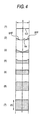
- Fig. 3 diagrammatically shows how the gradation ND filters ND1 and ND2 are progressively inserted into the width A of the light path LD shown in Fig. 2 in such a way that the low density region is first inserted, followed by higher density regions.
- Fig. 4 shows the distribution of ND density versus position in the width A of the light path LD.
- the numbers (1) to (7) labeled in the left part of Fig. 3 correspond to the numbers (1) to (7) labeled in the left part of Fig. 4, and the same numbers indicate the same condition.
- ND density is expressed by the height of the triangle, indicating that the higher the height, the higher the density.
- the portion indicated only by a line is transparent.
- Fig. 4 shows the sum of the overlapping areas of the triangles within the width A of the light path LD in Fig. 3, indicating that the larger the area, the higher the ND density.
- the gradation ND regions gnd of the two gradation ND filters ND1 and ND2 are both retracted from the light path LD, so that the overlapping transparent regions tra cover the light path LD to provide the highest transmittance.
- the gradation ND regions gnd are slightly inserted into the light path LD.
- the filter members ND1 and ND2 are configured such that they are inserted and removed in the vertical direction of the screen, the light at the upper and lower parts of the light path LD will be attenuated.
- the two filter members ND1 and ND2 When the two filter members ND1 and ND2 are symmetrically moved, that is, moved in opposite directions with respect to each other, until the highest density portions are inserted in the light path LD, the two filter members ND1 and ND2 provide the highest density 2D across the light path LD, where D is the density of one of the filter members ND1 and ND2 at the center of the light path LD.
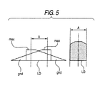
- each of the filter members ND1 and ND2 may have a uniform, highest density region max that follows the gradation ND region gnd, the uniform, highest density region max is desirably controlled not to be inserted in the light path LD.
- Fig. 5 explains the effect in such a case.
- the left part of Fig. 5 corresponds to Fig. 3, and the right part of Fig. 5 corresponds to Fig. 4.
- the density is highest at the center of the light path LD, and the density is lower at the sides where the filter members are inserted.
- the ND density D of one of the filter members ND1 and ND2 is 0.5 to 1.0 at the center of the light path and the length of the gradation ND region gnd in the insertion direction INS (see Fig. 2) is 1.0 to 2.0 times the length A necessary for covering the light path LD.
- the ND density means that the transmittance is the reciprocal of the (ND density)-th power of 10.
- the highest ND density used in representative three-plate cameras presently commercially available is about 1.5 to 1.8.
- the ND density necessary for preventing diffraction due to a small aperture size will not be significantly high.
- the spatial frequency on the imaging device corresponding to the TV resolution on the output screen a smaller screen dimension of the imaging device may require higher MTF than ever at high spatial frequencies. Consequently, the F-number of the stopped-down aperture determined by the diffraction limit may not be larger, so that it is anticipated that the light amount control will depend on a light amount adjuster instead of an aperture stop.
- a reasonable density D to obtain the highest density 2D will be about 0.5 to 1.0.
- the width of the gradation ND region gnd necessary for obtaining flat density distribution is at least 1.0 time the width A of the light path, a width twice the width A or larger increases the travel of the filter members ND1 and ND2, resulting in an increased size of a driving apparatus of the filter members and hence an increased size of the entire imaging apparatus.
- the direction in which the gradation ND regions gnd of the filter members ND1 and ND2 are inserted desirably coincides with the direction in which the prisms separate color.
- the imaging apparatus 1 using the color separation prisms GP, BP and RP it is a well known phenomenon that a blurred image of a point source on the optical axis shows color unevenness of green and magenta in the circle of confusion.
- the direction in which the gradation ND filters ND1 and ND2 are inserted into the light path LD is designed to coincide with the direction in which color separation is carried out so as to symmetrically reduce the cause of deviation to green and the cause of deviation to magenta, allowing reduction in change in white balance and occurrence of color unevenness observed in a blurred point source image.
- the direction in which the gradation ND filters ND1 and ND2 are inserted into the light path LD and the direction in which color separation is carried out are both parallel to the plane of the figure.
- the imaging apparatus 1 desirably includes the lens L having an aperture stop St formed of a plurality of diaphragm blades, the light amount adjuster 2 described above, the color separation prisms GP, BP and RP, and the imaging devices GI, BI and RI in this order from the object side.
- JP-A-52-117127 , JP-A-6-265971 , JP-A-2004-205951 and JP-A-2003-241253 propose that the gradation ND filters are disposed at the same position as the aperture stop, in the light amount adjuster according to an embodiment of the invention, two gradation ND filters are disposed such that they face each other and symmetrically move along a long distance path, so that the cross-sectional area of the light amount adjuster perpendicular to the optical axis becomes inevitably large.
- the light amount adjuster 2 is desirably disposed between the lens L and the color separation prisms GP, BP and RP where space can be relatively easily available.
- the imaging apparatus 1 desirably includes a removable lens L having an aperture stop St formed of a plurality of diaphragm blades, a fixed parallel planar member F1 including one of protective glass, an optical low-pass filter and an infrared-cut filter, the light amount adjuster 2 described above, the color separation prisms GP, BP and RP, and the imaging devices GI, BI and RI in this order from the object side.
- the light amount adjuster 2 that may be formed of thin filters or may include a movement mechanism sensitive to an external force is prone to failure, if the user can touch the light amount adjuster 2 when the lens is removed.
- the fixed parallel planar member F1 including one of protective glass, an optical low-pass filter and an infrared-cut filter is desirably disposed at the entrance of the light path on the body Bd side so as to protect the light amount adjuster 2 disposed behind the fixed parallel planar member F1 when the lens is removed.
- the imaging apparatus 1 shown in Fig. 1 is configured such that an exchanger mount Mt, although its detailed structure is not shown, allows the lens L to be attached and detached.
- the fixed parallel planar member F1 including one of protective glass, an optical low-pass filter and an infrared-cut filter is disposed at the entrance of the light path of the body Bd to protect the light amount adjuster 2. Since the flange focal distance in the body Bd is preferably as short as possible from the lens design point of view, it is further preferable to dispose the fixed parallel planar member F1 having an optical low-pass filter and an infrared-cut filter joined with each other.
- a programmed AE data storage unit memory
- the user switches among ND filters that provide two or three stepwise density levels and uses a combination of the amount of transmitted light attenuated by the selected ND filter and a F-number controlled by the aperture stop so as to adjust the stop within a range where degradation in image quality due to diffraction is acceptable.
- ND filters that provide two or three stepwise density levels
- the aperture stop uses a combination of the amount of transmitted light attenuated by the selected ND filter and a F-number controlled by the aperture stop so as to adjust the stop within a range where degradation in image quality due to diffraction is acceptable.
- extremely narrow variable range of the F-number forces the user to frequently switch among the ND filters.
- AE that automatically adjusts the light amount adjuster according to an embodiment of the invention and the stop eliminates the burden of ND filter switching from the user, allowing a hard-to-operate video camcorder for professional use to have usability similar to that of a user-friendly video camcorder for consumer use.
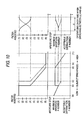
- Fig. 6 shows an example diagrammatically illustrating preferable combinations of the F-number and the amount of transmitted light.
- the horizontal axis indicates subject brightness.
- the numbers (1) to (7) next to the vertical axis of the upper left graph correspond to the numbered states in Figs. 3 and 4 indicating the inserted filter members ND1 and ND2.
- the vertical axis of the lower left graph indicates F-numbers of the aperture stop including the full-aperture F-number and the limit F-number at which degradation in image quality due to diffraction is still acceptable.
- the common horizontal axis for the two left graphs indicates the subject brightness from low brightness (a) to high brightness (g).
- Program charts are expressed by solid lines along the subject brightness making a transition from a low level to a high level, and only portions of the program different from the solid lines when the subject brightness makes a transition from a high level to a low level are shown by broken lines.
- the stop is set to the state (b) where the aperture size is slightly smaller than the full-aperture size, while the filter members ND1 and ND2 are left stationary. Then, the stop is left stationary at the appropriate F-number and the gradation ND regions gnd are inserted into the light path LD to achieve the state (2).
- (c) be the subject brightness in the state (2).
- the filter members ND1 and ND2 are inserted at one stroke to the state (4).
- the stop is opened up such that the illuminance on the image plane will not change.
- JP-A-2004-205951 suggests that wavefront phase difference resulting from the step of the deposited film at the border between the transparent region and the gradation ND region causes degradation in image quality.
- the two steps of the filter members ND1 and ND2 approach each other at the center of the light path LD in the V-shape state (3). Therefore, it is anticipated that degradation in image quality due to the phase difference most likely occurs.
- the filter members ND1 and ND2 as well as the diaphragm blades are simultaneously driven such that the filter members ND1 and ND2 will pass through the V-shape state (3) in a short period of time, so as to move the filter members ND1 and ND2 through the V-shape state (3) at one stroke.
- the two right graphs show how the filter members ND1 and ND2 as well as the stop are driven in the above operation as a function of time (the horizontal axis).
- the states indicating the inserted filter members ND1 and ND2 and the states of the stop in the right respective graphs correspond to those in the left graphs by connecting both sides with the two-dot chain lines.
- the operation of deeply inserting the filter members ND1 and ND2, which reduces the amount of transmitted light, and the operation of opening up the stop to increase the amount of light are coordinated such that the overall illuminance on the image plane will not change.
- the time ct spent for the coordinated switching is preferably 0.2 to 1.5 seconds. Time shorter than 0.2 seconds likely results in an error of the coordinated operation designed not to change the overall illuminance on the image plane, while time longer than 1.5 seconds results in noticeable delay of AE tracking when applied to scenes where the subject brightness sharply changes.
- the charts in the right graphs preferably make a transition like a sinusoidal curve.
- the stop is left stationary, while the filter members ND1 and ND2 are inserted further deeper into the light path LD to adjust the amount of light when the subject brightness changes from (c) to (e).
- the light amount adjuster 2 provides an ideal performance in which the distribution of ND density in the light path LD is flat and only the overall density changes, that is, an effect similar to the electrochromic effect described in JP-A-6-90403 and JP-A-2006-3437 is provided.
- the filter members ND1 and ND2 After the filter members ND1 and ND2 reach their highest density, the filter members ND1 and ND2 will be left stationary and the stop is closed down to the acceptable diffraction F-number for handling high-brightness (g) subjects.
- the subject brightness (d) is higher than (c), which is used when the subject brightness makes a transition to the higher brightness side.
- the transition indicated by the broken lines in the two right graphs shows how the filter members ND1 and ND2 as well as the stop are simultaneously driven at the brightness (d) as a function of time (the horizontal axis).
- the filter members ND1 and ND2 are moved in coordination with the stop in the short period of time ct such that the filter members ND1 and ND2 will not stay in the V-shape state (3).
- Hysteresis behavior between the brightness (c), which is used when the brightness makes a transition to the high brightness side, and the brightness (d), which is used when the brightness makes a transition to the low brightness side prevents hunting and malfunction.
- the programmed AE is desirably configured such that the control is automatically taken over by a fast electronic shutter.
- aperture-priority AE in which the user arbitrarily sets the F-number that is controlled by the aperture stop St formed of a plurality of diaphragm blades and only the amount of transmitted light that is controlled by the light amount adjuster 2 is used or the combination of the amount of transmitted light that is controlled by the light amount adjuster 2 and the electronic shutter is used. Since the light amount adjuster described above can continuously change the density from a substantially transparent state to an ND density of about 2.0, priority can be placed on expressions using pan focusing or blurring obtained by utilizing the depth of field of the lens, producing a variety of image expression effects.
- phase difference of the light having a predetermined wavelength ⁇ that passes through the border bor between the gradation ND region gnd and the transparent region tra is desirably smaller than or equal to ⁇ /10.
- JP-A-2004-205951 suggests that in order to reduce degradation in image quality due to wavefront phase difference resulting from one filter within an acceptable range, it is reasonable to reduce the wavefront phase difference due to the step of the deposited film present at the border between the gradation ND region and the transparent region to ⁇ /5 or smaller. Since two of the filter members are used in an embodiment of the invention, there may be two steps in the light path that cause phase difference in some cases. In the V-shape state in particular, since the steps responsible for phase difference approach each other, it is anticipated that the wavefront is likely disturbed. Therefore, as the condition that may be required for one filter member, it is desirable to further reduce the phase difference to ⁇ /10, which is one-half the phase difference described in JP-A-2004-205951 .
- Fig. 7 shows filter members aND1 and aND2 according to a second embodiment used in the light amount adjuster 2.
- Each of the filter members aND1 and aND2 has a gradation ND region gnd where the transmittance continuously changes and a lowest density region Ind where the transmittance is uniform and 80% or lower.
- the two filter members aND1 and aND2 are disposed such that they face each other and can symmetrically move with respect to each other. To provide the highest transmittance, the two filter members aND1 and aND2 are both retracted from the light path LD.
- one or both of the lowest density regions Ind of the filter members aND1 and aND2 are inserted into the light path LD and cover the entire light path LD, and then, the gradation ND regions gnd are symmetrically inserted into the light path from opposite positions in such a way that the ND density of the gradation ND region gnd in the light path gradually increases so as to attenuate the amount of transmitted light.
- the filter members aND1 and aND2 when the lowest density regions Ind are inserted into and removed from the light path LD, it is desirable to achieve programmed AE in which the F-number and/or the electronic shutter is set and at the same time the filter members aND1 and aND2 are moved according to the transition of subject brightness such that the front ends tip of the filter members aND1 and aND2 will not stop in the light path LD.
- Fig. 7 diagrammatically shows the state where the filter members aND1 and aND2 are retracted from the light path LD indicated by the broken line.
- the lowest density region Ind having uniform density is situated on the closer side of the border line dv with no deposition-thickness step to the light path LD, and the gradation ND region gnd where the density changes from the lowest level to the highest level is situated on the far side of the border line dv from the light path LD.
- Fig. 8 diagrammatically shows how the lowest density regions Ind of the filter members aND1 and aND2 are inserted into the light path LD having the width A shown in Fig.
- Fig. 9 shows the distribution of ND density versus position in the width A of the light path LD.
- the numbers (1) to (8) labeled in the left part of Fig. 8 correspond to the numbers (1) to (8) labeled in the left part of Fig. 9.
- Figs. 7, 8 and 9 are expressed in a way similar to the way Figs. 2, 3 and 4 are expressed, respectively.
- the two filter members aND1 and aND2 are both retracted from the light path LD, so that the highest transmittance is provided.
- the lowest density regions Ind are slightly inserted into the light path LD.
- the filter members aND1 and aND2 are configured such that they are inserted and removed in the vertical direction of the screen, the light at the upper and lower parts of the light path LD will be attenuated.
- part of the lowest density regions Ind of the two filter members aND1 and aND2 overlap each other at the center of the light path LD, so that the distribution of density versus position has a dark band at the center of the light path LD.
- the two lowest density regions Ind overlap each other, so that the density distribution becomes flat.
- the gradation ND regions gnd that follow the lowest density regions Ind are slightly inserted into the light path LD.
- the filter members aND1 and aND2 are configured such that they are inserted and removed in the vertical direction of the screen, the light at the upper and lower parts of the light path LD will be attenuated.
- the borders dv between the lowest density regions Ind and the gradation ND regions gnd of the two filter members aND1 and aND2 come into contact with each other at the center of the light path LD, so that the distribution of density versus position becomes a V-like shape.
- part of the gradation ND regions gnd overlap each other in the light path LD.
- the density distribution at the overlapping portion becomes flat.
- the lowest density regions Ind are completely retracted from the light path LD, so that the density distribution becomes flat across the light path LD.
- the two filter members aND1 and aND2 are symmetrically moved with respect to each other until the highest density portions are inserted in the light path LD, the two filter members aND1 and aND2 provide the highest density 2D across the light path LD, where D is the density of one of the filter members aND1 and aND2 at the center of the light path LD.
- Fig. 10 shows an example diagrammatically illustrating preferable combinations of the F-number and the amount of transmitted light.
- the horizontal axis indicates the subject brightness.
- the numbers (1) to (8) next to the vertical axis of the upper left graph correspond to the numbered states in Figs. 8 and 9 indicating the filter members aND1 and aND2 inserted into the light path LD.
- the vertical axis of the lower left graph indicates F-numbers of the aperture stop including the full-aperture F-number and the limit F-number at which degradation of image quality due to diffraction is still acceptable.
- the common horizontal axis for the two left graphs indicates the subject brightness from high brightness (a) to low brightness (f).
- Program charts are expressed by solid lines along the subject brightness making a transition from a low level to a high level, and only portions of the program different from the solid lines when the subject brightness makes a transition from a high level to a low level are shown by broken lines.
- the two graphs shown in Fig. 10 are used to explain a preferable example of the programmed AE.
- the filter members aND1 and aND2 are retracted from the light path LD and the stop is fully open, so that the amount of transmitted light is highest.
- the stop is set to the state (b) where the aperture size is slightly smaller than the full-aperture size, while the filter members aND1 and aND2 are left stationary. Then, the filter members aND1 and aND2 are inserted at one stroke to the state (4).
- JP-A-2004-205951 suggests that large transmitted wavefront phase difference resulting from the thickness of the filter base causes degradation in image quality.
- the two lowest density regions Ind of the filters overlap each other at the center of the light path in the state (3). Therefore, there are two divided high-transmittance portions, causing two-line blurring, which may lead to malfunction of contrast-based autofocus.
- the two right graphs show how the filter members aND1 and aND2 as well as the stop are driven in the above operation as a function of time (the horizontal axis).
- the states indicating the inserted filter members aND1 and aND2 and the states of the stop in the right respective graphs correspond to those in the left graphs by connecting both sides.
- the operation of deeply inserting the lowest density regions Ind of the two filter members aND1 and aND2 into the light path LD, which reduces the amount of light, and the operation of opening up the stop to increase the amount of light are coordinated such that the overall illuminance on the image plane will not change.
- the stop is left stationary, while the filter members aND1 and aND2 are inserted deeper until the gradation ND regions gnd are inserted to adjust the amount of light when the subject brightness changes from (b) to (d). After the filter members aND1 and aND2 reach their highest density, the filter members aND1 and aND2 will be left stationary and the stop is closed down to the acceptable diffraction F-number for handling high-brightness (f) subjects.
- the stop is opened up by following the combination opposite to that described above while the ND density is fixed at the highest value.
- the stop is fixed and the state is changed from (8) to (4) such that the transmittance of the filter members aND1 and aND2 increases (the broken line in the lower left graph).
- the subject brightness at this point is (c).
- the filter members aND1 and aND2 are moved from the state (4) to the state (1) at one stroke, while the stop is slightly closed down such that the illuminance on the image plane stays unchanged.
- the subject brightness (c) is higher than (b), which is used when the subject brightness makes a transition to the higher brightness side.
- the transition indicated by the broken lines in the two right graphs shows how the filter members aND1 and aND2 as well as the stop are simultaneously driven at the brightness (c) as a function of time (the horizontal axis).
- the filter members aND1 and aND2 are moved in coordination with the stop in the short period of time ct such that the open area together with one filter base or one filter base together with two filter bases will not stay in the region where image quality is degraded.
- the filter members aND1 and aND2 are retracted out of the light path LD and left stationary, and the stop is opened up and reaches the full-aperture state.
- This programmed AE is basically assumed to be used in the states (4) to (8).
- the lowest density is an ND density of about 0.1
- the ND density is 0.2 (transmittance of 63%) even in the state (4), so that the range from the subject brightness (b) or (c) to (f) can cover sufficiently wide brightness range. Only when the subject is extremely dim, the program changes the state to (1) at one stroke.
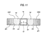
- Fig. 11 shows filter members bND1 and bND2 according to a third embodiment used in the light amount adjuster 2.
- Each of the filter members bND1 and bND2 has a gradation ND region gnd where the transmittance continuously changes, a lowest density region Ind where the transmittance is uniform and 80% or lower and a transparent region tra where the transmittance is uniform and at least 80%.
- the two filter members bND1 and bND2 are disposed such that they face each other and can symmetrically move with respect to each other.
- the transparent regions tra of the two filter members bND1 and bND2 overlap each other and cover the entire light path LD.
- one or both of the lowest density regions Ind of the filter members bND1 and bND2 are inserted into the light path LD and cover the entire light path LD, and then, the gradation ND regions gnd are symmetrically inserted into the light path LD from opposite positions in such a way that the ND density of the gradation ND region gnd in the light path gradually increases so as to attenuate the amount of transmitted light.
- the filter members bND1 and bND2 when the lowest density regions Ind are inserted into and removed from the light path LD, it is desirable to achieve programmed AE in which the F-number and/or the electronic shutter is set and at the same time the filter members bND1 and bND2 are moved according to the transition of subject brightness such that the borders dv1 and dv2 between the transparent regions tra and the lowest density regions Ind of the filter members bND1 and bND2 will not stop in the light path LD.
- Fig. 11 diagrammatically shows the state where the transparent regions tra of the filter members bND1 and bND2 cover the light path LD indicated by the broken line.
- the area from the border dv1 to the border dv2 is the uniform, lowest density region Ind, and there is a step having the thickness of the deposited film at the border dv1, which is the portion that causes phase difference.
- Fig. 12 diagrammatically shows how the lowest density regions Ind of the filter members bND1 and bND2 are inserted into the light path LD having the width A shown in Fig.
- Fig. 11 to cover the entire light path LD and then the gradation ND regions gnd are successively inserted from opposite positions in such a way that the low density region is first inserted, followed by higher density regions.
- Fig. 13 shows the distribution of ND density versus position in the width A of the light path LD.
- the numbers (1) to (8) labeled in the left part of Fig. 12 correspond to the numbers (1) to (8) labeled in the left part of Fig. 13.
- Figs. 11, 12 and 13 are expressed in a way similar to the way Figs. 2, 3 and 4 are expressed, respectively.
- the transparent regions tra of the two filter members bND1 and bND2 cover the light path LD, so that the highest transmittance is provided.
- the lowest density regions Ind are slightly inserted into the light path LD.
- the filter members bND1 and bND2 are configured such that they are inserted and removed in the vertical direction of the screen, the light at the upper and lower parts of the light path LD will be attenuated.
- part of the lowest density regions Ind of the two filter members bND1 and bND2 overlap each other at the center of the light path LD, so that the distribution of density versus position has a dark band at the center of the light path LD.
- the lowest density regions Ind of the two filter members bND1 and bND2 overlap each other, so that the density distribution becomes flat.
- the gradation ND regions gnd that follow the lowest density regions Ind are slightly inserted into the light path LD.
- the filter members bND1 and bND2 are configured such that they are inserted and removed in the vertical direction of the screen, the light at the upper and lower parts of the light path LD will be attenuated.
- the borders dv2 between the lowest density regions Ind and the gradation ND regions gnd of the two filter members bND1 and bND2 come into contact with each other at the center of the light path LD, so that the distribution of density versus position becomes a V-like shape.
- part of the gradation ND regions gnd overlap each other in the light path LD.
- the density distribution at the overlapping portion becomes flat.
- the lowest density regions Ind are completely retracted from the light path LD, so that the density distribution becomes flat across the light path LD.
- the two filter members bND1 and bND2 When the two filter members bND1 and bND2 are symmetrically moved with respect to each other until the highest density portions are inserted in the light path LD, the two filter members bND1 and bND2 provide the highest density 2D across the light path LD, where D is the density of one of the filter members bND1 and bND2 at the center of the light path LD.
- Combinations of the transmittance and the F-number of programmed AE in the imaging apparatus 1 having the light amount adjuster 2 using the filter members bND1 and bND2 are the same as those shown in Fig. 10.
- the aperture stop St formed of a plurality of diaphragm blades built in the lens L has a positional sensor and a drive device (not shown) that convey the F-number as positional information to a camera lens control circuit.
- the stop is driven based on a drive instruction signal from the camera lens control circuit.
- Such information is transmitted and driving power is supplied through an electric contact provided on the exchangeable lens mount Mt and a connection cable.
- the light amount adjuster 2 has a positional sensor and a drive device (not shown) that convey positional information on the filter members (ND1, ND2, aND1, aND2, bND1 and bND2) to the camera lens control circuit.
- the filter members are driven based on a drive instruction signal from the camera lens control circuit.
- the camera lens control circuit has, for example, a read-only memory, to which a programmed AE chart, for example, shown in Figs. 6 and 10, are recorded in advance.
- a point on the programmed AE chart is selected based on output signals from the imaging devices (GI, BI and RI) (based on brightness information on the subject), and the aperture stop and the light amount adjuster is set to the state specified by the selected point.
- Figs. 14 and 15 show embodiments of a drive mechanism that symmetrically moves the two filter members in the light amount adjuster 2.
- the filter members ND1 and ND2 shown in Fig. 2 are used.
- the two filter members ND1 and ND2 are disposed in a vertically symmetrical manner, and the filter members ND1 and ND2 is retained on filter retainers 2a and 2b, respectively, through bonding or the like.
- the filter retainers 2a and 2b are sandwiched and guided in a narrow space surrounded by two base plates (not shown) in such a way that the filter retainers have little play in the optical axis direction.
- Vertically elongated holes 2c and 2d provided in the filter retainers 2a and 2b engage guide pins (not shown) provided on the base plates, so that the filter retainers 2a and 2b are movably guided only in the vertical direction.
- the drive device Mo is a motor that is easily controlled, such as a stepper motor.
- connection pins 2f and 2g project from the tips of the rod Rd.
- the connection pins 2f and 2g engage elongated connection holes 2h and 2i that are elongated in the direction substantially perpendicular to the direction in which the elongated holes 2c and 2d in the filter retainers 2a and 2b extend, allowing power transmission.
- the rod Rd rotates and the ends of the rod Rd move in opposite directions.
- the connection pin 2f moves substantially downward, while the connection pin 2g moves substantially upward.
- the filter member ND1 moves downward, while the filter member ND2 moves upward. That is, the two filter members ND1 and ND2 will move in a symmetrical manner.
- the drive mechanism shown in Fig. 14 is expected to provide a stable motion similar to that obtained by using a galvanometric motor to drive diaphragm blades in a video camcorder of related art and the like.
- a problem of this mechanism is that the travel of the filter members ND1 and ND2 is longer than that of the diaphragm blades, resulting in an increased length of the rod Rd and hence an increased width of the light amount adjuster 2.
- the two filter members ND1 and ND2 are retained on filter retainers 2j and 2k, respectively.
- a drive pulley P1 is fixed to the output shaft 2e of the motor Mo described above.
- a driven pulley P2 is disposed on the opposite side to the drive pulley P1, for example, on the upper side.
- a belt Bt engages the two pulleys P1 and P2.
- Tension is applied to the driven pulley P2 by appropriate means (not shown), such as a spring, an elastic string and magnetic attractive force, in the direction away from the drive pulley P1 such that the belt Bt will not be loose.
- the filter retainers 2j and 2k are retained at the portions of the belt Bt that move in opposite directions.
- the imaging apparatus 1 described above can take various forms as a specific product.
- the imaging apparatus 1 can be broadly used as a camera unit of a video input/output apparatus, such as a digital video camcorder, a DVD video camcorder, a HDD video camcorder, a digital still camera and a surveillance video camcorder.
- the imaging apparatus according to the embodiment of the invention and the light amount adjuster according to the embodiment of the invention described above are specific examples for practicing the invention, and various types of manufacturing methods and density distribution of the gradation ND filters are conceivable.
- the aperture stop and the light amount adjuster can be integrated from the design point of view.
Landscapes
- Physics & Mathematics (AREA)
- General Physics & Mathematics (AREA)
- Engineering & Computer Science (AREA)
- Multimedia (AREA)
- Signal Processing (AREA)
- Optics & Photonics (AREA)
- Blocking Light For Cameras (AREA)
- Studio Devices (AREA)
- Exposure Control For Cameras (AREA)
- Optical Elements Other Than Lenses (AREA)
- Diaphragms For Cameras (AREA)
- Mechanical Light Control Or Optical Switches (AREA)
Applications Claiming Priority (1)
| Application Number | Priority Date | Filing Date | Title |
|---|---|---|---|
| JP2006117463A JP2007292828A (ja) | 2006-04-21 | 2006-04-21 | 光量調整装置及び撮像装置 |
Publications (2)
| Publication Number | Publication Date |
|---|---|
| EP1848202A2 true EP1848202A2 (fr) | 2007-10-24 |
| EP1848202A3 EP1848202A3 (fr) | 2007-12-26 |
Family
ID=38370355
Family Applications (1)
| Application Number | Title | Priority Date | Filing Date |
|---|---|---|---|
| EP07106526A Withdrawn EP1848202A3 (fr) | 2006-04-21 | 2007-04-19 | Ajusteur de quantité légère et appareil d'imagerie |
Country Status (6)
| Country | Link |
|---|---|
| US (1) | US20070248349A1 (fr) |
| EP (1) | EP1848202A3 (fr) |
| JP (1) | JP2007292828A (fr) |
| KR (1) | KR20070104233A (fr) |
| CN (1) | CN101059574A (fr) |
| TW (1) | TW200807142A (fr) |
Cited By (2)
| Publication number | Priority date | Publication date | Assignee | Title |
|---|---|---|---|---|
| EP2426554A1 (fr) * | 2009-04-30 | 2012-03-07 | JVC KENWOOD Corporation | Dispositif de contrôle de quantité de lumière, dispositif de prise de vues et procédé de contrôle de quantité de lumière |
| CN105814880A (zh) * | 2014-07-28 | 2016-07-27 | 联发科技股份有限公司 | 具有自适应全景图像处理器的便携式设备 |
Families Citing this family (22)
| Publication number | Priority date | Publication date | Assignee | Title |
|---|---|---|---|---|
| JP4732264B2 (ja) * | 2006-07-28 | 2011-07-27 | キヤノン株式会社 | 撮像装置 |
| JP5467326B2 (ja) * | 2008-09-11 | 2014-04-09 | パナソニック株式会社 | 光学フィルターを有する撮像装置 |
| JP2011248029A (ja) | 2010-05-26 | 2011-12-08 | Canon Inc | 光量調節装置および光学機器 |
| JP5731772B2 (ja) * | 2010-08-30 | 2015-06-10 | キヤノン株式会社 | 撮像装置及びその制御方法 |
| CN102402098B (zh) * | 2010-09-09 | 2014-03-26 | 株式会社尼康 | 可换透镜、相机主体及电子设备 |
| US8908081B2 (en) | 2010-09-09 | 2014-12-09 | Red.Com, Inc. | Optical filter opacity control for reducing temporal aliasing in motion picture capture |
| US8823829B2 (en) * | 2010-09-16 | 2014-09-02 | Canon Kabushiki Kaisha | Image capture with adjustment of imaging properties at transitions between regions |
| EP2511761A3 (fr) * | 2011-04-14 | 2014-08-27 | Canon Kabushiki Kaisha | Appareil de prise de vue et filtre à densité neutre |
| JP2013115635A (ja) * | 2011-11-29 | 2013-06-10 | Nippon Hoso Kyokai <Nhk> | 光学要素切替機構およびこれを備えた撮像装置 |
| JP6041503B2 (ja) * | 2012-03-13 | 2016-12-07 | 株式会社トプコン | 光量調整機構 |
| CN105264880B (zh) | 2013-04-05 | 2018-08-28 | Red.Com 有限责任公司 | 用于相机的滤光 |
| CN105432068B (zh) | 2013-08-01 | 2018-08-24 | 富士胶片株式会社 | 摄像装置、摄像方法及图像处理装置 |
| JP2016114831A (ja) * | 2014-12-16 | 2016-06-23 | 泓記精密股▲分▼有限公司 | フィルタ切り替え装置を備えた光学機器 |
| JP6727800B2 (ja) | 2015-03-05 | 2020-07-22 | キヤノン株式会社 | 光量調節装置、レンズ鏡筒、および光学装置 |
| US10021320B2 (en) * | 2016-06-28 | 2018-07-10 | Foveon, Inc. | Electronically controlled graduated density filters in stacked image sensors |
| WO2018100992A1 (fr) | 2016-11-29 | 2018-06-07 | ソニーセミコンダクタソリューションズ株式会社 | Système optique d'imagerie, module de caméra et appareil électronique |
| US10523885B2 (en) | 2016-12-20 | 2019-12-31 | Foveon, Inc. | Column line clamp circuit for imaging array |
| CN107682616B (zh) * | 2017-11-15 | 2019-10-29 | 维沃移动通信有限公司 | 控制方法、摄像头盖板和移动终端 |
| WO2019171723A1 (fr) * | 2018-03-06 | 2019-09-12 | ソニー株式会社 | Dispositif d'imagerie et unite d'imagerie |
| WO2019172437A1 (fr) * | 2018-03-09 | 2019-09-12 | 富士フイルム株式会社 | Dispositif de commande d'imagerie, dispositif d'imagerie, procédé de commande d'imagerie, et programme de commande d'imagerie |
| JP2020181125A (ja) * | 2019-04-26 | 2020-11-05 | 日本放送協会 | フィルタ光学系およびこれを用いた撮像装置 |
| JP2023106138A (ja) * | 2022-01-20 | 2023-08-01 | パナソニックIpマネジメント株式会社 | 撮像装置 |
Citations (5)
| Publication number | Priority date | Publication date | Assignee | Title |
|---|---|---|---|---|
| JPH05281592A (ja) * | 1992-03-31 | 1993-10-29 | Sony Corp | 撮影レンズの絞り装置 |
| WO1993024786A1 (fr) * | 1992-05-22 | 1993-12-09 | Panavision International, L.P. | Systeme de variation d'intensite lumineuse utilise notamment en prise de vue cinematographique |
| JP2003315870A (ja) * | 2002-02-19 | 2003-11-06 | Canon Inc | 光量調節装置 |
| JP2004020711A (ja) * | 2002-06-13 | 2004-01-22 | Canon Inc | 光量調節装置及び撮影装置 |
| US6771315B1 (en) * | 1998-07-31 | 2004-08-03 | Sony Corporation | Image pickup apparatus |
Family Cites Families (4)
| Publication number | Priority date | Publication date | Assignee | Title |
|---|---|---|---|---|
| US5387958A (en) * | 1992-06-30 | 1995-02-07 | Sony Electronics, Inc. | Electro-optical control of light attenuation in the optical path of a camera |
| JP4508521B2 (ja) * | 2002-07-16 | 2010-07-21 | オリンパス株式会社 | 撮像装置 |
| US7042662B2 (en) * | 2002-12-26 | 2006-05-09 | Canon Kabushiki Kaisha | Light amount adjusting device, and optical device using the light amount adjusting device |
| JP2005321545A (ja) * | 2004-05-07 | 2005-11-17 | Sony Corp | 撮像装置 |
-
2006
- 2006-04-21 JP JP2006117463A patent/JP2007292828A/ja active Pending
-
2007
- 2007-04-13 TW TW096113084A patent/TW200807142A/zh unknown
- 2007-04-16 KR KR1020070036780A patent/KR20070104233A/ko not_active Application Discontinuation
- 2007-04-18 US US11/788,006 patent/US20070248349A1/en not_active Abandoned
- 2007-04-19 EP EP07106526A patent/EP1848202A3/fr not_active Withdrawn
- 2007-04-23 CN CNA2007100966835A patent/CN101059574A/zh active Pending
Patent Citations (5)
| Publication number | Priority date | Publication date | Assignee | Title |
|---|---|---|---|---|
| JPH05281592A (ja) * | 1992-03-31 | 1993-10-29 | Sony Corp | 撮影レンズの絞り装置 |
| WO1993024786A1 (fr) * | 1992-05-22 | 1993-12-09 | Panavision International, L.P. | Systeme de variation d'intensite lumineuse utilise notamment en prise de vue cinematographique |
| US6771315B1 (en) * | 1998-07-31 | 2004-08-03 | Sony Corporation | Image pickup apparatus |
| JP2003315870A (ja) * | 2002-02-19 | 2003-11-06 | Canon Inc | 光量調節装置 |
| JP2004020711A (ja) * | 2002-06-13 | 2004-01-22 | Canon Inc | 光量調節装置及び撮影装置 |
Cited By (5)
| Publication number | Priority date | Publication date | Assignee | Title |
|---|---|---|---|---|
| EP2426554A1 (fr) * | 2009-04-30 | 2012-03-07 | JVC KENWOOD Corporation | Dispositif de contrôle de quantité de lumière, dispositif de prise de vues et procédé de contrôle de quantité de lumière |
| EP2426554A4 (fr) * | 2009-04-30 | 2012-12-19 | Jvc Kenwood Corp | Dispositif de contrôle de quantité de lumière, dispositif de prise de vues et procédé de contrôle de quantité de lumière |
| US8934031B2 (en) | 2009-04-30 | 2015-01-13 | JVC Kenwood Corporation | Light intensity control device, imaging device and light intensity control method |
| CN105814880A (zh) * | 2014-07-28 | 2016-07-27 | 联发科技股份有限公司 | 具有自适应全景图像处理器的便携式设备 |
| US10419668B2 (en) | 2014-07-28 | 2019-09-17 | Mediatek Inc. | Portable device with adaptive panoramic image processor |
Also Published As
| Publication number | Publication date |
|---|---|
| US20070248349A1 (en) | 2007-10-25 |
| JP2007292828A (ja) | 2007-11-08 |
| TW200807142A (en) | 2008-02-01 |
| CN101059574A (zh) | 2007-10-24 |
| KR20070104233A (ko) | 2007-10-25 |
| EP1848202A3 (fr) | 2007-12-26 |
Similar Documents
| Publication | Publication Date | Title |
|---|---|---|
| EP1848202A2 (fr) | Ajusteur de quantité légère et appareil d'imagerie | |
| JP3950707B2 (ja) | 光学機器 | |
| JP6422942B2 (ja) | カメラ用光学的フィルタリング | |
| US7113318B2 (en) | Light amount control apparatus, photographing apparatus, and filter | |
| US8079764B2 (en) | Light quantity adjusting device, lens barrel, image pickup device, and method of controlling the image pickup device | |
| US7253839B2 (en) | Electronic camera | |
| KR101760347B1 (ko) | 디지털 촬영 장치 및 이의 제어 방법 | |
| CN104488256B (zh) | 照相机及其动作控制方法 | |
| US8760556B2 (en) | Image capture apparatus with variable translucency mirror | |
| CN102422215A (zh) | 光量控制装置、摄影装置以及光量控制方法 | |
| JP2006311060A (ja) | 撮像装置及びデジタルカメラ | |
| JP4684386B2 (ja) | 光量調節装置および光学機器 | |
| CN108141515B (zh) | 摄影装置及其控制方法 | |
| JP4833129B2 (ja) | デジタルカメラ及びオートフォーカス装置 | |
| JP2010152405A (ja) | 光学機器及び光量調節装置 | |
| JP2004333553A (ja) | 光量調節装置、撮影装置及びフィルタ | |
| JP4200270B2 (ja) | 光量調整装置、レンズ鏡筒、撮像装置 | |
| JP2010102044A (ja) | 光量調整装置、レンズ鏡筒、及び撮像装置 | |
| JP4217325B2 (ja) | 光量調節装置 | |
| JP3976893B2 (ja) | 光量調整装置及び光量調整方法 | |
| JP2006208568A (ja) | 撮像装置、光量調節機構及び光量制御フィルター | |
| JP4194361B2 (ja) | 光学機器 | |
| JP2008040084A (ja) | 光学装置 | |
| JP2002156607A (ja) | 撮像装置 | |
| JP2003315871A (ja) | Nd駆動装置、及びそれを有する撮像装置 |
Legal Events
| Date | Code | Title | Description |
|---|---|---|---|
| PUAI | Public reference made under article 153(3) epc to a published international application that has entered the european phase |
Free format text: ORIGINAL CODE: 0009012 |
|
| AK | Designated contracting states |
Kind code of ref document: A2 Designated state(s): AT BE BG CH CY CZ DE DK EE ES FI FR GB GR HU IE IS IT LI LT LU LV MC MT NL PL PT RO SE SI SK TR |
|
| AX | Request for extension of the european patent |
Extension state: AL BA HR MK YU |
|
| PUAL | Search report despatched |
Free format text: ORIGINAL CODE: 0009013 |
|
| AK | Designated contracting states |
Kind code of ref document: A3 Designated state(s): AT BE BG CH CY CZ DE DK EE ES FI FR GB GR HU IE IS IT LI LT LU LV MC MT NL PL PT RO SE SI SK TR |
|
| AX | Request for extension of the european patent |
Extension state: AL BA HR MK YU |
|
| 17P | Request for examination filed |
Effective date: 20080617 |
|
| 17Q | First examination report despatched |
Effective date: 20080721 |
|
| AKX | Designation fees paid |
Designated state(s): DE FR GB |
|
| STAA | Information on the status of an ep patent application or granted ep patent |
Free format text: STATUS: THE APPLICATION IS DEEMED TO BE WITHDRAWN |
|
| 18D | Application deemed to be withdrawn |
Effective date: 20081202 |