EP1844520B1 - Glass pane with a retaining socket - Google Patents
Glass pane with a retaining socket Download PDFInfo
- Publication number
- EP1844520B1 EP1844520B1 EP06706356A EP06706356A EP1844520B1 EP 1844520 B1 EP1844520 B1 EP 1844520B1 EP 06706356 A EP06706356 A EP 06706356A EP 06706356 A EP06706356 A EP 06706356A EP 1844520 B1 EP1844520 B1 EP 1844520B1
- Authority
- EP
- European Patent Office
- Prior art keywords
- glass pane
- retaining
- base part
- built
- accommodation space
- Prior art date
- Legal status (The legal status is an assumption and is not a legal conclusion. Google has not performed a legal analysis and makes no representation as to the accuracy of the status listed.)
- Active
Links
- 239000011521 glass Substances 0.000 title claims abstract description 130
- 230000004308 accommodation Effects 0.000 claims description 84
- 230000005291 magnetic effect Effects 0.000 claims description 6
- 238000004026 adhesive bonding Methods 0.000 claims description 3
- 239000000853 adhesive Substances 0.000 abstract description 17
- 230000001070 adhesive effect Effects 0.000 abstract description 17
- 238000009434 installation Methods 0.000 abstract description 4
- 230000014759 maintenance of location Effects 0.000 description 10
- 238000005476 soldering Methods 0.000 description 7
- 239000000463 material Substances 0.000 description 5
- 229920003023 plastic Polymers 0.000 description 5
- 238000003466 welding Methods 0.000 description 5
- 239000004033 plastic Substances 0.000 description 4
- 238000000034 method Methods 0.000 description 3
- 229920001707 polybutylene terephthalate Polymers 0.000 description 3
- 229910000679 solder Inorganic materials 0.000 description 3
- 238000006073 displacement reaction Methods 0.000 description 2
- 238000005516 engineering process Methods 0.000 description 2
- 239000003365 glass fiber Substances 0.000 description 2
- 238000004519 manufacturing process Methods 0.000 description 2
- 229910052751 metal Inorganic materials 0.000 description 2
- 239000002184 metal Substances 0.000 description 2
- 150000002739 metals Chemical class 0.000 description 2
- 230000008439 repair process Effects 0.000 description 2
- FYYHWMGAXLPEAU-UHFFFAOYSA-N Magnesium Chemical compound [Mg] FYYHWMGAXLPEAU-UHFFFAOYSA-N 0.000 description 1
- BQCADISMDOOEFD-UHFFFAOYSA-N Silver Chemical compound [Ag] BQCADISMDOOEFD-UHFFFAOYSA-N 0.000 description 1
- 229910045601 alloy Inorganic materials 0.000 description 1
- 239000000956 alloy Substances 0.000 description 1
- 230000005540 biological transmission Effects 0.000 description 1
- 239000000969 carrier Substances 0.000 description 1
- 238000005266 casting Methods 0.000 description 1
- 239000004020 conductor Substances 0.000 description 1
- 238000001514 detection method Methods 0.000 description 1
- 238000011161 development Methods 0.000 description 1
- 230000018109 developmental process Effects 0.000 description 1
- 230000000694 effects Effects 0.000 description 1
- 230000005294 ferromagnetic effect Effects 0.000 description 1
- 239000003292 glue Substances 0.000 description 1
- 238000010438 heat treatment Methods 0.000 description 1
- 238000001746 injection moulding Methods 0.000 description 1
- 238000003780 insertion Methods 0.000 description 1
- 230000037431 insertion Effects 0.000 description 1
- 239000005340 laminated glass Substances 0.000 description 1
- 229910052749 magnesium Inorganic materials 0.000 description 1
- 239000011777 magnesium Substances 0.000 description 1
- 230000003287 optical effect Effects 0.000 description 1
- 239000002245 particle Substances 0.000 description 1
- -1 polybutylene terephthalate Polymers 0.000 description 1
- 229920001296 polysiloxane Polymers 0.000 description 1
- 229910052709 silver Inorganic materials 0.000 description 1
- 239000004332 silver Substances 0.000 description 1
- 239000000243 solution Substances 0.000 description 1
- 239000000758 substrate Substances 0.000 description 1
Images


Classifications
-
- H—ELECTRICITY
- H01—ELECTRIC ELEMENTS
- H01Q—ANTENNAS, i.e. RADIO AERIALS
- H01Q1/00—Details of, or arrangements associated with, antennas
- H01Q1/12—Supports; Mounting means
- H01Q1/1271—Supports; Mounting means for mounting on windscreens
-
- H—ELECTRICITY
- H01—ELECTRIC ELEMENTS
- H01R—ELECTRICALLY-CONDUCTIVE CONNECTIONS; STRUCTURAL ASSOCIATIONS OF A PLURALITY OF MUTUALLY-INSULATED ELECTRICAL CONNECTING ELEMENTS; COUPLING DEVICES; CURRENT COLLECTORS
- H01R13/00—Details of coupling devices of the kinds covered by groups H01R12/70 or H01R24/00 - H01R33/00
- H01R13/73—Means for mounting coupling parts to apparatus or structures, e.g. to a wall
-
- H—ELECTRICITY
- H01—ELECTRIC ELEMENTS
- H01R—ELECTRICALLY-CONDUCTIVE CONNECTIONS; STRUCTURAL ASSOCIATIONS OF A PLURALITY OF MUTUALLY-INSULATED ELECTRICAL CONNECTING ELEMENTS; COUPLING DEVICES; CURRENT COLLECTORS
- H01R2201/00—Connectors or connections adapted for particular applications
- H01R2201/02—Connectors or connections adapted for particular applications for antennas
-
- H—ELECTRICITY
- H01—ELECTRIC ELEMENTS
- H01R—ELECTRICALLY-CONDUCTIVE CONNECTIONS; STRUCTURAL ASSOCIATIONS OF A PLURALITY OF MUTUALLY-INSULATED ELECTRICAL CONNECTING ELEMENTS; COUPLING DEVICES; CURRENT COLLECTORS
- H01R2201/00—Connectors or connections adapted for particular applications
- H01R2201/26—Connectors or connections adapted for particular applications for vehicles
Definitions
- the invention relates to glass panes, in particular automotive glass panes, with built-in components detachably fixed thereto with the aid of retaining sockets, and to retaining sockets for the same.
- Glass panes and in particular automotive glass panes are being equipped with an ever-increasing diversity of functions, which as a rule are made available by means of built-in parts connected permanently or detachably to the glass pane.
- functions are the reception and transmission of electromagnetic signals with the aid of antennas for frequency ranges in the kHz range up to the GHz range, the detection of ambient conditions or of signals with the aid of sensors such as rain, temperature or light sensors, the emission of light with the aid of brake or signal lights, the use of glass panes as carriers of devices such as mirrors using mirror bosses, and many more.
- the built-in parts to be affixed in this regard to the glass panes comprise elements such as, for example, antennas, electronic components such as for example antenna amplifiers, terminals or connectors, brake lights in the form of individual lights or light clusters, optical or electrical rain sensors and many others.
- the projections are designed either as guide rails disposed on three sides, which permit the high-frequency device to be pushed into the accommodation space parallel to the surface of the glass pane, or they are perforated.
- the high-frequency device is first introduced perpendicular to the glass pane into the accommodation space of the frame-like retaining socket and then pushed slightly to the side in the latter for the purpose of fixing.
- the high frequency device is equipped with spring contacts, which at the same time as the fixing of the high-frequency device make contact in a detachable manner with the contacting points on the glass pane inside the frame-like retaining socket.
- the previously known retaining socket is intended solely for the fixing of built-in parts such as antenna amplifiers to glass panes and is designed comparatively complex and costly, and on the other hand offers little flexibility of use.
- EP-A-0 506 451 discloses the features of the preamble of independent claim 1.
- the retaining socket according to the invention is defined by claim 1.
- the base part is used for the fixing, in particular gluing, of the retaining socket to the glass pane.
- the description below mainly refers to this first embodiment. It is in many respects however also readable onto a more general aspect of the invention, wherein the base part primarily serves to provide a reference plane and support function common to both accommodation spaces and wherein the retaining socket may alternatively be attached to the glass pane via side walls and/or side supports such as described and explained herein later.
- the provision of the two different accommodation spaces makes it possible to use the same retaining socket for different fixing directions when fitting a built-in part.
- An individual retaining socket needs to have only comparatively small dimensions, since a number of retaining sockets can be disposed spaced apart from one another on the glass pane for the fixing of built-in parts with larger dimensions, whereby a retaining socket is assigned respectively to a retaining portion of the built-in part.
- the accommodation spaces are designed in such a way that a suitably shaped retaining portion can be accommodated therein and fixed detachably therein in the intended retention position.
- the fixing means assigned to an accommodation space can be disposed in the respective accommodation space or outside the latter.
- the accommodation spaces normally comprise guide elements such as rails or walls, so that the introduced retaining portion can be guided into the retention position according to the intended direction of movement and held therein.
- the first accommodation space is preferably constructed tank-shaped or channel-shaped, i.e. is open at the top viewed from the glass pane and thus permits the introduction of the corresponding retaining portion from above, i.e. essentially perpendicular to the glass pane.
- the second accommodation space is preferably constructed tunnel-shaped or bridge-shaped, i.e. it has at all events a cover bar facing away from the glass pane, which prevents a retaining portion of the built-in part introduced into this accommodation space from moving away from the glass pane and thus mechanically secures the latter in the direction of movement perpendicular to the glass pane.
- the first accommodation space permits the introduction of the corresponding retaining portion essentially perpendicular to the base part which may be arranged parallel or perpendicular to the glass pane
- the second accommodation space is preferably constructed tunnel-shaped or bridge-shaped, i.e. it has at all events a cover bar facing away from the base part, which prevents a retaining portion of the built-in part introduced into this accommodation space from moving away perpendicular to the base part and thus mechanically secures the latter to the glass pane.
- the retaining socket preferably has at least two side walls disposed on the base part and - in its first embodiment - on its side facing away from the glass pane which run perpendicular to said base part (and optionally the glass pane), said side walls enclosing between them the first accommodation space.
- the side walls at least partially enclose between them the assigned retaining portion of the built-in part introduced into the first accommodation space.
- the retaining portion of the built-in part can be designed higher or lower than the side walls. It can in particular also continue beyond the first accommodation space, so that the side walls and in particular their upper edges are enclosed on both sides at least in zones by the retaining portion.
- the fixing element can preferably comprise at least one lock-in ridge running parallel to the base part.
- Lock-in ridge means an extended protrusion of at least one of the side walls, which either engages in an assigned recess of the retaining portion or grips over the retaining portion after the retention position has been reached.
- a lock-in ridge can also be designed as a notch or groove in a side wall, into which an extended protrusion disposed in the retaining portion can engage.
- lock-in ridges are provided in the area of the side walls, this also facilitates pushing-in of a retaining portion of the built-in part parallel to the glass pane or more generally to the base part, into the first accommodation space as a further variant of the fixing of a built-in part with the aid of the retaining socket according to the invention.
- the lock-in ridges act as guide rails for the retaining portion.
- the removal of the built-in part takes place by releasing the lock-in connection, for which purpose suitable tools can be used in a known manner.
- the retaining socket can be equipped if need be with auxiliary means, with which the removal of the built-in part is facilitated.
- the base part preferably has at least one through-hole disposed between the side walls, which through-hole enables a direct contact of the built-in part fixed in the retaining socket or more precisely contacts disposed thereon, especially spring contacts, with the glass pane or contacting points located thereon.
- the through-hole extending at right angles to the base part or to the glass pane is surrounded all round by the base part, in particular for stability reasons.
- the base part prefferably comprises separate adhesion flanges adjacent to the side walls, by means of which the retaining socket is glued to the glass pane.
- a soldered joint or the like can also be made in the region of the adhesion flange.
- the retaining socket may be affixed to the glass panes via other surfaces, e.g., via its side walls, which in this case need then to be configured such as described before in the context of the base part.
- the retaining socket according to the invention comprises at least one bridge, which together with the base part or (in the installed state of the first embodiment) with the glass pane forms the second, tunnel-like accommodation space, the bridge following on, especially in the longitudinal direction of the side walls, directly from the latter or with a spacing.
- the second accommodation space if there is provided in the region of the bridge at least one fixing element, with which a retaining portion of the built-in part can be fixed in the second accommodation space, so that undesired detachment or displacement of the retaining portion of the built-in part introduced therein is prevented after the retention position has been reached.
- the fixing element comprises at least one lock-in ridge along the cover bar and/or one of the side supports (as a rule disposed perpendicular to the base part or the glass pane) of the bridge.
- the retaining socket comprises at least one magnetic guidance or fixing element, which can be disposed for example in the region of one of the accommodation spaces.
- this magnetic guidance or fixing element can be assigned to this magnetic guidance or fixing element at least one corresponding magnet or one ferromagnetic counterpart in the region of the retaining portion of the built-in part to be fixed thereto, so that the retaining portion is either guided by magnetic repulsion during the introduction into the respective accommodation space of the retaining socket or - in the case of opposite-pole magnets - is drawn into the retaining socket by magnetic attraction and is fixed in the retention position.
- This variant of the invention can facilitate and make more reliable the fixing of the built-in part at the intended place and in the desired orientation.
- the invention also relates to a glass pane, in particular an automotive glass pane, with at least one retaining socket according to the invention fixed to the latter.
- An individual retaining socket will as a rule suffice to fix smaller built-in parts to the glass pane, for example electrical plug-in connectors.
- at least two of the retaining sockets according to the invention will as a rule be used, the universality of the retaining socket taking effect especially when one of the retaining portions is introduced parallel to the base part (to the glass pane) into the corresponding accommodation space of the assigned retaining socket and another is introduced perpendicular to the base part (to the glass pane) into the other accommodation space of a retaining socket of the same design.
- a particularly preferred application of the invention is an arrangement consisting of a glass pane and at least one retaining socket; wherein a retaining socket comprises a through-hole, e.g. in its base part, in which is disposed at least one contacting point of an electrical arrangement on the glass pane, the built-in part comprising at least one spring contact assigned to this contacting point.
- the retaining socket according to the invention can be produced from a large variety of materials. Not only from the cost standpoint is it particularly preferably made from plastic. It can be produced in particular as a one-piece component, in particular by injection moulding.
- the plastic should have a thermal expansion coefficient that does not differ too far from that of the glass pane, in order to avoid a thermally induced detachment of the retaining socket from the glass pane.
- glass-fibre reinforced polybutylene terephthalate (PBT) with a glass fibre proportion of up to approx. 50 vol.% (PBT GF 50) is regarded as a particularly suitable material.
- metals such as for example magnesium or its alloys, or other materials can be used for the production of the retaining socket according to the invention, especially metals mouldable in the casting process.
- Two retaining sockets 3 are fixed to glass pane 1 close to its upper pane edge, to which retaining sockets 3 a built-in part 2 is fixed detachably with retaining portions 4.
- Built-in part 2 could for example be a brake light, a rain sensor, an antenna or an antenna amplifier.
- Built-in part 2 is supplied, for example, with energy via these supply lines 22 after the fixing in retaining sockets 3 or signals are routed from built-in part 2 to a receiver on the vehicle side or from a transmitter on the vehicle side into built-in part 2.
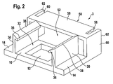
- Retaining socket 3 has a two-dimensionally extending base part 10, the underside whereof is intended for fixing to a glass pane 1 not shown here. Disposed on base part 10 and perpendicular thereto are two side walls 30 spaced apart from one another, which between them enclose a first accommodation space 32 for accommodating a retaining portion 4 (not shown here) of a built-in part 2. First accommodation space 32 is open to the top, so that retaining portion 4 can be introduced into it perpendicular to base part 10 and parallel to side walls 30.
- Base part 10 has between side walls 30 a through-hole 12 extending perpendicular to base part 10, via which through-hole 12 direct contact can be made between retaining portion 4 of built-in part 2 and glass pane 1 or contacting points 20 located thereon.
- base part 10 comprises two adhesion flanges 14 which, viewed from first accommodation space 32, lie externally adjacent to side walls 30.
- Adhesion flanges 14 can be provided on their undersides with an adhesive, they can also comprise adhesive chambers open to the bottom, in which the adhesive is disposed with which retaining socket 3 is glued to glass pane 1.
- the whole underside of base part 10 or a part thereof forms the adhesion surface.
- another kind of mechanical, permanent connection to glass pane 1 could also take place, e.g. by soldering, welding or the like, where, for example, solder deposits or suchlike can be provided instead of an adhesive.
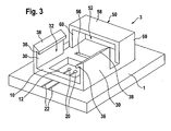
- the inside width of bridge 50 is greater than the distance between side walls 30 of first accommodation space 32 in the first embodiment ( figure 2 ) and is equal to the latter in the second embodiment ( figure 3 ). It could also be smaller. Similarly, the height and the length of the two accommodation spaces 32, 52 could in each case be equal to or different from one another.
- Tunnel-like second accommodation space 52 could also be designed as a through-hole in a transverse wall, which follows on from side walls 30 directly or with a spacing, said through-hole extending parallel to base part 10.
- cover bar 58 of bridge 50 has a middle segment, which is separated by oblong notches from its end zones.
- the middle segment of cover bar 58 is equipped with a fixing element 56 in the form of a lock-in ridge. Due to the provision of the notches, it is able to become elastically deformed more easily than without the notches during the insertion of assigned retaining portion 4 and can move back after the retention position has been reached with the lock-in ridge locking into an assigned lock-in groove in retaining portion 4.
- Side supports 60 and cover bar 58 of bridge 50 serve to guide and hold a retaining portion 4 of built-in part 2 introduced parallel to base part 10 and glass pane 1 into second accommodation space 52 and at the same time stiffen retaining socket 3.
- outer edges 62 of the bridge could also be bevelled similar to outer edges 38 of the side walls, in order to facilitate the pushing-in of a retaining portion 4 beneath bridge 50.
- Figure 2 shows bevelling of the middle part of cover bar 58 with the same purpose.
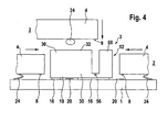
- a retaining socket 3 according to figures 2 , 3 fixed to a glass pane 1 by means of an adhesive 16 is shown in side view in figure 4 .
- Three movement variants are shown as to how a retaining portion 4 of a built-in part 2 can be introduced into retaining socket 3, i.e. parallel to glass pane 1 and to base part 10 from the left into first accommodation space 32, from above perpendicular to base part 10 into first accommodation space 32, and finally from the right parallel to glass pane 1 and to base part 10 into second accommodation space 52.
- Retaining portions 4 each have on their underside a fixing means 8 designed as a locking lug, which is intended to lock into an assigned fixing means 56 (lock-in groove) of retaining socket 3 (see also figure 3 ) in the final retention position, so that an undesired movement parallel to glass pane 1 is prevented.
- Built-in part 2 has at its lower side a spring contact 24 which, after fixing in retaining sockets 3, is in an electrically conductive connection with a contacting point 20, from which a supply line 22 proceeds, which leads to an electrical arrangement (not shown) on glass pane 1.
- the electrical contact location is disposed close to left-hand retaining socket 3, in order that cover bar 58 of bridge 50 of tunnel-like accommodation space 52 can absorb reliably and durably the permanently acting elastic force of spring contact 24 in the installed state.
- retaining sockets 3 are disposed in such a way that their accommodation spaces 32 point towards one another.
- built-in part 2 is introduced from above in the direction of movement perpendicular to glass pane 1 with its retaining portions 4 into accommodation spaces 32 of retaining sockets 3 and detachably fixed therein.
- U-shaped built-in part 2 has retaining portions 4 projecting at an angle.
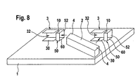
- the two retaining sockets 3 are fixed parallel and at a distance from one another on glass pane 1, in such a way that accommodation spaces 52 each point forwards.
- built-in part 2 is moved from front to back for the fixing, whereby its retaining portions 4 slide into tunnel-like accommodation spaces 52 and are fixed detachably therein.
- the base part 10 of the retaining socket 3 is fixed to a glass pane 1, for example by soldering or friction welding, but especially by an adhesive joint.
- the retaining socket 3 may instead be fixed to the glass pane 1 using a side wall 30 of the first accommodation space 32 and/or a side support 60 of the bridge 50.
- the side wall 30 and/or side support 60 may be fixed to the glass by, for example, soldering or friction welding, but especially by an adhesive joint.
- a built-in part 2 is lowered near to a first retaining socket 3, arranged on the left side of Fig.
Landscapes
- Securing Of Glass Panes Or The Like (AREA)
- Connection Of Plates (AREA)
- Connecting Device With Holders (AREA)
- Supports Or Holders For Household Use (AREA)
- Clamps And Clips (AREA)
- Load-Bearing And Curtain Walls (AREA)
- Window Of Vehicle (AREA)
Priority Applications (1)
| Application Number | Priority Date | Filing Date | Title |
|---|---|---|---|
| PL06706356T PL1844520T3 (pl) | 2005-01-24 | 2006-01-23 | Szyba szklana z gniazdem zatrzymującym |
Applications Claiming Priority (2)
| Application Number | Priority Date | Filing Date | Title |
|---|---|---|---|
| DE102005003386A DE102005003386B3 (de) | 2005-01-24 | 2005-01-24 | Haltesockel zur lösbaren Befestigung eines Einbauteils an einer Glasscheibe |
| PCT/EP2006/000551 WO2006077149A1 (en) | 2005-01-24 | 2006-01-23 | Retaining socket |
Publications (2)
| Publication Number | Publication Date |
|---|---|
| EP1844520A1 EP1844520A1 (en) | 2007-10-17 |
| EP1844520B1 true EP1844520B1 (en) | 2008-08-13 |
Family
ID=36118191
Family Applications (1)
| Application Number | Title | Priority Date | Filing Date |
|---|---|---|---|
| EP06706356A Active EP1844520B1 (en) | 2005-01-24 | 2006-01-23 | Glass pane with a retaining socket |
Country Status (10)
| Country | Link |
|---|---|
| US (1) | US7780454B2 (pl) |
| EP (1) | EP1844520B1 (pl) |
| JP (1) | JP4700070B2 (pl) |
| CN (1) | CN101120481B (pl) |
| AT (1) | ATE405000T1 (pl) |
| BR (1) | BRPI0606503B1 (pl) |
| DE (2) | DE102005003386B3 (pl) |
| ES (1) | ES2311276T3 (pl) |
| PL (1) | PL1844520T3 (pl) |
| WO (1) | WO2006077149A1 (pl) |
Families Citing this family (26)
| Publication number | Priority date | Publication date | Assignee | Title |
|---|---|---|---|---|
| US6124886A (en) | 1997-08-25 | 2000-09-26 | Donnelly Corporation | Modular rearview mirror assembly |
| US6326613B1 (en) | 1998-01-07 | 2001-12-04 | Donnelly Corporation | Vehicle interior mirror assembly adapted for containing a rain sensor |
| US8288711B2 (en) | 1998-01-07 | 2012-10-16 | Donnelly Corporation | Interior rearview mirror system with forwardly-viewing camera and a control |
| US6445287B1 (en) | 2000-02-28 | 2002-09-03 | Donnelly Corporation | Tire inflation assistance monitoring system |
| US6278377B1 (en) | 1999-08-25 | 2001-08-21 | Donnelly Corporation | Indicator for vehicle accessory |
| US6420975B1 (en) | 1999-08-25 | 2002-07-16 | Donnelly Corporation | Interior rearview mirror sound processing system |
| US7480149B2 (en) | 2004-08-18 | 2009-01-20 | Donnelly Corporation | Accessory module for vehicle |
| WO2001064481A2 (en) | 2000-03-02 | 2001-09-07 | Donnelly Corporation | Video mirror systems incorporating an accessory module |
| US6396408B2 (en) | 2000-03-31 | 2002-05-28 | Donnelly Corporation | Digital electrochromic circuit with a vehicle network |
| US6824281B2 (en) | 2002-01-31 | 2004-11-30 | Donnelly Corporation | Vehicle accessory module |
| WO2006063827A1 (en) | 2004-12-15 | 2006-06-22 | Magna Donnelly Electronics Naas Limited | An accessory module system for a vehicle window |
| GB0624201D0 (en) * | 2006-12-04 | 2007-01-10 | Pilkington Automotive D Gmbh | Connector |
| GB0702938D0 (en) | 2007-02-15 | 2007-03-28 | Pilkington Automotive D Gmbh | Retaining socket for automotive glazing |
| DE102007014534A1 (de) * | 2007-03-27 | 2008-10-02 | Leopold Kostal Gmbh & Co. Kg | Dachintegrationsmodul |
| DE102007026460B4 (de) * | 2007-06-05 | 2023-02-23 | Volkswagen Ag | Befestigungsanordnung für eine Elektronikkomponente in einem Fahrzeug |
| DE102008011806B3 (de) | 2008-02-29 | 2009-09-24 | Yamaichi Electronics Deutschland Gmbh | Verbindersystem, Verwendung, Verfahren, Verbinderhalteeinrichtung und Verbinder |
| DE102008044840A1 (de) * | 2008-08-28 | 2010-03-04 | Leopold Kostal Gmbh & Co. Kg | Sensoranordnung für ein Kraftfahrzeug |
| DE102008044839A1 (de) | 2008-08-28 | 2010-03-04 | Leopold Kostal Gmbh & Co. Kg | Sensoranordnung für ein Kraftfahrzeug |
| US8570374B2 (en) | 2008-11-13 | 2013-10-29 | Magna Electronics Inc. | Camera for vehicle |
| JP5972716B2 (ja) * | 2012-09-03 | 2016-08-17 | 小島プレス工業株式会社 | 車両ウィンドウ用アンプ装置 |
| US12068231B2 (en) * | 2014-05-24 | 2024-08-20 | Broadpak Corporation | 3D integrations and methods of making thereof |
| DE102016006775A1 (de) * | 2016-06-02 | 2017-12-07 | Rosenberger Hochfrequenztechnik Gmbh & Co. Kg | Elektrische Steckverbindung |
| CN107984983A (zh) * | 2017-11-24 | 2018-05-04 | 广东菲柯特电子科技有限公司 | 一种悬挂式胎压仪 |
| FR3086410B1 (fr) * | 2018-09-24 | 2020-12-11 | Alstom Transp Tech | Interface usb destinee a equiper un vehicule de transport public |
| KR20220106130A (ko) * | 2019-12-03 | 2022-07-28 | 에이지씨 가부시키가이샤 | 스페이서를 구비한 안테나 유닛 및 안테나 유닛을 구비한 유리창 |
| JP2025504655A (ja) | 2022-01-26 | 2025-02-14 | ピルキントン グループ リミテッド | センサブラケットグレージング |
Family Cites Families (17)
| Publication number | Priority date | Publication date | Assignee | Title |
|---|---|---|---|---|
| FR2132920A5 (pl) | 1971-04-01 | 1972-11-24 | Cipa | |
| FR2210958A6 (pl) | 1972-12-19 | 1974-07-12 | Cipa | |
| JPS5637338Y2 (pl) * | 1977-11-09 | 1981-09-01 | ||
| JPH032709U (pl) * | 1989-05-29 | 1991-01-11 | ||
| US5035635A (en) * | 1990-09-04 | 1991-07-30 | Tsai Shiang Shiun | Revolving safety socket |
| JPH082926Y2 (ja) * | 1991-03-29 | 1996-01-29 | 日本板硝子株式会社 | アンテナコネクタ |
| JPH0575981U (ja) * | 1992-03-18 | 1993-10-15 | 矢崎総業株式会社 | ガラス板用コネクタ |
| FR2717011B1 (fr) * | 1994-03-02 | 1996-03-29 | Telemecanique | Conecteur pour canalisation électrique. |
| FR2739333B1 (fr) * | 1995-09-29 | 1997-11-14 | Valeo Systemes Dessuyage | Essuie-glace muni d'un deflecteur souple fixe sur des griffes de fixation de la raclette d'essuyage |
| DE19633933A1 (de) * | 1996-08-22 | 1998-04-02 | Gore W L & Ass Gmbh | Bandkabel-Verbinder |
| US6234820B1 (en) * | 1997-07-21 | 2001-05-22 | Rambus Inc. | Method and apparatus for joining printed circuit boards |
| US5898183A (en) * | 1997-10-16 | 1999-04-27 | Libbey-Owens-Ford Co. | Compact moisture sensor with efficient high obliquity optics |
| DE19823202C2 (de) * | 1998-05-25 | 2003-05-28 | Hirschmann Electronics Gmbh | Fahrzeug-Antenneneinrichtung |
| US6704204B1 (en) * | 1998-06-23 | 2004-03-09 | Intel Corporation | IC package with edge connect contacts |
| US6083038A (en) * | 1998-08-05 | 2000-07-04 | Osram Sylvania Inc. | Bracket assembly |
| DE10211444B4 (de) * | 2002-03-15 | 2004-11-18 | Daimlerchrysler Ag | Halterung zum Befestigen eines Bauteils an einer Glasscheibe |
| DE20215634U1 (de) * | 2002-10-11 | 2004-02-19 | Pilkington Automotive Deutschland Gmbh | Fahrzeugglasscheibe |
-
2005
- 2005-01-24 DE DE102005003386A patent/DE102005003386B3/de not_active Expired - Lifetime
-
2006
- 2006-01-23 DE DE602006002250T patent/DE602006002250D1/de active Active
- 2006-01-23 US US11/795,817 patent/US7780454B2/en active Active
- 2006-01-23 WO PCT/EP2006/000551 patent/WO2006077149A1/en not_active Ceased
- 2006-01-23 EP EP06706356A patent/EP1844520B1/en active Active
- 2006-01-23 CN CN2006800052353A patent/CN101120481B/zh active Active
- 2006-01-23 AT AT06706356T patent/ATE405000T1/de not_active IP Right Cessation
- 2006-01-23 JP JP2007551627A patent/JP4700070B2/ja active Active
- 2006-01-23 BR BRPI0606503-1A patent/BRPI0606503B1/pt active IP Right Grant
- 2006-01-23 PL PL06706356T patent/PL1844520T3/pl unknown
- 2006-01-23 ES ES06706356T patent/ES2311276T3/es active Active
Also Published As
| Publication number | Publication date |
|---|---|
| US7780454B2 (en) | 2010-08-24 |
| US20080272260A1 (en) | 2008-11-06 |
| WO2006077149A1 (en) | 2006-07-27 |
| JP4700070B2 (ja) | 2011-06-15 |
| BRPI0606503A2 (pt) | 2009-06-30 |
| BRPI0606503B1 (pt) | 2019-02-19 |
| DE602006002250D1 (de) | 2008-09-25 |
| CN101120481A (zh) | 2008-02-06 |
| DE102005003386B3 (de) | 2006-06-08 |
| CN101120481B (zh) | 2011-11-16 |
| EP1844520A1 (en) | 2007-10-17 |
| ES2311276T3 (es) | 2009-02-01 |
| ATE405000T1 (de) | 2008-08-15 |
| JP2008529206A (ja) | 2008-07-31 |
| PL1844520T3 (pl) | 2009-01-30 |
Similar Documents
| Publication | Publication Date | Title |
|---|---|---|
| EP1844520B1 (en) | Glass pane with a retaining socket | |
| JP2002517114A (ja) | 車両アンテナ装置 | |
| US20110109115A1 (en) | Terminal structure and glass plate with terminal for vehicles | |
| US20100277018A1 (en) | Device for the contact and attachment of an electric component in a motor vehicle | |
| CN101373887A (zh) | 用于机动车辆的电接线盒 | |
| EP1930979A1 (en) | High frequency capacitive coupling antenna for vehicles | |
| CN106879162B (zh) | 柔性印刷电路板以及包括该印刷电路板的用于机动车辆的灯模块 | |
| US8535095B2 (en) | Clip-type elastic contact piece and shielded connector housing assembly having the same | |
| JP2018037664A (ja) | 電気部品とプリント回路基板とを電気的に接続するためのフレキシブルデバイス、システム、及びシステム取り付け方法 | |
| US20080291650A1 (en) | Arrangement Having an Electric Motor and a Main Printed Circuit Board, and an Assembly Method | |
| KR101956750B1 (ko) | 전자 제어 장치 | |
| US12070988B2 (en) | Sensor unit for vehicles | |
| CN101878137A (zh) | 传感器,尤其是下雨传感器和/或光线传感器 | |
| US20090206219A1 (en) | Carrier for Holding an Antenna Amplifier of a Vehicle | |
| JPH11202788A (ja) | 電気的に接続可能な表示装置のための組み付け装置及び組み付け方法 | |
| JP2000298715A (ja) | アンテナ付きicカード | |
| JP2005348344A (ja) | 車載用電子回路ユニット | |
| JP2011097187A (ja) | ガラスアンテナ用電子部品 | |
| CN102205834B (zh) | 近距离无线通信器 | |
| JP3098997U (ja) | アンテナ用アンプ | |
| US7161546B2 (en) | Clip like contact element | |
| US20250174923A1 (en) | Electrical connector for monitoring camera and associated monitoring camera | |
| US20250149807A1 (en) | Electrical unit having an electrical module arranged on a cover plate or a cover plate assembly, and method of mounting the cover plate or the cover plate assembly | |
| JP2013031110A (ja) | 車載用アンテナ装置 | |
| KR101356257B1 (ko) | 커넥터 및 조명 장치 |
Legal Events
| Date | Code | Title | Description |
|---|---|---|---|
| PUAI | Public reference made under article 153(3) epc to a published international application that has entered the european phase |
Free format text: ORIGINAL CODE: 0009012 |
|
| 17P | Request for examination filed |
Effective date: 20070824 |
|
| AK | Designated contracting states |
Kind code of ref document: A1 Designated state(s): AT BE BG CH CY CZ DE DK EE ES FI FR GB GR HU IE IS IT LI LT LU LV MC NL PL PT RO SE SI SK TR |
|
| DAX | Request for extension of the european patent (deleted) | ||
| RTI1 | Title (correction) |
Free format text: GLASS PANE WITH A RETAINING SOCKET |
|
| GRAP | Despatch of communication of intention to grant a patent |
Free format text: ORIGINAL CODE: EPIDOSNIGR1 |
|
| GRAS | Grant fee paid |
Free format text: ORIGINAL CODE: EPIDOSNIGR3 |
|
| GRAA | (expected) grant |
Free format text: ORIGINAL CODE: 0009210 |
|
| AK | Designated contracting states |
Kind code of ref document: B1 Designated state(s): AT BE BG CH CY CZ DE DK EE ES FI FR GB GR HU IE IS IT LI LT LU LV MC NL PL PT RO SE SI SK TR |
|
| REG | Reference to a national code |
Ref country code: GB Ref legal event code: FG4D |
|
| REG | Reference to a national code |
Ref country code: CH Ref legal event code: EP |
|
| REG | Reference to a national code |
Ref country code: IE Ref legal event code: FG4D |
|
| REF | Corresponds to: |
Ref document number: 602006002250 Country of ref document: DE Date of ref document: 20080925 Kind code of ref document: P |
|
| PG25 | Lapsed in a contracting state [announced via postgrant information from national office to epo] |
Ref country code: NL Free format text: LAPSE BECAUSE OF FAILURE TO SUBMIT A TRANSLATION OF THE DESCRIPTION OR TO PAY THE FEE WITHIN THE PRESCRIBED TIME-LIMIT Effective date: 20080813 Ref country code: LT Free format text: LAPSE BECAUSE OF FAILURE TO SUBMIT A TRANSLATION OF THE DESCRIPTION OR TO PAY THE FEE WITHIN THE PRESCRIBED TIME-LIMIT Effective date: 20080813 Ref country code: IS Free format text: LAPSE BECAUSE OF FAILURE TO SUBMIT A TRANSLATION OF THE DESCRIPTION OR TO PAY THE FEE WITHIN THE PRESCRIBED TIME-LIMIT Effective date: 20081213 |
|
| REG | Reference to a national code |
Ref country code: PL Ref legal event code: T3 |
|
| REG | Reference to a national code |
Ref country code: ES Ref legal event code: FG2A Ref document number: 2311276 Country of ref document: ES Kind code of ref document: T3 |
|
| PG25 | Lapsed in a contracting state [announced via postgrant information from national office to epo] |
Ref country code: FI Free format text: LAPSE BECAUSE OF FAILURE TO SUBMIT A TRANSLATION OF THE DESCRIPTION OR TO PAY THE FEE WITHIN THE PRESCRIBED TIME-LIMIT Effective date: 20080813 Ref country code: AT Free format text: LAPSE BECAUSE OF FAILURE TO SUBMIT A TRANSLATION OF THE DESCRIPTION OR TO PAY THE FEE WITHIN THE PRESCRIBED TIME-LIMIT Effective date: 20080813 Ref country code: SI Free format text: LAPSE BECAUSE OF FAILURE TO SUBMIT A TRANSLATION OF THE DESCRIPTION OR TO PAY THE FEE WITHIN THE PRESCRIBED TIME-LIMIT Effective date: 20080813 Ref country code: LV Free format text: LAPSE BECAUSE OF FAILURE TO SUBMIT A TRANSLATION OF THE DESCRIPTION OR TO PAY THE FEE WITHIN THE PRESCRIBED TIME-LIMIT Effective date: 20080813 |
|
| PG25 | Lapsed in a contracting state [announced via postgrant information from national office to epo] |
Ref country code: BE Free format text: LAPSE BECAUSE OF FAILURE TO SUBMIT A TRANSLATION OF THE DESCRIPTION OR TO PAY THE FEE WITHIN THE PRESCRIBED TIME-LIMIT Effective date: 20080813 |
|
| PG25 | Lapsed in a contracting state [announced via postgrant information from national office to epo] |
Ref country code: DK Free format text: LAPSE BECAUSE OF FAILURE TO SUBMIT A TRANSLATION OF THE DESCRIPTION OR TO PAY THE FEE WITHIN THE PRESCRIBED TIME-LIMIT Effective date: 20080813 Ref country code: BG Free format text: LAPSE BECAUSE OF FAILURE TO SUBMIT A TRANSLATION OF THE DESCRIPTION OR TO PAY THE FEE WITHIN THE PRESCRIBED TIME-LIMIT Effective date: 20081113 |
|
| PG25 | Lapsed in a contracting state [announced via postgrant information from national office to epo] |
Ref country code: PT Free format text: LAPSE BECAUSE OF FAILURE TO SUBMIT A TRANSLATION OF THE DESCRIPTION OR TO PAY THE FEE WITHIN THE PRESCRIBED TIME-LIMIT Effective date: 20090113 Ref country code: SK Free format text: LAPSE BECAUSE OF FAILURE TO SUBMIT A TRANSLATION OF THE DESCRIPTION OR TO PAY THE FEE WITHIN THE PRESCRIBED TIME-LIMIT Effective date: 20080813 Ref country code: RO Free format text: LAPSE BECAUSE OF FAILURE TO SUBMIT A TRANSLATION OF THE DESCRIPTION OR TO PAY THE FEE WITHIN THE PRESCRIBED TIME-LIMIT Effective date: 20080813 |
|
| PLBE | No opposition filed within time limit |
Free format text: ORIGINAL CODE: 0009261 |
|
| STAA | Information on the status of an ep patent application or granted ep patent |
Free format text: STATUS: NO OPPOSITION FILED WITHIN TIME LIMIT |
|
| 26N | No opposition filed |
Effective date: 20090514 |
|
| PG25 | Lapsed in a contracting state [announced via postgrant information from national office to epo] |
Ref country code: EE Free format text: LAPSE BECAUSE OF FAILURE TO SUBMIT A TRANSLATION OF THE DESCRIPTION OR TO PAY THE FEE WITHIN THE PRESCRIBED TIME-LIMIT Effective date: 20080813 |
|
| PG25 | Lapsed in a contracting state [announced via postgrant information from national office to epo] |
Ref country code: MC Free format text: LAPSE BECAUSE OF NON-PAYMENT OF DUE FEES Effective date: 20090131 |
|
| PG25 | Lapsed in a contracting state [announced via postgrant information from national office to epo] |
Ref country code: IE Free format text: LAPSE BECAUSE OF NON-PAYMENT OF DUE FEES Effective date: 20090123 Ref country code: SE Free format text: LAPSE BECAUSE OF FAILURE TO SUBMIT A TRANSLATION OF THE DESCRIPTION OR TO PAY THE FEE WITHIN THE PRESCRIBED TIME-LIMIT Effective date: 20081113 |
|
| REG | Reference to a national code |
Ref country code: CH Ref legal event code: PL |
|
| PG25 | Lapsed in a contracting state [announced via postgrant information from national office to epo] |
Ref country code: LI Free format text: LAPSE BECAUSE OF NON-PAYMENT OF DUE FEES Effective date: 20100131 Ref country code: GR Free format text: LAPSE BECAUSE OF FAILURE TO SUBMIT A TRANSLATION OF THE DESCRIPTION OR TO PAY THE FEE WITHIN THE PRESCRIBED TIME-LIMIT Effective date: 20081114 Ref country code: CH Free format text: LAPSE BECAUSE OF NON-PAYMENT OF DUE FEES Effective date: 20100131 |
|
| PG25 | Lapsed in a contracting state [announced via postgrant information from national office to epo] |
Ref country code: LU Free format text: LAPSE BECAUSE OF NON-PAYMENT OF DUE FEES Effective date: 20090123 |
|
| PG25 | Lapsed in a contracting state [announced via postgrant information from national office to epo] |
Ref country code: HU Free format text: LAPSE BECAUSE OF FAILURE TO SUBMIT A TRANSLATION OF THE DESCRIPTION OR TO PAY THE FEE WITHIN THE PRESCRIBED TIME-LIMIT Effective date: 20090214 |
|
| PG25 | Lapsed in a contracting state [announced via postgrant information from national office to epo] |
Ref country code: TR Free format text: LAPSE BECAUSE OF FAILURE TO SUBMIT A TRANSLATION OF THE DESCRIPTION OR TO PAY THE FEE WITHIN THE PRESCRIBED TIME-LIMIT Effective date: 20080813 |
|
| PG25 | Lapsed in a contracting state [announced via postgrant information from national office to epo] |
Ref country code: CY Free format text: LAPSE BECAUSE OF FAILURE TO SUBMIT A TRANSLATION OF THE DESCRIPTION OR TO PAY THE FEE WITHIN THE PRESCRIBED TIME-LIMIT Effective date: 20080813 |
|
| REG | Reference to a national code |
Ref country code: FR Ref legal event code: PLFP Year of fee payment: 11 |
|
| REG | Reference to a national code |
Ref country code: FR Ref legal event code: PLFP Year of fee payment: 12 |
|
| REG | Reference to a national code |
Ref country code: FR Ref legal event code: PLFP Year of fee payment: 13 |
|
| P01 | Opt-out of the competence of the unified patent court (upc) registered |
Effective date: 20230514 |
|
| PGFP | Annual fee paid to national office [announced via postgrant information from national office to epo] |
Ref country code: DE Payment date: 20250120 Year of fee payment: 20 |
|
| PGFP | Annual fee paid to national office [announced via postgrant information from national office to epo] |
Ref country code: ES Payment date: 20250214 Year of fee payment: 20 |
|
| PGFP | Annual fee paid to national office [announced via postgrant information from national office to epo] |
Ref country code: FR Payment date: 20250122 Year of fee payment: 20 Ref country code: PL Payment date: 20250114 Year of fee payment: 20 Ref country code: CZ Payment date: 20250110 Year of fee payment: 20 |
|
| PGFP | Annual fee paid to national office [announced via postgrant information from national office to epo] |
Ref country code: IT Payment date: 20250131 Year of fee payment: 20 Ref country code: GB Payment date: 20250123 Year of fee payment: 20 |