EP1844520B1 - Glasscheibe mit einem stützsockel - Google Patents
Glasscheibe mit einem stützsockel Download PDFInfo
- Publication number
- EP1844520B1 EP1844520B1 EP06706356A EP06706356A EP1844520B1 EP 1844520 B1 EP1844520 B1 EP 1844520B1 EP 06706356 A EP06706356 A EP 06706356A EP 06706356 A EP06706356 A EP 06706356A EP 1844520 B1 EP1844520 B1 EP 1844520B1
- Authority
- EP
- European Patent Office
- Prior art keywords
- glass pane
- retaining
- base part
- built
- accommodation space
- Prior art date
- Legal status (The legal status is an assumption and is not a legal conclusion. Google has not performed a legal analysis and makes no representation as to the accuracy of the status listed.)
- Active
Links
- 239000011521 glass Substances 0.000 title claims abstract description 130
- 230000004308 accommodation Effects 0.000 claims description 84
- 230000005291 magnetic effect Effects 0.000 claims description 6
- 238000004026 adhesive bonding Methods 0.000 claims description 3
- 239000000853 adhesive Substances 0.000 abstract description 17
- 230000001070 adhesive effect Effects 0.000 abstract description 17
- 238000009434 installation Methods 0.000 abstract description 4
- 230000014759 maintenance of location Effects 0.000 description 10
- 238000005476 soldering Methods 0.000 description 7
- 239000000463 material Substances 0.000 description 5
- 229920003023 plastic Polymers 0.000 description 5
- 238000003466 welding Methods 0.000 description 5
- 239000004033 plastic Substances 0.000 description 4
- 238000000034 method Methods 0.000 description 3
- 229920001707 polybutylene terephthalate Polymers 0.000 description 3
- 229910000679 solder Inorganic materials 0.000 description 3
- 238000006073 displacement reaction Methods 0.000 description 2
- 238000005516 engineering process Methods 0.000 description 2
- 239000003365 glass fiber Substances 0.000 description 2
- 238000004519 manufacturing process Methods 0.000 description 2
- 229910052751 metal Inorganic materials 0.000 description 2
- 239000002184 metal Substances 0.000 description 2
- 150000002739 metals Chemical class 0.000 description 2
- 230000008439 repair process Effects 0.000 description 2
- FYYHWMGAXLPEAU-UHFFFAOYSA-N Magnesium Chemical compound [Mg] FYYHWMGAXLPEAU-UHFFFAOYSA-N 0.000 description 1
- BQCADISMDOOEFD-UHFFFAOYSA-N Silver Chemical compound [Ag] BQCADISMDOOEFD-UHFFFAOYSA-N 0.000 description 1
- 229910045601 alloy Inorganic materials 0.000 description 1
- 239000000956 alloy Substances 0.000 description 1
- 230000005540 biological transmission Effects 0.000 description 1
- 239000000969 carrier Substances 0.000 description 1
- 238000005266 casting Methods 0.000 description 1
- 239000004020 conductor Substances 0.000 description 1
- 238000001514 detection method Methods 0.000 description 1
- 238000011161 development Methods 0.000 description 1
- 230000018109 developmental process Effects 0.000 description 1
- 230000000694 effects Effects 0.000 description 1
- 230000005294 ferromagnetic effect Effects 0.000 description 1
- 239000003292 glue Substances 0.000 description 1
- 238000010438 heat treatment Methods 0.000 description 1
- 238000001746 injection moulding Methods 0.000 description 1
- 238000003780 insertion Methods 0.000 description 1
- 230000037431 insertion Effects 0.000 description 1
- 239000005340 laminated glass Substances 0.000 description 1
- 229910052749 magnesium Inorganic materials 0.000 description 1
- 239000011777 magnesium Substances 0.000 description 1
- 230000003287 optical effect Effects 0.000 description 1
- 239000002245 particle Substances 0.000 description 1
- -1 polybutylene terephthalate Polymers 0.000 description 1
- 229920001296 polysiloxane Polymers 0.000 description 1
- 229910052709 silver Inorganic materials 0.000 description 1
- 239000004332 silver Substances 0.000 description 1
- 239000000243 solution Substances 0.000 description 1
- 239000000758 substrate Substances 0.000 description 1
Images


Classifications
-
- H—ELECTRICITY
- H01—ELECTRIC ELEMENTS
- H01Q—ANTENNAS, i.e. RADIO AERIALS
- H01Q1/00—Details of, or arrangements associated with, antennas
- H01Q1/12—Supports; Mounting means
- H01Q1/1271—Supports; Mounting means for mounting on windscreens
-
- H—ELECTRICITY
- H01—ELECTRIC ELEMENTS
- H01R—ELECTRICALLY-CONDUCTIVE CONNECTIONS; STRUCTURAL ASSOCIATIONS OF A PLURALITY OF MUTUALLY-INSULATED ELECTRICAL CONNECTING ELEMENTS; COUPLING DEVICES; CURRENT COLLECTORS
- H01R13/00—Details of coupling devices of the kinds covered by groups H01R12/70 or H01R24/00 - H01R33/00
- H01R13/73—Means for mounting coupling parts to apparatus or structures, e.g. to a wall
-
- H—ELECTRICITY
- H01—ELECTRIC ELEMENTS
- H01R—ELECTRICALLY-CONDUCTIVE CONNECTIONS; STRUCTURAL ASSOCIATIONS OF A PLURALITY OF MUTUALLY-INSULATED ELECTRICAL CONNECTING ELEMENTS; COUPLING DEVICES; CURRENT COLLECTORS
- H01R2201/00—Connectors or connections adapted for particular applications
- H01R2201/02—Connectors or connections adapted for particular applications for antennas
-
- H—ELECTRICITY
- H01—ELECTRIC ELEMENTS
- H01R—ELECTRICALLY-CONDUCTIVE CONNECTIONS; STRUCTURAL ASSOCIATIONS OF A PLURALITY OF MUTUALLY-INSULATED ELECTRICAL CONNECTING ELEMENTS; COUPLING DEVICES; CURRENT COLLECTORS
- H01R2201/00—Connectors or connections adapted for particular applications
- H01R2201/26—Connectors or connections adapted for particular applications for vehicles
Landscapes
- Securing Of Glass Panes Or The Like (AREA)
- Connection Of Plates (AREA)
- Load-Bearing And Curtain Walls (AREA)
- Window Of Vehicle (AREA)
- Supports Or Holders For Household Use (AREA)
- Details Of Aerials (AREA)
- Connecting Device With Holders (AREA)
- Clamps And Clips (AREA)
Claims (28)
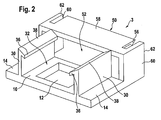
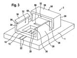
- Glasscheibe (1), die umfaßt: mindestens einen daran befestigten Stützsockel (3), wobei der Stützsockel (3) dem abnehmbaren Befestigen eines Einbauteils (2) der Glasscheibe (1) dient und umfaßt:(a) ein Basisteil (10),(b) mindestens einen ersten Anordnungsraum (32) zum Anordnen eines Halteabschnitts (4) eines Einbauteils (2), das in der Bewegungsrichtung senkrecht zum Basisteil (10) einführbar ist, und gekennzeichnet ist durch(c) mindestens einen zweiten Anordnungsraum (52) zum Anordnen eines Halteabschnitts (4) eines weiteren Einbauteils (2), das in der Bewegungsrichtung parallel zum Basisteil (10) einführbar ist.
- Glasscheibe (1) nach Anspruch 1, wobei das Basisteil (10) zur Befestigung, insbesondere zum Kleben, des Stützsockels (3) an die Glasscheibe (1) vorgesehen ist.
- Glasscheibe (1) nach Anspruch 2, wobei der Stützsockel (3) mindestens zwei Seitenwände (30) umfaßt, die an der Seite des Basisteils (10) angeordnet sind, die von der Glasscheibe (1) abgewandt ist und die senkrecht zum Basisteil (10) verlaufen, wobei die Seitenwände den ersten Anordnungsraum (32) zwischen sich einschließen.
- Glasscheibe (1) nach Anspruch 2, dadurch gekennzeichnet, dass mindestens ein Befestigungselement (36) im Bereich der Seitenwände (30)vorgesehen ist, mit dem ein Halteabschnitt (4) des Einbauteils (2) im ersten Anordnungsraum (32) befestigt werden kann.
- Glasscheibe (1) nach Anspruch 4, dadurch gekennzeichnet, dass das Befestigungselement (36) mindestens eine Einrast-Leiste umfaßt, die parallel zum Basisteil (10) verläuft.
- Glasscheibe (1) nach einem der Ansprüche 3 bis 5, dadurch gekennzeichnet, dass die oberen Kanten (38) der Seitenwände (30), die vom Basisteil (10) abgewandt sind, zumindest in Zonen trichterförmig abgeschrägt sind.
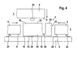
- Glasscheibe (1) nach einem der Ansprüche 3 bis 6, dadurch gekennzeichnet, dass das Basisteil (10) mindestens ein Durchgangsloch (12) aufweist, das zwischen den Seitenwänden (30), angeordnet ist, wobei das Durchgangsloch einen direkten Kontakt des im Stützsockel (3) mit der Glasscheibe (1) befestigten Einbauteils (2) ermöglicht.
- Glasscheibe (1) nach Anspruch 7, dadurch gekennzeichnet, dass das Durchgangsloch (12) rundherum vom Basisteil (10) eingefaßt ist.
- Glasscheibe (1) nach einem der Ansprüche 3 bis 8, dadurch gekennzeichnet, dass das Basisteil (10) einen an den Seitenwänden (30) anliegenden Klebeflansch (14) aufweist.
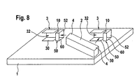
- Glasscheibe (1) nach einem der Ansprüche 3 bis 9, wobei der Stützsockel (3) mindestens eine Brücke (50) enthält, die zusammen mit dem Basisteil (10) oder der Glasscheibe (1) einen tunnelförmigen zweiten Anordnungsraum (52) bildet.
- Glasscheibe (1) nach Anspruch 10, dadurch gekennzeichnet, dass die Brücke (50) in Längsrichtung der Seitenwände (30) direkt auf die Seitenwände oder in einem Abstand zu diesen folgt.
- Glasscheibe (1) nach Anspruch 10 oder 11, dadurch gekennzeichnet, dass im Bereich der Brücke (50) mindestens ein Befestigungselement (56) vorgesehen ist, mit dem ein Halteabschnitt (4) des Einbauteils (2) im zweiten Anordnungsraum (32) befestigt werden kann.
- Glasscheibe (1) nach Anspruch 12, dadurch gekennzeichnet, dass das Befestigungselement (56) entlang eines Abdeckstabes (58) mindestens eine Einrast-Leiste und/oder eine Seitenstütze (60) der Brücke (50) umfaßt.
- Glasscheibe (1) nach einem der Ansprüche 10 bis 13, dadurch gekennzeichnet, dass die Außenkanten (62) der Brücke (50), die von den Seitenwänden (30) abgewandt sind, zumindest in Zonen trichterförmig abgeschrägt sind.
- Glasscheibe (1) nach einem der vorhergehenden Ansprüche, dadurch gekennzeichnet, dass mindestens eine Magnetführung oder ein Befestigungselement im Stützsockel (3) vorgesehen ist, wodurch die Einführung des Halteabschnitts (4) im zugehörigen Anordnungsraum (32, 52) erleichtert wird und/oder der Halteabschnitt (4) darin befestigt wird.
- Glasscheibe (1), die umfaßt: mindestens einen daran gemäß einem der Ansprüche 2 bis 15 befestigen Stützsockel (3) und ein Einbauteil (2), das abnehmbar an diesem (diesen) Stützsockel(n) (3) befestigt ist.
- Glasscheibe (1) nach Anspruch 16, wobei mindestens ein Stützsockel (3) ein Durchgangsloch(12) im Basisteil (10) aufweist, in dem sich mindestens ein Kontaktpunkt (20) einer elektrischen Anordnung auf der Glasscheibe (1) befindet, und wobei das Einbauteil (2) mindestens einen elektrischen Kontakt, insbesondere einen Federkontakt (24), aufweist, der diesem Kontaktpunkt (20) abnehmbar zugeordnet ist.
- Glasscheibe (1) nach Anspruch 1, wobei der Stützsockel (3) mindestens zwei Seitenwände (30) enthält, die senkrecht zum Basisteil (10) verlaufen, und die Seitenwände den ersten Anordnungsraum (32) zwischen sich einschließen.
- Glasscheibe (1) nach Anspruch 18, dadurch gekennzeichnet, dass mindestens ein Befestigungselement (36) im Bereich der Seitenwände (30) vorgesehen ist, mit dem ein Halteabschnitt (4) des Einbauteils (2) im ersten Anordnungsraum (32) befestigt werden kann.
- Glasscheibe (1) nach Anspruch 19, dadurch gekennzeichnet, dass das Befestigungselement (36) mindestens eine Einrast-Leiste umfaßt, die parallel zum Basisteil (10) verläuft.
- Glasscheibe (1) nach einem der Ansprüche 18 bis 20, dadurch gekennzeichnet, dass die oberen Kanten (38) der Seitenwände (30), die vom Basisteil (10) abgewandt sind, zumindest in Zonen trichterförmig abgeschrägt sind.
- Glasscheibe (1) nach einem der Ansprüche 18 bis 21, wobei der Stützsockel (3) mindestens eine Brücke (50) aufweist, die zusammen mit dem Basisteil (10) oder der Glasscheibe (1) einen tunnelförmigen zweiten Anordnungsraum (52) bildet.
- Glasscheibe (1) nach Anspruch 22, dadurch gekennzeichnet, dass die Brücke (50) in Längsrichtung der Seitenwände (30) denselben direkt oder mit einem Abstand folgt.
- Glasscheibe (1) nach Anspruch 22 oder 23, dadurch gekennzeichnet, dass im Bereich der Brücke (50) mindestens ein Befestigungselement (36) vorgesehen ist, mit dem ein Halteabschnitt (4) des Einbauteils (2) im zweiten Anordnungsraum (52) befestigt werden kann.
- Glasscheibe (1) nach Anspruch 24, dadurch gekennzeichnet, dass das Befestigungselement (56) mindestens eine Einrast-Leiste entlang des Abdeckstabes (58) und/oder eine Seitenstütze (60) der Brücke (50) aufweist.
- Glasscheibe (1) nach einem der Ansprüche 22 bis 25, dadurch gekennzeichnet, dass die Außenkanten (62) der Brücke (50), die von den Seitenwänden (30) abgewandt sind, zumindest in Zonen trichterförmig abgeschrägt sind.
- Glasscheibe (1) nach einem der Ansprüche 18 bis 26, dadurch gekennzeichnet, dass mindestens eine Magnetführung oder ein Befestigungselement im Stützsockel (3) vorgesehen ist, wodurch die Einführung des Halteabschnitts (4) in den zugehörigen Anordnungsraum (32, 52) erleichtert wird und/oder der Halteabschnitt (4) darin befestigt wird.
- Glasscheibe (1), die umfaßt: mindestens einen daran gemäß einem der Ansprüche 18 bis 27 befestigten Stützsockel (3) und ein Einbauteil (2), das an diesem (diesen) Stützsockel(n) (3) abnehmbar befestigt ist.
Priority Applications (1)
| Application Number | Priority Date | Filing Date | Title |
|---|---|---|---|
| PL06706356T PL1844520T3 (pl) | 2005-01-24 | 2006-01-23 | Szyba szklana z gniazdem zatrzymującym |
Applications Claiming Priority (2)
| Application Number | Priority Date | Filing Date | Title |
|---|---|---|---|
| DE102005003386A DE102005003386B3 (de) | 2005-01-24 | 2005-01-24 | Haltesockel zur lösbaren Befestigung eines Einbauteils an einer Glasscheibe |
| PCT/EP2006/000551 WO2006077149A1 (en) | 2005-01-24 | 2006-01-23 | Retaining socket |
Publications (2)
| Publication Number | Publication Date |
|---|---|
| EP1844520A1 EP1844520A1 (de) | 2007-10-17 |
| EP1844520B1 true EP1844520B1 (de) | 2008-08-13 |
Family
ID=36118191
Family Applications (1)
| Application Number | Title | Priority Date | Filing Date |
|---|---|---|---|
| EP06706356A Active EP1844520B1 (de) | 2005-01-24 | 2006-01-23 | Glasscheibe mit einem stützsockel |
Country Status (10)
| Country | Link |
|---|---|
| US (1) | US7780454B2 (de) |
| EP (1) | EP1844520B1 (de) |
| JP (1) | JP4700070B2 (de) |
| CN (1) | CN101120481B (de) |
| AT (1) | ATE405000T1 (de) |
| BR (1) | BRPI0606503B1 (de) |
| DE (2) | DE102005003386B3 (de) |
| ES (1) | ES2311276T3 (de) |
| PL (1) | PL1844520T3 (de) |
| WO (1) | WO2006077149A1 (de) |
Families Citing this family (26)
| Publication number | Priority date | Publication date | Assignee | Title |
|---|---|---|---|---|
| US6124886A (en) | 1997-08-25 | 2000-09-26 | Donnelly Corporation | Modular rearview mirror assembly |
| US6326613B1 (en) | 1998-01-07 | 2001-12-04 | Donnelly Corporation | Vehicle interior mirror assembly adapted for containing a rain sensor |
| US6278377B1 (en) | 1999-08-25 | 2001-08-21 | Donnelly Corporation | Indicator for vehicle accessory |
| US6445287B1 (en) | 2000-02-28 | 2002-09-03 | Donnelly Corporation | Tire inflation assistance monitoring system |
| US8288711B2 (en) | 1998-01-07 | 2012-10-16 | Donnelly Corporation | Interior rearview mirror system with forwardly-viewing camera and a control |
| US6420975B1 (en) | 1999-08-25 | 2002-07-16 | Donnelly Corporation | Interior rearview mirror sound processing system |
| US7480149B2 (en) | 2004-08-18 | 2009-01-20 | Donnelly Corporation | Accessory module for vehicle |
| WO2001064481A2 (en) | 2000-03-02 | 2001-09-07 | Donnelly Corporation | Video mirror systems incorporating an accessory module |
| US6396408B2 (en) | 2000-03-31 | 2002-05-28 | Donnelly Corporation | Digital electrochromic circuit with a vehicle network |
| WO2003065084A1 (en) | 2002-01-31 | 2003-08-07 | Donnelly Corporation | Vehicle accessory module |
| WO2006063827A1 (en) | 2004-12-15 | 2006-06-22 | Magna Donnelly Electronics Naas Limited | An accessory module system for a vehicle window |
| GB0624201D0 (en) * | 2006-12-04 | 2007-01-10 | Pilkington Automotive D Gmbh | Connector |
| GB0702938D0 (en) | 2007-02-15 | 2007-03-28 | Pilkington Automotive D Gmbh | Retaining socket for automotive glazing |
| DE102007014534A1 (de) * | 2007-03-27 | 2008-10-02 | Leopold Kostal Gmbh & Co. Kg | Dachintegrationsmodul |
| DE102007026460B4 (de) * | 2007-06-05 | 2023-02-23 | Volkswagen Ag | Befestigungsanordnung für eine Elektronikkomponente in einem Fahrzeug |
| DE102008011806B3 (de) | 2008-02-29 | 2009-09-24 | Yamaichi Electronics Deutschland Gmbh | Verbindersystem, Verwendung, Verfahren, Verbinderhalteeinrichtung und Verbinder |
| DE102008044840A1 (de) * | 2008-08-28 | 2010-03-04 | Leopold Kostal Gmbh & Co. Kg | Sensoranordnung für ein Kraftfahrzeug |
| DE102008044839A1 (de) | 2008-08-28 | 2010-03-04 | Leopold Kostal Gmbh & Co. Kg | Sensoranordnung für ein Kraftfahrzeug |
| US8570374B2 (en) | 2008-11-13 | 2013-10-29 | Magna Electronics Inc. | Camera for vehicle |
| JP5972716B2 (ja) * | 2012-09-03 | 2016-08-17 | 小島プレス工業株式会社 | 車両ウィンドウ用アンプ装置 |
| US20220189864A1 (en) * | 2014-05-24 | 2022-06-16 | Broadpak Corporation | 3d integrations and methods of making thereof |
| DE102016006775A1 (de) * | 2016-06-02 | 2017-12-07 | Rosenberger Hochfrequenztechnik Gmbh & Co. Kg | Elektrische Steckverbindung |
| CN107984983A (zh) * | 2017-11-24 | 2018-05-04 | 广东菲柯特电子科技有限公司 | 一种悬挂式胎压仪 |
| FR3086410B1 (fr) * | 2018-09-24 | 2020-12-11 | Alstom Transp Tech | Interface usb destinee a equiper un vehicule de transport public |
| KR20220106130A (ko) * | 2019-12-03 | 2022-07-28 | 에이지씨 가부시키가이샤 | 스페이서를 구비한 안테나 유닛 및 안테나 유닛을 구비한 유리창 |
| WO2023144546A1 (en) | 2022-01-26 | 2023-08-03 | Pilkington Group Limited | Sensor bracket glazing |
Family Cites Families (17)
| Publication number | Priority date | Publication date | Assignee | Title |
|---|---|---|---|---|
| FR2132920A5 (de) | 1971-04-01 | 1972-11-24 | Cipa | |
| FR2210958A6 (de) | 1972-12-19 | 1974-07-12 | Cipa | |
| JPS5637338Y2 (de) * | 1977-11-09 | 1981-09-01 | ||
| JPH032709U (de) * | 1989-05-29 | 1991-01-11 | ||
| US5035635A (en) * | 1990-09-04 | 1991-07-30 | Tsai Shiang Shiun | Revolving safety socket |
| JPH082926Y2 (ja) * | 1991-03-29 | 1996-01-29 | 日本板硝子株式会社 | アンテナコネクタ |
| JPH0575981U (ja) * | 1992-03-18 | 1993-10-15 | 矢崎総業株式会社 | ガラス板用コネクタ |
| FR2717011B1 (fr) * | 1994-03-02 | 1996-03-29 | Telemecanique | Conecteur pour canalisation électrique. |
| FR2739333B1 (fr) * | 1995-09-29 | 1997-11-14 | Valeo Systemes Dessuyage | Essuie-glace muni d'un deflecteur souple fixe sur des griffes de fixation de la raclette d'essuyage |
| DE19633933A1 (de) | 1996-08-22 | 1998-04-02 | Gore W L & Ass Gmbh | Bandkabel-Verbinder |
| US6234820B1 (en) * | 1997-07-21 | 2001-05-22 | Rambus Inc. | Method and apparatus for joining printed circuit boards |
| US5898183A (en) * | 1997-10-16 | 1999-04-27 | Libbey-Owens-Ford Co. | Compact moisture sensor with efficient high obliquity optics |
| DE19823202C2 (de) | 1998-05-25 | 2003-05-28 | Hirschmann Electronics Gmbh | Fahrzeug-Antenneneinrichtung |
| US6704204B1 (en) * | 1998-06-23 | 2004-03-09 | Intel Corporation | IC package with edge connect contacts |
| US6083038A (en) * | 1998-08-05 | 2000-07-04 | Osram Sylvania Inc. | Bracket assembly |
| DE10211444B4 (de) * | 2002-03-15 | 2004-11-18 | Daimlerchrysler Ag | Halterung zum Befestigen eines Bauteils an einer Glasscheibe |
| DE20215634U1 (de) * | 2002-10-11 | 2004-02-19 | Pilkington Automotive Deutschland Gmbh | Fahrzeugglasscheibe |
-
2005
- 2005-01-24 DE DE102005003386A patent/DE102005003386B3/de active Active
-
2006
- 2006-01-23 DE DE602006002250T patent/DE602006002250D1/de active Active
- 2006-01-23 WO PCT/EP2006/000551 patent/WO2006077149A1/en active IP Right Grant
- 2006-01-23 PL PL06706356T patent/PL1844520T3/pl unknown
- 2006-01-23 ES ES06706356T patent/ES2311276T3/es active Active
- 2006-01-23 CN CN2006800052353A patent/CN101120481B/zh active Active
- 2006-01-23 US US11/795,817 patent/US7780454B2/en active Active
- 2006-01-23 EP EP06706356A patent/EP1844520B1/de active Active
- 2006-01-23 BR BRPI0606503-1A patent/BRPI0606503B1/pt active IP Right Grant
- 2006-01-23 AT AT06706356T patent/ATE405000T1/de not_active IP Right Cessation
- 2006-01-23 JP JP2007551627A patent/JP4700070B2/ja active Active
Also Published As
| Publication number | Publication date |
|---|---|
| US20080272260A1 (en) | 2008-11-06 |
| CN101120481A (zh) | 2008-02-06 |
| WO2006077149A1 (en) | 2006-07-27 |
| US7780454B2 (en) | 2010-08-24 |
| ATE405000T1 (de) | 2008-08-15 |
| CN101120481B (zh) | 2011-11-16 |
| JP4700070B2 (ja) | 2011-06-15 |
| BRPI0606503A2 (pt) | 2009-06-30 |
| DE102005003386B3 (de) | 2006-06-08 |
| PL1844520T3 (pl) | 2009-01-30 |
| ES2311276T3 (es) | 2009-02-01 |
| JP2008529206A (ja) | 2008-07-31 |
| EP1844520A1 (de) | 2007-10-17 |
| BRPI0606503B1 (pt) | 2019-02-19 |
| DE602006002250D1 (de) | 2008-09-25 |
Similar Documents
| Publication | Publication Date | Title |
|---|---|---|
| EP1844520B1 (de) | Glasscheibe mit einem stützsockel | |
| US6411259B1 (en) | Automobile antenna device | |
| CN101373887B (zh) | 用于机动车辆的电接线盒 | |
| US20110109115A1 (en) | Terminal structure and glass plate with terminal for vehicles | |
| US7592960B2 (en) | High frequency capacitive coupling antenna for vehicles | |
| CN106879162B (zh) | 柔性印刷电路板以及包括该印刷电路板的用于机动车辆的灯模块 | |
| US20100277018A1 (en) | Device for the contact and attachment of an electric component in a motor vehicle | |
| KR20070027456A (ko) | 급전의 신뢰성이 높은 차량 탑재용 안테나장치 | |
| US8535095B2 (en) | Clip-type elastic contact piece and shielded connector housing assembly having the same | |
| JP2018037664A (ja) | 電気部品とプリント回路基板とを電気的に接続するためのフレキシブルデバイス、システム、及びシステム取り付け方法 | |
| US20080291650A1 (en) | Arrangement Having an Electric Motor and a Main Printed Circuit Board, and an Assembly Method | |
| US20060238428A1 (en) | Domed circuit board of an antenna amplifier for a vehicle antenna device | |
| US20090206219A1 (en) | Carrier for Holding an Antenna Amplifier of a Vehicle | |
| KR100391665B1 (ko) | 자동차 윈도우의 열선 컨넥터 구조 | |
| MXPA06006861A (es) | Dispositivo para sujetar un modulo conectador en un soporte de modulo. | |
| US20100039780A1 (en) | Electronic Device for a Vehicle Having a Printed Circuit B | |
| KR101956750B1 (ko) | 전자 제어 장치 | |
| JP7284832B2 (ja) | 車両用センサユニット | |
| JP2011097187A (ja) | ガラスアンテナ用電子部品 | |
| JP3098997U (ja) | アンテナ用アンプ | |
| JP5191346B2 (ja) | 車載用アンテナ | |
| CN109643838B (zh) | 天线电子盒在车辆的尾盖上的安装 | |
| US20100255692A1 (en) | Electrical connection system | |
| US7161546B2 (en) | Clip like contact element | |
| JP2012216945A (ja) | 車載用アンテナ装置 |
Legal Events
| Date | Code | Title | Description |
|---|---|---|---|
| PUAI | Public reference made under article 153(3) epc to a published international application that has entered the european phase |
Free format text: ORIGINAL CODE: 0009012 |
|
| 17P | Request for examination filed |
Effective date: 20070824 |
|
| AK | Designated contracting states |
Kind code of ref document: A1 Designated state(s): AT BE BG CH CY CZ DE DK EE ES FI FR GB GR HU IE IS IT LI LT LU LV MC NL PL PT RO SE SI SK TR |
|
| DAX | Request for extension of the european patent (deleted) | ||
| RTI1 | Title (correction) |
Free format text: GLASS PANE WITH A RETAINING SOCKET |
|
| GRAP | Despatch of communication of intention to grant a patent |
Free format text: ORIGINAL CODE: EPIDOSNIGR1 |
|
| GRAS | Grant fee paid |
Free format text: ORIGINAL CODE: EPIDOSNIGR3 |
|
| GRAA | (expected) grant |
Free format text: ORIGINAL CODE: 0009210 |
|
| AK | Designated contracting states |
Kind code of ref document: B1 Designated state(s): AT BE BG CH CY CZ DE DK EE ES FI FR GB GR HU IE IS IT LI LT LU LV MC NL PL PT RO SE SI SK TR |
|
| REG | Reference to a national code |
Ref country code: GB Ref legal event code: FG4D |
|
| REG | Reference to a national code |
Ref country code: CH Ref legal event code: EP |
|
| REG | Reference to a national code |
Ref country code: IE Ref legal event code: FG4D |
|
| REF | Corresponds to: |
Ref document number: 602006002250 Country of ref document: DE Date of ref document: 20080925 Kind code of ref document: P |
|
| PG25 | Lapsed in a contracting state [announced via postgrant information from national office to epo] |
Ref country code: NL Free format text: LAPSE BECAUSE OF FAILURE TO SUBMIT A TRANSLATION OF THE DESCRIPTION OR TO PAY THE FEE WITHIN THE PRESCRIBED TIME-LIMIT Effective date: 20080813 Ref country code: LT Free format text: LAPSE BECAUSE OF FAILURE TO SUBMIT A TRANSLATION OF THE DESCRIPTION OR TO PAY THE FEE WITHIN THE PRESCRIBED TIME-LIMIT Effective date: 20080813 Ref country code: IS Free format text: LAPSE BECAUSE OF FAILURE TO SUBMIT A TRANSLATION OF THE DESCRIPTION OR TO PAY THE FEE WITHIN THE PRESCRIBED TIME-LIMIT Effective date: 20081213 |
|
| REG | Reference to a national code |
Ref country code: PL Ref legal event code: T3 |
|
| REG | Reference to a national code |
Ref country code: ES Ref legal event code: FG2A Ref document number: 2311276 Country of ref document: ES Kind code of ref document: T3 |
|
| PG25 | Lapsed in a contracting state [announced via postgrant information from national office to epo] |
Ref country code: FI Free format text: LAPSE BECAUSE OF FAILURE TO SUBMIT A TRANSLATION OF THE DESCRIPTION OR TO PAY THE FEE WITHIN THE PRESCRIBED TIME-LIMIT Effective date: 20080813 Ref country code: AT Free format text: LAPSE BECAUSE OF FAILURE TO SUBMIT A TRANSLATION OF THE DESCRIPTION OR TO PAY THE FEE WITHIN THE PRESCRIBED TIME-LIMIT Effective date: 20080813 Ref country code: SI Free format text: LAPSE BECAUSE OF FAILURE TO SUBMIT A TRANSLATION OF THE DESCRIPTION OR TO PAY THE FEE WITHIN THE PRESCRIBED TIME-LIMIT Effective date: 20080813 Ref country code: LV Free format text: LAPSE BECAUSE OF FAILURE TO SUBMIT A TRANSLATION OF THE DESCRIPTION OR TO PAY THE FEE WITHIN THE PRESCRIBED TIME-LIMIT Effective date: 20080813 |
|
| PG25 | Lapsed in a contracting state [announced via postgrant information from national office to epo] |
Ref country code: BE Free format text: LAPSE BECAUSE OF FAILURE TO SUBMIT A TRANSLATION OF THE DESCRIPTION OR TO PAY THE FEE WITHIN THE PRESCRIBED TIME-LIMIT Effective date: 20080813 |
|
| PG25 | Lapsed in a contracting state [announced via postgrant information from national office to epo] |
Ref country code: DK Free format text: LAPSE BECAUSE OF FAILURE TO SUBMIT A TRANSLATION OF THE DESCRIPTION OR TO PAY THE FEE WITHIN THE PRESCRIBED TIME-LIMIT Effective date: 20080813 Ref country code: BG Free format text: LAPSE BECAUSE OF FAILURE TO SUBMIT A TRANSLATION OF THE DESCRIPTION OR TO PAY THE FEE WITHIN THE PRESCRIBED TIME-LIMIT Effective date: 20081113 |
|
| PG25 | Lapsed in a contracting state [announced via postgrant information from national office to epo] |
Ref country code: PT Free format text: LAPSE BECAUSE OF FAILURE TO SUBMIT A TRANSLATION OF THE DESCRIPTION OR TO PAY THE FEE WITHIN THE PRESCRIBED TIME-LIMIT Effective date: 20090113 Ref country code: SK Free format text: LAPSE BECAUSE OF FAILURE TO SUBMIT A TRANSLATION OF THE DESCRIPTION OR TO PAY THE FEE WITHIN THE PRESCRIBED TIME-LIMIT Effective date: 20080813 Ref country code: RO Free format text: LAPSE BECAUSE OF FAILURE TO SUBMIT A TRANSLATION OF THE DESCRIPTION OR TO PAY THE FEE WITHIN THE PRESCRIBED TIME-LIMIT Effective date: 20080813 |
|
| PLBE | No opposition filed within time limit |
Free format text: ORIGINAL CODE: 0009261 |
|
| STAA | Information on the status of an ep patent application or granted ep patent |
Free format text: STATUS: NO OPPOSITION FILED WITHIN TIME LIMIT |
|
| 26N | No opposition filed |
Effective date: 20090514 |
|
| PG25 | Lapsed in a contracting state [announced via postgrant information from national office to epo] |
Ref country code: EE Free format text: LAPSE BECAUSE OF FAILURE TO SUBMIT A TRANSLATION OF THE DESCRIPTION OR TO PAY THE FEE WITHIN THE PRESCRIBED TIME-LIMIT Effective date: 20080813 |
|
| PG25 | Lapsed in a contracting state [announced via postgrant information from national office to epo] |
Ref country code: MC Free format text: LAPSE BECAUSE OF NON-PAYMENT OF DUE FEES Effective date: 20090131 |
|
| PG25 | Lapsed in a contracting state [announced via postgrant information from national office to epo] |
Ref country code: IE Free format text: LAPSE BECAUSE OF NON-PAYMENT OF DUE FEES Effective date: 20090123 Ref country code: SE Free format text: LAPSE BECAUSE OF FAILURE TO SUBMIT A TRANSLATION OF THE DESCRIPTION OR TO PAY THE FEE WITHIN THE PRESCRIBED TIME-LIMIT Effective date: 20081113 |
|
| REG | Reference to a national code |
Ref country code: CH Ref legal event code: PL |
|
| PG25 | Lapsed in a contracting state [announced via postgrant information from national office to epo] |
Ref country code: LI Free format text: LAPSE BECAUSE OF NON-PAYMENT OF DUE FEES Effective date: 20100131 Ref country code: GR Free format text: LAPSE BECAUSE OF FAILURE TO SUBMIT A TRANSLATION OF THE DESCRIPTION OR TO PAY THE FEE WITHIN THE PRESCRIBED TIME-LIMIT Effective date: 20081114 Ref country code: CH Free format text: LAPSE BECAUSE OF NON-PAYMENT OF DUE FEES Effective date: 20100131 |
|
| PG25 | Lapsed in a contracting state [announced via postgrant information from national office to epo] |
Ref country code: LU Free format text: LAPSE BECAUSE OF NON-PAYMENT OF DUE FEES Effective date: 20090123 |
|
| PG25 | Lapsed in a contracting state [announced via postgrant information from national office to epo] |
Ref country code: HU Free format text: LAPSE BECAUSE OF FAILURE TO SUBMIT A TRANSLATION OF THE DESCRIPTION OR TO PAY THE FEE WITHIN THE PRESCRIBED TIME-LIMIT Effective date: 20090214 |
|
| PG25 | Lapsed in a contracting state [announced via postgrant information from national office to epo] |
Ref country code: TR Free format text: LAPSE BECAUSE OF FAILURE TO SUBMIT A TRANSLATION OF THE DESCRIPTION OR TO PAY THE FEE WITHIN THE PRESCRIBED TIME-LIMIT Effective date: 20080813 |
|
| PG25 | Lapsed in a contracting state [announced via postgrant information from national office to epo] |
Ref country code: CY Free format text: LAPSE BECAUSE OF FAILURE TO SUBMIT A TRANSLATION OF THE DESCRIPTION OR TO PAY THE FEE WITHIN THE PRESCRIBED TIME-LIMIT Effective date: 20080813 |
|
| REG | Reference to a national code |
Ref country code: FR Ref legal event code: PLFP Year of fee payment: 11 |
|
| REG | Reference to a national code |
Ref country code: FR Ref legal event code: PLFP Year of fee payment: 12 |
|
| REG | Reference to a national code |
Ref country code: FR Ref legal event code: PLFP Year of fee payment: 13 |
|
| PGFP | Annual fee paid to national office [announced via postgrant information from national office to epo] |
Ref country code: FR Payment date: 20230123 Year of fee payment: 18 Ref country code: ES Payment date: 20230216 Year of fee payment: 18 Ref country code: CZ Payment date: 20230112 Year of fee payment: 18 |
|
| PGFP | Annual fee paid to national office [announced via postgrant information from national office to epo] |
Ref country code: PL Payment date: 20230116 Year of fee payment: 18 Ref country code: IT Payment date: 20230131 Year of fee payment: 18 |
|
| P01 | Opt-out of the competence of the unified patent court (upc) registered |
Effective date: 20230514 |
|
| PGFP | Annual fee paid to national office [announced via postgrant information from national office to epo] |
Ref country code: ES Payment date: 20240216 Year of fee payment: 19 |
|
| PGFP | Annual fee paid to national office [announced via postgrant information from national office to epo] |
Ref country code: DE Payment date: 20240119 Year of fee payment: 19 Ref country code: CZ Payment date: 20240111 Year of fee payment: 19 Ref country code: GB Payment date: 20240117 Year of fee payment: 19 |