EP1844520B1 - Glass pane with a retaining socket - Google Patents
Glass pane with a retaining socket Download PDFInfo
- Publication number
- EP1844520B1 EP1844520B1 EP06706356A EP06706356A EP1844520B1 EP 1844520 B1 EP1844520 B1 EP 1844520B1 EP 06706356 A EP06706356 A EP 06706356A EP 06706356 A EP06706356 A EP 06706356A EP 1844520 B1 EP1844520 B1 EP 1844520B1
- Authority
- EP
- European Patent Office
- Prior art keywords
- glass pane
- retaining
- base part
- built
- accommodation space
- Prior art date
- Legal status (The legal status is an assumption and is not a legal conclusion. Google has not performed a legal analysis and makes no representation as to the accuracy of the status listed.)
- Active
Links
- 239000011521 glass Substances 0.000 title claims abstract description 130
- 230000004308 accommodation Effects 0.000 claims description 84
- 230000005291 magnetic effect Effects 0.000 claims description 6
- 238000004026 adhesive bonding Methods 0.000 claims description 3
- 239000000853 adhesive Substances 0.000 abstract description 17
- 230000001070 adhesive effect Effects 0.000 abstract description 17
- 238000009434 installation Methods 0.000 abstract description 4
- 230000014759 maintenance of location Effects 0.000 description 10
- 238000005476 soldering Methods 0.000 description 7
- 239000000463 material Substances 0.000 description 5
- 229920003023 plastic Polymers 0.000 description 5
- 238000003466 welding Methods 0.000 description 5
- 239000004033 plastic Substances 0.000 description 4
- 238000000034 method Methods 0.000 description 3
- 229920001707 polybutylene terephthalate Polymers 0.000 description 3
- 229910000679 solder Inorganic materials 0.000 description 3
- 238000006073 displacement reaction Methods 0.000 description 2
- 238000005516 engineering process Methods 0.000 description 2
- 239000003365 glass fiber Substances 0.000 description 2
- 238000004519 manufacturing process Methods 0.000 description 2
- 229910052751 metal Inorganic materials 0.000 description 2
- 239000002184 metal Substances 0.000 description 2
- 150000002739 metals Chemical class 0.000 description 2
- 230000008439 repair process Effects 0.000 description 2
- FYYHWMGAXLPEAU-UHFFFAOYSA-N Magnesium Chemical compound [Mg] FYYHWMGAXLPEAU-UHFFFAOYSA-N 0.000 description 1
- BQCADISMDOOEFD-UHFFFAOYSA-N Silver Chemical compound [Ag] BQCADISMDOOEFD-UHFFFAOYSA-N 0.000 description 1
- 229910045601 alloy Inorganic materials 0.000 description 1
- 239000000956 alloy Substances 0.000 description 1
- 230000005540 biological transmission Effects 0.000 description 1
- 239000000969 carrier Substances 0.000 description 1
- 238000005266 casting Methods 0.000 description 1
- 239000004020 conductor Substances 0.000 description 1
- 238000001514 detection method Methods 0.000 description 1
- 238000011161 development Methods 0.000 description 1
- 230000018109 developmental process Effects 0.000 description 1
- 230000000694 effects Effects 0.000 description 1
- 230000005294 ferromagnetic effect Effects 0.000 description 1
- 239000003292 glue Substances 0.000 description 1
- 238000010438 heat treatment Methods 0.000 description 1
- 238000001746 injection moulding Methods 0.000 description 1
- 238000003780 insertion Methods 0.000 description 1
- 230000037431 insertion Effects 0.000 description 1
- 239000005340 laminated glass Substances 0.000 description 1
- 229910052749 magnesium Inorganic materials 0.000 description 1
- 239000011777 magnesium Substances 0.000 description 1
- 230000003287 optical effect Effects 0.000 description 1
- 239000002245 particle Substances 0.000 description 1
- -1 polybutylene terephthalate Polymers 0.000 description 1
- 229920001296 polysiloxane Polymers 0.000 description 1
- 229910052709 silver Inorganic materials 0.000 description 1
- 239000004332 silver Substances 0.000 description 1
- 239000000243 solution Substances 0.000 description 1
- 239000000758 substrate Substances 0.000 description 1
Images


Classifications
-
- H—ELECTRICITY
- H01—ELECTRIC ELEMENTS
- H01Q—ANTENNAS, i.e. RADIO AERIALS
- H01Q1/00—Details of, or arrangements associated with, antennas
- H01Q1/12—Supports; Mounting means
- H01Q1/1271—Supports; Mounting means for mounting on windscreens
-
- H—ELECTRICITY
- H01—ELECTRIC ELEMENTS
- H01R—ELECTRICALLY-CONDUCTIVE CONNECTIONS; STRUCTURAL ASSOCIATIONS OF A PLURALITY OF MUTUALLY-INSULATED ELECTRICAL CONNECTING ELEMENTS; COUPLING DEVICES; CURRENT COLLECTORS
- H01R13/00—Details of coupling devices of the kinds covered by groups H01R12/70 or H01R24/00 - H01R33/00
- H01R13/73—Means for mounting coupling parts to apparatus or structures, e.g. to a wall
-
- H—ELECTRICITY
- H01—ELECTRIC ELEMENTS
- H01R—ELECTRICALLY-CONDUCTIVE CONNECTIONS; STRUCTURAL ASSOCIATIONS OF A PLURALITY OF MUTUALLY-INSULATED ELECTRICAL CONNECTING ELEMENTS; COUPLING DEVICES; CURRENT COLLECTORS
- H01R2201/00—Connectors or connections adapted for particular applications
- H01R2201/02—Connectors or connections adapted for particular applications for antennas
-
- H—ELECTRICITY
- H01—ELECTRIC ELEMENTS
- H01R—ELECTRICALLY-CONDUCTIVE CONNECTIONS; STRUCTURAL ASSOCIATIONS OF A PLURALITY OF MUTUALLY-INSULATED ELECTRICAL CONNECTING ELEMENTS; COUPLING DEVICES; CURRENT COLLECTORS
- H01R2201/00—Connectors or connections adapted for particular applications
- H01R2201/26—Connectors or connections adapted for particular applications for vehicles
Landscapes
- Securing Of Glass Panes Or The Like (AREA)
- Connection Of Plates (AREA)
- Clamps And Clips (AREA)
- Connecting Device With Holders (AREA)
- Load-Bearing And Curtain Walls (AREA)
- Supports Or Holders For Household Use (AREA)
- Window Of Vehicle (AREA)
- Details Of Aerials (AREA)
Abstract
Description
- The invention relates to glass panes, in particular automotive glass panes, with built-in components detachably fixed thereto with the aid of retaining sockets, and to retaining sockets for the same.
- Glass panes and in particular automotive glass panes are being equipped with an ever-increasing diversity of functions, which as a rule are made available by means of built-in parts connected permanently or detachably to the glass pane. Several examples of such functions are the reception and transmission of electromagnetic signals with the aid of antennas for frequency ranges in the kHz range up to the GHz range, the detection of ambient conditions or of signals with the aid of sensors such as rain, temperature or light sensors, the emission of light with the aid of brake or signal lights, the use of glass panes as carriers of devices such as mirrors using mirror bosses, and many more. The built-in parts to be affixed in this regard to the glass panes comprise elements such as, for example, antennas, electronic components such as for example antenna amplifiers, terminals or connectors, brake lights in the form of individual lights or light clusters, optical or electrical rain sensors and many others.
- In some cases, the built-in parts are not only to be mechanically connected to the glass pane, but in addition an electrical connection is to be produced with contacting points of functional elements such as antennas, heating elements or suchlike integrated into the glass pane or connected thereto, said contacting points being disposed on or in the glass pane.
- The mechanical connection of built-in parts to glass panes takes place in practice, for example, by means of techniques such as gluing, clamping, moulding-on, soldering, welding. Drawbacks of such connecting techniques, which as a rule are permanent and undetachable, are, amongst others, the costly production of the mechanical connection, which on account of the application-specific character frequently cannot be automated or can be so only with large investment outlay, as well as a high outlay in the event of any repairs.
- For the electrical connection of built-in parts with contacting points on/in the glass pane, use is usually made of soldering techniques, but also electrically conductive adhesives. It has also been proposed to press electrical contacts of built-in parts using elastic prestressing against assigned contacting points on the glass pane and thus to provide an electrical contact (amongst others,
WO 2004/034510 A1 ). - It is common, especially for the detachable fixing of built-in parts such as interior mirrors or rain sensors on windscreens of motor vehicles, firstly to glue a retaining socket to the glass pane and then, at the latest after the installation of the glass pane in the motor vehicle, to connect the built-in part mechanically to the retaining socket and thereby to fix it to the glass pane (e.g.
WO 99/21206 Al - The use of a retaining socket has also already been proposed for the fixing of high-frequency devices, i.e. antenna amplifiers or antenna matching circuits.
DE 198 23 202 C2 discloses a frame-like retaining socket for the detachable accommodation of one such high-frequency device. The frame-like retaining socket surrounds a plurality of contacting points of antenna conductors printed on the glass pane. It has, in the flat strip-like frame legs, projections pointing towards the frame interior, under which projections there can be pushed lugs provided at the edge of the high-frequency device to be accommodated by the retaining socket, as a result of which the high-frequency device is pressed against the glass pane in the accommodation space formed by the frame-like arrangement and is fixed thereto. The projections are designed either as guide rails disposed on three sides, which permit the high-frequency device to be pushed into the accommodation space parallel to the surface of the glass pane, or they are perforated. In the latter case, the high-frequency device is first introduced perpendicular to the glass pane into the accommodation space of the frame-like retaining socket and then pushed slightly to the side in the latter for the purpose of fixing. The high frequency device is equipped with spring contacts, which at the same time as the fixing of the high-frequency device make contact in a detachable manner with the contacting points on the glass pane inside the frame-like retaining socket. The previously known retaining socket is intended solely for the fixing of built-in parts such as antenna amplifiers to glass panes and is designed comparatively complex and costly, and on the other hand offers little flexibility of use. - Other technologies also consider the use of retaining sockets. For example,
US 6,704,204 discloses a casing for an IC card, where an IC package is inserted into a casing having two accommodation spaces.US 5,035,635 discloses a revolving safety socket, wherein the retaining socket into which a plug is inserted is able to rotate between electrical contacts.US 5,595,498 discloses a plug connector for electrical trunking, where the plug is inserted into a retaining socket having more than one accommodation space. However, none of these documents describe technologies suitable for fixing built-in parts to a glass pane. - The problem underlying the invention is to provide an improved retaining socket, which makes it possible to fix built-in parts of various kinds with various directions of movement during the fitting to glass panes. The retaining socket should be able to be produced cost-effectively and, if need be, enable an electrical contact between the built-in part and contacting points located on the glass pane for electrical arrangements or components integrated into the glass pane or connected therewith.
- The document
EP-A-0 506 451 discloses the features of the preamble ofindependent claim 1. - The solution to this problem is the subject-matter of
claim 1. Advantageous developments are given in sub-claims 2 - 28. - The retaining socket according to the invention is defined by
claim 1. - In an embodiment the base part is used for the fixing, in particular gluing, of the retaining socket to the glass pane. The description below mainly refers to this first embodiment. It is in many respects however also readable onto a more general aspect of the invention, wherein the base part primarily serves to provide a reference plane and support function common to both accommodation spaces and wherein the retaining socket may alternatively be attached to the glass pane via side walls and/or side supports such as described and explained herein later.
- The provision of the two different accommodation spaces makes it possible to use the same retaining socket for different fixing directions when fitting a built-in part. An individual retaining socket needs to have only comparatively small dimensions, since a number of retaining sockets can be disposed spaced apart from one another on the glass pane for the fixing of built-in parts with larger dimensions, whereby a retaining socket is assigned respectively to a retaining portion of the built-in part.
- The accommodation spaces are designed in such a way that a suitably shaped retaining portion can be accommodated therein and fixed detachably therein in the intended retention position. The fixing means assigned to an accommodation space can be disposed in the respective accommodation space or outside the latter. The accommodation spaces normally comprise guide elements such as rails or walls, so that the introduced retaining portion can be guided into the retention position according to the intended direction of movement and held therein.
- In order to achieve the aim of universal usability of the retaining socket according to invention, the first accommodation space is preferably constructed tank-shaped or channel-shaped, i.e. is open at the top viewed from the glass pane and thus permits the introduction of the corresponding retaining portion from above, i.e. essentially perpendicular to the glass pane. The second accommodation space, on the other hand, is preferably constructed tunnel-shaped or bridge-shaped, i.e. it has at all events a cover bar facing away from the glass pane, which prevents a retaining portion of the built-in part introduced into this accommodation space from moving away from the glass pane and thus mechanically secures the latter in the direction of movement perpendicular to the glass pane.
- More generally the first accommodation space permits the introduction of the corresponding retaining portion essentially perpendicular to the base part which may be arranged parallel or perpendicular to the glass pane whereas the second accommodation space is preferably constructed tunnel-shaped or bridge-shaped, i.e. it has at all events a cover bar facing away from the base part, which prevents a retaining portion of the built-in part introduced into this accommodation space from moving away perpendicular to the base part and thus mechanically secures the latter to the glass pane.
- The retaining socket preferably has at least two side walls disposed on the base part and - in its first embodiment - on its side facing away from the glass pane which run perpendicular to said base part (and optionally the glass pane), said side walls enclosing between them the first accommodation space. The side walls at least partially enclose between them the assigned retaining portion of the built-in part introduced into the first accommodation space. The retaining portion of the built-in part can be designed higher or lower than the side walls. It can in particular also continue beyond the first accommodation space, so that the side walls and in particular their upper edges are enclosed on both sides at least in zones by the retaining portion.
- As a rule, there is provided in the region of the side walls at least one fixing element, with which the retaining portion of the built-in part can be fixed in the first accommodation space after its introduction, i.e. secured against undesirable detachment or displacement especially opposite to the direction of movement during introduction after the retention position has been reached. The fixing element can preferably comprise at least one lock-in ridge running parallel to the base part. Lock-in ridge means an extended protrusion of at least one of the side walls, which either engages in an assigned recess of the retaining portion or grips over the retaining portion after the retention position has been reached. It goes without saying that, by means of suitable dimensioning and material selection of the side walls, it must be ensured, in case of need, that the latter can first be caused to give way by deformation when the retaining portion is introduced and finally return into a lock-in position fixing the retaining portion. Furthermore, it goes without saying that, in a reversal of the arrangement, a lock-in ridge can also be designed as a notch or groove in a side wall, into which an extended protrusion disposed in the retaining portion can engage.
- If such lock-in ridges are provided in the area of the side walls, this also facilitates pushing-in of a retaining portion of the built-in part parallel to the glass pane or more generally to the base part, into the first accommodation space as a further variant of the fixing of a built-in part with the aid of the retaining socket according to the invention. With this third fixing variant, the lock-in ridges act as guide rails for the retaining portion.
- The introduction of a retaining portion of the built-in part to be fixed into the first accommodation space is facilitated if the upper edges of the side walls facing away from the base part are bevelled in the manner of a funnel at least in zones, so that the retaining portion is centred or guided in the direction of the first accommodation space.
- The removal of the built-in part, e.g. for repair purposes, takes place by releasing the lock-in connection, for which purpose suitable tools can be used in a known manner. Alternatively, or additionally, the retaining socket can be equipped if need be with auxiliary means, with which the removal of the built-in part is facilitated.
- Especially when it is intended to produce, in the area of the retaining socket according to the invention, an electrical connection between the built-in part to be fixed and an electrical arrangement on the glass-pane side, it is preferable for, e.g., the base part to have at least one through-hole disposed between the side walls, which through-hole enables a direct contact of the built-in part fixed in the retaining socket or more precisely contacts disposed thereon, especially spring contacts, with the glass pane or contacting points located thereon. In the usual case, the through-hole extending at right angles to the base part or to the glass pane is surrounded all round by the base part, in particular for stability reasons. It lies within the scope of the invention, however, to leave open the base part, especially in the region of one of the end faces of the first accommodation space bounded by the side walls, and thus to form a through-hole open at least on one side in the plane of the base part. This can facilitate the pushing-in of a retaining portion of the built-in part, especially when electrical contacts are provided at its lower side.
- The base part serves, amongst other things, as a support for the elements of the retaining socket according to the invention that form the two accommodation spaces. Its lower side, if facing the glass pane in the installed state, is shaped flat or, if need be, curved according to the shape of the glass pane. The base part can be fixed to the glass pane with its underside in various ways, for example by soldering or friction welding, but especially by an adhesive joint. In the simplest form of embodiment, a part of or the whole of the underside of the base part serves as an adhesion surface, onto which a thin layer of a suitable adhesive is deposited prior to the fixing-on (pressing-on) of the retaining socket onto the glass pane. It is preferable for the base part to comprise separate adhesion flanges adjacent to the side walls, by means of which the retaining socket is glued to the glass pane. Instead of an adhesive joint, a soldered joint or the like can also be made in the region of the adhesion flange.
- Instead of an adhesive joint or soldering with adhesive or solder applied over the surface, it is also possible to work with adhesive deposits or solder deposits in adhesive chambers open to the bottom in the underside of the base part and in particular in the adhesion flanges.
- In an alternative arrangement the retaining socket may be affixed to the glass panes via other surfaces, e.g., via its side walls, which in this case need then to be configured such as described before in the context of the base part.
- According to a particularly preferred form of embodiment, the retaining socket according to the invention comprises at least one bridge, which together with the base part or (in the installed state of the first embodiment) with the glass pane forms the second, tunnel-like accommodation space, the bridge following on, especially in the longitudinal direction of the side walls, directly from the latter or with a spacing.
- As in the case of the first accommodation space, it is preferable for the second accommodation space if there is provided in the region of the bridge at least one fixing element, with which a retaining portion of the built-in part can be fixed in the second accommodation space, so that undesired detachment or displacement of the retaining portion of the built-in part introduced therein is prevented after the retention position has been reached.
- According to a preferred form of embodiment, the fixing element comprises at least one lock-in ridge along the cover bar and/or one of the side supports (as a rule disposed perpendicular to the base part or the glass pane) of the bridge.
- Corresponding to the first accommodation space, the outer edges of the bridge that face away from the side walls and from which the introduction of a retaining portion takes place into the second accommodation space, are preferably bevelled in a funnel-like manner at least in zones, so that the retaining portion is centred or guided in the direction of the second accommodation space.
- According to a further form of embodiment, the retaining socket comprises at least one magnetic guidance or fixing element, which can be disposed for example in the region of one of the accommodation spaces. There can be assigned to this magnetic guidance or fixing element at least one corresponding magnet or one ferromagnetic counterpart in the region of the retaining portion of the built-in part to be fixed thereto, so that the retaining portion is either guided by magnetic repulsion during the introduction into the respective accommodation space of the retaining socket or - in the case of opposite-pole magnets - is drawn into the retaining socket by magnetic attraction and is fixed in the retention position. This variant of the invention can facilitate and make more reliable the fixing of the built-in part at the intended place and in the desired orientation.
- The invention also relates to a glass pane, in particular an automotive glass pane, with at least one retaining socket according to the invention fixed to the latter. An individual retaining socket will as a rule suffice to fix smaller built-in parts to the glass pane, for example electrical plug-in connectors. For larger built-in parts such as brake lights, antennas, antenna amplifiers or the like, at least two of the retaining sockets according to the invention will as a rule be used, the universality of the retaining socket taking effect especially when one of the retaining portions is introduced parallel to the base part (to the glass pane) into the corresponding accommodation space of the assigned retaining socket and another is introduced perpendicular to the base part (to the glass pane) into the other accommodation space of a retaining socket of the same design. Especially when built-in parts having spring contacts are fixed in the retaining socket, it is recommendable to provide the spring contacts where a retaining portion is introduced into a tunnel-like second accommodation space. In this way, the elastic forces exerted by the spring contacts are absorbed most reliably and durably by the respective retaining socket.
- A particularly preferred application of the invention is an arrangement consisting of a glass pane and at least one retaining socket; wherein a retaining socket comprises a through-hole, e.g. in its base part, in which is disposed at least one contacting point of an electrical arrangement on the glass pane, the built-in part comprising at least one spring contact assigned to this contacting point.
- The retaining socket according to the invention can be produced from a large variety of materials. Not only from the cost standpoint is it particularly preferably made from plastic. It can be produced in particular as a one-piece component, in particular by injection moulding. The plastic should have a thermal expansion coefficient that does not differ too far from that of the glass pane, in order to avoid a thermally induced detachment of the retaining socket from the glass pane. At the time of the invention, glass-fibre reinforced polybutylene terephthalate (PBT) with a glass fibre proportion of up to approx. 50 vol.% (PBT GF 50) is regarded as a particularly suitable material. Instead of plastics, or combined with the latter, metals, such as for example magnesium or its alloys, or other materials can be used for the production of the retaining socket according to the invention, especially metals mouldable in the casting process.
- "Glass panes" comprise both single panes as well as multiple glazing units containing a number of individual panes, such as laminated glass panes or insulating glass panes, wherein the individual panes can be made from inorganic glass or also from transparent plastics. It goes without saying that the invention can also be employed when, instead of glass panes in the literal sense, sheet-like substrates of other materials are used.
- Insofar as terms such as "parallel" and "perpendicular" are used in the claims and the description for directions of movement or relative arrangements, they are also intended to comprise oblique or curved or combined directions of movement or relative arrangements, as long as the direction of movement or relative arrangement does not deviate overall by more than approx. 30° from the mathematically exact direction or relative arrangement.
- The invention will be explained in greater detail below with the aid of a graphic representation. The figures show the following:
- Fig. 1
- an automotive glass pane with two retaining sockets and a built-in part fixed thereto,
- Fig. 2
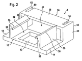
- a first embodiment of a retaining socket according to the invention in perspective view,
- Fig. 3
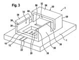
- a second embodiment of a retaining socket according to the invention in perspective view,
- Fig. 4
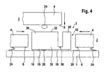
- a retaining socket on a glass pane in side view with three retaining portions of built-in parts introduceable in different directions of movement.
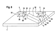
- Fig. 5 - 8
- four different arrangements of, in each case, two retaining sockets on a glass pane and built-in parts introduceable therein in different directions with their retaining portions.
- All the figures are diagrammatic views which are not to scale. Identical reference numbers designate identical parts.
- A
trapezoidal glass pane 1, i.e. an automotive glass pane such as for example a backlight or windscreen, is shown diagrammatically infigure 1 . Two retainingsockets 3 are fixed toglass pane 1 close to its upper pane edge, to which retaining sockets 3 a built-inpart 2 is fixed detachably with retainingportions 4. Built-inpart 2 could for example be a brake light, a rain sensor, an antenna or an antenna amplifier. In the region of left-hand retaining socket 3, there can be seen twosupply lines 22, which lead to this retainingsocket 3 and end in terminal faces (not shown in the general drawing offigure 1 ) beneath retainingsocket 3. Built-inpart 2 is supplied, for example, with energy via thesesupply lines 22 after the fixing in retainingsockets 3 or signals are routed from built-inpart 2 to a receiver on the vehicle side or from a transmitter on the vehicle side into built-inpart 2. - Two embodiments of retaining
socket 3 according to the invention are shown infigures 2 and3 . Retainingsocket 3 has a two-dimensionally extendingbase part 10, the underside whereof is intended for fixing to aglass pane 1 not shown here. Disposed onbase part 10 and perpendicular thereto are twoside walls 30 spaced apart from one another, which between them enclose afirst accommodation space 32 for accommodating a retaining portion 4 (not shown here) of a built-inpart 2.First accommodation space 32 is open to the top, so that retainingportion 4 can be introduced into it perpendicular tobase part 10 and parallel toside walls 30.Base part 10 has between side walls 30 a through-hole 12 extending perpendicular tobase part 10, via which through-hole 12 direct contact can be made between retainingportion 4 of built-inpart 2 andglass pane 1 or contactingpoints 20 located thereon. - In the region of through-
hole 12, there can be seen infigure 3 two contactingpoints 20 of an electrical arrangement located on the surface ofglass pane 1, to which contactingpoints supply lines 22 lead. - Upper edges 38 of
side walls 30 are bevelled in the manner of a funnel, which makes it easier to introduce into first accommodation space 32 a retainingportion 4 of built-inpart 2 to be fixed in retainingsocket 3. Upper edges 3 8 are at the same time designed as fixingelements 36 in the form of lock-in ridges, which ensure fixing of built-inpart 2 in the retention position. They could also serve as guide rails if, in another variant of the movement, a retainingportion 4 were pushed intofirst accommodation space 32 from the left parallel tobase part 10 instead of from above. - In the case of the first embodiment according to
figure 2 ,base part 10 comprises twoadhesion flanges 14 which, viewed fromfirst accommodation space 32, lie externally adjacent toside walls 30.Adhesion flanges 14 can be provided on their undersides with an adhesive, they can also comprise adhesive chambers open to the bottom, in which the adhesive is disposed with which retainingsocket 3 is glued toglass pane 1. In the two embodiments according tofigure 3 , the whole underside ofbase part 10 or a part thereof forms the adhesion surface. As an alternative to or in addition to an adhesive joint, another kind of mechanical, permanent connection toglass pane 1 could also take place, e.g. by soldering, welding or the like, where, for example, solder deposits or suchlike can be provided instead of an adhesive. - In the longitudinal direction of
side walls 30, there follows on from the lattersecond accommodation space 52, which lies beneath abridge 50, which comprises two side supports 60 and acover bar 58. In the case of the first embodiment according tofigure 2 ,base part 10 ends beforebridge 50, so that tunnel-likesecond accommodation space 52 is bounded all round bybridge 50 and - in the installed state -glass pane 1. In the second embodiment,base part 10 continues up to beneathbridge 50, so that in this casesecond accommodation space 52 is bounded all round bybridge 50 andbase part 10. - The inside width of
bridge 50 is greater than the distance betweenside walls 30 offirst accommodation space 32 in the first embodiment (figure 2 ) and is equal to the latter in the second embodiment (figure 3 ). It could also be smaller. Similarly, the height and the length of the twoaccommodation spaces second accommodation space 52 could also be designed as a through-hole in a transverse wall, which follows on fromside walls 30 directly or with a spacing, said through-hole extending parallel tobase part 10. - In the second form of embodiment according to
figure 3 ,cover bar 58 ofbridge 50 is designed as a continuous beam. At the same time, a fixingelement 56 is assigned jointly tofirst accommodation space 32 and tosecond accommodation space 52, said fixingelement 56 being formed as a recess (lock-in groove) inbase part 10. - In the case of the first embodiment according to
figure 2 ,cover bar 58 ofbridge 50 has a middle segment, which is separated by oblong notches from its end zones. The middle segment ofcover bar 58 is equipped with a fixingelement 56 in the form of a lock-in ridge. Due to the provision of the notches, it is able to become elastically deformed more easily than without the notches during the insertion of assigned retainingportion 4 and can move back after the retention position has been reached with the lock-in ridge locking into an assigned lock-in groove in retainingportion 4. - Side supports 60 and
cover bar 58 ofbridge 50 serve to guide and hold a retainingportion 4 of built-inpart 2 introduced parallel tobase part 10 andglass pane 1 intosecond accommodation space 52 and at the same time stiffen retainingsocket 3. Unlike the case of the two embodiments shown,outer edges 62 of the bridge could also be bevelled similar toouter edges 38 of the side walls, in order to facilitate the pushing-in of a retainingportion 4 beneathbridge 50.Figure 2 shows bevelling of the middle part ofcover bar 58 with the same purpose. - A retaining
socket 3 according tofigures 2 ,3 fixed to aglass pane 1 by means of an adhesive 16 is shown in side view infigure 4 . Three movement variants are shown as to how a retainingportion 4 of a built-inpart 2 can be introduced into retainingsocket 3, i.e. parallel toglass pane 1 and to basepart 10 from the left intofirst accommodation space 32, from above perpendicular tobase part 10 intofirst accommodation space 32, and finally from the right parallel toglass pane 1 and to basepart 10 intosecond accommodation space 52. - In all three variants, retaining
portions 4 comprise at their undersides elasticallydeformable spring contacts 24, which can be designed either as metallic springs (left-hand and right-hand variants) or as compressible conductive plastic (middle variant, e.g. on a silicone base with a silver particle filling). Thesespring contacts 24 are disposed in such a way that, in the retention position of retainingportion 4, they each come into contact under pretension with an assigned contactingpoint 20 on the surface ofglass pane 1, so that an electrically conductive connection arises between an electrical arrangement and built-inpart 2. It goes without saying that capacitive contacts can also be used for HF elements such as antennas. - Retaining
portions 4 each have on their underside a fixing means 8 designed as a locking lug, which is intended to lock into an assigned fixing means 56 (lock-in groove) of retaining socket 3 (see alsofigure 3 ) in the final retention position, so that an undesired movement parallel toglass pane 1 is prevented. -
Figures 5 - 8 show four variants, wherein a built-inpart 2 is fixed detachably to aglass pane 1 in each case by means of two retainingsockets 3 according to the invention. Built-inpart 2 can for example be an oblong brake light. - According to
figure 5 , the two retainingsockets 3 are disposed aligned at a distance from one another and in identical orientation, such thatfirst accommodation space 32 lies respectively on the left andsecond accommodation space 52 on the right. For the purpose of fixing, built-inpart 2 is lowered over the two retainingsockets 3 and then introduced with its left-hand retaining portion 4 into tunnel-likesecond accommodation space 52 of left-hand retaining socket 3 and thereafter, or simultaneously, introduced with its right-hand retaining portion 4 intofirst accommodation space 32 of right-hand retaining socket 3. Built-inpart 2 has at its lower side aspring contact 24 which, after fixing in retainingsockets 3, is in an electrically conductive connection with a contactingpoint 20, from which asupply line 22 proceeds, which leads to an electrical arrangement (not shown) onglass pane 1. The electrical contact location is disposed close to left-hand retaining socket 3, in order that coverbar 58 ofbridge 50 of tunnel-like accommodation space 52 can absorb reliably and durably the permanently acting elastic force ofspring contact 24 in the installed state. - In the variant according to
figure 6 , retainingsockets 3 are disposed in such a way that theiraccommodation spaces 32 point towards one another. In this variant, built-inpart 2 is introduced from above in the direction of movement perpendicular toglass pane 1 with itsretaining portions 4 intoaccommodation spaces 32 of retainingsockets 3 and detachably fixed therein. - In the variant according to
figure 7 , U-shaped built-inpart 2 has retainingportions 4 projecting at an angle. The tworetaining sockets 3 are fixed parallel and at a distance from one another onglass pane 1, in such a way thataccommodation spaces 52 each point forwards. In this case, built-inpart 2 is moved from front to back for the fixing, whereby itsretaining portions 4 slide into tunnel-like accommodation spaces 52 and are fixed detachably therein. - As shown in
figures 1 to 7 , thebase part 10 of the retainingsocket 3 is fixed to aglass pane 1, for example by soldering or friction welding, but especially by an adhesive joint. However, as an alternative such as shown schematically inFig. 8 , the retainingsocket 3 may instead be fixed to theglass pane 1 using aside wall 30 of thefirst accommodation space 32 and/or aside support 60 of thebridge 50. Theside wall 30 and/orside support 60 may be fixed to the glass by, for example, soldering or friction welding, but especially by an adhesive joint. For the purposes of fixing, a built-inpart 2 is lowered near to afirst retaining socket 3, arranged on the left side ofFig. 8 , and one retainingportion 4 introduced into the tunnel-likesecond accommodation space 52 of thefirst retaining socket 3. Thesecond retaining portion 4 is then introduced, in a direction parallel to the surface of theglass pane 1, into thefirst accommodation space 32 of asecond retaining socket 3, arranged on the right side ofFig.8 . - As shown in
figures 5 to 8 , a built-inpart 2 may be fixed detachably to aglass pane 1 using afirst accommodation space 32 of one retainingsocket 3 and asecond accommodation space 52 of asecond retaining socket 3. Each retainingsocket 3 therefore has anunused accommodation space glass pane 1 using theseunused accommodation spaces socket 3 can be used to link together two or more built-in parts.
Claims (28)
- Glass pane (1) with at least one retaining socket (3) fixed thereto; the retaining socket (3) being for the detachable fixing of a built-in part (2) to said glass pane (1) and comprisinga) a base part (10),b) at least one first accommodation space (32) for accommodating a retaining portion (4) of a built-in part (2) introduceable in the direction of movement perpendicular to the base part (10), and
CHARACTERIZED BYc) at least one second accommodation space (52) for accommodating a retaining portion (4) of a further built-in part (2) introduceable in the direction of movement parallel to the base part (10). - Glass pane (1) according to claim 1, wherein the base part (10) is intended for the fixing, in particular gluing, of the retaining socket (3) to the glass pane (1).
- Glass pane (1) according to claim 2, wherein the retaining socket (3) comprises at least two side walls (30) disposed on the side of the base part (10) facing away from the glass pane (1) and running perpendicular to the base part (10), said side walls enclosing between them the first accommodation space (32).
- Glass pane (1) according to claim 3, characterised in that there is provided in the region of the side walls (30) at least one fixing element (36), with which a retaining portion (4) of the built-in part (2) can be fixed in the first accommodation space (32).
- Glass pane (1) according to claim 4, characterised in that the fixing element (36) comprises at least one lock-in ridge running parallel to the base part (10).
- Glass pane (1) according to any one of claims 3 to 5, characterised in that the upper edges (38) of the side walls (30) facing away from the base part (10) are bevelled in the manner of a funnel at least in zones.
- Glass pane (1) according to any one of claims 3 to 6, characterised in that the base part (10) has at least one through-hole (12) disposed between the side walls (30), said through-hole enabling a direct contact of the built-in part (2) fixed in the retaining socket (3) with the glass pane (1).
- Glass pane (1) according to claim 7, characterised in that the through-hole (12) is bounded all round by the base part (10).
- Glass pane (1) according to any one of claims 3 to 8, characterised in that the base part (10) comprises an adhesion flange (14) adjacent to the side walls (30).
- Glass pane (1) according to any one of claims 3 to 9, wherein the retaining socket (3) comprises at least one bridge (50), which together with the base part (10) or the glass pane (1) forms a tunnel-like second accommodation space (52).
- Glass pane (1) according to claim 10, characterised in that the bridge (50) follows on in the longitudinal direction of the side walls (30) directly from the latter or with a spacing.
- Glass pane (1) according to claim 10 or 11, characterised in that, in the region of the bridge (50), there is provided at least one fixing element (56), with which a retaining portion (4) of the built-in part (2) can be fixed in the second accommodation space (52).
- Glass pane (1) according to claim 12, characterised in that the fixing element (56) comprises at least one lock-in ridge along the cover bar (58) and/or a side support (60) of the bridge (50).
- Glass pane (1) according to any one of claims 10 to 13, characterised in that the outer edges (62) of the bridge (50) facing away from the side walls (30) are bevelled in the manner of a funnel at least in zones.
- Glass pane (1) according to any one of the preceding claims, characterised in that at least one magnetic guidance or fixing element is provided in the retaining socket (3), with which the introduction of the retaining portion (4) into the assigned accommodation space (32, 52) is facilitated and/or which fixes the retaining portion (4) therein.
- A glass pane (1) with at least one retaining socket (3) fixed thereto according to any one of claims 2 - 15 and with a built-in part (2) fixed detachably to this (these) retaining socket(s) (3).
- The glass pane (1) according to claim 16, wherein at least one retaining socket (3) comprises a through-hole (12) in its base part (10), in which through-hole there is disposed at least one contacting point (20) of an electrical arrangement on the glass pane (1), and wherein the built-in part (2) comprises at least one electrical contact, in particular a spring contact (24), detachably assigned to this contacting point (20).
- Glass pane (1) according to claim 1, wherein the retaining socket (3) comprises at least two side walls (30) running perpendicular to the base part (10), said side walls enclosing between them the first accommodation space (32).
- Glass pane (1) according to claim 18, characterised in that there is provided in the region of the side walls (30) at least one fixing element (36), with which a retaining portion (4) of the built-in part (2) can be fixed in the first accommodation space (32).
- Glass pane (1) according to claim 19, characterised in that the fixing element (36) comprises at least one lock-in ridge running parallel to the base part (10).
- Glass pane (1) according to any one of claims 18 to 20, characterised in that the upper edges (38) of the side walls (30) facing away from the base part (10) are bevelled in the manner of a funnel at least in zones.
- Glass pane (1) according to any one of claims 18 to 21, wherein the retaining socket (3) comprises at least one bridge (50), which together with the base part (10) or the glass pane (I) forms a tunnel-like second accommodation space (52).
- Glass pane (1) according to claim 22, characterised in that the bridge (50) follows on in the longitudinal direction of the side walls (30) directly from the latter or with a spacing.
- Glass pane (1) according to claim 22 or 23, characterised in that, in the region of the bridge (50), there is provided at least one fixing element (56), with which a retaining portion (4) of the built-in part (2) can be fixed in the second accommodation space (52).
- Glass pane (1) according to claim 24, characterised in that the fixing element (56) comprises at least one lock-in ridge along the cover bar (58) and/or a side support (60) of the bridge (50).
- Glass pane (1) according to any one of claims 22 to 25, characterised in that the outer edges (62) of the bridge (50) facing away from the side walls (30) are bevelled in the manner of a funnel at least in zones.
- Glass pane (1) according to any one of claims 18 to 26, characterised in that at least one magnetic guidance or fixing element is provided in the retaining socket (3), with which the introduction of the retaining portion (4) into the assigned accommodation space (32, 52) is facilitated and/or which fixes the retaining portion (4) therein.
- A glass pane (1) with at least one retaining socket (3) fixed thereto according to any one of claims 18 - 27 and with a built-in part (2) fixed detachably to this (these) retaining socket(s) (3).
Priority Applications (1)
| Application Number | Priority Date | Filing Date | Title |
|---|---|---|---|
| PL06706356T PL1844520T3 (en) | 2005-01-24 | 2006-01-23 | Glass pane with a retaining socket |
Applications Claiming Priority (2)
| Application Number | Priority Date | Filing Date | Title |
|---|---|---|---|
| DE102005003386A DE102005003386B3 (en) | 2005-01-24 | 2005-01-24 | Retaining base for fastening of installation component on glass pane has first and second cavities to receive retaining section of installation component inserted perpendicularly and parallel respectively to base section |
| PCT/EP2006/000551 WO2006077149A1 (en) | 2005-01-24 | 2006-01-23 | Retaining socket |
Publications (2)
| Publication Number | Publication Date |
|---|---|
| EP1844520A1 EP1844520A1 (en) | 2007-10-17 |
| EP1844520B1 true EP1844520B1 (en) | 2008-08-13 |
Family
ID=36118191
Family Applications (1)
| Application Number | Title | Priority Date | Filing Date |
|---|---|---|---|
| EP06706356A Active EP1844520B1 (en) | 2005-01-24 | 2006-01-23 | Glass pane with a retaining socket |
Country Status (10)
| Country | Link |
|---|---|
| US (1) | US7780454B2 (en) |
| EP (1) | EP1844520B1 (en) |
| JP (1) | JP4700070B2 (en) |
| CN (1) | CN101120481B (en) |
| AT (1) | ATE405000T1 (en) |
| BR (1) | BRPI0606503B1 (en) |
| DE (2) | DE102005003386B3 (en) |
| ES (1) | ES2311276T3 (en) |
| PL (1) | PL1844520T3 (en) |
| WO (1) | WO2006077149A1 (en) |
Families Citing this family (26)
| Publication number | Priority date | Publication date | Assignee | Title |
|---|---|---|---|---|
| US6326613B1 (en) | 1998-01-07 | 2001-12-04 | Donnelly Corporation | Vehicle interior mirror assembly adapted for containing a rain sensor |
| US6124886A (en) | 1997-08-25 | 2000-09-26 | Donnelly Corporation | Modular rearview mirror assembly |
| US6445287B1 (en) | 2000-02-28 | 2002-09-03 | Donnelly Corporation | Tire inflation assistance monitoring system |
| US8288711B2 (en) | 1998-01-07 | 2012-10-16 | Donnelly Corporation | Interior rearview mirror system with forwardly-viewing camera and a control |
| US6278377B1 (en) | 1999-08-25 | 2001-08-21 | Donnelly Corporation | Indicator for vehicle accessory |
| US6420975B1 (en) | 1999-08-25 | 2002-07-16 | Donnelly Corporation | Interior rearview mirror sound processing system |
| US7480149B2 (en) | 2004-08-18 | 2009-01-20 | Donnelly Corporation | Accessory module for vehicle |
| AU2001243285A1 (en) | 2000-03-02 | 2001-09-12 | Donnelly Corporation | Video mirror systems incorporating an accessory module |
| US6396408B2 (en) | 2000-03-31 | 2002-05-28 | Donnelly Corporation | Digital electrochromic circuit with a vehicle network |
| US6824281B2 (en) | 2002-01-31 | 2004-11-30 | Donnelly Corporation | Vehicle accessory module |
| US8256821B2 (en) | 2004-12-15 | 2012-09-04 | Magna Donnelly Engineering Gmbh | Accessory module system for a vehicle window |
| GB0624201D0 (en) * | 2006-12-04 | 2007-01-10 | Pilkington Automotive D Gmbh | Connector |
| GB0702938D0 (en) | 2007-02-15 | 2007-03-28 | Pilkington Automotive D Gmbh | Retaining socket for automotive glazing |
| DE102007014534A1 (en) * | 2007-03-27 | 2008-10-02 | Leopold Kostal Gmbh & Co. Kg | Roof integration module |
| DE102007026460B4 (en) * | 2007-06-05 | 2023-02-23 | Volkswagen Ag | Fastening arrangement for an electronic component in a vehicle |
| DE102008011806B3 (en) | 2008-02-29 | 2009-09-24 | Yamaichi Electronics Deutschland Gmbh | Connector system, use, method, connector retainer and connector |
| DE102008044839A1 (en) | 2008-08-28 | 2010-03-04 | Leopold Kostal Gmbh & Co. Kg | Sensor arrangement for a motor vehicle |
| DE102008044840A1 (en) * | 2008-08-28 | 2010-03-04 | Leopold Kostal Gmbh & Co. Kg | Sensor arrangement for a motor vehicle |
| US8570374B2 (en) | 2008-11-13 | 2013-10-29 | Magna Electronics Inc. | Camera for vehicle |
| JP5972716B2 (en) * | 2012-09-03 | 2016-08-17 | 小島プレス工業株式会社 | Amplifier device for vehicle window |
| US20220189864A1 (en) * | 2014-05-24 | 2022-06-16 | Broadpak Corporation | 3d integrations and methods of making thereof |
| DE102016006775A1 (en) * | 2016-06-02 | 2017-12-07 | Rosenberger Hochfrequenztechnik Gmbh & Co. Kg | Electrical plug connection |
| CN107984983A (en) * | 2017-11-24 | 2018-05-04 | 广东菲柯特电子科技有限公司 | Suspension type tire pressure appearance |
| FR3086410B1 (en) * | 2018-09-24 | 2020-12-11 | Alstom Transp Tech | USB INTERFACE INTENDED TO EQUIP A PUBLIC TRANSPORT VEHICLE |
| KR20220106130A (en) * | 2019-12-03 | 2022-07-28 | 에이지씨 가부시키가이샤 | Antenna unit with spacer and glass window with antenna unit |
| WO2023144546A1 (en) | 2022-01-26 | 2023-08-03 | Pilkington Group Limited | Sensor bracket glazing |
Family Cites Families (17)
| Publication number | Priority date | Publication date | Assignee | Title |
|---|---|---|---|---|
| FR2132920A5 (en) | 1971-04-01 | 1972-11-24 | Cipa | |
| FR2210958A6 (en) | 1972-12-19 | 1974-07-12 | Cipa | |
| JPS5637338Y2 (en) * | 1977-11-09 | 1981-09-01 | ||
| JPH032709U (en) * | 1989-05-29 | 1991-01-11 | ||
| US5035635A (en) * | 1990-09-04 | 1991-07-30 | Tsai Shiang Shiun | Revolving safety socket |
| JPH082926Y2 (en) | 1991-03-29 | 1996-01-29 | 日本板硝子株式会社 | Antenna connector |
| JPH0575981U (en) * | 1992-03-18 | 1993-10-15 | 矢崎総業株式会社 | Glass plate connector |
| FR2717011B1 (en) * | 1994-03-02 | 1996-03-29 | Telemecanique | Connector for electrical pipe. |
| FR2739333B1 (en) * | 1995-09-29 | 1997-11-14 | Valeo Systemes Dessuyage | WINDSCREEN WIPER PROVIDED WITH A FLEXIBLE DEFLECTOR FIXED ON CLAWS FOR FIXING THE WIPING SQUEEGEE |
| DE19633933A1 (en) * | 1996-08-22 | 1998-04-02 | Gore W L & Ass Gmbh | Connector for flat cable |
| US6234820B1 (en) * | 1997-07-21 | 2001-05-22 | Rambus Inc. | Method and apparatus for joining printed circuit boards |
| US5898183A (en) * | 1997-10-16 | 1999-04-27 | Libbey-Owens-Ford Co. | Compact moisture sensor with efficient high obliquity optics |
| DE19823202C2 (en) * | 1998-05-25 | 2003-05-28 | Hirschmann Electronics Gmbh | Vehicle antenna device |
| US6704204B1 (en) * | 1998-06-23 | 2004-03-09 | Intel Corporation | IC package with edge connect contacts |
| US6083038A (en) | 1998-08-05 | 2000-07-04 | Osram Sylvania Inc. | Bracket assembly |
| DE10211444B4 (en) * | 2002-03-15 | 2004-11-18 | Daimlerchrysler Ag | Holder for fixing a component to a glass pane |
| DE20215634U1 (en) * | 2002-10-11 | 2004-02-19 | Pilkington Automotive Deutschland Gmbh | Vehicle glass |
-
2005
- 2005-01-24 DE DE102005003386A patent/DE102005003386B3/en active Active
-
2006
- 2006-01-23 AT AT06706356T patent/ATE405000T1/en not_active IP Right Cessation
- 2006-01-23 CN CN2006800052353A patent/CN101120481B/en active Active
- 2006-01-23 US US11/795,817 patent/US7780454B2/en active Active
- 2006-01-23 ES ES06706356T patent/ES2311276T3/en active Active
- 2006-01-23 PL PL06706356T patent/PL1844520T3/en unknown
- 2006-01-23 EP EP06706356A patent/EP1844520B1/en active Active
- 2006-01-23 BR BRPI0606503-1A patent/BRPI0606503B1/en active IP Right Grant
- 2006-01-23 WO PCT/EP2006/000551 patent/WO2006077149A1/en active IP Right Grant
- 2006-01-23 JP JP2007551627A patent/JP4700070B2/en active Active
- 2006-01-23 DE DE602006002250T patent/DE602006002250D1/en active Active
Also Published As
| Publication number | Publication date |
|---|---|
| EP1844520A1 (en) | 2007-10-17 |
| ATE405000T1 (en) | 2008-08-15 |
| ES2311276T3 (en) | 2009-02-01 |
| US20080272260A1 (en) | 2008-11-06 |
| DE102005003386B3 (en) | 2006-06-08 |
| US7780454B2 (en) | 2010-08-24 |
| BRPI0606503B1 (en) | 2019-02-19 |
| JP4700070B2 (en) | 2011-06-15 |
| JP2008529206A (en) | 2008-07-31 |
| PL1844520T3 (en) | 2009-01-30 |
| DE602006002250D1 (en) | 2008-09-25 |
| CN101120481B (en) | 2011-11-16 |
| CN101120481A (en) | 2008-02-06 |
| BRPI0606503A2 (en) | 2009-06-30 |
| WO2006077149A1 (en) | 2006-07-27 |
Similar Documents
| Publication | Publication Date | Title |
|---|---|---|
| EP1844520B1 (en) | Glass pane with a retaining socket | |
| US6411259B1 (en) | Automobile antenna device | |
| CN101373887B (en) | Electrical junction box for motor vehicle | |
| US20110109115A1 (en) | Terminal structure and glass plate with terminal for vehicles | |
| US7592960B2 (en) | High frequency capacitive coupling antenna for vehicles | |
| CN106879162B (en) | Flexible printed circuit board and lamp module for motor vehicle including the same | |
| US20100277018A1 (en) | Device for the contact and attachment of an electric component in a motor vehicle | |
| KR20070027456A (en) | Power feed reliability a vehicle mount for antenna device | |
| JP2018037664A (en) | Flexible device for electrically connecting electric component and printed circuit board, system, and method for mounting system | |
| US20080291650A1 (en) | Arrangement Having an Electric Motor and a Main Printed Circuit Board, and an Assembly Method | |
| US20060238428A1 (en) | Domed circuit board of an antenna amplifier for a vehicle antenna device | |
| US20090206219A1 (en) | Carrier for Holding an Antenna Amplifier of a Vehicle | |
| KR100391665B1 (en) | heat wire connector of window for a vehicle | |
| MXPA06006861A (en) | Device for locking a connector module in a module holder. | |
| US9504174B2 (en) | Electrical connector for attachment to vehicle glass | |
| US20100039780A1 (en) | Electronic Device for a Vehicle Having a Printed Circuit B | |
| KR101956750B1 (en) | Elctronic control device | |
| JP7284832B2 (en) | Vehicle sensor unit | |
| JP2011097187A (en) | Electronic component for glass antenna | |
| CN102205834B (en) | Short-distance radio communicator | |
| US20060028381A1 (en) | In-vehicle antenna apparatus | |
| JP3098997U (en) | Amplifier for antenna | |
| JP5191346B2 (en) | Automotive antenna | |
| CN109643838B (en) | Mounting of an antenna electronics box on a tailgate of a vehicle | |
| US20100255692A1 (en) | Electrical connection system |
Legal Events
| Date | Code | Title | Description |
|---|---|---|---|
| PUAI | Public reference made under article 153(3) epc to a published international application that has entered the european phase |
Free format text: ORIGINAL CODE: 0009012 |
|
| 17P | Request for examination filed |
Effective date: 20070824 |
|
| AK | Designated contracting states |
Kind code of ref document: A1 Designated state(s): AT BE BG CH CY CZ DE DK EE ES FI FR GB GR HU IE IS IT LI LT LU LV MC NL PL PT RO SE SI SK TR |
|
| DAX | Request for extension of the european patent (deleted) | ||
| RTI1 | Title (correction) |
Free format text: GLASS PANE WITH A RETAINING SOCKET |
|
| GRAP | Despatch of communication of intention to grant a patent |
Free format text: ORIGINAL CODE: EPIDOSNIGR1 |
|
| GRAS | Grant fee paid |
Free format text: ORIGINAL CODE: EPIDOSNIGR3 |
|
| GRAA | (expected) grant |
Free format text: ORIGINAL CODE: 0009210 |
|
| AK | Designated contracting states |
Kind code of ref document: B1 Designated state(s): AT BE BG CH CY CZ DE DK EE ES FI FR GB GR HU IE IS IT LI LT LU LV MC NL PL PT RO SE SI SK TR |
|
| REG | Reference to a national code |
Ref country code: GB Ref legal event code: FG4D |
|
| REG | Reference to a national code |
Ref country code: CH Ref legal event code: EP |
|
| REG | Reference to a national code |
Ref country code: IE Ref legal event code: FG4D |
|
| REF | Corresponds to: |
Ref document number: 602006002250 Country of ref document: DE Date of ref document: 20080925 Kind code of ref document: P |
|
| PG25 | Lapsed in a contracting state [announced via postgrant information from national office to epo] |
Ref country code: NL Free format text: LAPSE BECAUSE OF FAILURE TO SUBMIT A TRANSLATION OF THE DESCRIPTION OR TO PAY THE FEE WITHIN THE PRESCRIBED TIME-LIMIT Effective date: 20080813 Ref country code: LT Free format text: LAPSE BECAUSE OF FAILURE TO SUBMIT A TRANSLATION OF THE DESCRIPTION OR TO PAY THE FEE WITHIN THE PRESCRIBED TIME-LIMIT Effective date: 20080813 Ref country code: IS Free format text: LAPSE BECAUSE OF FAILURE TO SUBMIT A TRANSLATION OF THE DESCRIPTION OR TO PAY THE FEE WITHIN THE PRESCRIBED TIME-LIMIT Effective date: 20081213 |
|
| REG | Reference to a national code |
Ref country code: PL Ref legal event code: T3 |
|
| REG | Reference to a national code |
Ref country code: ES Ref legal event code: FG2A Ref document number: 2311276 Country of ref document: ES Kind code of ref document: T3 |
|
| PG25 | Lapsed in a contracting state [announced via postgrant information from national office to epo] |
Ref country code: FI Free format text: LAPSE BECAUSE OF FAILURE TO SUBMIT A TRANSLATION OF THE DESCRIPTION OR TO PAY THE FEE WITHIN THE PRESCRIBED TIME-LIMIT Effective date: 20080813 Ref country code: AT Free format text: LAPSE BECAUSE OF FAILURE TO SUBMIT A TRANSLATION OF THE DESCRIPTION OR TO PAY THE FEE WITHIN THE PRESCRIBED TIME-LIMIT Effective date: 20080813 Ref country code: SI Free format text: LAPSE BECAUSE OF FAILURE TO SUBMIT A TRANSLATION OF THE DESCRIPTION OR TO PAY THE FEE WITHIN THE PRESCRIBED TIME-LIMIT Effective date: 20080813 Ref country code: LV Free format text: LAPSE BECAUSE OF FAILURE TO SUBMIT A TRANSLATION OF THE DESCRIPTION OR TO PAY THE FEE WITHIN THE PRESCRIBED TIME-LIMIT Effective date: 20080813 |
|
| PG25 | Lapsed in a contracting state [announced via postgrant information from national office to epo] |
Ref country code: BE Free format text: LAPSE BECAUSE OF FAILURE TO SUBMIT A TRANSLATION OF THE DESCRIPTION OR TO PAY THE FEE WITHIN THE PRESCRIBED TIME-LIMIT Effective date: 20080813 |
|
| PG25 | Lapsed in a contracting state [announced via postgrant information from national office to epo] |
Ref country code: BG Free format text: LAPSE BECAUSE OF FAILURE TO SUBMIT A TRANSLATION OF THE DESCRIPTION OR TO PAY THE FEE WITHIN THE PRESCRIBED TIME-LIMIT Effective date: 20081113 Ref country code: DK Free format text: LAPSE BECAUSE OF FAILURE TO SUBMIT A TRANSLATION OF THE DESCRIPTION OR TO PAY THE FEE WITHIN THE PRESCRIBED TIME-LIMIT Effective date: 20080813 |
|
| PG25 | Lapsed in a contracting state [announced via postgrant information from national office to epo] |
Ref country code: PT Free format text: LAPSE BECAUSE OF FAILURE TO SUBMIT A TRANSLATION OF THE DESCRIPTION OR TO PAY THE FEE WITHIN THE PRESCRIBED TIME-LIMIT Effective date: 20090113 Ref country code: SK Free format text: LAPSE BECAUSE OF FAILURE TO SUBMIT A TRANSLATION OF THE DESCRIPTION OR TO PAY THE FEE WITHIN THE PRESCRIBED TIME-LIMIT Effective date: 20080813 Ref country code: RO Free format text: LAPSE BECAUSE OF FAILURE TO SUBMIT A TRANSLATION OF THE DESCRIPTION OR TO PAY THE FEE WITHIN THE PRESCRIBED TIME-LIMIT Effective date: 20080813 |
|
| PLBE | No opposition filed within time limit |
Free format text: ORIGINAL CODE: 0009261 |
|
| STAA | Information on the status of an ep patent application or granted ep patent |
Free format text: STATUS: NO OPPOSITION FILED WITHIN TIME LIMIT |
|
| 26N | No opposition filed |
Effective date: 20090514 |
|
| PG25 | Lapsed in a contracting state [announced via postgrant information from national office to epo] |
Ref country code: EE Free format text: LAPSE BECAUSE OF FAILURE TO SUBMIT A TRANSLATION OF THE DESCRIPTION OR TO PAY THE FEE WITHIN THE PRESCRIBED TIME-LIMIT Effective date: 20080813 |
|
| PG25 | Lapsed in a contracting state [announced via postgrant information from national office to epo] |
Ref country code: MC Free format text: LAPSE BECAUSE OF NON-PAYMENT OF DUE FEES Effective date: 20090131 |
|
| PG25 | Lapsed in a contracting state [announced via postgrant information from national office to epo] |
Ref country code: IE Free format text: LAPSE BECAUSE OF NON-PAYMENT OF DUE FEES Effective date: 20090123 Ref country code: SE Free format text: LAPSE BECAUSE OF FAILURE TO SUBMIT A TRANSLATION OF THE DESCRIPTION OR TO PAY THE FEE WITHIN THE PRESCRIBED TIME-LIMIT Effective date: 20081113 |
|
| REG | Reference to a national code |
Ref country code: CH Ref legal event code: PL |
|
| PG25 | Lapsed in a contracting state [announced via postgrant information from national office to epo] |
Ref country code: LI Free format text: LAPSE BECAUSE OF NON-PAYMENT OF DUE FEES Effective date: 20100131 Ref country code: GR Free format text: LAPSE BECAUSE OF FAILURE TO SUBMIT A TRANSLATION OF THE DESCRIPTION OR TO PAY THE FEE WITHIN THE PRESCRIBED TIME-LIMIT Effective date: 20081114 Ref country code: CH Free format text: LAPSE BECAUSE OF NON-PAYMENT OF DUE FEES Effective date: 20100131 |
|
| PG25 | Lapsed in a contracting state [announced via postgrant information from national office to epo] |
Ref country code: LU Free format text: LAPSE BECAUSE OF NON-PAYMENT OF DUE FEES Effective date: 20090123 |
|
| PG25 | Lapsed in a contracting state [announced via postgrant information from national office to epo] |
Ref country code: HU Free format text: LAPSE BECAUSE OF FAILURE TO SUBMIT A TRANSLATION OF THE DESCRIPTION OR TO PAY THE FEE WITHIN THE PRESCRIBED TIME-LIMIT Effective date: 20090214 |
|
| PG25 | Lapsed in a contracting state [announced via postgrant information from national office to epo] |
Ref country code: TR Free format text: LAPSE BECAUSE OF FAILURE TO SUBMIT A TRANSLATION OF THE DESCRIPTION OR TO PAY THE FEE WITHIN THE PRESCRIBED TIME-LIMIT Effective date: 20080813 |
|
| PG25 | Lapsed in a contracting state [announced via postgrant information from national office to epo] |
Ref country code: CY Free format text: LAPSE BECAUSE OF FAILURE TO SUBMIT A TRANSLATION OF THE DESCRIPTION OR TO PAY THE FEE WITHIN THE PRESCRIBED TIME-LIMIT Effective date: 20080813 |
|
| REG | Reference to a national code |
Ref country code: FR Ref legal event code: PLFP Year of fee payment: 11 |
|
| REG | Reference to a national code |
Ref country code: FR Ref legal event code: PLFP Year of fee payment: 12 |
|
| REG | Reference to a national code |
Ref country code: FR Ref legal event code: PLFP Year of fee payment: 13 |
|
| PGFP | Annual fee paid to national office [announced via postgrant information from national office to epo] |
Ref country code: FR Payment date: 20230123 Year of fee payment: 18 Ref country code: ES Payment date: 20230216 Year of fee payment: 18 Ref country code: CZ Payment date: 20230112 Year of fee payment: 18 |
|
| PGFP | Annual fee paid to national office [announced via postgrant information from national office to epo] |
Ref country code: PL Payment date: 20230116 Year of fee payment: 18 Ref country code: IT Payment date: 20230131 Year of fee payment: 18 Ref country code: GB Payment date: 20230124 Year of fee payment: 18 Ref country code: DE Payment date: 20230119 Year of fee payment: 18 |
|
| P01 | Opt-out of the competence of the unified patent court (upc) registered |
Effective date: 20230514 |
|
| PGFP | Annual fee paid to national office [announced via postgrant information from national office to epo] |
Ref country code: ES Payment date: 20240216 Year of fee payment: 19 |