EP1841657B1 - Packages - Google Patents
Packages Download PDFInfo
- Publication number
- EP1841657B1 EP1841657B1 EP06703163.3A EP06703163A EP1841657B1 EP 1841657 B1 EP1841657 B1 EP 1841657B1 EP 06703163 A EP06703163 A EP 06703163A EP 1841657 B1 EP1841657 B1 EP 1841657B1
- Authority
- EP
- European Patent Office
- Prior art keywords
- pack
- edge
- packs
- face
- strap
- Prior art date
- Legal status (The legal status is an assumption and is not a legal conclusion. Google has not performed a legal analysis and makes no representation as to the accuracy of the status listed.)
- Active
Links
Images


Classifications
-
- B—PERFORMING OPERATIONS; TRANSPORTING
- B65—CONVEYING; PACKING; STORING; HANDLING THIN OR FILAMENTARY MATERIAL
- B65D—CONTAINERS FOR STORAGE OR TRANSPORT OF ARTICLES OR MATERIALS, e.g. BAGS, BARRELS, BOTTLES, BOXES, CANS, CARTONS, CRATES, DRUMS, JARS, TANKS, HOPPERS, FORWARDING CONTAINERS; ACCESSORIES, CLOSURES, OR FITTINGS THEREFOR; PACKAGING ELEMENTS; PACKAGES
- B65D5/00—Rigid or semi-rigid containers of polygonal cross-section, e.g. boxes, cartons or trays, formed by folding or erecting one or more blanks made of paper
- B65D5/009—Rigid or semi-rigid containers of polygonal cross-section, e.g. boxes, cartons or trays, formed by folding or erecting one or more blanks made of paper the container body comprising a set of interconnected cells, e.g. hinged one to another
-
- B—PERFORMING OPERATIONS; TRANSPORTING
- B65—CONVEYING; PACKING; STORING; HANDLING THIN OR FILAMENTARY MATERIAL
- B65D—CONTAINERS FOR STORAGE OR TRANSPORT OF ARTICLES OR MATERIALS, e.g. BAGS, BARRELS, BOTTLES, BOXES, CANS, CARTONS, CRATES, DRUMS, JARS, TANKS, HOPPERS, FORWARDING CONTAINERS; ACCESSORIES, CLOSURES, OR FITTINGS THEREFOR; PACKAGING ELEMENTS; PACKAGES
- B65D85/00—Containers, packaging elements or packages, specially adapted for particular articles or materials
- B65D85/07—Containers, packaging elements or packages, specially adapted for particular articles or materials for compressible or flexible articles
- B65D85/08—Containers, packaging elements or packages, specially adapted for particular articles or materials for compressible or flexible articles rod-shaped or tubular
- B65D85/10—Containers, packaging elements or packages, specially adapted for particular articles or materials for compressible or flexible articles rod-shaped or tubular for cigarettes
-
- B—PERFORMING OPERATIONS; TRANSPORTING
- B65—CONVEYING; PACKING; STORING; HANDLING THIN OR FILAMENTARY MATERIAL
- B65D—CONTAINERS FOR STORAGE OR TRANSPORT OF ARTICLES OR MATERIALS, e.g. BAGS, BARRELS, BOTTLES, BOXES, CANS, CARTONS, CRATES, DRUMS, JARS, TANKS, HOPPERS, FORWARDING CONTAINERS; ACCESSORIES, CLOSURES, OR FITTINGS THEREFOR; PACKAGING ELEMENTS; PACKAGES
- B65D21/00—Nestable, stackable or joinable containers; Containers of variable capacity
- B65D21/02—Containers specially shaped, or provided with fittings or attachments, to facilitate nesting, stacking, or joining together
- B65D21/0201—Containers specially shaped, or provided with fittings or attachments, to facilitate nesting, stacking, or joining together stackable or joined together side-by-side
-
- B—PERFORMING OPERATIONS; TRANSPORTING
- B65—CONVEYING; PACKING; STORING; HANDLING THIN OR FILAMENTARY MATERIAL
- B65D—CONTAINERS FOR STORAGE OR TRANSPORT OF ARTICLES OR MATERIALS, e.g. BAGS, BARRELS, BOTTLES, BOXES, CANS, CARTONS, CRATES, DRUMS, JARS, TANKS, HOPPERS, FORWARDING CONTAINERS; ACCESSORIES, CLOSURES, OR FITTINGS THEREFOR; PACKAGING ELEMENTS; PACKAGES
- B65D5/00—Rigid or semi-rigid containers of polygonal cross-section, e.g. boxes, cartons or trays, formed by folding or erecting one or more blanks made of paper
- B65D5/42—Details of containers or of foldable or erectable container blanks
- B65D5/427—Individual packages joined together, e.g. by means of integral tabs
-
- B—PERFORMING OPERATIONS; TRANSPORTING
- B65—CONVEYING; PACKING; STORING; HANDLING THIN OR FILAMENTARY MATERIAL
- B65D—CONTAINERS FOR STORAGE OR TRANSPORT OF ARTICLES OR MATERIALS, e.g. BAGS, BARRELS, BOTTLES, BOXES, CANS, CARTONS, CRATES, DRUMS, JARS, TANKS, HOPPERS, FORWARDING CONTAINERS; ACCESSORIES, CLOSURES, OR FITTINGS THEREFOR; PACKAGING ELEMENTS; PACKAGES
- B65D71/00—Bundles of articles held together by packaging elements for convenience of storage or transport, e.g. portable segregating carrier for plural receptacles such as beer cans or pop bottles; Bales of material
- B65D71/02—Arrangements of flexible binders
-
- B—PERFORMING OPERATIONS; TRANSPORTING
- B65—CONVEYING; PACKING; STORING; HANDLING THIN OR FILAMENTARY MATERIAL
- B65D—CONTAINERS FOR STORAGE OR TRANSPORT OF ARTICLES OR MATERIALS, e.g. BAGS, BARRELS, BOTTLES, BOXES, CANS, CARTONS, CRATES, DRUMS, JARS, TANKS, HOPPERS, FORWARDING CONTAINERS; ACCESSORIES, CLOSURES, OR FITTINGS THEREFOR; PACKAGING ELEMENTS; PACKAGES
- B65D85/00—Containers, packaging elements or packages, specially adapted for particular articles or materials
- B65D85/07—Containers, packaging elements or packages, specially adapted for particular articles or materials for compressible or flexible articles
- B65D85/08—Containers, packaging elements or packages, specially adapted for particular articles or materials for compressible or flexible articles rod-shaped or tubular
- B65D85/10—Containers, packaging elements or packages, specially adapted for particular articles or materials for compressible or flexible articles rod-shaped or tubular for cigarettes
- B65D85/1036—Containers formed by erecting a rigid or semi-rigid blank
- B65D85/1063—Containers formed by erecting a rigid or semi-rigid blank so as to form two cigarette-compartments interconnected by a hinge-portion
-
- B—PERFORMING OPERATIONS; TRANSPORTING
- B31—MAKING ARTICLES OF PAPER, CARDBOARD OR MATERIAL WORKED IN A MANNER ANALOGOUS TO PAPER; WORKING PAPER, CARDBOARD OR MATERIAL WORKED IN A MANNER ANALOGOUS TO PAPER
- B31B—MAKING CONTAINERS OF PAPER, CARDBOARD OR MATERIAL WORKED IN A MANNER ANALOGOUS TO PAPER
- B31B2105/00—Rigid or semi-rigid containers made by assembling separate sheets, blanks or webs
Definitions
- the present invention relates to packages.
- Illustrative embodiments of the invention relate to packages for smoking articles e.g. cigarettes or other elongate objects, but the invention is not limited to packages for elongate objects or packages for smoking articles.
- US-A-5615765 discloses a container comprising two half shells.
- the two half shells together form the body and lid of a closed container, for example a case for spectacles.
- the shells may be semi-circular or of other shape including triangular, rectangular or parallelogram-shaped.
- Each shell has first and second edges.
- the straps extend around the outsides of the shells. Assume the first and second straps are on the outside of the first shell and the third strap is on the outside of the second shell.
- the first and second straps each have first and second edges joined to the first edge of the first shell and the second edge of the second shell respectively.
- the third strap has a first edge joined to the second edge of the first shell and a second edge joined to the first edge of the second shell.
- the shells are linked by the straps, so that either one shell can roll over the outside of the other.
- the present invention seeks to provide a novel package comprising two or more packs, each independently able to contain items, the packs being connected in an interesting way.
- a package having the features recited in the preamble to claim 1 is known from JPH0534114U .
- a package according to the present invention is characterised by the features recited in the preamble to claim 1.
- the said first face and the first and second edges upstand from the base.
- the packs may be rigid or may be soft cup packs.
- each pack has a rectangular base, and is made up of first and second major faces and first and second side faces.
- the first edge of each pack is at the intersection of the first major face with the first side face and the second edge is at the intersection of the first major face with the second side face.
- the straps may be of any suitable flexible material.
- the straps are elongate and of any suitable width and length. Any number of straps greater than or equal to two may be used. In the examples described herein three straps are used.
- the two packs are connected in a Jacobs Ladder arrangement.
- the straps each have two faces which can be seen in different positions of the two packs.
- the faces of a strap may have indicia and/or graphics thereon.
- At least one strap may have indicia and/or graphics on both faces.
- the packs may initially be empty or may contain items.
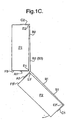
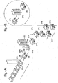
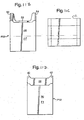
- the first package comprises two packs P1 and P2.
- the packs are closed boxes each containing cigarettes.
- the two packs are joined in a "Jacobs ladder" arrangement which allows each pack to rotate about the other as shown in Figures 1B and 1C .
- pack Pl is stationary, starting at the position shown in Figure 1A , in which the faces F1 and F1' of the two packs face one another, pack P2 is able to rotate about edge E2 of pack P1 in an anticlockwise direction.
- pack P2 is also able to rotate in a clockwise direction about edge E1 of pack P1.
- either one of the two packs can move relative to other from the position shown in Figure 1A through 180° to be side by side with the faces F1 and F1' facing in the same direction.
- either one of the two packs can move relative to other from the position shown in Figure 1A through 360° to be side by side with the faces F1 and F1' facing in opposite directions: i.e. as shown in Figure 1A but with P2 to the left of P1.
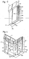
- Pack P1 is of rectangular cross section having a base, a front face F1, a rear face F2 and side faces F3 and F4 upstanding from the base. Faces F1 and F3 have an edge E1 in common; faces F1 and F4 have an edge E2 in common; faces F2 and F3 have an edge E3 in common; and Faces F2 and F4 have an edge E4 in common.
- Pack P2 is identical its faces and edges being identified by the same references as pack P1 but with a suffix '.
- Strap S1 is: fixed to P1 at face F3 and extends freely around edge E1, between and across the faces F1 and F1' to edge E2' of pack P2 and around edge E2' of P2 and is fixed at face F4' of pack P2.
- Strap S2 is fixed to P1 at face F4 and extends freely around edge E2, between and across the faces F1 and F1' to edge E1' of pack P2 and around edge E1' of pack P2 and is fixed at face F3' of pack P2.
- a minimum of two straps are needed. However, three straps may be provided, with strap S1 in between the other two straps S2 and S3, as is shown in further examples described hereinafter.
- the straps may be of any thin flexible material. If only two straps are used, then the material used is stiff transversely of the long direction of the straps. More than three straps may be provided.
- the straps have two sides and at least the parts B1 and B2 of the straps are visible in different positions of the straps and can be used for indicia and/or graphics
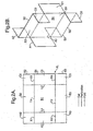
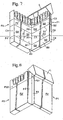
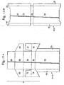
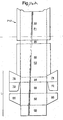
- Figures 2A and B show a blank of material which may be used to join two packs P1 and P2 using three straps S1 to S3 in a Jacobs ladder arrangement in a second example of the invention.
- Figure 2 A shows the blank before use.
- Figure 2B shows the blank folded into the configuration of its use.
- the blank is generally rectangular.
- Strap S1 is, in this example, between straps S2 and S3, and in this example is wider than each of the other two straps.
- Strap S1 comprises flaps A1 and C1 which in use are fixed to face F3 of pack P1 and face F4' of pack P2 respectively, and band B1 which extends from face F3 freely across faces F1 and F1' to face F4.
- Strap S2 comprises flaps C2 and A2 which in use are fixed to face F4 of pack P1 and face F3' of pack P2 respectively, and band B2 which extends from face F4, freely between the faces F1 and F1', to face F3'.
- strap S3 comprises flaps C3 and A3 which in use are fixed to face F4 of pack P1 and face F3' of pack P2 respectively, and band B3 which extends from face F4, freely across faces F1 and F1', to face F3'.
- Flaps A1 and A2 are separated by a cut X1.
- Flaps A1 and A3 are separated by a cut X2.
- flap C1 is separated from C2 and C3 by cuts X3 and X4.
- Band B1 is joined in the blank to bands B2 and B3 by perforated tear lines T1 and T2.
- the flaps Al to A3 and C1 to C3 are joined to the bands B1 to B3.
- the flaps are joined to the bands by fold lines L1 and L2. In other examples, such as those of film, there are no fold lines.
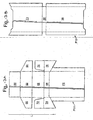
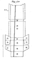
- the flaps Al to A3 and C1 to C3 may be lengthened as indicated by Al' to A3' and C1' to C3' to extend freely across faces F3, F4, F3' and F4' and be fixed to faces F2 and F2'. That allows either one of the two packs to rotate through 360° relative to the other.
- the flaps Al to A3 and C1 to C3 are fixed to the sides of the packs as shown in Figures 2A and 2B and the extensions A1' to A3' and C1' to C 3 ' are glued.
- At least one of the extensions C1' to C3' may extend over face F2' of pack P2.
- the flaps A1, A2 and A3 are adhered to the sides F4', F4, and F4 respectively of the packs P2 and P1, the extensions C1', C2' and C3' are glued.
- the extensions C1', C2' and C3' are adhered to the faces F2', F2 and F2 respectively, the flaps C1, C2 and C3 being not adhered to the sides F4', F4 and F4.
- Any one or more of the extensions C1', C2' and C3' may carry indicia and/or graphics on one or both sides thereof.
- the extensions C1', C2' and C3' could be free.
- the packs P1 and P2 may be wrapped in plastics wrapping, for example cellophane, polypropylene or other suitable material.
- the blank of Figure 2 or 3 may also be of such plastics material fixed to the plastics wrapping of the packs.
- the packs may be of card as is conventional in the art and the blank of Figure 2 or 3 may be of card or paper fixed to the card packs.
- the resulting combined package may be wrapped in plastics wrapping.
- a package as described above with reference to Figures 1 , 2A , 2B and 2C may be made in the following way.
- Packs P1 are supplied by a suitable conveyor to a station at which the joining blank JL is applied ST1 to each pack P1.
- the blanks JL are cut from a reel of material.
- the blanks JL are pre-cut and stored in a magazine. They are fed from the magazine and applied to the packs.
- the perforations and cuts may be pre-formed in the reel of material or formed at the station from plain material.
- the blank JL is adhered to the leading edge of a pack by adhering the flaps C3 and C2 of the outer straps S3 and S2 to the pack P1.
- the blank JL is then cut to length ST2.
- the first packs P1 with blanks JL adhered thereto are conveyed to a station at which second packs P2 are placed ST3 onto the blanks JL.
- the second packs P2 are fed onto the first packs P1 from one side ST3 of the conveyor.
- the second packs P2 are placed ST3' onto the first packs P1 from above ST4'.
- ST4 (or ST4') to ST8 the blank JL is adhered to the first P1 and second packs P2 to connect them in a Jacobs Ladder arrangement.
- step ST4 and ST4' the two packs P1 and P2 with the blank JL between them are indexed together, i.e. transported and accurately aligned.
- step ST5 and ST6 the two packs Pl and P 2 move vertically down through guides, or via a rotary mechanism, which fold the flaps C1, A2 and A3 upwards and in step ST7 heater bars adhere the flaps C1, A2 and A3 to the packs, hi step ST8 the packs move vertically upwards through guides which fold the remaining flap A1 down and in step ST9 flap A1 is adhered to the package by a heater bar.
- steps ST5 to ST9 may be combined wherein the vertical movement causes flaps A1, A2, A3 and C1 to fold simultaneously in the desired direction and to be adhered to the package by the heater bar.
- the fifth example is a package which comprises two packs P1 and P2 connected in a Jacobs Ladder arrangement, the two packs sharing one hinged lid.
- two packs P1 and P2 are connected together by a blank as shown in, and described with reference to, for example, Figure 2 .
- a lid L hingedly connected to one P1 of the packs closes the top of both packs P1 and P2.
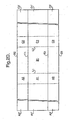
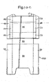
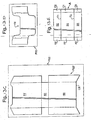
- Figures 9 , 10 and 11 show blanks which are used to construct the package.
- Figure 10A is a plan view of the joining blank JL used to join the two packs together. Joining blank JL is identical to that described with reference to Figure 2 .
- the blanks of Figures 9 to 11 are a modification of the blanks described in WO 2004/080844A1 .
- Pack P1 comprises two parts: part P11 shown in Figure 9 ; and part P12 shown in Figure 10B .
- Pack P2 comprises two parts: part P21 shown in Figure 9 ; and part P22 shown in Figure 10C .
- Figures 10B and C show the position the joining blank JL takes with respect to the blanks P12 and P22 which form parts of the packs P1 and P2.
- Parts P11 and P21 are parts of a unitary blank BL which also includes the lid L.
- Part 21 comprises a main face F2' and side faces F3' and F4'.
- Part P21 is joined to part P11 by integral flaps 78 and 80.
- the flaps 78 and 80 are joined by a tear line T3.
- Part P11 comprises a main face F2 and side faces F3 and F4.
- Part P11 is joined to the lid L via a fold line 82 which has additional weakening as indicated by 82'.
- the form of the lid is known; see for example WO 2004/080844 Al
- the lid L comprises a rear wall 84, inner side walls 74 and 76, top wall 68, and front wall 62. Flap 60 is reinforcement for the front wall and flaps 70 and 72 connect the side walls 74 and 76 to the top wall.
- the lid further comprises outer side walls 64 and 66 which are reinforced by the inner side walls 74 and 76. Fold lines between the flaps and walls are indicated by dash lines in Figure 14 .
- Part P12 is an inner part having an outer face 30 which corresponds to face F1.
- Outer face 30 is connected by a bottom wall 36 to an inner rear wall 38.
- Face 30 has side flaps 32 and 34.
- Rear wall 38 has side flaps 40 and 42.
- Part P22 is another inner part having a face 44 which corresponds to face F1' and a rear wall 56.
- the rear wall 56 is connected to the face 44 by a bottom wall 50.
- the wall 56 has side flaps 52 and 54.
- the face 44 has side flaps 46 and 48.
- the inner part P22 is assembled by folding the side flaps 46, 48, 52 and 54 at right angles to the face 44 and wall 56 along the fold lines indicated by dash lines in Figure 10C .
- the face 44 and wall 56 are folded at right angles to the bottom wall 50 along the fold lines indicated in Figure 10C .
- the side flaps 46 and 52 are glued to each other.
- the side flaps 48 and 54 are glued to each other.
- the resulting box is shown in Figure 11B .
- the inner part P12 is assembled by folding the side flaps 32, 34, 40 and 42 at right angles to the face 30 and wall 38 along the fold lines indicated by dash lines in Figure 10B .
- the face 30 and wall 38 are folded at right angles to the bottom wall 36 along the fold lines indicated in Figure 10B .
- the side flaps 40 and 34 are glued to each other.
- the side flaps 32 and 42 are glued to each other.
- the resulting box is shown in Figure 11D .
- the joining blank JL is positioned as shown in Figures 10B and C relative to the faces F1 and F1' on the inner parts P12 and P22. Flaps A2 and A3 of the joining blank are fixed to side flap 32 of the inner part P12. Flap C1 of the joining blank is fixed to side flap 34 of the inner part P12. Flaps C2 and C3 of the joining blank are fixed to side flap 48 of the inner part P22. Flap A1 of the joining blank JL is fixed to side flap 46 of the inner part P22. Then, the rear inner wall of part P22 is fixed on face F2' of the blank BL ( Fig 9 ) with the bottom wall 50 on bottom wall section 78.
- the side flaps F3'and F4' of the blank BL are glued to the side flaps of the inner part P22.
- the rear inner wall 38 of part P12 is fixed on face F2 of the blank BL with the bottom wall 36 on bottom wall section 80.
- the side flaps F3 and F4 of the blank BL are glued to the side flaps 32 and 34 of the inner part P12
- the faces 44 and 30 of the inner parts P22 and P12 respectively form the faces F1 and F1' of the packet.
- the joining blank JL may be connected directly to the side flaps F3, F3', F4 and F4' of the main blank BL.
- the inner parts P12 and P22 when assembled may slide between the faces F2 and the joining blank JL and face F2' and the joining blank JL respectively.
- the inner parts P12 and P22 will come to rest against the bottom panels 80 and 78 respectively. In this arrangement, gluing inner parts P12 and P22 directly to the main blank BL and/or joining blank JL is not necessary.
- the lid L is formed by folding inner side walls 74 and 76 together with the flaps 70 and 72 to right angles to the rear wall 84 about the fold lines at the sides of the rear wall. Flaps 70 and 72 are folded inwardly at right angles to the inner rear walls 74 and 76.. Reinforcement flap 60 is folded onto the inside of the front wall 62 and fixed to it. Top wall 68 is folded about the fold line between it and the rear wall 84 onto the flaps 70 and 72 and in this example fixed to the flaps 70 and 72. In other example the flaps 70 and 72 are free. Front wall 62 is folded down to be at right angles to the top wall. Outer side walls 64 and 66 are folded and fixed to the inner side walls 74 and 76.
- the assembled, but un-opened package has the packs P1 and P2 joined by the bottom wall sections 78 and 80 with the tear line T3 intact. Furthermore the strap S1 is joined to the straps S2 and S3 with the tear lines T1 and T2 intact.
- the package is opened by opening the lid L and rotating the pack P2 relative to pack Pl separating the bottom wall sections 78 and 80 along the tear line T3 and separating the strap S1 from strap S2 and S3 along the tear lines T1 and T2.
- the part P21 is initially separate from the part P11; ie. the blank BL is replaced by two blanks being in effect separated along the tear line T3.
- the tear line T3 remains intact during construction and is slit by machine, i.e. the line T3 is cut "online".
- the pack delivered to the consumer has separate parts P11 and P21.
- the joining blank is of such a size and is so positioned that the lid L can be opened without damaging the straps of the joining blank.
- the fifth example may be made as follows.
- the two packs P1 and P2 may be connected in the Jacobs Ladder arrangement as described with reference to Figure 4 .
- the blank of Figure 9 is folded around the joined packs P1 and P2.
- the blanks illustrated in Figures 12 to 15 may be used to make variants of the package provided by the fifth example.
- the fifth and sixth examples comprise two packs P1 and P2 connected in a Jacobs Ladder arrangement; the two packs share one hinged lid L.
- the two packs P1 and P2 are connected together with the HD section L being provided on the rear most face of the assembled pack.
- the arrangement is common to all the variants providing the eighth example.
- the differences between the variants of the sixth example is the number of and arrangement of the blanks forming the assembled package.
- Figure 12A illustrates a blank P111 which provides an outer casing to the assembled pack and also provides the lid portion L.
- the blank in Figure 12A varies from that of the sixth example by removal of the part of the outer casing provided by blank BL that covers the inner part P22 when the pack is assembled.
- Figure 12A , Figure 12C and Figure 12D correspond with Figures 10B , 10C and 10A respectively. Therefore, referring to Figures 10C and 11B , the inner part P22 is assembled by folding the side flaps 46, 48, 52 and 54 at right angles to the face 44 and wall 56 along the fold lines indicated by dash lines in Figure 10C . The face 44 and wall 56 are folded at right angles to the bottom wall 50 along the fold lines indicated in Figure 10C . The side flaps 46 and 52 are glued to each other. The side flaps 48 and 54 are glued to each other. The resulting box is shown in Figure 11B .
- the joining blank JL is positioned as indicated in Figures 10B and 10C relative to the face 30 (Fl) and 44 (Fl') on the inner parts P12 and P22 ( Figures 12B and 12C ).
- the inner part P12 is assembled by folding the side flaps 32, 34, 40 and 42 at right angles to the face 30 and wall 38 along the fold lines indicated by dash lines in Figure 15B .
- the face 30 and wall 38 are folded at right angles to the bottom wall 36 along the fold lines indicated in Figure 10B .
- the side flaps 40 and 34 are glued to each other.
- the side flaps 32 and 42 are glued to each other.
- the resulting box is shown in Figure 11D .
- the inner part assembly which comprises the inner parts P12 and P22 joined together by the joining blank JL are then attached to the blank Pill providing an outer casing and the lid L.
- the face 38 that provides the rear wall of the inner part 12 is glued to the rear face F2 of the casing blank P111.
- the face 56 of inner part P22 provides the external face of the closed package and panels 36 and 50 of inner parts P12 and P22 respectively provide the external bottom panels of the closed package.
- the lid L is formed in exactly the same was as described with reference to the sixth example. Flaps A2 and A3 of the joining blank are fixed to side flap 32 of the inner part P12. Flap C1 of the joining blank is fixed to side flap 34 of the inner part P12. Flaps C2. and C3 of the joining blank are fixed to side flap 48 of the inner part P22. Flap Al of the joining blank JL is fixed to side flap 46 of the inner part P22.
- the lid L is formed by folding inner side walls 74 and 76 together with the flaps 70 and 72 to right angles to the rear wall 84 about the fold lines at the sides of the rear wall. Flaps 70 and 72 are folded inwardly at right angles to the inner rear walls 74 and 76. Reinforcement flap 60 is folded onto the inside of the front wall 62 and fixed to it. Top wall 68 is folded about the fold line between it and the rear wall 84 onto the flaps 70 and 72 and in this example fixed to the flaps 70 and 72. In another example the flaps 70 and 72 are free. Front wall 62 is folded down to be at right angles to the top wall. Outer side walls 64 and 66 are folded and fixed to the inner side walls 74 and 76.
- a second variant of the sixth example is formed by folding and combining the blanks illustrated in Figures 13A to 13E .
- the difference between the first and second variant is that the inner part 22 is divided into two parts P22' and RL
- the inner part 22' has been modified such that the reinforcing inner insert RI is attached to the inside of face 56 that forms the interior wall of the assembled inner pack P22 such that an overlapping section is provided at CE, which overlapping section provides a closing edge CE against which the lid abuts on closing.
- the two parts forming the assembled inner part P22 (P22' and R1) provide a reinforced section such that the pack maintains its form when empty and also assists in keeping the lid closed in use.
- the package of the second variant is formed in exactly the same way as the first variant.
- Inner parts P12, P22 and joining blank JL are combined, wherein panels F2 of part P111 and 56 of part P22' form the exterior faces F2 and F2' respectively of the assembled pack.
- the lid L is formed by folding the blank in the same manner as described above and with reference to Figure 9 . Like reference numerals have been applied.
- the third variant of the sixth example dispenses with the outer casing section P111 or main blank BL as referred to above.
- the third variant is formed of three blanks as illustrated in Figures 14A , 14B and 14C .
- the lid portion L is formed as an extension of the inner part blank P12.
- the lid L is hingedly attached to the top edge of panel 38 of the inner part P12.
- the inner parts P12, P22 and the joining blank JL are combined in exactly the same way.
- the faces 38 (F2) and 56 (F2') of the inner part P12 and P22 respectively provide the external faces F2 and F2' of the assembled pack.
- Panels 36 and 50 of the inner parts P12 and P22 respectively form the external bottom faces of the assembled pack.
- the lid portion L is formed in exactly the same was as described above.
- Like reference numerals have been applied to Figure 14A as in Figure 9 , Figure 12A and Figure13A .
- the fourth variant of the sixth example is formed by folding and combining the blanks illustrated in Figures 15A to 15D .
- the blank forming inner part P22 has been divided into two parts P22' and R1
- the reinforcement insert R1 is adhered to the inside surface of the panel 56 such that an overlap is provided.
- the overlap defines a closing edge CE against which the leading closing edge of the lid abuts when closing the pack.
- the package according to the fourth variant of the sixth example is formed by first combining inner part P22' and reinforcement inner RI to form inner part P22 and joining parts P22, P12' and the joining blank JL.
- panels 38 and 56 form the exterior faces of the assembled closed pack.
- the lid is formed identically to the method described above in respect of the sixth example and the first, second and third variants of the sixth example.
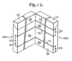
- the two packs may be conventional hinged lid packs (example seven) or they may be adapted such that the combined dimensions of the two packs HP1 and HP2 correspond with those of a single conventional hinged lid pack.
- CE of the packs HP1 and HP2 are on faces F1 and F1' such that the package is extended to access the contents of both packs.
- the packs HP1 and HP2 are comparable with inner parts P12 and P22.
- the joining blank JL is attached to each of the hinged lid packs HP1 and HP2 in the same manner as illustrated in Figures 10C and 11B .
- the side flaps C2 and C3 and Al are attached to the side panels of hinged lid pack HP2 (see Figure 16 ) and the side flaps A2 and A3 and C1 are attached to the corresponding side panels of hinged lid pack HP1.
- At least two straps are needed. As described above three straps are used. Any number of two or more straps can be used.
- Indicia and/or graphics may be provided on any of the outside walls of the package and on any face or wall of the packs in a package.
- indicia and/or graphics may be provided on the straps.
- Indicia and/or graphics may be provided on both sides of at least one of the straps.
- Packages in accordance with the invention may be used to contain objects other than smoking articles.
- the packets may be used for generally elongate cylindrical objects for example pencils and crayons.
- the packets may be used to store other objects which are not generally elongate and/or cylindrical.
- the system of combining packs of cigarettes as described herein may also be applied to combining cartons of cigarettes; a carton being the package that contains packs of cigarettes.
- a carton is usually arranged with two rows of five packs of cigarettes and provides a package having a parallelepiped shape similar to a cigarette pack.
- the strap system for combining cigarette packs may be applied to combining two or more cartons together.
- the application of the strap system to the cartons would be particularly desirable for packaging cigarette packs, which utilise the strap system, because the packaging of the carton would be indicative of the packs it contains.
- Smoking articles include cigarettes, cigars, and cigarillos amongst other such articles.
- the packages and packs contained therein described by way of example above are generally rectangular with four faces upstanding from a rectangular base.
- a pack may have two major faces upstanding from a base, the two faces meeting at two edges.
- edges are formed by faces at right angles. That is not essential to the invention: the packs and packages may have edges at least between the side walls and the front and rear walls which are rounded, bevelled, or elliptical, or other edge shapes including those known in the art.
- the cross-sectional shape of the base of the pack containing for example cigarettes may be a shape other than rectangular, for example other quadrilateral shapes such as a square.
- Two square packs may be combined with the strap system described above to provide a package having a rectangular base comprised of two squares arranged side-by side.
- a three sided polygon may be applicable, that is to say a triangle.
- a triangular shaped base provides a suitable container for holding objects such as cigarettes.
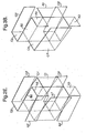
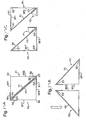
- An example of a triangular shaped-base is illustrated in figures 17A, 17B and 17C .
- the triangular based packs Pl and P2 are illustrated simply in cross section.
- the packs are combined utilising the strap system described above.
- the first face Fl and Fl' of the first and second packs Pl and P2 respectively face each other such that the combined arrangement forms a package having a square base.
- the strap system is applied to the packs by fixing one end of the first strap S1 to the side face SF1, extending the strap around the first edge E1 that adjoins the first side face SF1 to the first face F1, extending across the faces F1 and F1' that are facing each other and around the second edge E2' of the second pack P2 and fixing the strap to the second side face SF2' of the second pack P2.
- the second strap is arranged by fixing one end to the first side face SF1' of the second pack P2, passing the strap around edge E1' across the first faces F1 and F1' and around the second edge E2 of the first pack Pl and affixing the strap to the second side face SF2 of the first pack.
- the arrangement of the packs P1 and P2 is changeable from the package having a square cross section, comprised of two triangles, to a package having a triangular cross section ( Figure 17B ).
- FIG 17C A further example of applying the strap system to triangular shaped packs P1 and P2 is illustrated in Figure 17C .
- the two packs are arranged to form a package having a square cross section.
- the first strap S1 in the first position the first strap S1 is fixed at the second side face SF2 that adjoins the third edge E3 of the first pack Pl.
- the first strap S1 extends across the first side face SF1 of the first pack P1, around the first edge E1 of the first pack P1 and across the first face F1 and F1' of both packs around the second edge E2' of the second pack P2 and is fixed at the second side face SF2' of the second pack P2.
- the second strap S2 is fixed at the second side face SF2' of the second pack P2 and extends around the third edge E3' of the second pack P2, across the first side face SF1' of the second pack P2, around the first edge E1' of the second pack P2, across the first faces F1, F1' of both the first and second packs and around the second edge E2 of the first pack P1.
- the end of the second strap S2 is then fixed at the second side face SF2 of the first pack.
- the arrangement of the straps provides for the first strap S1 being hinged about the first edge E1' of the second pack P2 and the first E1 and third edges E3 of the first pack P1.
- the second strap S2 is hinged about the second edge E2 of the first pack P1 and the first E1' and third edges E3' of the second pack P2.
- the first and second packs P1, P2 are movable relative to each other from the first position to the position illustrated in Figure 17B , wherein the second pack P2 is rotated relative to the first pack P1 about the second edge E2, or alternatively the packs are able to reach the same position by rotating the first pack P1 relative to the second pack P2 about the first edge E1 and the third edge E3.
- Such packs have a base from which upstand faces and edges. The edges tend to be rounded. The faces and edges are not rigid.
- the Jacobs ladder arrangement may be applied to soft cup packs. Some examples of such packs have a tear tape around or near the top of the pack.
- the straps of the Jacobs Ladder arrangement are arranged relative to the openings of the packs so that the packs maybe opened without damaging or breaking the straps.
- Tobacco pouches are generally formed of two laminated sheets heat-sealed about their periphery with one edge open into which contents are placed.
- the principle of the invention may be applied to connecting more than two packs. For example three packs may be connected.
Landscapes
- Engineering & Computer Science (AREA)
- Mechanical Engineering (AREA)
- Packaging Of Annular Or Rod-Shaped Articles, Wearing Apparel, Cassettes, Or The Like (AREA)
- Cartons (AREA)
- Making Paper Articles (AREA)
- Wrapping Of Specific Fragile Articles (AREA)
- Packages (AREA)
- Package Specialized In Special Use (AREA)
- Basic Packing Technique (AREA)
- Bag Frames (AREA)
Applications Claiming Priority (2)
| Application Number | Priority Date | Filing Date | Title |
|---|---|---|---|
| GBGB0501733.0A GB0501733D0 (en) | 2005-01-27 | 2005-01-27 | Packages |
| PCT/GB2006/000245 WO2006079799A1 (en) | 2005-01-27 | 2006-01-25 | Packages |
Publications (2)
| Publication Number | Publication Date |
|---|---|
| EP1841657A1 EP1841657A1 (en) | 2007-10-10 |
| EP1841657B1 true EP1841657B1 (en) | 2015-05-27 |
Family
ID=34259787
Family Applications (1)
| Application Number | Title | Priority Date | Filing Date |
|---|---|---|---|
| EP06703163.3A Active EP1841657B1 (en) | 2005-01-27 | 2006-01-25 | Packages |
Country Status (18)
| Country | Link |
|---|---|
| US (4) | US20090230004A1 (enExample) |
| EP (1) | EP1841657B1 (enExample) |
| JP (1) | JP5122977B2 (enExample) |
| KR (2) | KR100974715B1 (enExample) |
| CN (1) | CN101107172B (enExample) |
| AR (1) | AR059460A1 (enExample) |
| AU (2) | AU2006208922B2 (enExample) |
| BR (1) | BRPI0606771B1 (enExample) |
| CA (1) | CA2592613C (enExample) |
| GB (1) | GB0501733D0 (enExample) |
| MX (1) | MX2007009138A (enExample) |
| MY (1) | MY140753A (enExample) |
| NZ (1) | NZ556312A (enExample) |
| RU (3) | RU2422341C1 (enExample) |
| TW (1) | TWI365158B (enExample) |
| UA (1) | UA92162C2 (enExample) |
| WO (1) | WO2006079799A1 (enExample) |
| ZA (1) | ZA200705755B (enExample) |
Families Citing this family (39)
| Publication number | Priority date | Publication date | Assignee | Title |
|---|---|---|---|---|
| GB0305661D0 (en) * | 2003-03-12 | 2003-04-16 | British American Tobacco Co | Smoking article pack blank(s) |
| GB2439066A (en) * | 2006-06-16 | 2007-12-19 | Field Group Plc | Container with hinged interconnected compartments enclosed by lid |
| GB0614942D0 (en) | 2006-07-27 | 2006-09-06 | British American Tobacco Co | Apparatus and method for packing smoking articles |
| WO2008019841A2 (de) * | 2006-08-17 | 2008-02-21 | Wilhelm Steinbach | Bedruckter oder bedruckbarer informationsträger |
| US7621398B2 (en) * | 2007-04-11 | 2009-11-24 | 3M Innovative Properties Company | Portable housing container |
| EP2017180A1 (en) * | 2007-07-20 | 2009-01-21 | Philip Morris Products S.A. | Double pack with integral connector |
| EP2017196A1 (en) * | 2007-07-20 | 2009-01-21 | Philip Morris Products S.A. | Two pack package with connector |
| EP2017197A1 (en) | 2007-07-20 | 2009-01-21 | Philip Morris Products S.A. | Package with double hinged connector |
| TWI616707B (zh) | 2008-11-28 | 2018-03-01 | 半導體能源研究所股份有限公司 | 液晶顯示裝置 |
| CN102473734B (zh) | 2009-07-31 | 2015-08-12 | 株式会社半导体能源研究所 | 半导体装置及其制造方法 |
| KR20190066086A (ko) | 2009-11-06 | 2019-06-12 | 가부시키가이샤 한도오따이 에네루기 켄큐쇼 | 반도체 장치 및 그 제작 방법 |
| JP4965639B2 (ja) * | 2009-12-18 | 2012-07-04 | 善徳 徂徠 | 物品保持具 |
| KR101399610B1 (ko) | 2010-02-05 | 2014-05-27 | 가부시키가이샤 한도오따이 에네루기 켄큐쇼 | 반도체 장치, 및 반도체 장치의 제조 방법 |
| US8835917B2 (en) | 2010-09-13 | 2014-09-16 | Semiconductor Energy Laboratory Co., Ltd. | Semiconductor device, power diode, and rectifier |
| IT1401949B1 (it) * | 2010-09-21 | 2013-08-28 | Perfetti Van Melle Spa | Confezione pieghevole a portafoglio per prodotti dolciari, in particolare barrette o lastre di gomma da masticare. |
| EP2548808A1 (en) | 2011-07-18 | 2013-01-23 | Philip Morris Products S.A. | Container with integrally connected receptacles |
| US20140314916A1 (en) * | 2011-11-08 | 2014-10-23 | Conopco, Inc. D/B/A Unilever | Carton |
| CN102406358A (zh) * | 2011-12-22 | 2012-04-11 | 郑荣昊 | 储物凳 |
| WO2013092271A1 (en) | 2011-12-22 | 2013-06-27 | Philip Morris Products S.A. | Container with receptacles connected by hinged connector |
| GB201205243D0 (en) | 2012-03-26 | 2012-05-09 | Kraft Foods R & D Inc | Packaging and method of opening |
| US9059219B2 (en) | 2012-06-27 | 2015-06-16 | Semiconductor Energy Laboratory Co., Ltd. | Semiconductor device and method for manufacturing semiconductor device |
| CN102910338B (zh) | 2012-10-11 | 2015-09-30 | 友达光电股份有限公司 | 包装盒 |
| KR101632854B1 (ko) | 2012-10-17 | 2016-06-22 | 니뽄 다바코 산교 가부시키가이샤 | 하드형 패키지 |
| EP2727852B1 (en) * | 2012-11-03 | 2016-02-03 | Reemtsma Cigarettenfabriken GmbH | Package for tobacco related articles having slidable compartments |
| KR102798241B1 (ko) | 2012-12-25 | 2025-04-22 | 가부시키가이샤 한도오따이 에네루기 켄큐쇼 | 반도체 장치 |
| US9086845B2 (en) * | 2013-02-26 | 2015-07-21 | Superior Communications, Inc. | Folio case |
| GB2511560B (en) | 2013-03-07 | 2018-11-14 | Mondelez Uk R&D Ltd | Improved Packaging and Method of Forming Packaging |
| GB2511559B (en) | 2013-03-07 | 2018-11-14 | Mondelez Uk R&D Ltd | Improved Packaging and Method of Forming Packaging |
| ITBO20130023U1 (it) * | 2013-03-15 | 2014-09-16 | Gima Spa | Confezione. |
| JP2016001712A (ja) | 2013-11-29 | 2016-01-07 | 株式会社半導体エネルギー研究所 | 半導体装置の作製方法 |
| KR102283814B1 (ko) | 2013-12-25 | 2021-07-29 | 가부시키가이샤 한도오따이 에네루기 켄큐쇼 | 반도체 장치 |
| KR20220163502A (ko) | 2013-12-26 | 2022-12-09 | 가부시키가이샤 한도오따이 에네루기 켄큐쇼 | 반도체 장치 |
| SG11201606647PA (en) | 2014-03-14 | 2016-09-29 | Semiconductor Energy Lab Co Ltd | Circuit system |
| TWI672804B (zh) | 2014-05-23 | 2019-09-21 | 日商半導體能源研究所股份有限公司 | 半導體裝置的製造方法 |
| USD795083S1 (en) * | 2015-04-07 | 2017-08-22 | Sergei Safiullin | Dual chamber packaging |
| US11661268B2 (en) * | 2015-10-26 | 2023-05-30 | R.J. Reynolds Tobacco Company | Product package |
| US9790020B1 (en) | 2016-04-12 | 2017-10-17 | R. J. Reynolds Tobacco Company | Packaging container for a tobacco product |
| CN105800025B (zh) * | 2016-05-18 | 2018-06-19 | 天津商业大学 | 一种八联包包装盒 |
| CN110254885B (zh) * | 2019-06-17 | 2020-12-29 | 浙江理工大学 | 一种翻盖式一体两箱盒 |
Citations (2)
| Publication number | Priority date | Publication date | Assignee | Title |
|---|---|---|---|---|
| US2320006A (en) * | 1940-04-29 | 1943-05-25 | Moore Francis Lee | Container |
| JPH0534114U (ja) * | 1991-09-30 | 1993-05-07 | 大日本印刷株式会社 | からくり函 |
Family Cites Families (37)
| Publication number | Priority date | Publication date | Assignee | Title |
|---|---|---|---|---|
| SU28871A1 (ru) * | 1927-11-29 | 1932-12-31 | Молинс В.Э. | Папиросна коробка |
| US1906742A (en) * | 1929-03-11 | 1933-05-02 | Coulapides Anthony | Cigarette container |
| GB351028A (en) | 1930-02-18 | 1931-06-18 | Walter Everett Molins | Improvements in or relating to cartons for cigarettes and like articles |
| US1850410A (en) | 1930-08-04 | 1932-03-22 | Andrew M Spinks | Reload cigarette package |
| US2046484A (en) | 1932-09-14 | 1936-07-07 | Carton Container Company | Duplex container |
| GB425715A (en) * | 1933-12-13 | 1935-03-20 | Walter Everett Molins | Improvements in or relating to wrapping or packing articles |
| US2133155A (en) * | 1936-12-12 | 1938-10-11 | Corwin W Stevens | Advertising device |
| US2245875A (en) * | 1939-12-04 | 1941-06-17 | Norman F Rutherford | Toy |
| US2310711A (en) * | 1942-10-14 | 1943-02-09 | Edward S Savage | Mystery toy |
| US2809467A (en) * | 1955-06-24 | 1957-10-15 | Pierre George L St | Articulated toy |
| US2959338A (en) * | 1956-11-14 | 1960-11-08 | Gerald E Thurston | Package |
| US3143266A (en) | 1961-10-04 | 1964-08-04 | Imatake Midorl | Self-tightening article carrier |
| US3226010A (en) * | 1963-11-26 | 1965-12-28 | Jr Ford Rogers | Cigarette packaging |
| FR1496551A (fr) * | 1966-10-13 | 1967-09-29 | Molins Machine Co Ltd | Perfectionnements aux emballages, notamment de cigarettes |
| US3530614A (en) * | 1967-08-03 | 1970-09-29 | Toplay Products Inc | Toy |
| US4095366A (en) * | 1976-10-08 | 1978-06-20 | John Kenneth Buck | Block puzzle toy |
| DE7901873U1 (de) * | 1979-01-24 | 1979-05-10 | Focke & Co | Verpackung aus faltbarem Material insbesondere fuer Zigaretten |
| DE3313462A1 (de) * | 1983-04-14 | 1984-10-18 | Focke & Co, 2810 Verden | Verpackung fuer eine mehrzahl von zigaretten-packungen oder dergleichen (zigarettenstange) |
| US4657248A (en) * | 1985-08-07 | 1987-04-14 | Prosper Benaim | Question-and-answer game |
| EP0248927B1 (de) * | 1986-06-10 | 1989-08-30 | Focke & Co. (GmbH & Co.) | Packung aus Schieber und Hülse |
| FR2614720B1 (fr) | 1987-04-29 | 1992-06-26 | Widmann Horst | Conditionnement a double effet publicitaire apparent et non apparent |
| US4850482A (en) * | 1988-06-10 | 1989-07-25 | Philip Morris Incorporated | Cigarette box innerframe |
| JP2908479B2 (ja) | 1989-08-30 | 1999-06-21 | ポリプラスチックス株式会社 | ポリエステル樹脂組成物並びにその製造法 |
| US5261533A (en) * | 1992-02-07 | 1993-11-16 | Philip Morris Inc. | Tax-stampable half-carton |
| JPH05278757A (ja) * | 1992-04-02 | 1993-10-26 | Nkk Corp | 積層金属シート梱包体 |
| DE4311222A1 (de) * | 1993-04-05 | 1994-10-06 | Hans Prof Roericht | Behälter zur Aufnahme von Gegenständen |
| US5344008A (en) * | 1993-06-02 | 1994-09-06 | Philip Morris Incorporated | Packaging for articles such as cigarettes |
| JPH0743632U (ja) * | 1993-07-31 | 1995-09-05 | 有限会社太陽物産 | 図画が変化する連結された容器 |
| US5701696A (en) * | 1995-06-07 | 1997-12-30 | Clontz; Richard C. | Card holder |
| US5628670A (en) * | 1995-09-21 | 1997-05-13 | Hill; Allan F. | Toy consisting of interconnected hinged blocks |
| US6363691B1 (en) * | 1999-09-23 | 2002-04-02 | Brown & Williamson Tobacco Corporation | Method of wrapping a package having a corona treated tear tape |
| CN2480326Y (zh) * | 2001-03-06 | 2002-03-06 | 赵剑峰 | 带火柴的三折香烟盒 |
| CN2490105Y (zh) * | 2001-08-09 | 2002-05-08 | 殷保平 | 安全、卫生型香烟盒 |
| CN2584561Y (zh) * | 2002-11-15 | 2003-11-05 | 林荣哲 | 双盖烟盒 |
| JP4035603B2 (ja) * | 2002-12-27 | 2008-01-23 | 株式会社キョウセイテックコンサルタント | 両面開きの帳綴り |
| GB0305661D0 (en) | 2003-03-12 | 2003-04-16 | British American Tobacco Co | Smoking article pack blank(s) |
| WO2005007537A1 (en) * | 2003-07-16 | 2005-01-27 | Philip Morris Products S.A. | Cigarette pack comprising twin cigarette packets |
-
2005
- 2005-01-27 GB GBGB0501733.0A patent/GB0501733D0/en not_active Ceased
-
2006
- 2006-01-25 US US11/795,742 patent/US20090230004A1/en not_active Abandoned
- 2006-01-25 JP JP2007552711A patent/JP5122977B2/ja not_active Expired - Fee Related
- 2006-01-25 MX MX2007009138A patent/MX2007009138A/es active IP Right Grant
- 2006-01-25 NZ NZ556312A patent/NZ556312A/en not_active IP Right Cessation
- 2006-01-25 KR KR1020077019547A patent/KR100974715B1/ko not_active Expired - Fee Related
- 2006-01-25 AU AU2006208922A patent/AU2006208922B2/en not_active Ceased
- 2006-01-25 KR KR1020107010919A patent/KR101141480B1/ko not_active Expired - Fee Related
- 2006-01-25 RU RU2009143976/12A patent/RU2422341C1/ru not_active IP Right Cessation
- 2006-01-25 RU RU2007132256/12A patent/RU2383478C2/ru not_active IP Right Cessation
- 2006-01-25 WO PCT/GB2006/000245 patent/WO2006079799A1/en not_active Ceased
- 2006-01-25 CN CN2006800031126A patent/CN101107172B/zh not_active Expired - Fee Related
- 2006-01-25 BR BRPI0606771-9A patent/BRPI0606771B1/pt not_active IP Right Cessation
- 2006-01-25 CA CA2592613A patent/CA2592613C/en not_active Expired - Fee Related
- 2006-01-25 EP EP06703163.3A patent/EP1841657B1/en active Active
- 2006-01-25 UA UAA200709350A patent/UA92162C2/ru unknown
- 2006-01-26 MY MYPI20060362A patent/MY140753A/en unknown
- 2006-01-26 TW TW095102966A patent/TWI365158B/zh not_active IP Right Cessation
- 2006-01-27 AR ARP060100320A patent/AR059460A1/es active IP Right Grant
-
2007
- 2007-07-12 ZA ZA200705755A patent/ZA200705755B/xx unknown
-
2009
- 2009-11-27 RU RU2011108227/12A patent/RU2459754C1/ru not_active IP Right Cessation
-
2010
- 2010-11-29 AU AU2010246494A patent/AU2010246494A1/en not_active Abandoned
-
2011
- 2011-05-12 US US13/106,341 patent/US8413805B2/en not_active Expired - Fee Related
-
2013
- 2013-03-07 US US13/788,457 patent/US20130248393A1/en not_active Abandoned
-
2014
- 2014-03-13 US US14/208,715 patent/US20140246344A1/en not_active Abandoned
Patent Citations (2)
| Publication number | Priority date | Publication date | Assignee | Title |
|---|---|---|---|---|
| US2320006A (en) * | 1940-04-29 | 1943-05-25 | Moore Francis Lee | Container |
| JPH0534114U (ja) * | 1991-09-30 | 1993-05-07 | 大日本印刷株式会社 | からくり函 |
Also Published As
Similar Documents
| Publication | Publication Date | Title |
|---|---|---|
| EP1841657B1 (en) | Packages | |
| EP3237305B1 (en) | Container with customisable opening-and-closing mechanism of inner package | |
| US9072320B2 (en) | Multi-compartment package and related method, blank and assembly | |
| RU2349522C2 (ru) | Заготовка(и) упаковки курительных изделий | |
| US8205751B2 (en) | Folding packet | |
| EP2192045A1 (en) | Slide and shell container | |
| HK1115567B (en) | Packages | |
| WO2025104542A1 (en) | Sealed packaging for consumer products and its manufacturing method | |
| WO2011138681A1 (en) | Container having cut-out portion |
Legal Events
| Date | Code | Title | Description |
|---|---|---|---|
| PUAI | Public reference made under article 153(3) epc to a published international application that has entered the european phase |
Free format text: ORIGINAL CODE: 0009012 |
|
| 17P | Request for examination filed |
Effective date: 20070809 |
|
| AK | Designated contracting states |
Kind code of ref document: A1 Designated state(s): AT BE BG CH CY CZ DE DK EE ES FI FR GB GR HU IE IS IT LI LT LU LV MC NL PL PT RO SE SI SK TR |
|
| AX | Request for extension of the european patent |
Extension state: YU |
|
| RAX | Requested extension states of the european patent have changed |
Extension state: YU Payment date: 20070809 |
|
| 17Q | First examination report despatched |
Effective date: 20121122 |
|
| GRAP | Despatch of communication of intention to grant a patent |
Free format text: ORIGINAL CODE: EPIDOSNIGR1 |
|
| INTG | Intention to grant announced |
Effective date: 20141105 |
|
| GRAS | Grant fee paid |
Free format text: ORIGINAL CODE: EPIDOSNIGR3 |
|
| GRAP | Despatch of communication of intention to grant a patent |
Free format text: ORIGINAL CODE: EPIDOSNIGR1 |
|
| INTG | Intention to grant announced |
Effective date: 20150331 |
|
| GRAA | (expected) grant |
Free format text: ORIGINAL CODE: 0009210 |
|
| AK | Designated contracting states |
Kind code of ref document: B1 Designated state(s): AT BE BG CH CY CZ DE DK EE ES FI FR GB GR HU IE IS IT LI LT LU LV MC NL PL PT RO SE SI SK TR |
|
| AX | Request for extension of the european patent |
Extension state: YU |
|
| REG | Reference to a national code |
Ref country code: GB Ref legal event code: FG4D |
|
| REG | Reference to a national code |
Ref country code: CH Ref legal event code: EP |
|
| REG | Reference to a national code |
Ref country code: AT Ref legal event code: REF Ref document number: 728704 Country of ref document: AT Kind code of ref document: T Effective date: 20150615 |
|
| REG | Reference to a national code |
Ref country code: IE Ref legal event code: FG4D |
|
| REG | Reference to a national code |
Ref country code: DE Ref legal event code: R096 Ref document number: 602006045521 Country of ref document: DE |
|
| REG | Reference to a national code |
Ref country code: AT Ref legal event code: MK05 Ref document number: 728704 Country of ref document: AT Kind code of ref document: T Effective date: 20150527 |
|
| REG | Reference to a national code |
Ref country code: LT Ref legal event code: MG4D |
|
| PG25 | Lapsed in a contracting state [announced via postgrant information from national office to epo] |
Ref country code: ES Free format text: LAPSE BECAUSE OF FAILURE TO SUBMIT A TRANSLATION OF THE DESCRIPTION OR TO PAY THE FEE WITHIN THE PRESCRIBED TIME-LIMIT Effective date: 20150527 Ref country code: PT Free format text: LAPSE BECAUSE OF FAILURE TO SUBMIT A TRANSLATION OF THE DESCRIPTION OR TO PAY THE FEE WITHIN THE PRESCRIBED TIME-LIMIT Effective date: 20150928 Ref country code: FI Free format text: LAPSE BECAUSE OF FAILURE TO SUBMIT A TRANSLATION OF THE DESCRIPTION OR TO PAY THE FEE WITHIN THE PRESCRIBED TIME-LIMIT Effective date: 20150527 Ref country code: LT Free format text: LAPSE BECAUSE OF FAILURE TO SUBMIT A TRANSLATION OF THE DESCRIPTION OR TO PAY THE FEE WITHIN THE PRESCRIBED TIME-LIMIT Effective date: 20150527 |
|
| REG | Reference to a national code |
Ref country code: NL Ref legal event code: MP Effective date: 20150527 |
|
| PG25 | Lapsed in a contracting state [announced via postgrant information from national office to epo] |
Ref country code: BG Free format text: LAPSE BECAUSE OF FAILURE TO SUBMIT A TRANSLATION OF THE DESCRIPTION OR TO PAY THE FEE WITHIN THE PRESCRIBED TIME-LIMIT Effective date: 20150827 Ref country code: IS Free format text: LAPSE BECAUSE OF FAILURE TO SUBMIT A TRANSLATION OF THE DESCRIPTION OR TO PAY THE FEE WITHIN THE PRESCRIBED TIME-LIMIT Effective date: 20150927 Ref country code: AT Free format text: LAPSE BECAUSE OF FAILURE TO SUBMIT A TRANSLATION OF THE DESCRIPTION OR TO PAY THE FEE WITHIN THE PRESCRIBED TIME-LIMIT Effective date: 20150527 Ref country code: LV Free format text: LAPSE BECAUSE OF FAILURE TO SUBMIT A TRANSLATION OF THE DESCRIPTION OR TO PAY THE FEE WITHIN THE PRESCRIBED TIME-LIMIT Effective date: 20150527 Ref country code: GR Free format text: LAPSE BECAUSE OF FAILURE TO SUBMIT A TRANSLATION OF THE DESCRIPTION OR TO PAY THE FEE WITHIN THE PRESCRIBED TIME-LIMIT Effective date: 20150828 |
|
| PG25 | Lapsed in a contracting state [announced via postgrant information from national office to epo] |
Ref country code: DK Free format text: LAPSE BECAUSE OF FAILURE TO SUBMIT A TRANSLATION OF THE DESCRIPTION OR TO PAY THE FEE WITHIN THE PRESCRIBED TIME-LIMIT Effective date: 20150527 Ref country code: EE Free format text: LAPSE BECAUSE OF FAILURE TO SUBMIT A TRANSLATION OF THE DESCRIPTION OR TO PAY THE FEE WITHIN THE PRESCRIBED TIME-LIMIT Effective date: 20150527 |
|
| PG25 | Lapsed in a contracting state [announced via postgrant information from national office to epo] |
Ref country code: RO Free format text: LAPSE BECAUSE OF NON-PAYMENT OF DUE FEES Effective date: 20150527 Ref country code: CZ Free format text: LAPSE BECAUSE OF FAILURE TO SUBMIT A TRANSLATION OF THE DESCRIPTION OR TO PAY THE FEE WITHIN THE PRESCRIBED TIME-LIMIT Effective date: 20150527 Ref country code: SK Free format text: LAPSE BECAUSE OF FAILURE TO SUBMIT A TRANSLATION OF THE DESCRIPTION OR TO PAY THE FEE WITHIN THE PRESCRIBED TIME-LIMIT Effective date: 20150527 Ref country code: PL Free format text: LAPSE BECAUSE OF FAILURE TO SUBMIT A TRANSLATION OF THE DESCRIPTION OR TO PAY THE FEE WITHIN THE PRESCRIBED TIME-LIMIT Effective date: 20150527 |
|
| REG | Reference to a national code |
Ref country code: DE Ref legal event code: R097 Ref document number: 602006045521 Country of ref document: DE |
|
| PLBE | No opposition filed within time limit |
Free format text: ORIGINAL CODE: 0009261 |
|
| STAA | Information on the status of an ep patent application or granted ep patent |
Free format text: STATUS: NO OPPOSITION FILED WITHIN TIME LIMIT |
|
| PG25 | Lapsed in a contracting state [announced via postgrant information from national office to epo] |
Ref country code: IT Free format text: LAPSE BECAUSE OF FAILURE TO SUBMIT A TRANSLATION OF THE DESCRIPTION OR TO PAY THE FEE WITHIN THE PRESCRIBED TIME-LIMIT Effective date: 20150527 |
|
| 26N | No opposition filed |
Effective date: 20160301 |
|
| PG25 | Lapsed in a contracting state [announced via postgrant information from national office to epo] |
Ref country code: SI Free format text: LAPSE BECAUSE OF FAILURE TO SUBMIT A TRANSLATION OF THE DESCRIPTION OR TO PAY THE FEE WITHIN THE PRESCRIBED TIME-LIMIT Effective date: 20150527 Ref country code: BE Free format text: LAPSE BECAUSE OF NON-PAYMENT OF DUE FEES Effective date: 20160131 |
|
| PG25 | Lapsed in a contracting state [announced via postgrant information from national office to epo] |
Ref country code: BE Free format text: LAPSE BECAUSE OF FAILURE TO SUBMIT A TRANSLATION OF THE DESCRIPTION OR TO PAY THE FEE WITHIN THE PRESCRIBED TIME-LIMIT Effective date: 20150527 Ref country code: LU Free format text: LAPSE BECAUSE OF FAILURE TO SUBMIT A TRANSLATION OF THE DESCRIPTION OR TO PAY THE FEE WITHIN THE PRESCRIBED TIME-LIMIT Effective date: 20160125 |
|
| REG | Reference to a national code |
Ref country code: CH Ref legal event code: PL |
|
| PG25 | Lapsed in a contracting state [announced via postgrant information from national office to epo] |
Ref country code: MC Free format text: LAPSE BECAUSE OF FAILURE TO SUBMIT A TRANSLATION OF THE DESCRIPTION OR TO PAY THE FEE WITHIN THE PRESCRIBED TIME-LIMIT Effective date: 20150527 |
|
| REG | Reference to a national code |
Ref country code: FR Ref legal event code: ST Effective date: 20160930 |
|
| PG25 | Lapsed in a contracting state [announced via postgrant information from national office to epo] |
Ref country code: LI Free format text: LAPSE BECAUSE OF NON-PAYMENT OF DUE FEES Effective date: 20160131 Ref country code: CH Free format text: LAPSE BECAUSE OF NON-PAYMENT OF DUE FEES Effective date: 20160131 |
|
| REG | Reference to a national code |
Ref country code: IE Ref legal event code: MM4A |
|
| PG25 | Lapsed in a contracting state [announced via postgrant information from national office to epo] |
Ref country code: FR Free format text: LAPSE BECAUSE OF NON-PAYMENT OF DUE FEES Effective date: 20160201 |
|
| PG25 | Lapsed in a contracting state [announced via postgrant information from national office to epo] |
Ref country code: IE Free format text: LAPSE BECAUSE OF NON-PAYMENT OF DUE FEES Effective date: 20160125 |
|
| PG25 | Lapsed in a contracting state [announced via postgrant information from national office to epo] |
Ref country code: SE Free format text: LAPSE BECAUSE OF FAILURE TO SUBMIT A TRANSLATION OF THE DESCRIPTION OR TO PAY THE FEE WITHIN THE PRESCRIBED TIME-LIMIT Effective date: 20150527 Ref country code: NL Free format text: LAPSE BECAUSE OF FAILURE TO SUBMIT A TRANSLATION OF THE DESCRIPTION OR TO PAY THE FEE WITHIN THE PRESCRIBED TIME-LIMIT Effective date: 20150527 |
|
| PGFP | Annual fee paid to national office [announced via postgrant information from national office to epo] |
Ref country code: GB Payment date: 20180119 Year of fee payment: 13 Ref country code: DE Payment date: 20180122 Year of fee payment: 13 |
|
| PG25 | Lapsed in a contracting state [announced via postgrant information from national office to epo] |
Ref country code: CY Free format text: LAPSE BECAUSE OF FAILURE TO SUBMIT A TRANSLATION OF THE DESCRIPTION OR TO PAY THE FEE WITHIN THE PRESCRIBED TIME-LIMIT Effective date: 20150527 Ref country code: HU Free format text: LAPSE BECAUSE OF FAILURE TO SUBMIT A TRANSLATION OF THE DESCRIPTION OR TO PAY THE FEE WITHIN THE PRESCRIBED TIME-LIMIT; INVALID AB INITIO Effective date: 20060125 |
|
| PGFP | Annual fee paid to national office [announced via postgrant information from national office to epo] |
Ref country code: TR Payment date: 20180123 Year of fee payment: 13 |
|
| REG | Reference to a national code |
Ref country code: DE Ref legal event code: R119 Ref document number: 602006045521 Country of ref document: DE |
|
| GBPC | Gb: european patent ceased through non-payment of renewal fee |
Effective date: 20190125 |
|
| PG25 | Lapsed in a contracting state [announced via postgrant information from national office to epo] |
Ref country code: DE Free format text: LAPSE BECAUSE OF NON-PAYMENT OF DUE FEES Effective date: 20190801 |
|
| PG25 | Lapsed in a contracting state [announced via postgrant information from national office to epo] |
Ref country code: GB Free format text: LAPSE BECAUSE OF NON-PAYMENT OF DUE FEES Effective date: 20190125 |
|
| PG25 | Lapsed in a contracting state [announced via postgrant information from national office to epo] |
Ref country code: TR Free format text: LAPSE BECAUSE OF NON-PAYMENT OF DUE FEES Effective date: 20190125 |