EP1841112A1 - Methode de transmission et appareil de transmission dans un systeme de communication ofdm-cdma - Google Patents
Methode de transmission et appareil de transmission dans un systeme de communication ofdm-cdma Download PDFInfo
- Publication number
- EP1841112A1 EP1841112A1 EP05703755A EP05703755A EP1841112A1 EP 1841112 A1 EP1841112 A1 EP 1841112A1 EP 05703755 A EP05703755 A EP 05703755A EP 05703755 A EP05703755 A EP 05703755A EP 1841112 A1 EP1841112 A1 EP 1841112A1
- Authority
- EP
- European Patent Office
- Prior art keywords
- subcarrier
- subcarriers
- ofdm
- cdma communication
- subcarrier components
- Prior art date
- Legal status (The legal status is an assumption and is not a legal conclusion. Google has not performed a legal analysis and makes no representation as to the accuracy of the status listed.)
- Granted
Links
- 238000004891 communication Methods 0.000 title claims abstract description 97
- 238000000034 method Methods 0.000 title claims description 37
- 230000005540 biological transmission Effects 0.000 claims abstract description 91
- 108010003272 Hyaluronate lyase Proteins 0.000 claims abstract description 40
- 230000007480 spreading Effects 0.000 claims description 67
- 238000005562 fading Methods 0.000 claims description 50
- 238000005259 measurement Methods 0.000 claims description 8
- 239000000284 extract Substances 0.000 claims 1
- 238000012544 monitoring process Methods 0.000 claims 1
- 230000008707 rearrangement Effects 0.000 description 19
- 238000010276 construction Methods 0.000 description 17
- 238000006243 chemical reaction Methods 0.000 description 8
- 230000000694 effects Effects 0.000 description 6
- 238000001514 detection method Methods 0.000 description 3
- 230000006866 deterioration Effects 0.000 description 3
- 238000012545 processing Methods 0.000 description 3
- 238000005070 sampling Methods 0.000 description 3
- 230000009466 transformation Effects 0.000 description 3
- 230000002411 adverse Effects 0.000 description 2
- 238000003780 insertion Methods 0.000 description 2
- 230000037431 insertion Effects 0.000 description 2
- 238000010295 mobile communication Methods 0.000 description 2
- 230000003321 amplification Effects 0.000 description 1
- 230000008859 change Effects 0.000 description 1
- 238000007796 conventional method Methods 0.000 description 1
- 230000003247 decreasing effect Effects 0.000 description 1
- 230000006872 improvement Effects 0.000 description 1
- 231100000989 no adverse effect Toxicity 0.000 description 1
- 238000003199 nucleic acid amplification method Methods 0.000 description 1
- 238000011160 research Methods 0.000 description 1
Images


Classifications
-
- H—ELECTRICITY
- H04—ELECTRIC COMMUNICATION TECHNIQUE
- H04L—TRANSMISSION OF DIGITAL INFORMATION, e.g. TELEGRAPHIC COMMUNICATION
- H04L5/00—Arrangements affording multiple use of the transmission path
- H04L5/0001—Arrangements for dividing the transmission path
- H04L5/0014—Three-dimensional division
- H04L5/0016—Time-frequency-code
- H04L5/0019—Time-frequency-code in which one code is applied, as a temporal sequence, to all frequencies
-
- H—ELECTRICITY
- H04—ELECTRIC COMMUNICATION TECHNIQUE
- H04L—TRANSMISSION OF DIGITAL INFORMATION, e.g. TELEGRAPHIC COMMUNICATION
- H04L1/00—Arrangements for detecting or preventing errors in the information received
- H04L1/0001—Systems modifying transmission characteristics according to link quality, e.g. power backoff
- H04L1/0002—Systems modifying transmission characteristics according to link quality, e.g. power backoff by adapting the transmission rate
- H04L1/0003—Systems modifying transmission characteristics according to link quality, e.g. power backoff by adapting the transmission rate by switching between different modulation schemes
-
- H—ELECTRICITY
- H04—ELECTRIC COMMUNICATION TECHNIQUE
- H04L—TRANSMISSION OF DIGITAL INFORMATION, e.g. TELEGRAPHIC COMMUNICATION
- H04L25/00—Baseband systems
- H04L25/02—Details ; arrangements for supplying electrical power along data transmission lines
- H04L25/0202—Channel estimation
- H04L25/0212—Channel estimation of impulse response
- H04L25/0216—Channel estimation of impulse response with estimation of channel length
-
- H—ELECTRICITY
- H04—ELECTRIC COMMUNICATION TECHNIQUE
- H04L—TRANSMISSION OF DIGITAL INFORMATION, e.g. TELEGRAPHIC COMMUNICATION
- H04L27/00—Modulated-carrier systems
- H04L27/26—Systems using multi-frequency codes
- H04L27/2601—Multicarrier modulation systems
- H04L27/2626—Arrangements specific to the transmitter only
- H04L27/2646—Arrangements specific to the transmitter only using feedback from receiver for adjusting OFDM transmission parameters, e.g. transmission timing or guard interval length
-
- H—ELECTRICITY
- H04—ELECTRIC COMMUNICATION TECHNIQUE
- H04L—TRANSMISSION OF DIGITAL INFORMATION, e.g. TELEGRAPHIC COMMUNICATION
- H04L5/00—Arrangements affording multiple use of the transmission path
- H04L5/003—Arrangements for allocating sub-channels of the transmission path
- H04L5/0058—Allocation criteria
- H04L5/006—Quality of the received signal, e.g. BER, SNR, water filling
-
- H—ELECTRICITY
- H04—ELECTRIC COMMUNICATION TECHNIQUE
- H04L—TRANSMISSION OF DIGITAL INFORMATION, e.g. TELEGRAPHIC COMMUNICATION
- H04L25/00—Baseband systems
- H04L25/02—Details ; arrangements for supplying electrical power along data transmission lines
- H04L25/0202—Channel estimation
- H04L25/0224—Channel estimation using sounding signals
- H04L25/0228—Channel estimation using sounding signals with direct estimation from sounding signals
-
- H—ELECTRICITY
- H04—ELECTRIC COMMUNICATION TECHNIQUE
- H04L—TRANSMISSION OF DIGITAL INFORMATION, e.g. TELEGRAPHIC COMMUNICATION
- H04L27/00—Modulated-carrier systems
- H04L27/26—Systems using multi-frequency codes
- H04L27/2601—Multicarrier modulation systems
- H04L27/2647—Arrangements specific to the receiver only
Definitions
- the present invention relates to a transmission method and transmission apparatus in an OFDM-CDMA communication system, and more particularly to a transmission method and transmission apparatus in an OFDM-CDMA communication system that divides subcarriers into groups of subcarriers having close or equivalent propagation environments (for example electrical power), and transmits subcarrier components that have been multiplied by channelization code by subcarriers of the same group.
- each symbol is spread (for example, multiplied by spreading code (channelization code) of a length N that corresponds to the spreading factor) to create a plurality of subcarrier components, and those subcarrier components are respectively transmitted by corresponding subcarriers.
- spreading code channelization code
- FIG. 12 shows an example of the construction of a transmission apparatus (base station) for an OFDM-CDMA communication system.
- a data modulation unit 11 modulates the user's transmission data, and converts the in-phase component and orthogonal component to complex baseband signals (symbols).
- a time multiplexing unit 12 performs time multiplexing of pilots (common pilots) of a plurality of symbols in front of the transmission data.
- a serial-to-parallel conversion unit 13 converts input data to parallel data for M number of symbols, divides each symbol into N number of branches, and inputs the result to a spreading unit 14.
- the spreading unit 14 comprises M number of multiplication units 14 1 to 14 M , and each of the multiplication units 14 1 to 14 M multiplies the branch symbols by respective channelization code and output the results. In other words, the spreading unit 14 performs spreading by multiplying one branched symbol by channelization code (C 1 to C N ) having length N, and outputs signals S 1 to S N that are spread by the chips (C 1 , ...
- subcarrier signals S 1 to S MN for multicarrier transmission by M ⁇ N number of subcarriers are output from the spreading unit 14. That is, the spreading unit 14 performs spreading in the frequency direction by multiplying each of M number of symbols by channelization code made up of chips C 1 to C N .
- the channelization code that is used in spreading differs for each user or control channel, and code that is orthogonal with each other is used as the channelization code for each user or control.
- a code multiplexing unit 15 multiplexes the subcarrier signals that were generated as described above with subcarrier signals of other users and subcarrier signals for control that were generated using a similar method.
- adding units 15 1 to 15 MN of the code multiplexing unit 15 combine and output the subcarrier signals for a plurality of users and subcarrier signals for control that correspond to the subcarrier.
- An IFFT (Inverse Fast Fourier Transform) unit 16 performs IFFT (inverse Fourier transformation) of the subcarrier signals that are input in parallel, and converts them to M ⁇ N number of subcarrier signal components (OFDM signal) on the time axis.
- a guard interval insertion unit 17 inserts guard intervals having a specified length into the ODM signal, an orthogonal modulation unit 18 performs orthogonal modulation of the OFDM signal in which guard intervals have been inserted, and a radio transmission unit 19 performs UP conversion of the frequency to a radio frequency, as well as performs high-frequency amplification and transmits the signal from an antenna.
- the total number of subcarriers is (the number of parallel lines M) ⁇ (spreading factor N). Also, in the propagation path, in order to receive different fading for each subcarrier, pilots are time multiplexed on all subcarriers, and on the receiving side, fading compensation (channel estimation/channel compensation) is performed for each subcarrier.
- a radio receiving unit 21 performs frequency conversion of a received multicarrier signal
- an orthogonal demodulation unit 22 performs orthogonal demodulation of the received signal.
- a timing synchronization and guard interval removal unit 23 performs timing synchronization of the received signal, removes the guard intervals from the received signal, and inputs the result to a FFT (Fast Fourier Transform) unit 24.
- the FFT unit 24 performs FFT processing using FFT window timing, and converts the time-domain signal to M ⁇ N number of subcarrier signals (subcarrier symbols).
- a channel estimation unit 25 uses the pilots that were time multiplexed by the transmitting side and performs channel estimation for each subcarrier, then finds a channel compensation value for each subcarrier and inputs the values to a channel compensation unit 26, after which the channel compensation unit 26 multiplies each subcarrier signal by a channel compensation value to perform fading compensation (channel compensation).
- An despreading unit 27 comprises M number of multiplication units 27 1 to 27 M , and the multiplication unit 27 1 multiplies N number of subcarrier components individually by C 1 , C 2 , ... C N of the channelization code that is assigned for a user, and outputs the result, while each of the other multiplication uni ts perform similar processing.
- despreading is performed on fading-compensated signals by using channelization code (spreading code) that is assigned for each user, and by this despreading, the signal for a desired user is extracted from the code multiplexed signal.
- Combination units 28 1 to 28 M add the N number of multiplication results that are output from the multiplication units 27 1 to 27 M to create parallel data made up of M number of symbols, a parallel-to-serial conversion unit 29 converts that parallel data to serial data, and a data demodulation unit 30 demodulates the transmission data.
- a parallel-to-serial conversion unit 29 converts that parallel data to serial data
- a data demodulation unit 30 demodulates the transmission data.
- portions having the same number are chip data for one symbol, and in this case, during transmission, each symbol is multiplied and spread by channelization code (spreading code) having a symbol length of four. On the receiving side, despreading is performed at each timing, and one symbol comprising the four chips having the same number as in FIG. 14 is demodulated.
- channelization code spreading code
- despreading is performed at each timing, and one symbol comprising the four chips having the same number as in FIG. 14 is demodulated.
- the channelization code for each user and for control data is orthogonal to each other, so there is no interference between each other.
- OFDM-CDMA communication differs from W-CDMA communication or the like in which spreading is performed in the time direction, in that frequency selective fading occurs due to multipaths.
- the amplitude may greatly vary in the frequency direction.
- the basis of this orthogonality is that the amplitude of each chip is the same, and when the amplitude is different, orthogonality is lost, multiplexed data interfere with each other, and the reception characteristic becomes poor.
- a spreading factor is 4
- the code 1, 1, -1, -1 and code 1, 1, 1, 1 are orthogonal.
- the object of the present invention to reduce fluctuation in the reception amplitude of the N number of subcarrier components on the receiving side by transmitting the N number of subcarrier components, which are obtained by multiplying symbol data by spreading code having a spreading factor of N, by subcarriers having the equivalent propagation environment (reception power, reception amplitude).
- Another object of the present invention is to prevent losing orthogonality between the N number of subcarrier components on the receiving side and spreading code of other users, and prevent interference with signals of other users when transmitting the N number of subcarrier components, which are obtained by multiplying symbol data by spreading code having a spreading factor of N. Another object of the present invention is to reduce the degree of reception error on the receiving side. Another object of the present invention is to prevent transmission of the corresponding relation between the subcarrier components and subcarriers from the transmission apparatus to the receiving apparatus, by allotting the N number of subcarrier components, which are multiplied by spreading code, to subcarriers in order of frequency when the communication environment is good, and transmitting those subcarrier components.
- Another object of the present invention is to prevent transmission of corresponding relation related information about the subcarrier components and subcarriers from the transmission apparatus to the receiving apparatus, by allotting the N number of subcarrier components, which are multiplied by spreading code, to subcarriers in order of frequency when the spreading factor is small, and transmitting those subcarrier components.
- Another object of the present invention is to prevent time differences from causing adverse effects when there is difference in the time when the propagation environment is measured and the time when data on which the results of the measurement are reflected is actually received, by allotting the N number of subcarrier components, which are multiplied by spreading code, to subcarriers in order of frequency when frequency fading is large; and transmitting those subcarrier components, and by transmitting the N number of subcarrier components, which are obtained by multiplying symbol data by spreading code having a spreading factor N, by subcarriers having close propagation environments (reception power, reception amplitude) when frequency fading is small.
- PATNENT DOCUMENT 1 JP 2001-86093A
- the present invention is a transmission method and transmission apparatus in an OFDM-CDMA communication system that creates a plurality of subcarrier components by multiplying each of a plurality of symbols wi th spreading code (channelization code) having a length N according to a spreading factor, and transmits those subcarrier components by corresponding subcarriers.
- the transmission apparatus in the OFDM-CDMA communication system acquires the propagation environment of each subcarrier, divides the subcarriers into groups of N number of subcarriers in each group in order of subcarriers whose propagation environments are close, and transmi ts N number of subcarrier components, which were obtained by multiplying each symbol by channelization code, by subcarriers of the same group.
- the transmission apparatus transmits the corresponding relation between the subcarrier components and the subcarriers that transmit the subcarrier components to the receiving side so that demodulation can be performed properly.
- N number of subcarrier components which are obtained by multiplying symbol data by spreading code having a spreading factor N
- subcarriers whose propagation environments (reception power, reception amplitude) are close one another as described above it is possible to reduce fluctuation in the reception amplitude of the N number of subcarrier components on the receiving side, and thus it is possible to prevent a loss in orthogonality between the N number of subcarrier components on the receiving side and the spreading code of other users.
- the receiving apparatus measures the amplitude or power of each subcarrier and notifies the transmission apparatus of the amplitude or power of each subcarrier as the propagation environment, then the transmission apparatus divides each of the subcarriers into groups based on the amplitude or power.
- the transmission apparatus measures the propagation environment (amplitude or power) of each subcarrier, and divides each of the subcarriers into groups based on the amplitude or power.
- the propagation environment is the same on the receiving side and transmitting side, so the transmission apparatus measures the propagation environment. By doing this, it is not necessary for the receiving side to notify the transmitting side of the propagation environment, which is useful in reducing the amount of communication.
- N number of subcarrier components which are obtained by multiplying each symbol by spreading code, are allotted to subcarriers in order of frequency, and when the communication environment is not good, N number of subcarrier components are allotted to subcarriers in the same group according to the aforementioned group divisions.
- N number of subcarrier components which are obtained by multiplying each of the symbols by spreading code, are allotted to subcarriers in order of frequency, and when the spreading factor is large, N number of subcarrier components are allotted to subcarriers in the same group according to the aforementioned group divisions.
- the spreading factor when the spreading factor is small, it is not necessary to transmit information from the transmission apparatus to the receiving apparatus about the corresponding relation between the subcarrier components and the subcarriers, which is useful in reducing the amount of communication.
- N number of subcarrier components, which are multiplied by spreading code are allotted to subcarriers in the same group according to the aforementioned group divisions, and when the fading frequency is large, N number of subcarrier components, which are multiplied by spreading code, are allotted to each subcarrier in order of frequency.
- a transmission apparatus multiplies each symbol by spreading code (channelization code) having a length N (N chips) that correspond to the spreading factor to create a plurality of subcarrier components, and transmits those subcarrier components by corresponding subcarriers.
- the transmission apparatus divides the subcarriers in order of highest reception power into groups of N number of subcarriers each, and transmits N number of subcarrier components, which were obtained by multiplying symbols by channelization code, by subcarriers of the same group.
- the transmission apparatus comprises a subcarrier group determination unit that determines subcarrier groups to which signals, after transmission symbols have been spread, are allotted based on the propagation environment (for example, size relationship of reception power or, reception quality).
- four subcarriers indicated by the same shape, for example ⁇ , ⁇ , etc. are divided into the same group.
- FIG. 2 is a drawing showing the construction of a transmission apparatus (base station) in an OFDM-CDMA communication system of a first embodiment of the invention.
- This transmission apparatus multiplies each symbol of M number of symbols by spreading code that corresponds to a spreading factor to create a plurality of subcarrier components, and transmits the plurality of subcarrier components by corresponding subcarriers.
- An Uplink signal receiver 31 receives a signal that is sent from a mobile station, and a subcarrier propagation environment acquisition unit 32 demodulates the signal from the mobile station and acquires reception environment information for each subcarrier, such as the reception power (square of the reception amplitude) or reception quality of each subcarrier and inputs the result to a subcarrier group determination unit 33.
- the subcarrier group determination unit 33 divides all of the subcarriers into a first to Mth group of N subcarriers each in order of highest reception power, then allots the N number of subcarriers of the first group to subcarrier components S 1 to S N , allots the N number of subcarriers of the second group to subcarrier components S N+1 to S 2N , ... and allots the N number of subcarriers of the Mth group to subcarrier components S (M-1)N+1 to S MN . in other words, subcarriers having reception power whose size is close one another are grouped into the same subcarrier group, however, it is also possible to divide the subcarriers into groups according to the reception quality instead of reception power.
- the corresponding relation between the subcarrier components and subcarriers is input to a rearrangement unit 46 and control signal creation unit 34.
- the control signal creation unit 34 creates a control signal for notifying the mobile station of that corresponding relation information, spreads that control signal using spreading code for control, and inputs the result to a code multiplexing unit 45.
- a data modulation unit 41 modulates the user's transmission data, and converts the data to a complex baseband signal (symbol) having a in-phase component and orthogonal component.
- a time multiplexing unit 42 performs time multiplexing of a plurality of symbol pilots before the transmission data.
- a serial-to-parallel conversion unit 43 converts the input data to parallel data for M number of symbols, divides each symbol into N number of branches and inputs the result to a spreading unit 44.
- the spreading unit 44 comprises M number of multiplication units 44 1 to 44 M , and each multiplication unit 44 1 to 44 M individually multiplies N number of branch symbols by the chips C 1 , C 2 , ... C M of the channelization code, and outputs the result.
- subcarrier signals S 1 to S MN for multicarrier transmission using M ⁇ N number of subcarriers are output from the spreading unit 44. in other words, the spreading unit 44 multiplies each of M number of symbols with channelization code to perform spreading in the frequency direction.
- the channelization code that is used for spreading differs for each user, and code that is used as the channelization code for each user and for control is orthogonal to each other.
- the code multiplexing unit 45 multiplexes the code of the subcarrier signals that were generated as described above with subcarrier signals for other users or subcarrier signals for control that are generated by a similar method. In other words, the code multiplexing unit 45 combines subcarrier signals for a plurality of users and subcarrier signals for control for each subcarrier of M ⁇ N number of subcarriers, and outputs the results.
- a rearrangement unit 46 uses the corresponding relation between the subcarrier components S 1 to S MN and the subcarriers f 1 to f MN that is input from the subcarrier group determination unit 33 and rearranges the subcarrier components S 1 to S MN according to the corresponding subcarriers so that they can be input to the terminals of an IFFT unit 47. For example, when the subcarrier components S 1 to S N correspond with the subcarriers F 11 , F 12 , F 13 , ... F 1N of the first group, they are rearranged as shown by the dashed lines in the figure.
- the IFFT unit 47 performs inverse Fourier transformation of the subcarrier signals that are input in parallel, and converts them to M ⁇ N number of subcarrier signal components (OFDM signal) on the time axis.
- a guard interval insertion unit 48 inserts guard intervals having a specified length into the OFDM signal, an orthogonal modulation unit 49 performs orthogonal modulation of the OFDM signal in which guard intervals have been inserted, and a radio transmission unit 50 performs UP conversion of the signal to a radio frequency, as well as amplifies the signal and transmits it from an antenna.
- a transmission unit is constituted by units from the rearrangement unit 46 to the radio transmission unit 50.
- a radio receiving unit 61 performs frequency conversion of the received multicarrier signal, and an orthogonal demodulation unit 62 performs orthogonal demodulation of the received signal.
- a timing synchronization and guard interval removal unit 63 performs timing synchronization of the received signal, then removes the guard intervals GI from that received signal and inputs the result to an FFT unit 64.
- the FFT unit 64 performs FFT using FFT window timing, and transforms the signal in the time domain to M ⁇ N number of subcarrier signals (subcarrier samples) S' 1 to S' MN .
- a channel estimation unit 65 uses the pi lots that were time multiplexed on the transmitting side to perform channel estimation for each subcarrier, finds channel compensation values for each subcarrier, then inputs those values to a channel compensation unit 66, and the channel compensation unit 66 multiplies each of the subcarriers by the channel compensation values to perform fading compensation (channel compensation).
- a power measurement 67 uses the time multiplexed pi lots to calculate the reception power for each subcarrier. The reception power values for each subcarrier are transmitted to the transmission apparatus shown in FIG. 2 by a transmitter (not shown in the figure) as propagation environment information.
- a control information demodulation unit 68 demodulates the control information that is transmitted from the transmission apparatus, then acquires the corresponding relation between the subcarrier components S 1 to S MN and subcarriers f 1 to f MN and inputs the result to a rearrangement unit 69.
- the rearrangement unit 69 uses the corresponding relation to perform rearrangement. For example, when the subcarrier components S 1 to S N correspond to the subcarriers F 11 , F 12 , F 13 , ... F 1N of the first group, rearrangement is performed as shown by the dashed lines in the figure.
- a despreading unit 70 comprises M number of multiplication units 70 1 to 70 M , and multiplication unit 70 1 individually multiplies N number of subcarrier components S 1 to S N with the chips C 1 , C 2 , ... C N of the channelization code that is allotted to the user, and outputs the result, and the other multiplication units perform a similar operation.
- despreading of the fading compensated signals is performed using channelization code that is allotted for each user, and from this despreading, the signals for a desired user are extracted from the code multiplexed signals.
- Combination units 71 1 to 71 M add the N number of multiplication results that are output from the multiplication units 70 1 to 70 M to create parallel data comprising M number of symbols, a parallel-to-serial conversion unit 72 converts the parallel data to serial data, and a data demodulation unit 73 demodulates the transmission data.
- N N number of subcarrier components, which are obtained by multiplying symbol data by channelization code having a spreading factor N, using subcarriers having close propagation environment (reception power, reception amplitude), it is possible to reduce the fluctuation of reception amplitude of the N number of subcarrier components on the receiving side.
- the receiving apparatus measures the propagation environment (reception power) of a subcarrier, and notifies the transmission apparatus (base station) of it in an Uplink signal.
- This method is particularly useful in the FDD (Frequency Divisional Duplex) method, since the Uplink and Downlink frequencies differ.
- the TDD (Time Divisional Duplex) method the Upl ink and Downl ink frequencies are the same, so it is possible for the propagation environment of the Downlink signal to be measured on the base station side.
- This method has a merit in that it is not necessary to exchange propagation environment information between the mobile station and the base station.
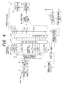
- FIG. 4 is a drawing showing the construction of the transmission apparatus in an OFDM-CDMA communication system of a second embodiment of the invention, where the same reference numbers are used for parts that are the same as those of the first embodiment shown in FIG. 2.
- This embodiment differs in that there is a power measurement unit 51 as a subcarrier propagation environment acquisition unit, and the transmission apparatus measures and acquires the propagation environment (reception power) for each subcarrier.
- the power measurement unit 51 uses the pilots that have been time multiplexed on the Uplink signal to calculate the reception power for each subcarrier, and inputs the results to the subcarrier group determination unit unit 33. After that, control is performed the same as in the first embodiment.
- the conventional method of allotting a total of M ⁇ N number of subcarrier components, which are obtained by multiplying M number of symbols by channel ization code, to M ⁇ N number of subcarriers in the order of frequency is useful in that the amount of transmitted information is decreased since it is not necessary to exchange the corresponding relation between the subcarrier components S 1 to S MN and subcarriers f 1 to f MN between the base station and the mobile station. Therefore, when the communication environment is good, M ⁇ N number of subcarrier components are allotted to each subcarrier in order of frequency, and when the communication environment is not good, M ⁇ N number of subcarrier components are allotted to subcarriers based on the group divisions of the first embodiment.
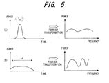
- Fluctuation in the frequency selective fading is intimately related to multipaths.
- the power is obtained as a function of time, however, as shown on the right side of the figure, after Fourier transformation, the frequency selective fading is obtained.
- the frequency selective fading becomes gradual.
- the communication environment is not good and the multipath delay spread T D is large, fluctuation of the frequency selective fading becomes large.
- FIG. 6 is a drawing showing the construction of the transmission apparatus in an OFDM-CDMA communication system of this third embodiment of the invention, where the same reference numbers are used for parts that are the same as those of the first embodiment shown in FIG. 2.
- This embodiment differs in that there is a communication environment acquisition unit 52 and group determination control unit 53.
- the communication environment acquisition unit 52 demodulates a signal from the mobile station and acquires communication environment information, for example, delay spread, then inputs the result to the group determination control unit 53.
- the group determination control unit 53 determines whether or not the communication environment is good based on the size of delay spread, and when the delay spread is shorter than a set value and the communication environment is good, instructs the subcarrier group determination unit 33 to allot subcarrier components S 1 to S MN to subcarriers f 1 to f MN in order of frequency.
- the group determination control unit 53 instructs the subcarrier group determination unit 33 to allot subcarrier components to subcarriers based on group divisions as in the first embodiment.
- the subcarrier group determination unit 33 notifies the rearrangement unit 46 and control signal creation unit 34 of that, and the rearrangement unit 46 allots the subcarrier components S 1 to S MN to subcarriers f 1 to f MN in the order of frequency.
- control signal creation unit 34 creates a control signal to notify the mobile station that the corresponding relation between the subcarrier components and subcarriers is the order of frequency, then spreads that control signal using spreading code for control, and inputs the result to the code multiplexing unit 45.
- the subcarrier group determination unit 33 divides the subcarriers in order of highest reception power into a first to Mth group having N number of subcarriers in each group, and allots M number of subcarrier components S 1 to S MN to each group.
- the subcarrier group determination unit 33 inputs the corresponding relation between the subcarrier components and subcarriers to the rearrangement unit 46 and control signal creation unit 34.
- the control signal creation unit 34 creates a control signal for notifying the mobile station of the corresponding relation information, then spreads that control signal using spreading code for control and inputs the result to the code multiplexing unit 45.
- the rearrangement unit uses the corresponding relation between the subcarriers S 1 to S MN and subcarriers f 1 to f MN that was input from the subcarrier group determination unit 33, and rearranges the subcarrier components S 1 to S MN so that they can be input to the terminals of the IFFT unit 47 according to the corresponding subcarriers.
- the FFT unit 64 performs FFT processing of the OFDM symbol data, converts to the number of subcarriers M ⁇ N number of signals S' 1 to S' MN , and outputs channel estimation values C 1 to C MN .
- Each of the multiplication units of the channel compensation unit 66 multiply the subcarrier signal of the transmission symbol by a channel compensation value to compensate for fading.
- the IFFT operation unit 81a of the delay spread estimation unit 81 performs the IFFT operation on the M ⁇ N number of channel estimation values C 1 to C MN that are output from the channel estimation unit 65, and as shown in FIG.
- the delay spreading detection unit 81b detects and outputs the delay time M as the delay spread and transmits it to the transmitting unit.
- the delay spread indicates the width of the multipaths and can be used when determining whether or not the reception state of the mobile station is good. When the delay spread is large, the maximum delay time is large and the reception state is poor, and when the delay spread is small, the maximum delay time is small and the reception state is good.
- the delay spread is measured by the reception apparatus (mobile station) and transmitted to the transmission apparatus (base station), however, it is possible to measure the delay spread for each mobile station on the base station side.
- the transmission apparatus it is also possible for the transmission apparatus to have a delay spread estimation unit as shown in FIG. 7.
- the amount of deterioration that occurs when subcarrier components S 1 to S MN are allotted to subcarriers f 1 to f MN in order of frequency becomes larger as the spreading factor increases.
- the spreading factor is 2
- only adjacent subcarriers are used, so the difference in amplitude is not that large.
- the spreading factor is 8
- a maximum of 8 subcarriers are used, so the difference in amplitude becomes large, the loss of orthogonality becomes large and deterioration of the reception characteristic becomes large.
- FIG. 9 is a drawing showing the construction of the transmission apparatus in an OFDM-CDMA communication system of a fourth embodiment of the invention, where the same reference numbers are used for parts that are the same as those of the first embodiment shown in FIG. 2.
- This embodiment differs in that there is a group determination control unit 85 that specifies the subcarrier group determination method based on the size of the spreading factor.
- the group determination control unit 85 compares the spreading factor N with a set value, and when the spreading factor N is less than the set value, instructs the subcarrier group determination unit 33 to allot subcarrier components S 1 to S MN to subcarriers f 1 to f MN in order of frequency.
- the group determination control unit 85 instructs the subcarrier group determination unit 33 to allot subcarrier components to subcarriers based on group division in the same way as done in the first embodiment.
- the subcarrier group determination unit 33 is instructed to allot subcarrier components to each subcarrier in order of frequency, it notifies the rearrangement unit 46 and control signal creation unit 34 of that, and the rearrangement unit 46 allots the subcarrier components S 1 to S MN to the subcarriers f 1 to f MN in order of frequency.
- the control signal creation unit 34 creates a control signal for notifying the mobile station that the corresponding relation between the subcarrier components and subcarriers is the order of frequency, spreads that control signal using spreading code for control, and inputs the result to the code multiplexing unit 45.
- the subcarrier group determination unit 33 when the subcarrier group determination unit 33 is instructed to allot subcarrier components to subcarriers based on the group divisions of the first embodiment, it divides the subcarrier components in order of highest reception power into a first to Mth group so there are N number of subcarriers in each group, and allots in order N number of subcarrier components S 1 to S MN to each group.
- the subcarrier group determination unit 33 inputs this corresponding relation between the subcarrier components and subcarriers to the rearrangement unit 46 and control signal creation unit 34.
- the control signal creation unit 34 creates a control signal for notifying the mobile station of this corresponding relation information, spreads that control signal using spreading code for control, and inputs the result to the code multiplexing unit 45.
- the rearrangement unit 46 uses the corresponding relation between the subcarrier components S 1 to S MN and subcarriers f 1 to f MN that is input from the subcarrier group determination unit 33 to rearrange the subcarrier components S 1 to S MN according to the corresponding subcarriers so that they can be input to the terminals of the IFFT unit 47.
- the mobile station measures the propagation environment as in the first embodiment, and must send that as feedback to the base station. Therefore, a difference occurs in the time when the propagation environment is measured, and the time when the data on which that result of the measurement is reflected is actually received.
- the mobile station is moving at a fast speed, the fluctuation in fading in the time direction is large, so there is a possibility that the propagation environment will change during this time difference.
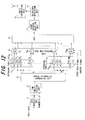
- FIG. 10 is a drawing showing the transmission apparatus in an OFDM-CDMA communication system of a fifth embodiment of the invention, where the same reference numbers are used for parts that are the same as those of the first embodiment shown in FIG. 2.
- This embodiment differs in that there is a fading frequency detection unit 91 and group determination control unit 92.
- the fading frequency detection unit 91 demodulates a signal from a mobile station and detects the fading frequency, then inputs the result to the group determination control unit 92.
- the group determination control unit 92 instructs the subcarrier group determination unit 33 to allot subcarrier components S 1 to S MN to subcarriers f 1 to f MN in order of frequency.
- the group determination control unit 92 instructs the subcarrier group determination unit 33 to allot subcarrier components to subcarriers based on group divisions as in the first embodiment.
- the subcarrier group determination unit 33 When the subcarrier group determination unit 33 is instructed to allot subcarrier components to each subcarrier in order of frequency, it notifies the rearrangement unit 46 and control signal creation unit 34 of that, and the rearrangement unit 46 allots the subcarrier components S 1 to S MN to the subcarriers f 1 to f MN in order of frequency.
- the control signal creation unit 34 creates a control signal for notifying the mobile station that the corresponding relation between the subcarrier components and subcarriers is the order of frequency, spreads that control signal using spreading code for control, and inputs the result to the code multiplexing unit 45.
- the subcarrier group determination unit 33 when instructed to allot subcarrier components to subcarriers based on the group divisions of the first embodiment, it divides the subcarrier components in order of highest reception power into a first to Mth group so there are N number of subcarriers in each group, and allots in order N number of subcarrier components S 1 to S MN to each group. Also, the subcarrier group determination unit 33 inputs this corresponding relation between the subcarrier components and subcarriers to the rearrangement unit 46 and control signal creation unit 34. The control signal creation unit 34 creates a control signal for notifying the mobile station of this corresponding relation information, spreads that control signal using spreading code for control, and inputs the result to the code multiplexing unit 45.
- the rearrangement unit 46 uses the corresponding relation between the subcarrier components S 1 to S MN and subcarriers f 1 to f MN that is input from the subcarrier group determination unit 33 to rearrange the subcarrier components S 1 to S MN according to the corresponding subcarriers so that they can be input to the terminals of the IFFT unit 47.
- FIG. 11 is a drawing showing the construction of the fading frequency estimation unit in the reception apparatus.
- the reception unit 101 selects and outputs a pilot signal from a signal received by the antenna, a sampling unit 102 samples that pilot signal over a set period, a difference calculation unit 103 calculates the difference between the levels of adjacent sampling signals, a summation unit 104 sums the difference during a specified time, and a fading frequency estimation unit 105 estimates the fading frequency based on the summation value. Taking the reception power waveform into consideration, when the fading frequency is low, the slope of the peak is gradual, and when the fading frequency is high, the slope of the peak is steep. Therefore, The fading frequency estimation apparatus shown in FIG.
- M ⁇ N number of subcarrier components which are obtained by multiplying symbol data by spreading code having a spreading factor N, are allotted to each subcarrier in the order of frequency and transmitted when the spreading factor is small, so there is no need for the transmission apparatus to notify the receiving apparatus of the corresponding relation between the subcarrier components and subcarriers, which is useful in reducing the amount of communication.
- N number of subcarrier components which are obtained by multiplication by spreading code, are allotted to each subcarrier in order of frequency and transmitted, and when frequency fading is small, N number of subcarrier components, which are obtained by multiplying symbol data having a spreading factor N, are transmitted by subcarriers having propagation environments (reception power, reception amplitude) that are close, so even when there is a time difference occurs between the time when the propagation environment is measured and the time when the data on which the result is reflected is actually received, it is possible to perform control so that no adverse effect occurs due to that time difference.
Landscapes
- Engineering & Computer Science (AREA)
- Signal Processing (AREA)
- Computer Networks & Wireless Communication (AREA)
- Quality & Reliability (AREA)
- Power Engineering (AREA)
- Mobile Radio Communication Systems (AREA)
Applications Claiming Priority (1)
| Application Number | Priority Date | Filing Date | Title |
|---|---|---|---|
| PCT/JP2005/000518 WO2006077620A1 (fr) | 2005-01-18 | 2005-01-18 | Méthode de transmission et appareil de transmission dans un système de communication ofdm-cdma |
Publications (3)
| Publication Number | Publication Date |
|---|---|
| EP1841112A1 true EP1841112A1 (fr) | 2007-10-03 |
| EP1841112A4 EP1841112A4 (fr) | 2012-07-04 |
| EP1841112B1 EP1841112B1 (fr) | 2014-06-04 |
Family
ID=36692018
Family Applications (1)
| Application Number | Title | Priority Date | Filing Date |
|---|---|---|---|
| EP20050703755 Expired - Fee Related EP1841112B1 (fr) | 2005-01-18 | 2005-01-18 | Methode de transmission et appareil de transmission dans un systeme de communication ofdm-cdma |
Country Status (5)
| Country | Link |
|---|---|
| US (1) | US8189695B2 (fr) |
| EP (1) | EP1841112B1 (fr) |
| JP (1) | JP4614977B2 (fr) |
| CN (1) | CN101099322B (fr) |
| WO (1) | WO2006077620A1 (fr) |
Cited By (3)
| Publication number | Priority date | Publication date | Assignee | Title |
|---|---|---|---|---|
| CN103312432A (zh) * | 2012-03-06 | 2013-09-18 | 华为技术有限公司 | 一种预编码方法、基站及用户设备 |
| EP2188897A4 (fr) * | 2007-08-30 | 2014-08-27 | Korea Electronics Telecomm | Appareil et procédé de modulation et de démodulation corrigeables d'erreurs de symbole faisant appel à une bande de base sélective en fréquence |
| CN103312432B (zh) * | 2012-03-06 | 2016-11-30 | 华为技术有限公司 | 一种预编码方法、基站及用户设备 |
Families Citing this family (12)
| Publication number | Priority date | Publication date | Assignee | Title |
|---|---|---|---|---|
| JP2007074224A (ja) * | 2005-09-06 | 2007-03-22 | Kddi Corp | マルチキャリア伝送システム及びマルチキャリア伝送方法 |
| KR100835175B1 (ko) * | 2006-12-07 | 2008-06-05 | 한국전자통신연구원 | 주파수 선택적 기저대역을 이용하는 디지털 통신 시스템 및그 방법 |
| CN101682384A (zh) * | 2007-05-31 | 2010-03-24 | 松下电器产业株式会社 | 无线通信移动台装置和循环延迟分集模式判定方法 |
| CN101499988B (zh) * | 2008-02-01 | 2012-03-21 | 电信科学技术研究院 | 宽带无线移动通信方法、系统和设备 |
| EP2253115B1 (fr) * | 2008-02-13 | 2013-04-03 | Telespazio S.p.A. | Procédé et système efficaces du point de vue de la bande pour émettre/recevoir un signal de communication à l'aide d'une bande de canal |
| JP5185148B2 (ja) * | 2009-01-23 | 2013-04-17 | 株式会社東芝 | 無線装置およびその方法 |
| JP4998608B2 (ja) * | 2010-09-14 | 2012-08-15 | 富士通株式会社 | 基地局及び移動局、並びにこれらを備えた通信システム |
| US9872290B2 (en) * | 2012-12-14 | 2018-01-16 | Huawei Technologies Co., Ltd. | System and method for terminal cooperation based on sparse multi-dimensional spreading |
| US9871565B2 (en) * | 2013-03-01 | 2018-01-16 | Sony Corporation | MIMO communication method, transmitting device, and receiving device |
| KR20140109761A (ko) * | 2013-03-06 | 2014-09-16 | 한국전자통신연구원 | 상향링크 제어채널 신호검출기 및 이의 시간 오차 보정방법 |
| US9225453B2 (en) * | 2013-04-09 | 2015-12-29 | Futurewei Technologies, Inc. | Optimizing optical systems using code division multiple access and/or orthogonal frequency-division multiplexing |
| JP6729059B2 (ja) * | 2016-06-24 | 2020-07-22 | 日本電気株式会社 | 中継装置、中継システム及び中継方法 |
Citations (1)
| Publication number | Priority date | Publication date | Assignee | Title |
|---|---|---|---|---|
| US20030053413A1 (en) * | 2001-08-30 | 2003-03-20 | Ntt Docomo, Inc. | Radio transmission system and method, and transmitter apparatus and receiver apparatus used in the radio transmission system |
Family Cites Families (28)
| Publication number | Priority date | Publication date | Assignee | Title |
|---|---|---|---|---|
| JP4287536B2 (ja) * | 1998-11-06 | 2009-07-01 | パナソニック株式会社 | Ofdm送受信装置及びofdm送受信方法 |
| US7039120B1 (en) * | 1998-11-30 | 2006-05-02 | Canon Kabushiki Kaisha | Device and method for the dynamic allocation of frequencies for multicarrier modulation systems |
| JP3678944B2 (ja) * | 1999-07-02 | 2005-08-03 | 松下電器産業株式会社 | 無線通信装置および無線通信方法 |
| JP3581278B2 (ja) | 1999-09-17 | 2004-10-27 | 松下電器産業株式会社 | Ofdm−cdma方式受信装置 |
| KR100416973B1 (ko) * | 1999-12-31 | 2004-02-05 | 삼성전자주식회사 | 멀티캐리어 통신시스템의 순방향 전력제어 장치 및 방법 |
| JP4313925B2 (ja) * | 2000-03-17 | 2009-08-12 | 富士通株式会社 | マルチキャリア直接拡散送受信システム,マルチキャリア直接拡散送受信機,マルチキャリア直接拡散送信機及びマルチキャリア直接拡散受信機 |
| US6721569B1 (en) * | 2000-09-29 | 2004-04-13 | Nortel Networks Limited | Dynamic sub-carrier assignment in OFDM systems |
| US6947748B2 (en) * | 2000-12-15 | 2005-09-20 | Adaptix, Inc. | OFDMA with adaptive subcarrier-cluster configuration and selective loading |
| JP4323103B2 (ja) * | 2001-02-20 | 2009-09-02 | 三菱電機株式会社 | 移動体通信システム、マルチキャリアcdma送信装置およびマルチキャリアcdma受信装置 |
| JP3607643B2 (ja) * | 2001-07-13 | 2005-01-05 | 松下電器産業株式会社 | マルチキャリア送信装置、マルチキャリア受信装置、およびマルチキャリア無線通信方法 |
| JP3628987B2 (ja) * | 2001-07-31 | 2005-03-16 | 松下電器産業株式会社 | 無線通信装置および無線通信方法 |
| JP2003069531A (ja) * | 2001-08-23 | 2003-03-07 | Mitsubishi Electric Corp | 移動体通信システム、マルチキャリアcdma送信装置およびマルチキャリアcdma受信装置 |
| WO2003021829A1 (fr) * | 2001-08-30 | 2003-03-13 | Fujitsu Limited | Systeme et procede d'emission amrc a porteuses multiples |
| JP2003101511A (ja) * | 2001-09-26 | 2003-04-04 | Yrp Mobile Telecommunications Key Tech Res Lab Co Ltd | マルチキャリアスペクトル拡散通信装置及びマルチキャリアスペクトル拡散通信システム |
| WO2003032543A1 (fr) * | 2001-09-28 | 2003-04-17 | Fujitsu Limited | Dispositif de commande de frequence automatique ofdm et procede associe |
| JP3727283B2 (ja) * | 2001-11-26 | 2005-12-14 | 松下電器産業株式会社 | 無線送信装置、無線受信装置及び無線送信方法 |
| JP4067873B2 (ja) * | 2002-05-24 | 2008-03-26 | 三菱電機株式会社 | 無線伝送装置 |
| JP4115784B2 (ja) * | 2002-09-11 | 2008-07-09 | 三菱電機株式会社 | 再送制御方法および通信装置 |
| JP3732830B2 (ja) * | 2002-10-10 | 2006-01-11 | 松下電器産業株式会社 | マルチキャリア送信装置及びマルチキャリア送信方法 |
| JP4163941B2 (ja) * | 2002-12-24 | 2008-10-08 | 松下電器産業株式会社 | 無線送信装置及び無線送信方法 |
| KR100552680B1 (ko) * | 2003-02-17 | 2006-02-20 | 삼성전자주식회사 | 다중 안테나 ofdm 통신 시스템에서의 papr 저감방법 및 이를 사용하는 다중 안테나 ofdm 통신 시스템 |
| KR100557158B1 (ko) * | 2003-11-12 | 2006-03-03 | 삼성전자주식회사 | 직교 주파수 분할 다중 방식을 사용하는 이동통신시스템에서 부반송파 할당을 위한 장치 및 방법 |
| KR100566274B1 (ko) * | 2003-11-20 | 2006-03-30 | 삼성전자주식회사 | 직교주파수분할다중 시스템에서 부반송파 할당 장치 및방법 |
| US7826435B1 (en) * | 2004-03-05 | 2010-11-02 | Zte (Usa) Inc. | Power control in OFDM and OFDMA wireless communication networks |
| KR20050089698A (ko) * | 2004-03-05 | 2005-09-08 | 삼성전자주식회사 | 어레이 안테나를 갖는 이동통신시스템에서 데이터 송/수신장치 및 방법 |
| US8270512B2 (en) * | 2004-08-12 | 2012-09-18 | Interdigital Technology Corporation | Method and apparatus for subcarrier and antenna selection in MIMO-OFDM system |
| JP3786129B2 (ja) * | 2004-08-20 | 2006-06-14 | 日本電気株式会社 | 直交周波数分割多重変復調回路 |
| US7265714B2 (en) * | 2004-09-23 | 2007-09-04 | Interdigital Technology Corporation | Pattern diversity to support a MIMO communications system and associated methods |
-
2005
- 2005-01-18 JP JP2006553774A patent/JP4614977B2/ja not_active Expired - Fee Related
- 2005-01-18 WO PCT/JP2005/000518 patent/WO2006077620A1/fr active Application Filing
- 2005-01-18 EP EP20050703755 patent/EP1841112B1/fr not_active Expired - Fee Related
- 2005-01-18 CN CN2005800465629A patent/CN101099322B/zh not_active Expired - Fee Related
-
2007
- 2007-07-05 US US11/822,354 patent/US8189695B2/en not_active Expired - Fee Related
Patent Citations (1)
| Publication number | Priority date | Publication date | Assignee | Title |
|---|---|---|---|---|
| US20030053413A1 (en) * | 2001-08-30 | 2003-03-20 | Ntt Docomo, Inc. | Radio transmission system and method, and transmitter apparatus and receiver apparatus used in the radio transmission system |
Non-Patent Citations (2)
| Title |
|---|
| NOVAK R ET AL: "EFFICIENT PACKET DATA SERVICE IN A SPREAD SPECTRUM OFDM CELLULAR SYSTEM WITH 2-DIMENSIONAL RADIO RESOURCE ALLOCATION", EUROPEAN TRANSACTIONS ON TELECOMMUNICATIONS, WILEY & SONS, CHICHESTER, GB, vol. 15, no. 3, 1 May 2004 (2004-05-01), pages 185-199, XP001199003, ISSN: 1124-318X, DOI: 10.1002/ETT.965 * |
| See also references of WO2006077620A1 * |
Cited By (4)
| Publication number | Priority date | Publication date | Assignee | Title |
|---|---|---|---|---|
| EP2188897A4 (fr) * | 2007-08-30 | 2014-08-27 | Korea Electronics Telecomm | Appareil et procédé de modulation et de démodulation corrigeables d'erreurs de symbole faisant appel à une bande de base sélective en fréquence |
| CN103312432A (zh) * | 2012-03-06 | 2013-09-18 | 华为技术有限公司 | 一种预编码方法、基站及用户设备 |
| CN103312432B (zh) * | 2012-03-06 | 2016-11-30 | 华为技术有限公司 | 一种预编码方法、基站及用户设备 |
| US9660707B2 (en) | 2012-03-06 | 2017-05-23 | Huiawei Technologies Co., Ltd. | Precoding method, base station and user equipment |
Also Published As
| Publication number | Publication date |
|---|---|
| CN101099322A (zh) | 2008-01-02 |
| JPWO2006077620A1 (ja) | 2008-06-12 |
| JP4614977B2 (ja) | 2011-01-19 |
| EP1841112A4 (fr) | 2012-07-04 |
| US20070258509A1 (en) | 2007-11-08 |
| US8189695B2 (en) | 2012-05-29 |
| EP1841112B1 (fr) | 2014-06-04 |
| CN101099322B (zh) | 2012-08-22 |
| WO2006077620A1 (fr) | 2006-07-27 |
Similar Documents
| Publication | Publication Date | Title |
|---|---|---|
| EP1841112B1 (fr) | Methode de transmission et appareil de transmission dans un systeme de communication ofdm-cdma | |
| US8385933B2 (en) | Base station device and radio communication device | |
| CN1805422B (zh) | 在正交频分复用通信系统中发射/接收前同步序列的方法 | |
| JP4569929B2 (ja) | 通信装置 | |
| US7693035B2 (en) | OFDM receiving method and OFDM receiving apparatus | |
| EP1450505B1 (fr) | Procede de transmission multiplex a division de frequences orthogonales | |
| EP2148483B1 (fr) | Système MDFO avec des rotations de phase par groupe de sous-porteuses | |
| KR100865251B1 (ko) | 파일럿 신호 전송 방법 및 장치 | |
| CA2372247C (fr) | Procede d'architecture de canaux et station de base avec celui-ci | |
| CN100559744C (zh) | 无线电发送设备 | |
| US8520748B2 (en) | Transmitter, OFDM communication system, and transmission method | |
| US20030185179A1 (en) | Radio communication apparatus and radio communication method | |
| US20050084000A1 (en) | Method and apparatus for transmission and reception within an OFDM communication system | |
| CN101099319B (zh) | 频分通信系统 | |
| JP4198428B2 (ja) | 無線伝送装置 | |
| US7616608B2 (en) | OFDM-CDMA transmission device and OFDM-CDMA transmission method | |
| JP4612511B2 (ja) | 受信装置及び受信方法 | |
| KR20050075553A (ko) | 다중반송파 코드분할다중접속 시스템에서의 역방향 파일럿설계 방법 | |
| JP4998608B2 (ja) | 基地局及び移動局、並びにこれらを備えた通信システム | |
| JP2003018121A (ja) | 無線通信装置及び無線通信方法 | |
| KR101040465B1 (ko) | Cazac 코드 기반 이동통신 시스템에서의 채널 추정방법 | |
| CN101662444A (zh) | 正交频分多路复用发送装置、方法、通信终端和基站装置 |
Legal Events
| Date | Code | Title | Description |
|---|---|---|---|
| PUAI | Public reference made under article 153(3) epc to a published international application that has entered the european phase |
Free format text: ORIGINAL CODE: 0009012 |
|
| 17P | Request for examination filed |
Effective date: 20070709 |
|
| AK | Designated contracting states |
Kind code of ref document: A1 Designated state(s): DE FR GB |
|
| DAX | Request for extension of the european patent (deleted) | ||
| RBV | Designated contracting states (corrected) |
Designated state(s): DE FR GB |
|
| A4 | Supplementary search report drawn up and despatched |
Effective date: 20120606 |
|
| RIC1 | Information provided on ipc code assigned before grant |
Ipc: H04J 11/00 20060101AFI20120531BHEP Ipc: H04L 5/00 20060101ALI20120531BHEP Ipc: H04B 1/707 20110101ALI20120531BHEP Ipc: H04L 1/00 20060101ALI20120531BHEP Ipc: H04L 25/02 20060101ALI20120531BHEP |
|
| 17Q | First examination report despatched |
Effective date: 20120903 |
|
| REG | Reference to a national code |
Ref country code: DE Ref legal event code: R079 Ref document number: 602005043782 Country of ref document: DE Free format text: PREVIOUS MAIN CLASS: H04J0011000000 Ipc: H04L0027260000 |
|
| GRAP | Despatch of communication of intention to grant a patent |
Free format text: ORIGINAL CODE: EPIDOSNIGR1 |
|
| RIC1 | Information provided on ipc code assigned before grant |
Ipc: H04L 27/26 20060101AFI20131203BHEP |
|
| INTG | Intention to grant announced |
Effective date: 20140109 |
|
| GRAS | Grant fee paid |
Free format text: ORIGINAL CODE: EPIDOSNIGR3 |
|
| GRAA | (expected) grant |
Free format text: ORIGINAL CODE: 0009210 |
|
| AK | Designated contracting states |
Kind code of ref document: B1 Designated state(s): DE FR GB |
|
| REG | Reference to a national code |
Ref country code: GB Ref legal event code: FG4D |
|
| REG | Reference to a national code |
Ref country code: DE Ref legal event code: R096 Ref document number: 602005043782 Country of ref document: DE Effective date: 20140717 |
|
| REG | Reference to a national code |
Ref country code: DE Ref legal event code: R097 Ref document number: 602005043782 Country of ref document: DE |
|
| PLBE | No opposition filed within time limit |
Free format text: ORIGINAL CODE: 0009261 |
|
| STAA | Information on the status of an ep patent application or granted ep patent |
Free format text: STATUS: NO OPPOSITION FILED WITHIN TIME LIMIT |
|
| 26N | No opposition filed |
Effective date: 20150305 |
|
| REG | Reference to a national code |
Ref country code: DE Ref legal event code: R097 Ref document number: 602005043782 Country of ref document: DE Effective date: 20150305 |
|
| REG | Reference to a national code |
Ref country code: FR Ref legal event code: PLFP Year of fee payment: 12 |
|
| PGFP | Annual fee paid to national office [announced via postgrant information from national office to epo] |
Ref country code: GB Payment date: 20151103 Year of fee payment: 12 |
|
| PGFP | Annual fee paid to national office [announced via postgrant information from national office to epo] |
Ref country code: FR Payment date: 20151208 Year of fee payment: 12 |
|
| PGFP | Annual fee paid to national office [announced via postgrant information from national office to epo] |
Ref country code: DE Payment date: 20160112 Year of fee payment: 12 |
|
| REG | Reference to a national code |
Ref country code: DE Ref legal event code: R119 Ref document number: 602005043782 Country of ref document: DE |
|
| GBPC | Gb: european patent ceased through non-payment of renewal fee |
Effective date: 20170118 |
|
| REG | Reference to a national code |
Ref country code: FR Ref legal event code: ST Effective date: 20170929 |
|
| PG25 | Lapsed in a contracting state [announced via postgrant information from national office to epo] |
Ref country code: FR Free format text: LAPSE BECAUSE OF NON-PAYMENT OF DUE FEES Effective date: 20170131 |
|
| PG25 | Lapsed in a contracting state [announced via postgrant information from national office to epo] |
Ref country code: DE Free format text: LAPSE BECAUSE OF NON-PAYMENT OF DUE FEES Effective date: 20170801 Ref country code: GB Free format text: LAPSE BECAUSE OF NON-PAYMENT OF DUE FEES Effective date: 20170118 |