EP2148483B1 - Système MDFO avec des rotations de phase par groupe de sous-porteuses - Google Patents
Système MDFO avec des rotations de phase par groupe de sous-porteuses Download PDFInfo
- Publication number
- EP2148483B1 EP2148483B1 EP09011116.2A EP09011116A EP2148483B1 EP 2148483 B1 EP2148483 B1 EP 2148483B1 EP 09011116 A EP09011116 A EP 09011116A EP 2148483 B1 EP2148483 B1 EP 2148483B1
- Authority
- EP
- European Patent Office
- Prior art keywords
- propagation path
- transmitter
- receiver
- rotation
- signals
- Prior art date
- Legal status (The legal status is an assumption and is not a legal conclusion. Google has not performed a legal analysis and makes no representation as to the accuracy of the status listed.)
- Active
Links
- 238000004891 communication Methods 0.000 claims description 21
- 238000013506 data mapping Methods 0.000 claims description 8
- 230000007480 spreading Effects 0.000 description 22
- 238000000034 method Methods 0.000 description 17
- 230000005540 biological transmission Effects 0.000 description 14
- 238000010586 diagram Methods 0.000 description 12
- 230000000694 effects Effects 0.000 description 10
- 238000000605 extraction Methods 0.000 description 6
- 238000006243 chemical reaction Methods 0.000 description 5
- 125000004122 cyclic group Chemical group 0.000 description 5
- 230000006870 function Effects 0.000 description 5
- 101100073352 Streptomyces halstedii sch1 gene Proteins 0.000 description 4
- 239000000969 carrier Substances 0.000 description 4
- 238000012545 processing Methods 0.000 description 4
- 101100073357 Streptomyces halstedii sch2 gene Proteins 0.000 description 3
- 101100276531 Streptomyces halstedii sch4 gene Proteins 0.000 description 3
- 238000003780 insertion Methods 0.000 description 3
- 230000037431 insertion Effects 0.000 description 3
- 230000008569 process Effects 0.000 description 3
- 238000004364 calculation method Methods 0.000 description 2
- 230000008859 change Effects 0.000 description 2
- 230000006866 deterioration Effects 0.000 description 2
- 238000005516 engineering process Methods 0.000 description 2
- 239000000284 extract Substances 0.000 description 2
- 230000009466 transformation Effects 0.000 description 2
- 230000003044 adaptive effect Effects 0.000 description 1
- 238000012937 correction Methods 0.000 description 1
- 230000002093 peripheral effect Effects 0.000 description 1
- 230000009467 reduction Effects 0.000 description 1
- 230000004044 response Effects 0.000 description 1
Images


Classifications
-
- H—ELECTRICITY
- H04—ELECTRIC COMMUNICATION TECHNIQUE
- H04L—TRANSMISSION OF DIGITAL INFORMATION, e.g. TELEGRAPHIC COMMUNICATION
- H04L27/00—Modulated-carrier systems
- H04L27/26—Systems using multi-frequency codes
- H04L27/2601—Multicarrier modulation systems
- H04L27/2626—Arrangements specific to the transmitter only
- H04L27/2627—Modulators
- H04L27/2634—Inverse fast Fourier transform [IFFT] or inverse discrete Fourier transform [IDFT] modulators in combination with other circuits for modulation
- H04L27/26362—Subcarrier weighting equivalent to time domain filtering, e.g. weighting per subcarrier multiplication
-
- H—ELECTRICITY
- H04—ELECTRIC COMMUNICATION TECHNIQUE
- H04B—TRANSMISSION
- H04B7/00—Radio transmission systems, i.e. using radiation field
- H04B7/02—Diversity systems; Multi-antenna system, i.e. transmission or reception using multiple antennas
- H04B7/04—Diversity systems; Multi-antenna system, i.e. transmission or reception using multiple antennas using two or more spaced independent antennas
- H04B7/06—Diversity systems; Multi-antenna system, i.e. transmission or reception using multiple antennas using two or more spaced independent antennas at the transmitting station
- H04B7/0613—Diversity systems; Multi-antenna system, i.e. transmission or reception using multiple antennas using two or more spaced independent antennas at the transmitting station using simultaneous transmission
- H04B7/0667—Diversity systems; Multi-antenna system, i.e. transmission or reception using multiple antennas using two or more spaced independent antennas at the transmitting station using simultaneous transmission of delayed versions of same signal
- H04B7/0671—Diversity systems; Multi-antenna system, i.e. transmission or reception using multiple antennas using two or more spaced independent antennas at the transmitting station using simultaneous transmission of delayed versions of same signal using different delays between antennas
-
- H—ELECTRICITY
- H04—ELECTRIC COMMUNICATION TECHNIQUE
- H04L—TRANSMISSION OF DIGITAL INFORMATION, e.g. TELEGRAPHIC COMMUNICATION
- H04L25/00—Baseband systems
- H04L25/02—Details ; arrangements for supplying electrical power along data transmission lines
- H04L25/0202—Channel estimation
- H04L25/0204—Channel estimation of multiple channels
-
- H—ELECTRICITY
- H04—ELECTRIC COMMUNICATION TECHNIQUE
- H04L—TRANSMISSION OF DIGITAL INFORMATION, e.g. TELEGRAPHIC COMMUNICATION
- H04L27/00—Modulated-carrier systems
- H04L27/26—Systems using multi-frequency codes
- H04L27/2601—Multicarrier modulation systems
- H04L27/2602—Signal structure
-
- H—ELECTRICITY
- H04—ELECTRIC COMMUNICATION TECHNIQUE
- H04L—TRANSMISSION OF DIGITAL INFORMATION, e.g. TELEGRAPHIC COMMUNICATION
- H04L27/00—Modulated-carrier systems
- H04L27/26—Systems using multi-frequency codes
- H04L27/2601—Multicarrier modulation systems
- H04L27/2647—Arrangements specific to the receiver only
-
- H—ELECTRICITY
- H04—ELECTRIC COMMUNICATION TECHNIQUE
- H04L—TRANSMISSION OF DIGITAL INFORMATION, e.g. TELEGRAPHIC COMMUNICATION
- H04L5/00—Arrangements affording multiple use of the transmission path
- H04L5/0001—Arrangements for dividing the transmission path
- H04L5/0014—Three-dimensional division
- H04L5/0016—Time-frequency-code
-
- H—ELECTRICITY
- H04—ELECTRIC COMMUNICATION TECHNIQUE
- H04L—TRANSMISSION OF DIGITAL INFORMATION, e.g. TELEGRAPHIC COMMUNICATION
- H04L5/00—Arrangements affording multiple use of the transmission path
- H04L5/0001—Arrangements for dividing the transmission path
- H04L5/0014—Three-dimensional division
- H04L5/0023—Time-frequency-space
Definitions
- the present invention relates to an orthogonal frequency division multiplexing (OFDM) system which uses a frequency band that is constituted by a plurality of subchannels.
- OFDM orthogonal frequency division multiplexing
- CDT cyclic delay transmit
- a method of obtaining a superior average BER by adopting the aforementioned CDT diversity in a method called soft combining that can obtain a site diversity effect.
- base stations which are transmitters provided with a plurality of sectors, transmits signals using the same frequency and same time from transmitting antennas that belong to each sector particularly to the same receiver that is positioned near the sector edge so that a combined wave is received by the receiver side (Non-patent document 2).
- FIG. 16 is a schematic drawing that shows the appearance of signals being transmitted from transmitting antennas 1a, 1b that are provided on transmitters belonging to two different sectors to a receiving antenna 2a that is provided on a receiver. As shown in the drawing, signals s1, s2 are respectively transmitted from the transmitting antenna 1a and the transmitting antenna 1b, and a combined wave is received by the receiving antenna 2a.
- FIG 17A shows a delay profile h1 that is time-domain representation of the propagation path between the transmitting antenna 1a ( FIG 16 ) and the receiving antenna 2a ( FIG 16).
- FIG 17B shows a delay profile h2 that is time-domain representation of the propagation path between the transmitting antenna 1b ( FIG 16 ) and the receiving antenna 2a ( FIG 16 ).
- the horizontal axis denotes time and the vertical axis denotes electrical power.
- the signals s11 and s12 in FIG 17A are signals s1 that are transmitted from the transmitting antenna 1a, and represent signals that have reached the receiving antenna 2a by passing along two different propagation paths. Also, the signals s21, s22, s23 are signals s2 that are transmitted from the transmitting antenna 1b, and represent signals that have reached the receiving antenna 2a by passing along three different propagation paths.
- the transmitting signals can be regarded as having reached the receiving antenna 2a ( FIG 16 ) by passing through a propagation path that is a combination of the delay profiles h1 and h2, as shown in FIG 18 .
- the time domain t1 of FIG 18 corresponds to the delay profile h1 ( FIG 17A )
- the time domain t2 corresponds to the delay profile h2 ( FIG. 17B ).
- Non-patent documents 3 and 4 By contrast, by multiplying an orthogonal code that is unique to each sector by a subcarrier for propagation path estimation between the respective sectors in which transmitters are placed, while transmitting the subcarriers for propagation path estimation using the same frequency and same time, the subcarriers for propagation path estimation from each sector are separated on the receiver side, and so propagation path estimation is individually performed (Non-patent documents 3 and 4).
- FIG. 19A shows the constitution of a signal s1 that is transmitted from the transmitting antenna 1a ( FIG. 16 ).
- the signal s1 is constituted from a region r1 and a region r2.
- region r1 is disposed a symbol for propagation path estimation that is a known symbol
- region r2 is disposed a common data channel that is a data symbol.
- FIG. 19B shows the constitution of a signal s2 that is transmitted from the transmitting antenna 1b ( FIG. 16 ).
- the signal s2 is constituted from a region r3 and a region r4.
- region r3 is disposed a symbol for propagation path estimation
- region r4 is disposed a common data channel.
- the symbols for propagation path estimation that are included in the regions r1 and r3 are used to obtain the propagation path information that is required for demodulating the data that is contained in the regions r2 and r4.
- FIG. 20 is a configuration drawing of the signal s3 that is transmitted from three transmitters that belong to different sectors to a receiver.
- the signal s3 is constituted from sub-carriers sc1 to sc12.
- the sub-carriers sc1 to sc4, sc5 to sc8, and sc9 to sc12 are respectively included in the frequency ranges f1, f2, f3.
- the signals s31 to s33 represent signals that are transmitted from transmitters that are disposed in sectors #1 to #3.
- Orthogonal codes C1 (1, 1, 1, 1), C2 (1, -1, 1, -1), and C3 (1, 1, -1, -1) are respectively multiplied by the signals s31 to s33.
- the signal s31 that is transmitted from the transmitter that is arranged in sector #1 is included in the addition result, but the signals s32, s32 from the transmitters respectively arranged in sectors #2 and #3 become 0. It is therefore possible to separate each signal even by performing transmission of the signals s31 to s33 using the same frequency and the same time. This situation is referred to as "the orthogonality being maintained”.
- the signal s4 is constituted from sub-carriers sc1 to sc12.
- the signals s41, s42 represent signals that are transmitted from transmitters respectively arranged in sectors #1 and #2.
- the code C4 (1, 1, 1, 1) is multiplied by the signals s41, 42.
- the soft combining method is a method of suppressing the interference component while increasing the signal component of the receiver by transmitting the same signal that is generated from the same data at the same timing from transmitters arranged in two sectors to the same receiver.
- Equation (1) the phase rotation of the following Equation (1) is multiplied by the kth subcarrier.
- the signal from the transmitting antenna 1a becomes as shown in FIG. 21 , and so enters a state in which the orthogonality with the transmitted signal from the transmitting antenna 1a ( FIG 16 ) is lost.
- N in the abovementioned Equation (1) denotes the number of points of the inverse fast Fourier transform (IFFT) during multi-carrier modulation
- T denotes the delay point difference (delay time difference) between two transmitting antennas.
- non-patent document 5 discloses a transmission method that involves transmitting with a format that retains the orthogonality between sectors adding a delay (rotation) only to the data portion even in the case of performing soft combining of signals for sector propagation path estimation. Also, it discloses that the delay amount can be informed from the base station to the transmitter.
- this technology is premised on receiving the subcarrier for propagation path estimation that has not been delay processed by the receiver, utilizing the orthogonality to estimate the propagation path from each transmitter, and, based on the delay amount that is notified from the base station, estimating the propagation path during soft combining.
- US 6,131,016 describes a system providing transmit diversity with feedback to enhance the reception of communication signals at a wireless communication terminal.
- Multiple antennae transmit multi-carrier information signals such as OFDM including pilot tones.
- the wireless communication terminal receives the pilot tones and performs processing on those tones to detect the relationship between the information signals transmitted from the various antennae of the base station.
- US 2002/0196734 A1 describes an OFDM system transceiver for transmitting frequency dividing data in parallel includes antenna elements for receiving known reception and reception data signals.
- the FFTs transform the known reception signals and the reception data signals to obtain known reception sub-carrier signals and propagation path estimating values of each of the reception data sub-carrier signals with respect to each of the known reception sub-carrier signals.
- the present invention was achieved in view of the above circumstances, and has as its object to provide a communication system, which is realized as defined in claim 1.
- the communication system of the present invention was achieved to resolve the aforementioned issues, and is a communication system comprising a receiver and a transmitter employing Orthogonal Frequency Division Multiplexing (OFDM), wherein each of a plurality of groups consists of a plurality of consecutive subcarriers modulated by data or a known signal; and wherein the transmitter comprises:
- OFDM Orthogonal Frequency Division Multiplexing
- an orthogonal frequency division multiple access (OFDMA) system shall be described assuming that the number of frequency subchannels is 12, the number of subcarriers is 768, and the number of FFT points is 1,024. Also, the frequency subchannel that realizes the path diversity differs for every frame. That is, the description is given for the cases of whether or not to perform soft combining for each frequency subchannel or the delay amount being independently determined for each frequency subchannel, but is not limited thereto.
- FIG 1A is a schematic diagram of the case of transmitters communicating with receivers.
- the receivers 4a to 4c perform communication with the transmitter 3a.
- the receivers 4b to 4e perform communication with the transmitter 3b. That is, the receivers 4b and 4c combine and receive the same signals from both transmitters 3a and 3b by soft combining.
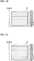
- FIG 1B and FIG 1C are drawings that show the constitution of the signals s5 and s6 that are transmitted from the transmitters 3a and 3b.
- the vertical axis represents frequency while the horizontal axis represents time.
- the drawings show the case of the signals s5 and s6 each being constituted from 12 subchannels sch1 to sch12.
- a signal is transmitted from the transmitter 3a to the receiver 4c using the subchannels sch2 to sch4. Also, a signal is transmitted from the transmitter 3a to the receiver 4a using the subchannels sch5 to sch12.
- a signal is transmitted from the transmitter 3b to the receiver 4b using the subchannel sch1. Also, a signal is transmitted from the transmitter 3b to the receiver 4c using the subchannels sch2 to sch4. Also, a signal is transmitted from the transmitter 3b to the receiver 4d using the subchannels sch5 to sch10. Also, a signal is transmitted from the transmitter 3b to the receiver 4e using the subchannels sch11 and sch12.
- the same signal is transmitted from the transmitters 3a and 3b to the receiver 4b. Also, in the subchannels sch2 to sch4, the same signal is transmitted from the transmitters 3a and 3b to the receiver 4c.
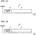
- FIG 2A is a drawing that shows the constitution of an OFDM signal s7 that is transmitted from the transmitter 3a ( FIG 1A ). Also, FIG. 2A is a drawing that shows the constitution of an OFDM signal s8 that is transmitted from the transmitter 3b ( FIG 1A ). In these drawings, the vertical axis represents frequency while the horizontal axis represents time.
- Regions r5, r7 that are included in the OFDM signals s7, s8 are subcarriers for propagation path estimation that are constituted by 1 OFDM symbol. Note that here a subcarrier for propagation path estimation is described in the case of being constituted by 1 OFDM symbol, but the subcarrier for propagation path estimation may be constituted by a plurality of OFDM symbols. Also, all of the subcarriers may be subcarriers for propagation path estimation, but an arrangement is also possible in which every other subcarrier is a subcarrier for propagation path estimation.
- regions r6, r8 that are included in the OFDM signals s7, s8 are OFDM symbols that transmit data, and are normally constituted by a plurality of OFDM symbols.
- orthogonal codes C5, C6 that are codes which are respectively orthogonal are allocated to each subcarrier.
- FIG 3 is a diagram that shows the relationship between the allocated orthogonal codes and the subcarriers.
- the orthogonal code C5 (1, 1, 1, 1) is repeatedly allocated to 768 subcarriers. That is, one orthogonal code is repeatedly allocated to the subcarriers.
- the number of subcarriers in each group to multiply the orthogonal code is 4. Note that the number of subcarriers per group in one or a plurality of subchannels may be made the same.
- the orthogonal code C6 (1, 1, -1, -1) is repeatedly allocated to 768 subcarriers.
- C5 ⁇ C6* * indicates the complex conjugate
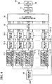
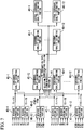
- FIG. 4 is a block diagram that shows the constitution of the transmitter according to the first embodiment of the present invention.
- This transmitter has a scheduling portion 10, propagation path estimation symbol generating portions 11-1 to 11-12, data mapping portions 12-1 to 12-12, multiplex portions 13-1 to 13-12, rotation portions 14-1 to 14-12, IFFT portion 15, GI (guard interval) insertion ⁇ P/S (parallel/serial) conversion portion 16, D/A (digital/analog) converter 17, RF (radio frequency) portion 18, and transmitting antenna 19.
- GI guard interval
- P/S parallel/serial
- D/A digital/analog converter
- RF radio frequency
- the scheduling portion 10 sorts data that is input to the transmitter to each subchannel. Here, the case of 12 subchannels shall be described. Also, the scheduling portion 10 outputs control signals to the rotation portions 14-1 to 14-12.
- the propagation path estimation symbol generating portions 11-1 to 11-12 generate symbols for propagation path estimation of each subchannel.
- the data mapping portions 12-1 to 12-12 perform error correction in the data to be transmitted, and perform modulation in every allocated subcarrier.
- a code allocation portion (not illustrated) of the propagation path estimation symbol generating portions 11-1 to 11-12 allocates code of a code length that is orthogonal with another transmitter to every subcarrier.
- the multiplex portions 13-1 to 13-12 select any of the symbols for propagation path estimation that are input data symbols or known symbols.
- the rotation portions 14-1 to 14-12 apply rotation to each subcarrier base on the control signal that is output from the scheduling portion 10.
- the IFFT portion 15 converts the signal of the frequency domain to a signal of the time domain by performing an inverted fast Fourier transformation on the signals that are output from the rotation portions 14-1 to 14-12.
- the number of points of the inverted fast Fourier transformation is 1024.
- the GI insertion ⁇ P/S conversion portion 16 inserts guard intervals for attempting a reduction in inter-symbol interference. Also, it converts parallel signals to serial signals.
- the D/A converter 17 converts digital signals to analog signals.
- the RF portion 18 converts analog signals until a frequency band to be transmitted, and performs waveform reshaping.
- the transmitting antenna 19 transmits radio waves to a receiver.
- FIG. 5 is a configuration diagram of the rotation portion 14-1 ( FIG. 4 ) according to the first embodiment of the present invention.
- This rotation portion 14-1 has a rotation amount determining portion 20, and complex multiplier portions 21-1 to 21-64.
- the rotation amount determining portion 20 determines rotation amounts W1 to W16 for every four subcarriers (each W1 to W16 is a real number or a complex number, and the amplitude thereof is "1") based on a control signal that is output from a scheduling portion 10 ( FIG. 4 ).
- the rotation amount determining portion 20 may perform control so that the phase rotation amount difference between adjacent groups is the same. Also, it may make the phase rotation amount difference between adjacent groups within one or a plurality of subchannels the same. Also, one of the groups within a subchannel in which the phase rotation amount difference is set to be the same may be made a reference group, and the absolute value of the phase rotation amount of that group may be determined based on the propagation path state of the receiver. Also, the rotation amount determining portion 20 may provide a unique phase rotation amount difference to each transmitter, and may provide a phase rotation to the subcarriers of all the OFDM symbols using the rotation amount.
- the complex multiplier portions 21-1 to 21-64 multiply input signals fk1 to fk64 and the rotation amounts W1 to W16.
- there are input signals (fk1 to fk64) because 768 subcarriers are used as 12 subchannels, and so the number of subcarriers used per subchannel is 64.
- the reason for determining the rotation amount (W1 to W16) for every 4 subcarriers is that it is possible to maintain the orthogonal relationship by making them identical among the four subcarriers. This is because the subcarriers for propagation path estimation are in an orthogonal relationship with the four subcarriers.
- the signals that are transmitted to the receivers 4b and 4c are transmitted from the transmitter 3b as well, so a rotation is provided to the signal that is transmitted from the transmitter 3a.
- a description will be given for the case of the rotation amount of the signal that is transmitted to the receiver 4b being 1, and rotation amount of the signal that is transmitted to the receiver 4c being 2.
- the data that is to be transmitted to the receiver 4b is output to the data mapping portion 12-1
- the data that is to be transmitted to the receiver 4c is output the data mapping portions 12-2 to 12-4
- the data that is to be transmitted to the receiver 4a is output from the data mapping portions 12-5 to 12-12 by the scheduling portion 10 ( FIG. 4 ).
- the symbol for propagation path estimation Prior to the transmission of data, based on the constitution of the signal of FIG. 2A and FIG. 2B , the symbol for propagation path estimation is selected by the multiplex portions 13-1 to 13-12, and output to the rotation portions 14-1 to 14-12.
- the symbols for propagation path estimation that are generated by the propagation path estimation symbol generating portions 11-1 to 11-12 are those in which the orthogonal code C5 is repeated 16 times. The identical orthogonal code C5 is therefore used for all of the propagation path estimation symbol generating portions 11-1 to 11-12.
- a control signal is output from the scheduling portion 10 to the rotation portions 14-1 to 14-12, 1 is input as the rotation amount to the rotation portion 14-1,2 is input as the rotation amount from the rotation portion 14-2 to the rotation portion 14-4, and 0 is input as the rotation amount from the rotation portion 14-5 to the rotation portion 14-12.
- the rotation amounts W1 to W16 are determined.
- the difference between the rotation amounts W1 and W2 is four subcarriers, and so by multiplying by 4, it is determined to be 2 ⁇ ⁇ ⁇ m ⁇ 4/1024.
- the phase difference between Wk and Wk + 1 (k is an integer from 1 to 15) in the rotation portion 14-1 is 2 ⁇ ⁇ ⁇ 4/1024
- the phase difference between Wk and Wk + 1 in the rotation portions 14-2 to 14-4 is 2 ⁇ ⁇ ⁇ 2 ⁇ 4/1024
- the phase difference between Wk and Wk + 1 in the rotation portions 14-5 to 14-12 is 0.
- the absolute phase of the rotation amount W1 of each rotation portion is not particularly limited.
- the rotation amounts of adjacent subchannels are made the same. That is, the absolute phase difference of the rotation amount W16 of the rotation portion 14-2 and the rotation amount W1 of the rotation portion 14-3 is preferably 2 ⁇ ⁇ ⁇ 2 ⁇ 4/ (1024).
- the absolute phase of the rotation amount W1 can be determined with reference to the data that is to be transmitted from the receiver.
- the identical rotation amount as during transmission of the subcarriers for propagation path estimation is provided to all of the subcarriers.
- FIG. 5 shows multipliers for providing the phase rotation in the respective subcarriers that provide the same rotation, but this is in order to simplify the description. It is possible to decrease the circuit scale by performing the process serially with one multiplier.
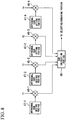
- FIG. 6 is a block diagram that shows the constitution of a receiver of the first example of the present invention.
- This receiver has a receiving antenna 30, an RF portion 31, an analog/digital (A/D) converter 32, a symbol synchronizing portion 33, a fast Fourier transform (FFT) portion 34, a propagation path estimation symbol extraction portion 35, a propagation path compensating portion 36, a propagation path estimating portion 37, a subchannel extraction portion 38, and demodulating portions 39-1 to 39-12.
- A/D analog/digital
- FFT fast Fourier transform
- the receiving antenna 30 receives signals that are transmitted from the transmitter.
- the RF portion 31 reshapes signals that the receiving antenna 30 has received and lowers the frequency until the frequency band that can be subject to A/D conversion.
- the A/D converter 32 converts analog signals to digital signals.
- the symbol synchronizing portion 33 performs synchronization to the OFDM signal.
- the FFT portion 34 performs a fast Fourier transform on the received OFDM symbol.
- the propagation path estimation symbol extraction portion 35 separates the frequency converted OFDM signal from the propagation path estimation symbol and the data symbol, outputs the propagation path estimation symbol to the propagation path estimating portion 37, and outputs the data symbol to the propagation path compensating portion 36.
- the propagation path compensating portion 36 compensates the data propagation path based on propagation path estimation information.
- the propagation path estimating portion 37 estimates the propagation path information from the propagation path estimation symbol, and estimates the quality of every transmitting antenna.
- the subchannel extraction portion 38 extracts the signals that the receiver demodulates based on the subchannel in use of information from a control portion not illustrated.
- the demodulating portions 39-1 to 39-12 perform demodulation in subchannel units based on the number of subchannels used.
- This receiver has a constitution that once demodulates all bands that are used by the OFDMA, and subsequently extracts only the subchannels that are required, but is not necessarily limited to this constitution.
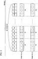
- FIG. 7 is a lineblock diagram of the propagation path estimating portion 37 ( FIG. 6 ) according to the first example of the present invention.
- the propagation path estimating portion 37 has reverse spreading portions 40-1 to 40-12, 41-1 to 41-12, subchannel quality estimating portions 42-1 to 42-12, 43-1 to 43-12, a selecting/combining portion 44, subchannel quality estimating portions 45-1 to 45-12, and virtual subchannel quality estimating portions 46-1 to 46-12.
- the reverse spreading portions are provided in two pair (reverse spreading portions 40-1 to 40-12, and reverse spreading portions 41-1 to 41-12) because signals are transmitted from the two transmitters 3a and 3b ( FIG. 1A ).
- the reverse spreading portions 40-1 to 40-12 estimate the propagation paths of signals that are transmitted from the transmitter 3a ( FIG. 1A ).
- the reverse spreading portions 41-1 to 41-12 estimate the propagation paths of signals that are transmitted from the transmitter 3b ( FIG. 1A ).
- the complex signals that are obtained by the reverse spreading portions 40-1 to 40-12, 41-1 to 41-12 are input to the selecting/combining portion 44.
- the selecting/combining portion 44 selects the reverse spreading result on the transmitting side in the case that the communication currently performed is in use of only one transmitter (the receivers 4a, 4d, 4e in FIG. 1A ). If the receiver 4a is in use, it selects the output of the reverse spreading portions 40-1 to 40-12. If the receivers 4d, 4e are in use, it selects the output of the reverse spreading portions 41-1 to 41-12.
- the selecting/combining portion 44 performs combining of the signals that are received. This is achieved by vector addition of the outputs of the reverse spreading portions 40-1 to 40-12 and the reverse spreading portions 41-1 to 41-12.
- the subchannel quality estimating portions 42-1 to 42-12 estimate the quality of the signals that are transmitted from the respective transmitters 3a, 3b based on the output of the reverse spreading portions 40-1 to 40-12. Also, the subchannel quality estimating portions 43-1 to 43-12 estimate the quality of the signals that are transmitted from the respective transmitters 3a, 3b based on the output of the reverse spreading portions 41-1 to 41-12. In the case of the present example, the propagation path estimation result of the 64 subcarriers used by each subchannel are input to the subchannel quality estimating portions 42-1 to 42-12, 43-1 to 43-12.
- the subchannel quality estimating portions 45-1 to 45-12 perform quality estimation after the combination of the signals transmitted from the transmitters 3a, 3b ( FIG 1A ) based on the output of the selecting/combining portion 44.
- the virtual subchannel quality estimating portions 46-1 to 46-12 provide either rotation to the propagation path information in the case of having received the subcarriers for propagation path estimation in which rotation has not been added at the transmitter side, and estimates the quality of the subchannel in the case of the rotation being performed. Thereby, it is possible to request the optimum subchannel from the receiver.
- the simplest method of propagation path estimation methods is a method of multiplying a complex conjugate signal of a code for each subcarrier of the subcarriers for propagation path estimation used on the transmitter side with respect to the signals in which the received subcarriers for propagation path estimation are frequency converted.
- orthogonal codes are here used between the transmitting antennas that differ between the subcarriers for propagation path estimation, the description is given for the method of propagation path estimation by reverse spreading.
- FIG. 8 is a lineblock diagram of the reverse spreading portion 40-1 ( FIG. 7 ) according to the first example of the present invention.
- the reverse spreading portion 40-1 has orthogonal code setting portions 47-1 to 47-4, complex multipliers 48-1 to 48-4, and a sum calculation portion 49.
- (1, 1, 1, 1) which is the complex conjugate of the orthogonal code C1 is set in the orthogonal code setting portion 47-1.
- (1, 1, -1, -1) which is the complex conjugate of the orthogonal code C2 is set in the orthogonal code setting portion 47-2.
- these orthogonal codes are complex multiplied by the input signals f1 to f4, and by adding and dividing by 4 in the sum calculation portion 49, it is possible to obtain the propagation path in this frequency band.
- the aforementioned first embodiment discloses the transmitter that uses the OFDMA system which utilizes a frequency band that is constituted by a plurality of subchannels.
- the transmitter allocates, to each of n subcarriers (where n is an integer of 1 or more), code Ck of code length Mk that is orthogonal with another transmitter by a code allocating portion of propagation path estimation symbol generating portions 11-1 to 11-12.
- the transmitter performs grouping n ⁇ Mk subcarriers by complex multiplier portions 21-1 to 21-64 (phase rotating portions), gives the same phase rotation to every group, determines the phase rotation amount in subchannel units by the rotation amount determining portion 20, and determines the existence of phase rotation in subchannel units by the scheduling portion 10.
- the transmitter may also be a transmitter that uses the OFDM system, with the transmitter allocating, to each of n subcarriers (where n is an integer of 1 or more), code Ck of code length Mk that is orthogonal with another transmitter by a code allocating portion of propagation path estimation symbol generating portions 11-1 to 11-12, grouping n ⁇ Mk subcarriers by complex multiplier portions 21-1 to 21-64 (phase rotating portions).
- the transmitter may provide the same phase rotation to every group, determine the phase rotation amount by the rotation amount determining portion 20, and determine the existence of phase rotation in subchannel units by the scheduling portion 10.
- subcarriers of another number may be set as 1 group without making n ⁇ Mk subcarriers 1 group.
- FIG. 9 is a diagram that shows the constitution of a subcarrier for propagation path estimation in the second example of the present invention.
- the subcarrier for propagation path estimation which is a subcarrier in which symbols for propagation path estimation are arranged, is allocated at every other subcarrier.
- a subcarrier in which a subcarrier for propagation path estimation is not allocated is used for communication of control signals (SA1 to SA384, SB1 to SB384).
- specific known symbols P1 to P384 are used for the symbols for propagation path estimation, and orthogonal codes (1, 1, 1, 1), (1, 1, -1, -1) are respectively multiplied by the known symbols in the transmitters 3a, 3b.
- FIG. 10 is a block diagram that shows the transmitter according to the second embodiment of the present invention. Portions that have the same constitution as the transmitter ( FIG. 4 ) shown in the first embodiment are denoted by the same reference numerals, and descriptions thereof shall therefore be omitted.
- the transmitter of the present embodiment differs from the transmitter according to the first embodiment on the point of having a control signal generating portion 50.
- the control signal generating portion 50 is provided because the constitution of the subcarrier for propagation path estimation was altered. Also, the propagation path estimation symbol generating portion was described in the first embodiment as generating symbols for every subchannel. However, in the present embodiment, because the case of not providing rotation in subchannel units is indicated, the propagation path estimation symbol generating portions 11-1 to 11-12 ( FIG. 4 ) are constituted by a single propagation path estimation symbol generating portion 111. Similarly, the multiplex portions 13-1 to 13-12 ( FIG. 4 ) are constituted by a single multiplex portion 131. Also, the rotation portions 14-1 to 14-12 ( FIG. 4 ) are constituted by a single rotation portion 141.
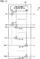
- FIG. 11 is a configuration diagram of the rotation portion 141 ( FIG. 10 ) according to the second embodiment of the present invention.
- the rotation portion 141 has a rotation amount determining portion 201, and complex multiplier portions 211-1 to 211-8, 211-9 to 211-16 to 211-761 to 211-768.
- the rotation amount determining portion 201 determines rotation amounts W1 to W96 (W1 to W96 being a real number of 1 or a complex number) for every eight subcarriers based on a rotation amount that is defined by the OFDM communication system.
- the complex multiplier portions 211-1 to 211-768 multiply input signals fk1 to fly768 and the rotation amounts W1 to W96. For example, assuming that the difference of each phase rotation amount W1 to W96 in the rotation portion 141 of the receiver shown in FIG. 11 is 0, and the difference of the phase rotation amount of the transmitter 3b ( FIG. 1A ) is 2 ⁇ ⁇ ⁇ 1 ⁇ 8/1024, when the same signal is transmitted by the same subchannel of each transmitter 3a, 3b, it is possible to receive a combined signal by the receiver.
- the orthogonality of the subcarrier for propagation path estimation is maintained similarly to the first embodiment, in addition to being capable of performing quality estimation or each subchannel of the transmitter, it is also possible to perform quality estimation after combining. That is, it is not necessary to provide the virtual subchannel quality estimating portions 46-1 to 46-12 ( FIG. 7 ) described in the receiver according to the first embodiment. It is therefore possible to simply estimate the quality of each transmitter before combining and the quality after combining.
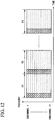
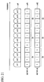
- FIG. 12 shows the horizontal axis denotes time and the vertical axis denotes frequency.
- a constitution of 1 frame is the same as the constitution of the frame already described ( FIG. 2A, FIG 2B ), and is constituted at the front by the subcarrier for propagation path estimation that is a known symbol, followed by a plurality of data symbols.
- FIG. 12 shows the case of constituting one super frame with nine frames F1 to F9.
- the receiver by selecting a suitable frame from these frames and a subchannel, it is possible to realize a high-performance OFDM communication system.
- the receiver that is used in the second embodiment can use nearly the same constitution as the receiver used in the first embodiment ( FIG. 6 ).
- the point of difference is the code that is set to the reverse spreading being one that multiplies a complex conjugate of Pk (where k is an integer from 1 to 768) by C1 or C2.
- the orthogonal code used in the transmitter 3a ( FIG. 1A ) is C11
- the orthogonal code that is used in the transmitter 3b ( FIG. 1A ) is C12.
- the rotation amount becomes half the previously indicated value.
- FIG. 13 is a block diagram that shows the constitution of the transmitter according to the third embodiment of the present invention. Portions that have the same constitution as the transmitter ( FIG. 10 ) shown in the second embodiment are denoted by the same reference numerals, and descriptions thereof will therefore be omitted.
- the transmitter of the present embodiment differs from the transmitter ( FIG. 10 ) according to the second embodiment on the point of having a time rotation portion 60.
- the time rotation portion 60 rotates the signal that is output from the IFFT portion 15. Also, the scheduling portion 10 controls whether or not the rotation portion 141 and the time rotation portion 60 are driven. In the super frame that is constituted by nine frames, the operation is the same as that of the second embodiment until the eighth frame and until the subcarrier for propagation path estimation of the ninth frame. Then in the data portion of the ninth frame, the driving of the rotation portion 141 is stopped and the time rotation portion 60 is driven.
- FIG. 14A is the propagation path of the transmitter 3a ( FIG. 1A )
- FIG. 14B is the propagation path of the transmitter 3b ( FIG. 1A ).
- the receiver that receives this frame does not have a constitution of reverse spreading, and performs conventional demodulation of a type that multiplies a complex conjugate of a subcarrier for propagation path estimation. This is because, since the propagation path estimation symbol is basically generated from the same code, all of the data symbols including the propagation path estimation symbol become the same data.
- FIG. 15 is a block diagram that shows the constitution of the receiver according to the third example of the present invention. Portions that have the same constitution as the receiver ( FIG. 6 ) of the first example are denoted by the same reference numerals, and descriptions thereof will therefore be omitted.
- the receiver of the present invention differs from the receiver according to the first example on the point of having a propagation path estimating portion 70.
- the propagation path estimating portion 70 finds a propagation path by multiplying data of the reception frequency of the subcarrier for propagation path estimation by the complex conjugate of the code that was used for generating the propagation path estimation symbols. Also, since it is not necessary to measure the power of each subchannel in the frame for frequency diversity, this frame only measures the propagation path and demodulates the data.
- the receiver may have a quality estimating portion (not illustrated) that estimates the quality of radio waves at each antenna besides the propagation path estimating portion 37 that estimates with respect to a plurality of antennas a propagation path that is the frequency response with a transmitting antenna in known symbol units that maintain the orthogonality on transmitter side.
- the receiver may also have and a quality calculating portion (not illustrated) that calculates the quality of combined propagation paths in the case of providing a predetermined phase rotation to the subcarrier of the OFDM symbol that is transmitted from each antenna from the radio wave quality of each antenna.
- the first through third embodiments disclose transmitters that use the OFDMA system which utilizes a frequency band that is constituted by a plurality of subchannels.
- the transmitters give the same phase rotation to each of the groups configured with a plurality of consecutive subcarriers modulated by a data symbol or a known symbol by complex multiplier portions 21-1 to 21-64, or 211-1 to 211-768 (phase rotating portions), determine the phase rotation amount in subchannel units by the rotation amount determining portion 20 or the rotation amount determining portion 201, and determine the existence of phase rotation in subchannel units by the scheduling portion 10.
- the transmitter that uses the OFDM system may give the same phase rotation amount to each of the groups configured by a plurality of consecutive subcarriers modulated by a data symbol or a known symbol by complex multiplier portions 211-1 to 211-768 (phase rotating portions), determine the phase rotation amount by the rotation amount determining portion 20 or the rotation amount determining portion 201, and determine the existence of phase rotation in subchannel units by the scheduling portion 10.
- control of the transmitter and receiver may be performed by recording on a computer-readable recording medium a program for realizing the functions of the scheduling portion 10, the propagation path estimation symbol generating portions 11-1 to 11-12, 111, the data mapping portions 12-1 to 12-12, the multiplex portions 13-1 to 13-12, 131, The rotation portions 14-1 to 14-12, 141, the IFFT portion 15, the GT insertion ⁇ P/S conversion portion 16, the D/A converter 17, the RF portion 18, the control signal generating portion 50, the time rotation portion 60 of FIG. 4 , FIG. 10 , and FIG.
- a "computer-readable recording medium” refers to a portable medium such as a flexible disk, magneto-optical disk, ROM, CD-ROM and the like, and a storage device such as a hard disk that is housed in a computer system.
- the "computer readable storage medium” also includes one for holding the program for a certain time, such as a volatile memory in a computer system which functions as a server or client for receiving the program sent via a network (e.g., the Internet) or a communication line (e.g., a telephone line).
- the program may be one for realizing a portion of the abovementioned functions, and it is also possible to realize the abovementioned functions in combination with a program that has already been stored in the computer system.
- the present invention can be applied to a receiver employing an OFDM system.
Claims (4)
- Système de communication comprenant un récepteur (4a, 4b, 4c, 4d, 4e) et un émetteur (3a, 3b) utilisant un Multiplexage par Répartition Orthogonale de la Fréquence, OFDM,
dans lequel chacun d'une pluralité de groupes consiste en une pluralité de sous-porteuses (fk1-fk4) consécutives modulées par des données ou par un signal connu ; et dans lequel l'émetteur (3a, 3b) comprend :une partie rotation (14-1) qui communique une même quantité de rotation de phase (W1) aux sous-porteuses configurées dans le même groupe ;la partie rotation (14-1) étant caractérisée en ce qu'elle produit une différence de quantité de rotation de phase entre des groupes adjacents, la différence de quantité de rotation de phase entre groupes adjacents étant unique pour l'émetteur. - Système de communication selon la revendication 1, dans lequel l'émetteur (3a, 3b) comprend en outre :une partie ordonnancement (10) et une partie mappage de données (12-1),la partie ordonnancement (10) envoyant, à la partie mappage de données (12-1), des données qui sont destinées à être transmises à un récepteur (4b).
- Système de communication selon la revendication 1 ou 2, dans lequel une sous-porteuse incluse dans l'un des groupes est modulée par le signal connu, le signal connu étant un signal permettant d'estimer un trajet de propagation.
- Système de communication selon la revendication 1 ou 2, dans lequel le nombre de sous-porteuses par groupe est le même dans un sous-canal ou dans une pluralité de sous-canaux, la pluralité de sous-canaux constituant une bande de fréquences.
Applications Claiming Priority (2)
| Application Number | Priority Date | Filing Date | Title |
|---|---|---|---|
| JP2005314429 | 2005-10-28 | ||
| EP06822524A EP1950900A4 (fr) | 2005-10-28 | 2006-10-27 | Emetteur, systeme de communication et procede d emission |
Related Parent Applications (1)
| Application Number | Title | Priority Date | Filing Date |
|---|---|---|---|
| EP06822524A Division EP1950900A4 (fr) | 2005-10-28 | 2006-10-27 | Emetteur, systeme de communication et procede d emission |
Publications (2)
| Publication Number | Publication Date |
|---|---|
| EP2148483A1 EP2148483A1 (fr) | 2010-01-27 |
| EP2148483B1 true EP2148483B1 (fr) | 2017-05-10 |
Family
ID=37967876
Family Applications (4)
| Application Number | Title | Priority Date | Filing Date |
|---|---|---|---|
| EP09011116.2A Active EP2148483B1 (fr) | 2005-10-28 | 2006-10-27 | Système MDFO avec des rotations de phase par groupe de sous-porteuses |
| EP06822524A Withdrawn EP1950900A4 (fr) | 2005-10-28 | 2006-10-27 | Emetteur, systeme de communication et procede d emission |
| EP09011115A Withdrawn EP2148482A1 (fr) | 2005-10-28 | 2006-10-27 | Transmetteur MDFO avec des rotations de phase par groupe de sous-porteuses et récepteur correspondant |
| EP09011117.0A Active EP2148484B1 (fr) | 2005-10-28 | 2006-10-27 | Transmetteur MDFO avec des rotations de phase par groupe de sous-porteuses |
Family Applications After (3)
| Application Number | Title | Priority Date | Filing Date |
|---|---|---|---|
| EP06822524A Withdrawn EP1950900A4 (fr) | 2005-10-28 | 2006-10-27 | Emetteur, systeme de communication et procede d emission |
| EP09011115A Withdrawn EP2148482A1 (fr) | 2005-10-28 | 2006-10-27 | Transmetteur MDFO avec des rotations de phase par groupe de sous-porteuses et récepteur correspondant |
| EP09011117.0A Active EP2148484B1 (fr) | 2005-10-28 | 2006-10-27 | Transmetteur MDFO avec des rotations de phase par groupe de sous-porteuses |
Country Status (5)
| Country | Link |
|---|---|
| US (4) | US8009751B2 (fr) |
| EP (4) | EP2148483B1 (fr) |
| JP (5) | JP4302761B2 (fr) |
| CN (3) | CN101346917A (fr) |
| WO (1) | WO2007049768A1 (fr) |
Families Citing this family (20)
| Publication number | Priority date | Publication date | Assignee | Title |
|---|---|---|---|---|
| CN102868511B (zh) | 2004-10-29 | 2016-08-03 | 夏普株式会社 | 通信方法和无线发射机 |
| EP1843497B1 (fr) | 2005-01-18 | 2018-06-20 | Sharp Kabushiki Kaisha | Appareil de communication sans fil et méthode de communication sans fil |
| CN101346917A (zh) * | 2005-10-28 | 2009-01-14 | 夏普株式会社 | 发射机、通信系统及发送方法 |
| EA012497B1 (ru) * | 2005-10-31 | 2009-10-30 | Шарп Кабусики Кайся | Терминал связи, базовая станция и система связи |
| KR100751098B1 (ko) * | 2006-02-16 | 2007-08-22 | 주식회사 팬택앤큐리텔 | 직교 주파수 분할 다중화 기반 통신 시스템에서의 파일럿심볼 전송 방법 및 장치, 그 수신방법 및 장치 |
| JP5025022B2 (ja) | 2006-07-20 | 2012-09-12 | シャープ株式会社 | マルチキャリア信号受信装置およびマルチキャリア信号受信方法 |
| JP4762203B2 (ja) * | 2007-06-29 | 2011-08-31 | 株式会社東芝 | Ofdm信号の送信方法、ofdm送信機及びofdm受信機 |
| JPWO2009054052A1 (ja) * | 2007-10-24 | 2011-03-03 | 富士通株式会社 | Ofdm通信装置およびofdm通信方法 |
| JPWO2009075098A1 (ja) * | 2007-12-10 | 2011-04-28 | パナソニック株式会社 | パイロット送信方法、mimo送信装置、及びmimo受信装置 |
| WO2009075104A1 (fr) * | 2007-12-11 | 2009-06-18 | Panasonic Corporation | Procede de transmission de pilotes, dispositif d'emission mimo et dispositif de reception mimo en communication avec ce dispositif d'emission |
| JPWO2009078162A1 (ja) * | 2007-12-14 | 2011-04-28 | パナソニック株式会社 | パイロット送信方法、mimo送信装置、及びmimo受信装置 |
| KR101513045B1 (ko) * | 2008-05-05 | 2015-04-17 | 엘지전자 주식회사 | 지연 호핑을 이용한 순환 지연 다이버시티 기반 전송 |
| US8238303B2 (en) * | 2008-11-26 | 2012-08-07 | Telefonaktiebolaget L M Ericsson (Publ) | Method and apparatus of allocating subcarriers in an orthogonal frequency division multiplexing system |
| KR101003173B1 (ko) | 2008-12-12 | 2010-12-22 | 한국전자통신연구원 | 무선 인체 영역 네트워크에서의 신호 수신 시스템 및 방법 |
| KR101552266B1 (ko) * | 2009-04-07 | 2015-09-11 | 삼성전자주식회사 | 수신기, 그의 간섭 제거 방법 및 그를 위한 송신기 |
| CN101945073B (zh) * | 2009-07-03 | 2013-02-27 | 中兴通讯股份有限公司 | 基于导频的时偏估计装置和方法 |
| US8290074B2 (en) * | 2010-01-21 | 2012-10-16 | Mitsubishi Electric Research Laboratories, Inc. | OFDM networks with pseudo-random phase precoding |
| KR100986189B1 (ko) * | 2010-08-23 | 2010-10-07 | 엘아이지넥스원 주식회사 | 신호 복원 장치 및 그 방법 |
| US10182449B2 (en) | 2016-05-04 | 2019-01-15 | Telefonaktiebolaget Lm Ericsson (Publ) | Scheduling node, transmitting node, receiving node and methods therein, for communication of data |
| CN107800524B (zh) * | 2016-09-02 | 2020-08-07 | 上海诺基亚贝尔股份有限公司 | 用于传输上行控制信息的方法和设备 |
Family Cites Families (29)
| Publication number | Priority date | Publication date | Assignee | Title |
|---|---|---|---|---|
| US5756494A (en) | 1992-07-24 | 1998-05-26 | Cephalon, Inc. | Protein kinase inhibitors for treatment of neurological disorders |
| US6131016A (en) * | 1997-08-27 | 2000-10-10 | At&T Corp | Method and apparatus for enhancing communication reception at a wireless communication terminal |
| JP3046960B1 (ja) * | 1999-01-22 | 2000-05-29 | 株式会社次世代デジタルテレビジョン放送システム研究所 | 直交周波数分割多重伝送方式及びその送受信装置 |
| JP2000354266A (ja) | 1999-06-11 | 2000-12-19 | Sony Corp | 無線通信端末装置 |
| JP3522619B2 (ja) * | 2000-01-05 | 2004-04-26 | 株式会社エヌ・ティ・ティ・ドコモ | マルチキャリアcdma伝送システムにおける送信機 |
| JP4496673B2 (ja) | 2001-06-07 | 2010-07-07 | 株式会社デンソー | Ofdm方式の送受信機 |
| EP1453229A4 (fr) | 2001-08-30 | 2007-07-11 | Fujitsu Ltd | Systeme et procede d'emission amrc a porteuses multiples |
| JP2003333008A (ja) | 2002-05-10 | 2003-11-21 | Sony Corp | 通信システムおよびその方法、受信装置およびその方法、通信装置およびその方法、ならびにプログラム |
| JP2004024180A (ja) | 2002-06-28 | 2004-01-29 | Hitachi Hometec Ltd | 脱臭機能付きペット用ボックス |
| US6940917B2 (en) | 2002-08-27 | 2005-09-06 | Qualcomm, Incorporated | Beam-steering and beam-forming for wideband MIMO/MISO systems |
| KR100630108B1 (ko) | 2002-10-10 | 2006-09-27 | 삼성전자주식회사 | 공간-시간 블럭부호를 사용하여 송신 안테나 다이버시티를지원하는 송수신 장치 |
| JP4331563B2 (ja) * | 2002-10-10 | 2009-09-16 | 三星電子株式会社 | 空間−時間ブロック符号を用いて送信アンテナダイバシティを支援する送受信装置 |
| JP4163018B2 (ja) | 2003-02-03 | 2008-10-08 | Kddi株式会社 | 伝送路特性推定装置および伝送路特性推定方法、無線復調装置、コンピュータプログラム |
| KR20060025197A (ko) | 2003-06-30 | 2006-03-20 | 닛본 덴끼 가부시끼가이샤 | 무선 통신 시스템 및 송신 모드 선택 방법 |
| US7030048B2 (en) | 2003-08-05 | 2006-04-18 | E. I. Du Pont De Nemours And Company | Thick film dielectric compositions for use on aluminum nitride substrates |
| US7242722B2 (en) * | 2003-10-17 | 2007-07-10 | Motorola, Inc. | Method and apparatus for transmission and reception within an OFDM communication system |
| KR100557158B1 (ko) * | 2003-11-12 | 2006-03-03 | 삼성전자주식회사 | 직교 주파수 분할 다중 방식을 사용하는 이동통신시스템에서 부반송파 할당을 위한 장치 및 방법 |
| KR100507541B1 (ko) | 2003-12-19 | 2005-08-09 | 삼성전자주식회사 | 직교주파수분할다중접속 시스템에서의 데이터 및 파일롯할당 방법 과 그를 이용한 송신 방법 및 그 장치, 수신방법과 그 장치 |
| JP4290048B2 (ja) | 2004-03-23 | 2009-07-01 | 三洋電機株式会社 | 受信方法および装置 |
| US7447268B2 (en) | 2004-03-31 | 2008-11-04 | Intel Corporation | OFDM system with per subcarrier phase rotation |
| JP4515155B2 (ja) * | 2004-05-25 | 2010-07-28 | 株式会社エヌ・ティ・ティ・ドコモ | 送信装置 |
| TWI246273B (en) | 2004-06-28 | 2005-12-21 | Ind Tech Res Inst | Method and apparatus for high-order PAPR reduction of an OFDM signal |
| US7676007B1 (en) | 2004-07-21 | 2010-03-09 | Jihoon Choi | System and method for interpolation based transmit beamforming for MIMO-OFDM with partial feedback |
| US20090060064A1 (en) | 2005-04-04 | 2009-03-05 | Nec Corporation | OFDM Communication System, Method for Generating Feedback Information Thereof, and Communication Apparatus |
| US20070004465A1 (en) * | 2005-06-29 | 2007-01-04 | Aris Papasakellariou | Pilot Channel Design for Communication Systems |
| CN101346917A (zh) | 2005-10-28 | 2009-01-14 | 夏普株式会社 | 发射机、通信系统及发送方法 |
| US8233552B2 (en) | 2005-11-07 | 2012-07-31 | Broadcom Corporation | Method and system for utilizing givens rotation expressions for asymmetric beamforming matrices in explicit feedback information |
| US20080083012A1 (en) * | 2006-06-26 | 2008-04-03 | Dachuan Yu | Program instrumentation method and apparatus for constraining the behavior of embedded script in documents |
| US8213541B2 (en) | 2006-09-12 | 2012-07-03 | Hera Wireless S.A. | Receiving method for receiving signals by a plurality of antennas, and a receiving apparatus and a radio apparatus using the same |
-
2006
- 2006-10-27 CN CNA2006800490199A patent/CN101346917A/zh active Pending
- 2006-10-27 WO PCT/JP2006/321563 patent/WO2007049768A1/fr active Application Filing
- 2006-10-27 EP EP09011116.2A patent/EP2148483B1/fr active Active
- 2006-10-27 JP JP2007542706A patent/JP4302761B2/ja not_active Expired - Fee Related
- 2006-10-27 EP EP06822524A patent/EP1950900A4/fr not_active Withdrawn
- 2006-10-27 CN CN200910171397XA patent/CN101667988B/zh active Active
- 2006-10-27 US US12/091,430 patent/US8009751B2/en not_active Expired - Fee Related
- 2006-10-27 CN CN200910171396A patent/CN101707581A/zh active Pending
- 2006-10-27 EP EP09011115A patent/EP2148482A1/fr not_active Withdrawn
- 2006-10-27 EP EP09011117.0A patent/EP2148484B1/fr active Active
-
2009
- 2009-03-06 JP JP2009053986A patent/JP4347410B2/ja not_active Expired - Fee Related
- 2009-03-06 JP JP2009053979A patent/JP4382144B2/ja not_active Expired - Fee Related
- 2009-06-15 JP JP2009142571A patent/JP4384710B2/ja active Active
- 2009-06-15 JP JP2009142572A patent/JP4842349B2/ja not_active Expired - Fee Related
- 2009-08-31 US US12/551,385 patent/US8014458B2/en not_active Expired - Fee Related
- 2009-08-31 US US12/551,368 patent/US8170145B2/en active Active
- 2009-08-31 US US12/551,351 patent/US8155221B2/en not_active Expired - Fee Related
Non-Patent Citations (1)
| Title |
|---|
| VISWANATH P ET AL: "Opportunistic Beamforming Using Dumb Antennas", IEEE TRANSACTIONS ON INFORMATION THEORY, IEEE PRESS, USA, vol. 48, no. 6, 1 June 2002 (2002-06-01), pages 1277 - 1294, XP002314708, ISSN: 0018-9448, DOI: 10.1109/TIT.2002.1003822 * |
Also Published As
| Publication number | Publication date |
|---|---|
| CN101667988B (zh) | 2013-08-07 |
| JP4347410B2 (ja) | 2009-10-21 |
| JP4382144B2 (ja) | 2009-12-09 |
| EP1950900A1 (fr) | 2008-07-30 |
| EP2148482A1 (fr) | 2010-01-27 |
| US8170145B2 (en) | 2012-05-01 |
| US20090316818A1 (en) | 2009-12-24 |
| EP2148483A1 (fr) | 2010-01-27 |
| JP4842349B2 (ja) | 2011-12-21 |
| US8014458B2 (en) | 2011-09-06 |
| JP2009268123A (ja) | 2009-11-12 |
| US20090316833A1 (en) | 2009-12-24 |
| US20090316819A1 (en) | 2009-12-24 |
| CN101707581A (zh) | 2010-05-12 |
| US20090129492A1 (en) | 2009-05-21 |
| JP2009207193A (ja) | 2009-09-10 |
| JP2009124755A (ja) | 2009-06-04 |
| WO2007049768A1 (fr) | 2007-05-03 |
| US8009751B2 (en) | 2011-08-30 |
| CN101346917A (zh) | 2009-01-14 |
| EP2148484B1 (fr) | 2017-05-10 |
| CN101667988A (zh) | 2010-03-10 |
| JPWO2007049768A1 (ja) | 2009-04-30 |
| JP2009135965A (ja) | 2009-06-18 |
| JP4302761B2 (ja) | 2009-07-29 |
| EP2148484A1 (fr) | 2010-01-27 |
| US8155221B2 (en) | 2012-04-10 |
| EP1950900A4 (fr) | 2010-01-20 |
| JP4384710B2 (ja) | 2009-12-16 |
Similar Documents
| Publication | Publication Date | Title |
|---|---|---|
| EP2148483B1 (fr) | Système MDFO avec des rotations de phase par groupe de sous-porteuses | |
| US10523284B2 (en) | Transmission method and transmission apparatus | |
| US10270574B2 (en) | Transmission signal generation apparatus, transmission signal generation method, reception signal apparatus, and reception signal method | |
| US7292641B2 (en) | Apparatus and method for transmitting/receiving preamble sequence in orthogonal frequency division multiplexing communication system using plurality of transmission antennas | |
| JP4087812B2 (ja) | 多重アンテナを用いる直交周波分割多重システムにおけるチャネルの推定装置及び方法 | |
| JP5323096B2 (ja) | 広帯域無線接続システムにおけるフィードバック情報を送信するための装置及び方法 |
Legal Events
| Date | Code | Title | Description |
|---|---|---|---|
| PUAI | Public reference made under article 153(3) epc to a published international application that has entered the european phase |
Free format text: ORIGINAL CODE: 0009012 |
|
| 17P | Request for examination filed |
Effective date: 20090923 |
|
| AC | Divisional application: reference to earlier application |
Ref document number: 1950900 Country of ref document: EP Kind code of ref document: P |
|
| AK | Designated contracting states |
Kind code of ref document: A1 Designated state(s): AT BE BG CH CY CZ DE DK EE ES FI FR GB GR HU IE IS IT LI LT LU LV MC NL PL PT RO SE SI SK TR |
|
| AX | Request for extension of the european patent |
Extension state: AL BA HR MK RS |
|
| REG | Reference to a national code |
Ref country code: HK Ref legal event code: DE Ref document number: 1139803 Country of ref document: HK |
|
| 17Q | First examination report despatched |
Effective date: 20110124 |
|
| RAP1 | Party data changed (applicant data changed or rights of an application transferred) |
Owner name: HUAWEI TECHNOLOGIES CO., LTD. |
|
| GRAP | Despatch of communication of intention to grant a patent |
Free format text: ORIGINAL CODE: EPIDOSNIGR1 |
|
| INTG | Intention to grant announced |
Effective date: 20161123 |
|
| GRAS | Grant fee paid |
Free format text: ORIGINAL CODE: EPIDOSNIGR3 |
|
| GRAA | (expected) grant |
Free format text: ORIGINAL CODE: 0009210 |
|
| AC | Divisional application: reference to earlier application |
Ref document number: 1950900 Country of ref document: EP Kind code of ref document: P |
|
| AK | Designated contracting states |
Kind code of ref document: B1 Designated state(s): AT BE BG CH CY CZ DE DK EE ES FI FR GB GR HU IE IS IT LI LT LU LV MC NL PL PT RO SE SI SK TR |
|
| REG | Reference to a national code |
Ref country code: GB Ref legal event code: FG4D |
|
| REG | Reference to a national code |
Ref country code: AT Ref legal event code: REF Ref document number: 893382 Country of ref document: AT Kind code of ref document: T Effective date: 20170515 Ref country code: CH Ref legal event code: EP |
|
| REG | Reference to a national code |
Ref country code: IE Ref legal event code: FG4D |
|
| REG | Reference to a national code |
Ref country code: DE Ref legal event code: R096 Ref document number: 602006052535 Country of ref document: DE |
|
| REG | Reference to a national code |
Ref country code: NL Ref legal event code: MP Effective date: 20170510 |
|
| REG | Reference to a national code |
Ref country code: LT Ref legal event code: MG4D |
|
| REG | Reference to a national code |
Ref country code: AT Ref legal event code: MK05 Ref document number: 893382 Country of ref document: AT Kind code of ref document: T Effective date: 20170510 |
|
| PG25 | Lapsed in a contracting state [announced via postgrant information from national office to epo] |
Ref country code: ES Free format text: LAPSE BECAUSE OF FAILURE TO SUBMIT A TRANSLATION OF THE DESCRIPTION OR TO PAY THE FEE WITHIN THE PRESCRIBED TIME-LIMIT Effective date: 20170510 Ref country code: GR Free format text: LAPSE BECAUSE OF FAILURE TO SUBMIT A TRANSLATION OF THE DESCRIPTION OR TO PAY THE FEE WITHIN THE PRESCRIBED TIME-LIMIT Effective date: 20170811 Ref country code: AT Free format text: LAPSE BECAUSE OF FAILURE TO SUBMIT A TRANSLATION OF THE DESCRIPTION OR TO PAY THE FEE WITHIN THE PRESCRIBED TIME-LIMIT Effective date: 20170510 Ref country code: FI Free format text: LAPSE BECAUSE OF FAILURE TO SUBMIT A TRANSLATION OF THE DESCRIPTION OR TO PAY THE FEE WITHIN THE PRESCRIBED TIME-LIMIT Effective date: 20170510 Ref country code: LT Free format text: LAPSE BECAUSE OF FAILURE TO SUBMIT A TRANSLATION OF THE DESCRIPTION OR TO PAY THE FEE WITHIN THE PRESCRIBED TIME-LIMIT Effective date: 20170510 |
|
| PG25 | Lapsed in a contracting state [announced via postgrant information from national office to epo] |
Ref country code: IS Free format text: LAPSE BECAUSE OF FAILURE TO SUBMIT A TRANSLATION OF THE DESCRIPTION OR TO PAY THE FEE WITHIN THE PRESCRIBED TIME-LIMIT Effective date: 20170910 Ref country code: NL Free format text: LAPSE BECAUSE OF FAILURE TO SUBMIT A TRANSLATION OF THE DESCRIPTION OR TO PAY THE FEE WITHIN THE PRESCRIBED TIME-LIMIT Effective date: 20170510 Ref country code: PL Free format text: LAPSE BECAUSE OF FAILURE TO SUBMIT A TRANSLATION OF THE DESCRIPTION OR TO PAY THE FEE WITHIN THE PRESCRIBED TIME-LIMIT Effective date: 20170510 Ref country code: LV Free format text: LAPSE BECAUSE OF FAILURE TO SUBMIT A TRANSLATION OF THE DESCRIPTION OR TO PAY THE FEE WITHIN THE PRESCRIBED TIME-LIMIT Effective date: 20170510 Ref country code: BG Free format text: LAPSE BECAUSE OF FAILURE TO SUBMIT A TRANSLATION OF THE DESCRIPTION OR TO PAY THE FEE WITHIN THE PRESCRIBED TIME-LIMIT Effective date: 20170810 Ref country code: SE Free format text: LAPSE BECAUSE OF FAILURE TO SUBMIT A TRANSLATION OF THE DESCRIPTION OR TO PAY THE FEE WITHIN THE PRESCRIBED TIME-LIMIT Effective date: 20170510 |
|
| PG25 | Lapsed in a contracting state [announced via postgrant information from national office to epo] |
Ref country code: DK Free format text: LAPSE BECAUSE OF FAILURE TO SUBMIT A TRANSLATION OF THE DESCRIPTION OR TO PAY THE FEE WITHIN THE PRESCRIBED TIME-LIMIT Effective date: 20170510 Ref country code: EE Free format text: LAPSE BECAUSE OF FAILURE TO SUBMIT A TRANSLATION OF THE DESCRIPTION OR TO PAY THE FEE WITHIN THE PRESCRIBED TIME-LIMIT Effective date: 20170510 Ref country code: CZ Free format text: LAPSE BECAUSE OF FAILURE TO SUBMIT A TRANSLATION OF THE DESCRIPTION OR TO PAY THE FEE WITHIN THE PRESCRIBED TIME-LIMIT Effective date: 20170510 Ref country code: RO Free format text: LAPSE BECAUSE OF FAILURE TO SUBMIT A TRANSLATION OF THE DESCRIPTION OR TO PAY THE FEE WITHIN THE PRESCRIBED TIME-LIMIT Effective date: 20170510 Ref country code: SK Free format text: LAPSE BECAUSE OF FAILURE TO SUBMIT A TRANSLATION OF THE DESCRIPTION OR TO PAY THE FEE WITHIN THE PRESCRIBED TIME-LIMIT Effective date: 20170510 |
|
| REG | Reference to a national code |
Ref country code: DE Ref legal event code: R097 Ref document number: 602006052535 Country of ref document: DE |
|
| PG25 | Lapsed in a contracting state [announced via postgrant information from national office to epo] |
Ref country code: IT Free format text: LAPSE BECAUSE OF FAILURE TO SUBMIT A TRANSLATION OF THE DESCRIPTION OR TO PAY THE FEE WITHIN THE PRESCRIBED TIME-LIMIT Effective date: 20170510 |
|
| REG | Reference to a national code |
Ref country code: HK Ref legal event code: GR Ref document number: 1139803 Country of ref document: HK |
|
| PLBE | No opposition filed within time limit |
Free format text: ORIGINAL CODE: 0009261 |
|
| STAA | Information on the status of an ep patent application or granted ep patent |
Free format text: STATUS: NO OPPOSITION FILED WITHIN TIME LIMIT |
|
| 26N | No opposition filed |
Effective date: 20180213 |
|
| PG25 | Lapsed in a contracting state [announced via postgrant information from national office to epo] |
Ref country code: MC Free format text: LAPSE BECAUSE OF FAILURE TO SUBMIT A TRANSLATION OF THE DESCRIPTION OR TO PAY THE FEE WITHIN THE PRESCRIBED TIME-LIMIT Effective date: 20170510 Ref country code: SI Free format text: LAPSE BECAUSE OF FAILURE TO SUBMIT A TRANSLATION OF THE DESCRIPTION OR TO PAY THE FEE WITHIN THE PRESCRIBED TIME-LIMIT Effective date: 20170510 |
|
| REG | Reference to a national code |
Ref country code: CH Ref legal event code: PL |
|
| GBPC | Gb: european patent ceased through non-payment of renewal fee |
Effective date: 20171027 |
|
| REG | Reference to a national code |
Ref country code: IE Ref legal event code: MM4A |
|
| REG | Reference to a national code |
Ref country code: FR Ref legal event code: ST Effective date: 20180629 |
|
| PG25 | Lapsed in a contracting state [announced via postgrant information from national office to epo] |
Ref country code: GB Free format text: LAPSE BECAUSE OF NON-PAYMENT OF DUE FEES Effective date: 20171027 Ref country code: CH Free format text: LAPSE BECAUSE OF NON-PAYMENT OF DUE FEES Effective date: 20171031 Ref country code: LU Free format text: LAPSE BECAUSE OF NON-PAYMENT OF DUE FEES Effective date: 20171027 Ref country code: LI Free format text: LAPSE BECAUSE OF NON-PAYMENT OF DUE FEES Effective date: 20171031 |
|
| REG | Reference to a national code |
Ref country code: BE Ref legal event code: MM Effective date: 20171031 |
|
| PG25 | Lapsed in a contracting state [announced via postgrant information from national office to epo] |
Ref country code: BE Free format text: LAPSE BECAUSE OF NON-PAYMENT OF DUE FEES Effective date: 20171031 Ref country code: FR Free format text: LAPSE BECAUSE OF NON-PAYMENT OF DUE FEES Effective date: 20171031 |
|
| PG25 | Lapsed in a contracting state [announced via postgrant information from national office to epo] |
Ref country code: IE Free format text: LAPSE BECAUSE OF NON-PAYMENT OF DUE FEES Effective date: 20171027 |
|
| PG25 | Lapsed in a contracting state [announced via postgrant information from national office to epo] |
Ref country code: HU Free format text: LAPSE BECAUSE OF FAILURE TO SUBMIT A TRANSLATION OF THE DESCRIPTION OR TO PAY THE FEE WITHIN THE PRESCRIBED TIME-LIMIT; INVALID AB INITIO Effective date: 20061027 |
|
| PG25 | Lapsed in a contracting state [announced via postgrant information from national office to epo] |
Ref country code: CY Free format text: LAPSE BECAUSE OF NON-PAYMENT OF DUE FEES Effective date: 20170510 |
|
| PG25 | Lapsed in a contracting state [announced via postgrant information from national office to epo] |
Ref country code: TR Free format text: LAPSE BECAUSE OF FAILURE TO SUBMIT A TRANSLATION OF THE DESCRIPTION OR TO PAY THE FEE WITHIN THE PRESCRIBED TIME-LIMIT Effective date: 20170510 |
|
| PG25 | Lapsed in a contracting state [announced via postgrant information from national office to epo] |
Ref country code: PT Free format text: LAPSE BECAUSE OF FAILURE TO SUBMIT A TRANSLATION OF THE DESCRIPTION OR TO PAY THE FEE WITHIN THE PRESCRIBED TIME-LIMIT Effective date: 20170510 |
|
| REG | Reference to a national code |
Ref country code: DE Ref legal event code: R081 Ref document number: 602006052535 Country of ref document: DE Owner name: SHARP KABUSHIKI KAISHA, SAKAI-CITY, JP Free format text: FORMER OWNER: HUAWEI TECHNOLOGIES CO., LTD., SHENZHEN, GUANGDONG, CN |
|
| PGFP | Annual fee paid to national office [announced via postgrant information from national office to epo] |
Ref country code: DE Payment date: 20231020 Year of fee payment: 18 |