EP1843497B1 - Appareil de communication sans fil et méthode de communication sans fil - Google Patents
Appareil de communication sans fil et méthode de communication sans fil Download PDFInfo
- Publication number
- EP1843497B1 EP1843497B1 EP05811779.7A EP05811779A EP1843497B1 EP 1843497 B1 EP1843497 B1 EP 1843497B1 EP 05811779 A EP05811779 A EP 05811779A EP 1843497 B1 EP1843497 B1 EP 1843497B1
- Authority
- EP
- European Patent Office
- Prior art keywords
- terminal
- band
- frequency
- frequency channel
- allocated
- Prior art date
- Legal status (The legal status is an assumption and is not a legal conclusion. Google has not performed a legal analysis and makes no representation as to the accuracy of the status listed.)
- Active
Links
- 238000004891 communication Methods 0.000 title claims description 102
- 238000000034 method Methods 0.000 title claims description 18
- 230000005540 biological transmission Effects 0.000 claims description 34
- 238000010586 diagram Methods 0.000 description 33
- 238000012545 processing Methods 0.000 description 15
- 230000000694 effects Effects 0.000 description 14
- 230000003247 decreasing effect Effects 0.000 description 12
- 239000000969 carrier Substances 0.000 description 10
- 238000006243 chemical reaction Methods 0.000 description 6
- 238000005070 sampling Methods 0.000 description 6
- 230000003595 spectral effect Effects 0.000 description 5
- 230000001965 increasing effect Effects 0.000 description 4
- 230000002829 reductive effect Effects 0.000 description 3
- 230000007423 decrease Effects 0.000 description 2
- 230000010365 information processing Effects 0.000 description 2
- 238000005259 measurement Methods 0.000 description 2
- 238000010295 mobile communication Methods 0.000 description 2
- 238000012913 prioritisation Methods 0.000 description 2
- 101150012579 ADSL gene Proteins 0.000 description 1
- 102100020775 Adenylosuccinate lyase Human genes 0.000 description 1
- 108700040193 Adenylosuccinate lyases Proteins 0.000 description 1
- 230000002411 adverse Effects 0.000 description 1
- 230000003321 amplification Effects 0.000 description 1
- 230000006866 deterioration Effects 0.000 description 1
- 230000002542 deteriorative effect Effects 0.000 description 1
- 230000002708 enhancing effect Effects 0.000 description 1
- 238000005562 fading Methods 0.000 description 1
- 230000005764 inhibitory process Effects 0.000 description 1
- 230000002452 interceptive effect Effects 0.000 description 1
- 230000000670 limiting effect Effects 0.000 description 1
- 238000003199 nucleic acid amplification method Methods 0.000 description 1
- 230000035515 penetration Effects 0.000 description 1
- 230000009467 reduction Effects 0.000 description 1
- 230000008054 signal transmission Effects 0.000 description 1
- 230000011664 signaling Effects 0.000 description 1
- 230000001360 synchronised effect Effects 0.000 description 1
- 238000012546 transfer Methods 0.000 description 1
Images


Classifications
-
- H—ELECTRICITY
- H04—ELECTRIC COMMUNICATION TECHNIQUE
- H04L—TRANSMISSION OF DIGITAL INFORMATION, e.g. TELEGRAPHIC COMMUNICATION
- H04L5/00—Arrangements affording multiple use of the transmission path
- H04L5/0001—Arrangements for dividing the transmission path
- H04L5/0003—Two-dimensional division
- H04L5/0005—Time-frequency
- H04L5/0007—Time-frequency the frequencies being orthogonal, e.g. OFDM(A), DMT
-
- H—ELECTRICITY
- H04—ELECTRIC COMMUNICATION TECHNIQUE
- H04J—MULTIPLEX COMMUNICATION
- H04J1/00—Frequency-division multiplex systems
-
- H—ELECTRICITY
- H04—ELECTRIC COMMUNICATION TECHNIQUE
- H04L—TRANSMISSION OF DIGITAL INFORMATION, e.g. TELEGRAPHIC COMMUNICATION
- H04L5/00—Arrangements affording multiple use of the transmission path
- H04L5/003—Arrangements for allocating sub-channels of the transmission path
- H04L5/0037—Inter-user or inter-terminal allocation
-
- H—ELECTRICITY
- H04—ELECTRIC COMMUNICATION TECHNIQUE
- H04L—TRANSMISSION OF DIGITAL INFORMATION, e.g. TELEGRAPHIC COMMUNICATION
- H04L5/00—Arrangements affording multiple use of the transmission path
- H04L5/003—Arrangements for allocating sub-channels of the transmission path
- H04L5/0044—Arrangements for allocating sub-channels of the transmission path allocation of payload
- H04L5/0046—Determination of how many bits are transmitted on different sub-channels
-
- H—ELECTRICITY
- H04—ELECTRIC COMMUNICATION TECHNIQUE
- H04L—TRANSMISSION OF DIGITAL INFORMATION, e.g. TELEGRAPHIC COMMUNICATION
- H04L5/00—Arrangements affording multiple use of the transmission path
- H04L5/003—Arrangements for allocating sub-channels of the transmission path
- H04L5/0058—Allocation criteria
- H04L5/006—Quality of the received signal, e.g. BER, SNR, water filling
-
- H—ELECTRICITY
- H04—ELECTRIC COMMUNICATION TECHNIQUE
- H04L—TRANSMISSION OF DIGITAL INFORMATION, e.g. TELEGRAPHIC COMMUNICATION
- H04L5/00—Arrangements affording multiple use of the transmission path
- H04L5/003—Arrangements for allocating sub-channels of the transmission path
- H04L5/0058—Allocation criteria
- H04L5/0064—Rate requirement of the data, e.g. scalable bandwidth, data priority
-
- H—ELECTRICITY
- H04—ELECTRIC COMMUNICATION TECHNIQUE
- H04L—TRANSMISSION OF DIGITAL INFORMATION, e.g. TELEGRAPHIC COMMUNICATION
- H04L5/00—Arrangements affording multiple use of the transmission path
- H04L5/003—Arrangements for allocating sub-channels of the transmission path
- H04L5/0058—Allocation criteria
- H04L5/0066—Requirements on out-of-channel emissions
-
- H—ELECTRICITY
- H04—ELECTRIC COMMUNICATION TECHNIQUE
- H04W—WIRELESS COMMUNICATION NETWORKS
- H04W52/00—Power management, e.g. TPC [Transmission Power Control], power saving or power classes
- H04W52/02—Power saving arrangements
- H04W52/0209—Power saving arrangements in terminal devices
- H04W52/0212—Power saving arrangements in terminal devices managed by the network, e.g. network or access point is master and terminal is slave
-
- H—ELECTRICITY
- H04—ELECTRIC COMMUNICATION TECHNIQUE
- H04W—WIRELESS COMMUNICATION NETWORKS
- H04W52/00—Power management, e.g. TPC [Transmission Power Control], power saving or power classes
- H04W52/04—TPC
- H04W52/18—TPC being performed according to specific parameters
- H04W52/24—TPC being performed according to specific parameters using SIR [Signal to Interference Ratio] or other wireless path parameters
- H04W52/247—TPC being performed according to specific parameters using SIR [Signal to Interference Ratio] or other wireless path parameters where the output power of a terminal is based on a path parameter sent by another terminal
-
- H—ELECTRICITY
- H04—ELECTRIC COMMUNICATION TECHNIQUE
- H04W—WIRELESS COMMUNICATION NETWORKS
- H04W52/00—Power management, e.g. TPC [Transmission Power Control], power saving or power classes
- H04W52/04—TPC
- H04W52/30—TPC using constraints in the total amount of available transmission power
- H04W52/34—TPC management, i.e. sharing limited amount of power among users or channels or data types, e.g. cell loading
- H04W52/346—TPC management, i.e. sharing limited amount of power among users or channels or data types, e.g. cell loading distributing total power among users or channels
-
- H—ELECTRICITY
- H04—ELECTRIC COMMUNICATION TECHNIQUE
- H04W—WIRELESS COMMUNICATION NETWORKS
- H04W52/00—Power management, e.g. TPC [Transmission Power Control], power saving or power classes
- H04W52/04—TPC
- H04W52/38—TPC being performed in particular situations
- H04W52/42—TPC being performed in particular situations in systems with time, space, frequency or polarisation diversity
-
- H—ELECTRICITY
- H04—ELECTRIC COMMUNICATION TECHNIQUE
- H04W—WIRELESS COMMUNICATION NETWORKS
- H04W72/00—Local resource management
- H04W72/04—Wireless resource allocation
- H04W72/044—Wireless resource allocation based on the type of the allocated resource
- H04W72/0473—Wireless resource allocation based on the type of the allocated resource the resource being transmission power
-
- H—ELECTRICITY
- H04—ELECTRIC COMMUNICATION TECHNIQUE
- H04W—WIRELESS COMMUNICATION NETWORKS
- H04W72/00—Local resource management
- H04W72/20—Control channels or signalling for resource management
- H04W72/21—Control channels or signalling for resource management in the uplink direction of a wireless link, i.e. towards the network
-
- H—ELECTRICITY
- H04—ELECTRIC COMMUNICATION TECHNIQUE
- H04W—WIRELESS COMMUNICATION NETWORKS
- H04W72/00—Local resource management
- H04W72/50—Allocation or scheduling criteria for wireless resources
- H04W72/51—Allocation or scheduling criteria for wireless resources based on terminal or device properties
-
- H—ELECTRICITY
- H04—ELECTRIC COMMUNICATION TECHNIQUE
- H04W—WIRELESS COMMUNICATION NETWORKS
- H04W72/00—Local resource management
- H04W72/50—Allocation or scheduling criteria for wireless resources
- H04W72/54—Allocation or scheduling criteria for wireless resources based on quality criteria
- H04W72/542—Allocation or scheduling criteria for wireless resources based on quality criteria using measured or perceived quality
-
- H—ELECTRICITY
- H04—ELECTRIC COMMUNICATION TECHNIQUE
- H04W—WIRELESS COMMUNICATION NETWORKS
- H04W52/00—Power management, e.g. TPC [Transmission Power Control], power saving or power classes
- H04W52/04—TPC
- H04W52/06—TPC algorithms
- H04W52/16—Deriving transmission power values from another channel
-
- H—ELECTRICITY
- H04—ELECTRIC COMMUNICATION TECHNIQUE
- H04W—WIRELESS COMMUNICATION NETWORKS
- H04W88/00—Devices specially adapted for wireless communication networks, e.g. terminals, base stations or access point devices
- H04W88/02—Terminal devices
-
- H—ELECTRICITY
- H04—ELECTRIC COMMUNICATION TECHNIQUE
- H04W—WIRELESS COMMUNICATION NETWORKS
- H04W88/00—Devices specially adapted for wireless communication networks, e.g. terminals, base stations or access point devices
- H04W88/08—Access point devices
-
- Y—GENERAL TAGGING OF NEW TECHNOLOGICAL DEVELOPMENTS; GENERAL TAGGING OF CROSS-SECTIONAL TECHNOLOGIES SPANNING OVER SEVERAL SECTIONS OF THE IPC; TECHNICAL SUBJECTS COVERED BY FORMER USPC CROSS-REFERENCE ART COLLECTIONS [XRACs] AND DIGESTS
- Y02—TECHNOLOGIES OR APPLICATIONS FOR MITIGATION OR ADAPTATION AGAINST CLIMATE CHANGE
- Y02D—CLIMATE CHANGE MITIGATION TECHNOLOGIES IN INFORMATION AND COMMUNICATION TECHNOLOGIES [ICT], I.E. INFORMATION AND COMMUNICATION TECHNOLOGIES AIMING AT THE REDUCTION OF THEIR OWN ENERGY USE
- Y02D30/00—Reducing energy consumption in communication networks
- Y02D30/70—Reducing energy consumption in communication networks in wireless communication networks
Definitions
- the present invention relates to a wire less communication apparatus, mobile terminal and wireless communication method for performing wireless communication in a multicarrier transmission scheme using a plurality of frequency channels each of a group of a predetermined number of subcarriers among a plurality of subcarriers arranged successively at regular frequency intervals in a system band.
- OFDMA Orthogonal Frequency Division Multiple Access
- OFDMA is an access scheme receiving attention in terms of spectral efficiency, and fading resistance.
- OFDMA is the scheme for by using characteristics of OFDM for arranging densely a large number of orthogonal subcarriers at intervals of a reciprocal of a signal duration, allocating an arbitrary number of subcarriers (or a frequency channel comprised of a group of successive subcarriers) with good characteristics to each terminal corresponding to reception characteristics varying with terminals in multipath environments, and thereby further increasing substantial spectral efficiency.
- the OFDM modulation scheme is adopted in wireless LAN specifications such as 5GHz-band IEEE802. 11a and the like, where channels having an occupied bandwidth of 16MHz or more are arranged at intervals of 20MHz. Accordingly, a region of 3MHz or more without carriers exists between channels. Further, basically, a single terminal uses a single channel, a band for each terminal to be able to modulate and demodulate is the same as a band to communicate and is always constant, and therefore, this scheme does not correspond to OFDMA.
- OFDMA For OFDMA, any system put into practical use has not existed at the present time, but OFDMA is the system for allocating subcarriers and frequency channel of optimal reception states to each terminal from a wide band, and therefore, any proposals agree with one another in the concept that a band for a terminal to use in communication varies with a band for the terminal to be able to modulate and demodulate being the maximum band. Accordingly, a required frequency band is determined from the maximum transmission rate requested in a system, and communication apparatuses in the system are required to be able to collectively modulate and demodulate the frequency band.
- US 2004/106412 A1 discloses a type of diversity, referred to as multiple carrier diversity by utilizing multiple carriers, assigning different power levels to each carrier frequency at each base station, and/or offsetting sector antennas.
- the cell and/or sector coverage areas can be set so as to minimize or eliminate overlap between cell and/or sector boundary regions of different carrier frequencies.
- Mobile nodes travelling throughout the system can exploit multiple carrier diversity by detecting carriers and selecting to use a non-boundary carrier based on other system criteria in order to improve performance.
- US 2004/166887 A1 discloses a pilot signal transmission sequences and methods for use in a multi-sector cell. Pilots in different sectors are transmitted at different known power levels. In adjacent sectors a pilot is transmitted while no pilot is transmitted in the adjoining sector. This represents transmission of a NULL pilot signal. A cell NULL is also supported in which NULL pilots are transmitted in each sector of a cell at the same time. Multiple pilot signal measurements are made. At least two channel quality indicator values are generated from measurements corresponding to at least two pilot signals of different power levels. The two values are transmitted back to the base station which uses both values to determine the transmit power required to achieve a desired SNR at the wireless terminal. The wireless terminal also reports information indicating its location to a sector boundary.
- US 6 721 569 B1 discloses a method and apparatus for selecting and signalling the identity of sub-carriers to be used for transmission of data in a radio communication system, and for using other sub-carriers.
- a remote unit determines which sub-carriers are acceptable for use in data transmission by comparing the signal to interference ratio of each sub-carrier with a threshold.
- a base station transmits data over the acceptable sub-carriers at the optimum Link Mode or Link Modes. The transmission power any unused unacceptable sub-carriers can be diverted to other sub-carriers.
- US 2004/019538 A2 discloses power control methods and apparatus for use in a sectorized cell of an OFDM communications system.
- Each sector of a cell uses the same frequencies and transmission times and is synchronized with the other sectors in the cell in terms of tone frequencies used at any given time and symbol transmission times.
- Tones are allocated to channels in each cell in the same manner so that each channel in a sector has a corresponding channel in another sector. Power differences between channels in different sectors are maintained to be within a pre-selected power difference.
- US 2004/009783 A1 discloses a subcarrier transmission ON/OFF control system based on an MC-CDMA system capable of improving information transmission efficiency and reception performance while keeping the number of transmission bits constant, and a subcarrier transmit power control system based on an MC-CDMA system or OFDM system capable of improving information transmission efficiency and reception performance.
- the OFDMA scheme as described above is a scheme for selecting a frequency channel that is a group of an arbitrary number of successive subcarriers or carriers with good reception characteristics of a terminal from the entire band to allocate, and therefore, atransmitter/receiverbasically needs to adopt a configuration capable of performing modulation and demodulation over the entire band. Accordingly, the need is eliminated of providing a frequency region without subcarriers between channels as in IEEE802.11a. Reversely, providing a frequency region without subcarriers between channels leads to reductions in spectral efficiency in the entire system, and to further severe requirements for hardware with expansion of a processing bandwidth of the communication apparatus.
- the transmitter/receiver implements broadband transmission by being able to modulate and demodulate over the entire band, devices used therein are required to have high performance, resulting in increases in terminal size and current consumption, and it is feared that such increases affect the cost.
- the present invention is carried out in view of such circumstances, and it is an object of the invention to provide a wireless communication apparatus and wireless communication method for enabling wireless communication to be implemented also with a communicating apparatus that is a limited band terminal capable of receiving only part of frequencies.
- a wireless communication apparatus is a wireless communication apparatus that performs wireless communication in a multicarrier transmission scheme using a plurality of frequency channels each of a group of a predetermined number of subcarriers among a plurality of subcarriers arranged successively at regular frequency intervals in a system band, comprising: a frequency channel allocating section that allocates the frequency channels to communicating terminals; a subcarrier power control section that controls at least whether or not to set transmit power for each subcarrier for zero; and a determining section that checks a reception bandwidth of the communicating terminal, while determining whether the communicating terminal is a full band terminal capable of receiving all the frequency channels in the system band or is a limited band terminal capable of receiving only part of the frequency channels in the system band, wherein as a result of the determination, when the communicating terminal is the limited band terminal, the subcarrier power control section performs control to set zero on the transit power of part of the subcarriers of
- the transmit power is set to zero in part of the subcarriers of a frequency channel that is adjacent to a reception band allocated to the communicating terminal and that is allocated to another communicating terminal, or set to zero in all of the subcarriers of a frequency channel that is adjacent to a reception band allocated to the communication terminal. Therefore, in the case of using a low sampling frequency for low power consumption in the communicating apparatus, it is also possible to reduce an effect of an adjacent communication slot in the frequency channel direction. It is thereby possible to implement wireless communication also with the limited band terminal capable of receiving only part of frequencies.
- the frequency channel allocating section is characterized by when the communicating terminal is the limited band terminal, preferentially performing a frequency channel allocation so that at least one edge of the reception band of the communicating apparatus is a frequency channel at an edge of the system band.
- the frequency channel allocation is preferentially performed so that at least one edge of the reception band of the communicating apparatus is a frequency channel at an edge of the system band. Therefore, it is possible to limit the communication slot, where the levels of transmit power are decreased in all or part of the subcarriers, or the level of transmit power is set at zero, only to one side in the frequency channel direction.
- the communication slots can thus be used effectively.
- a wireless communication method is a wireless communication method for performing wireless communication in a multicarrier transmission scheme using a plurality of frequency channels each of a group of a predetermined number of subcarriers among a plurality of subcarriers arranged successively at regular frequency intervals in a system band, and is characterized by including at least a step of checking a reception bandwidth of a communicating terminal, while determining whether the communicating terminal is a full band terminal capable of receiving all the frequency channels in the system band or is a limited band terminal capable of receiving only part of the frequency channels in the system band; and as a result of the determination, when the communication terminal is the limited band terminal, performing control to set zero on the transmit power of part of the subcarriers of a frequency channel that is adjacent to a reception band allocated to the communication terminal and that is allocated to another communication terminal, or performing control to set zero on the transmit power of all of the subcarriers of a frequency channel that is adjacent to a reception band allocated to the communication terminal.
- the transmit power is set to zero in part of the subcarriers of a frequency channel that is adjacent to a reception band allocated to the communicating terminal and that is allocated to another communicating terminal, set to zero in all of the subcarriers of a frequency channel that is adjacent to a reception band allocated to the communication terminal. Therefore, in the case of using a low sampling frequency for low power consumption in the communicating apparatus, it is also possible to reduce an effect of an adjacent communication slot in the frequency channel direction. It is thereby possible to implement wireless communication also with the limited band terminal capable of receiving only part of frequencies.
- the transmit power is set to zero in part of the subcarriers of a frequency channel that is adjacent to a reception band allocated to the communicating terminal and that is allocated to another communicating terminal, or set to zero in all of the subcarriers of a frequency channel that is adjacent to a reception band allocated to the communication terminal. Therefore, in the case of using a low sampling frequency for low power consumption in the communicating apparatus, it is also possible to reduce an effect of an adjacent communication slot in the frequency channel direction. It is thereby possible to implement wireless communication also with the limited band terminal capable of receiving only part of frequencies.
- Wireless transmission apparatuses according to embodiments will be described below. These embodiments are predicted on the above-mentioned communication scheme by OFDMA.
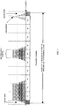
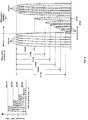
- FIG. 1 is a diagram showing an example of a frequency channel arrangement on downlink (hereinafter, referred to as "DL") in an OFDMA communication system.
- DL downlink
- OFDMA frequency channel arrangement on downlink
- subcarriers are arranged uniformly at intervals to be orthogonal to one another on the frequency axis.
- OFDMA is a scheme for allocating an optimal number of subcarriers corresponding to a required band of each user.
- OFDMA there is a case where a single frequency channel comprised of an arbitrary number of subcarriers is formed, and allocations are made on a frequency channel basis.
- a range for a receiver to be able to collectively perform demodulation is comprised of ten frequency channels.
- the frequency channels are arranged successively in principle.
- guard bands are arranged at opposite sides of the entire band.
- This is a typical DL structure, but this structure may be one unit to form the band comprised of a plurality of units.
- the entire reception band means this one unit, and the full band terminal means a terminal capable of collectively processing the entire band.
- FIG.2 is a diagram illustrating channels used by a base station and terminals in the OFDMA communication system. Shown herein is a state where in the system comprised of ten frequency channels as shown in FIG. 1 , terminal s A and B perform communication while respectively requesting five frequency channels and one frequency channel. Both A and B are capable of performing demodulation over the entire band, and by concurrently using respectively allocated five channels and one channel, implement multiple access. Thus, one channel is sometimes enough for each terminal, and it is also possible to support broadband transmission requesting maximum ten frequency channels.
- limited band terminals each of which is limited in the number of processable frequency channels and has a reception band narrower than the system bandwidth
- requirements for functions necessary for the terminals are lowered, and it is possible to realize power saving and low cost.
- needs of users are considered existing to a large extent such that speech conversation and low-rate data communication is sufficient, and introduction of the limited band terminals is thought to be significant.
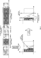
- FIG.3 shows a state where limited terminals with the reception band of one frequency channel (abbreviated as SC in the figure) and with the reception band of three frequency channels exist in the system band, while showing at the lower side the processing on the reception side of the one-frequency channel limited band terminal.
- SC reception band of one frequency channel
- the maximum frequency desired to demodulate agrees with half the sampling frequency of an analog/digital converter (hereinafter, referred to as "ADC") , and the filter attenuates with the bandwidth of the adjacent channel.
- ADC analog/digital converter
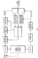
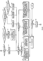
- FIG.4 is a block diagram illustrating a schematic configuration of a base station according to the first embodiment.
- a radio signal received in an antenna section 1 is converted from a radio signal to an electrical signal by a high-frequency circuit and analog processing section 2, and subjected to FFT (Fast Fourier Transform) in an FFT section3.
- FFT Fast Fourier Transform
- an equalizing section 4 corrects a reception waveform deteriorating due to delay distortion in multipath and the like, and a subcarrier demodulation section 5 performs demodulation for each subcarrier.
- a terminal reception quality information processing section 6 analyzes reception quality information received from each terminal.
- the reception quality information of frequency channels with better reception conditions on downlink, frequency channels predetermined in the system or the like
- the reception quality that the terminal is capable of measuring once is only of the limited band.
- the terminal notifies the base station of the reception information on the limited band.
- such a method may be adopted that channels are monitored and notified in a time division manner.
- the full band terminal is naturally capable of measuring the reception quality over the entire band, and reports all the results to the base station.
- such a method may be adopted that a terminal reports only the information of a better frequency channel for the terminal.
- a "base station control apparatus” via a control section 7 that controls the entire base station, inputs information to a user information storage section 8.
- the information is to determine whether a terminal accessing the base station is a full band terminal or a limited band terminal, and further includes a terminal type indicative of channels that the terminal supports and service contract information when the terminal is the limited band terminal.
- data to be transmitted to each terminal from the base station is once stored in a transmission data buffer 9 together with information indicating whether the data is of real time or not.
- a scheduling section 10 performs prioritization based on these pieces of information so as to transmit the data.
- factors for prioritization of frequency channel allocation are as follows: "Whether the data is of real time or non-real time”...a higher priority is given to real time data communication; "Optimal bandwidth”... a higher priority is given to a larger request data transfer amount; "Reception characteristics due to distance and multipath”...the quality of a reception state of a frequency channel transmitted from each terminal is compared with one another, and the frequency channel is allocated to a terminal to which data can be transmitted as much as possible; and "Typeof usedservice”...the priority varies with differences in used service systems of subscribers. For example, priorities are given in consideration of a user that suppress a basic fee per month and does not request high quality during busy hours, and service for selecting and designating quality for each call. Further, for example, in the case that the data is a real-time broadcast but the quality is not required, a lower priority is given.
- a subcarrier modulation section 11 performs modulation for each subcarrier, and a subcarrier power control section 12 controls the transmit power for each subcarrier.
- an IFFT section 13 performs IFFT (Inverse Fast Fourier Transform) processing, an electrical signal is converted into a digital signal in the high-frequency circuit and analog processing section 2, and the radio signal is transmitted from the antenna section 1.
- IFFT Inverse Fast Fourier Transform
- FIG.5 is a block diagram illustrating a configuration of the scheduling section 10 in the base station according to the first embodiment.
- Information of a terminal under communications is input to a determining section 10-1 and a terminal priority determining section 10-2 from the user information storage section 8 that has information of all terminals accessing the base station.
- the determining section 10-1 determines whether the terminal is a limited band terminal or full band terminal. Based on the real time characteristic of the data, data amounts stored in the transmission buffer 9 and the like, the terminal priority determining section 10-2 determines allocation priorities among terminals.
- a frequency channel allocating section 10-3 allocates a frequency channel for each terminal to use, modulation mode of each subcarrier, and transmit power, and outputs these items to a control signal generating section 10-4.
- the control signal generating section 10-4 outputs the frequency channel for each terminal to use, modulation mode of each subcarrier, and transmit power allocated by the frequency channel allocating section 10-3 to the transmission data buffer 9, subcarrier modulation section 11 and subcarrier power control section 12, in synchronization with the control section 7.
- FIG.6 is a diagram showing an example of a frequency channel arrangement on DL in the OFDMA communication system according to the first embodiment.
- the base station recognizes that the frequency channel allocation is for the limited band terminal, and decreases levels of the transmit power of an arbitrary number of subcarriers from the adjacent side of a frequency channel adjacent to the reception band of the terminal, or sets zero on levels of the transmit power of the subcarriers.
- the levels of the transmit power of an arbitrary number of subcarriers are decreased in opposite adjacent frequency channels of the range enabling reception of the terminal limited in the number of processable frequency channels to one frequency channel (1SC).
- the levels of the transmit power of an arbitrary number of subcarriers are decreased in opposite adjacent frequency channels of the range enabling reception of the terminal limited in the number of processable frequency channels to three frequency channels (3SC).
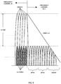
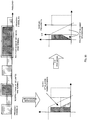
- FIG.7 is a diagram showing an example of attenuation characteristics of a filter.
- LPF low-pass filter
- the type and the order of the filter are determined depending on properties, circuit scale and the like.
- the attenuation gradient (dB/oct.) of 6dB x order is generally obtained.
- a signal band is 5MHz by performing quadrature demodulation on 10MHz, the cutoff frequency is 5MHz, and that a fifth order Butterworth filter is used.
- Gain (attenuation) is 0dB from OHz to 5MHz and flat, and since the fifth order is used, is -30dB at 10MHz. Further, intervals of subcarriers are assumed to be 50kHz.
- aliasing is -0. 15dB, next -0.45dB, -0.75dB, ... at the maximum frequency, and thus overlaps as interfering signals.
- LPF there are Butterworth, Bessel, Chebyshev, elliptic types and the like, and it is considered that the elliptic filter with steeper attenuation characteristics is suitable for the limited band terminal in the first embodiment. Even when the characteristics become steeper, it is also impossible to attenuate subcarriers close to the boarder, and it is understood that the adverse effect is produced.
- modulation rates may be decreased.
- the transmit power of a level such that a predetermined signal to noise ratio is obtained is allocated to a subcarrier to be modulated at a low modulation rate.
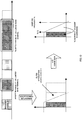
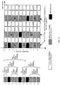
- FIG.8 is a diagram illustrating the relationship between the level of transmit power and the modulation rate.
- SNR signal to noise ratio
- BER bit error rate
- FIG.8 shown on the right side as viewed in the figure is an example of implementing the first embodiment in the BER characteristic and filter characteristics as shown in FIG.7 . This is a case that the limited band terminal is allocated to frequency channel #n, and that the full band terminal is allocated to frequency channel #n+1.
- the power of -9.15, -8.85, -8.55dB...-0.45, -0.15, 0dB is allocated successively to subcarriers closer to #n in #n+1.
- the thirty-second subcarrier is 0dB.
- modulation is allocated in the order of no modulation, BPSK, QPSK and 16QAM which is first allocated in the thirty-second subcarrier. Only one side of the frequency channel is described in the foregoing, and when a frequency channel at either edge of the entire band is not allocated, similar processing is naturally performed on opposite adjacent frequency channels to the frequency channel allocated to the limited band terminal.
- the limited band terminal allocated frequency channel #n is capable of obtaining a reception signal as shown in FIG.9 .
- the SNR is obtained that enables 16QAM to be ensured in the band.
- FIG.10 is a diagram showing an example of a frequency channel arrangement on DL in an OFDMA communication system according to the second embodiment.
- the base station recognizes that the frequency channel allocation is for a frequency channel limited band terminal, and sets zero on levels of the transmit power of all the subcarriers of a frequency channel adjacent to the reception band of the terminal. In other words, subcarriers to handle are expanded to the entire frequency channel, and it is equivalent to not allocating the power.
- the second embodiment differs from the first embodiment. In the first embodiment, another user is allocated to the adjacent frequency channel to perform the processing. In contrast thereto, in the second embodiment, any user is not allocated to the adjacent frequency channel from the beginning.
- the levels of the transmit power of all the subcarriers are set at zero in opposite adjacent frequency channels of the range enabling reception of the limited band terminal limited in the number of processable frequency channels to one frequency channel (1SC).
- the levels of the transmit power of all the subcarriers are set at zero in opposite adjacent frequency channels of the range enabling reception of the limited band terminal limited in the number of processable frequency channels to three frequency channels (3SC).
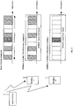
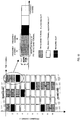
- FIG. 11 is a diagram showing an example of a communication frame in an OFDMA communication system according to the third embodiment.
- the first and second embodiments basically describe the allocation on the frequency axis.
- the method is to allocate an optimal slot to each communicating apparatus among communication slots specified by time channels and frequency channels in a single frame, and subsequently, explanations are given including the case that the present invention is applied to such an allocation on a communication frame basis.
- the communication frame is formed of ten frequency channels as frequency channels, and ten time slots as time channels. Then, as the limited band terminal, allocations are made to two one-frequency channel limited band terminals, and one two-frequency channel limited band terminal. The fifth to seventh time slots of frequency channel #2 are allocated to a user of the one-frequency channel limited band terminal, and the tenth time slot is allocated to the other user.
- the base station notified of the limited band terminal from the terminal allocates communication slots as described in the first or second embodiment to time slots 5 to 7 and 10 in frequency channels #1 and #3.
- the levels of transmit power allocated to an arbitrary number of subcarriers are decreased among subcarriers of communication slots adjacent in the frequency channel direction to the communication slot allocated to the limited band terminal.
- the levels of transmit power allocated to all the subcarriers are set at zero in communication slots adjacent in the frequency channel direction to the communication slot allocated to the limited band terminal.
- the communication slots as described in the first and second embodiments are called measures slots.
- time slots 4 of frequency channels #9 and #10 are allocated to a user of the two-frequency channel limited band terminal.
- a guard band exists out of frequency channel #10 (opposite side to frequency channel #9 in the frequency channel direction)
- only frequency channel #8 is a measures slot.
- by adaptively applying measures to adjacent slots it is possible to enhance the spectral efficiency, and introduce the limited band terminal to the same system.
- FIG.12 is a diagram illustrating frequency channel allocations to terminals limited to n frequency channels.
- frequency channels at opposite edges of the entire frequency band are preferentially allocated to the limited band terminals.
- channels are allocated starting with frequency channel #1 or #10.
- frequency channels with the need of measures slots are of only one adjacent side, and slots can be used more effectively.
- FIG.13 is a diagram illustrating frequency channel allocations to limited band terminals according to the fifth embodiment.
- a predetermined limited number of subcarriers are set for dedicated frequency channels.
- limited band terminals are allocated to be adjacent to one another to use the same time slots as possible. By this means, the measures slots can be shared, and the use efficiency of communication slots is enhanced.
- a control slot is provided at the beginning of a frame. This is because of the need of information such that what slot is allocated to which user for each frequency channel, and all the users need to be able to demodulate the control information corresponding to respective frequency channels. Since this data is modulated at a low modulation rate, it is considered that all the terminals are able to demodulate the data without particular problems even in environments that limited band terminals exist. However, by allocating as shown in FIG.13 , frequency channels with measures slots inserted therein can be fixed, and the power and the like of the control slot can be different from that of the measures slot.
- FIG.14 shows two types of specific examples of power control of the control slot.
- FIG.14 differs from FIG.13 , and shows an example of a frame structure where slots for one-limited band terminals are arranged over the entire band i.e. a frame structure where a measures slot is inserted every other frequency channel.
- a frame structure where a measures slot is inserted every other frequency channel.
- the measures frequency channels are fixed, by decreasing the power in the measures frequency channel to a certain level, or decreasing the power toward opposite edges in the band, measures are taken for making the power of the measures slot relatively lower than the power near boundaries adjacent to adjacent frequency channels near the frequency channel boundaries. It is thereby possible to compensate for the effect of aliasing also in the control information of the limited band terminal, and further improve the demodulation capability. Moreover, as can be seen from FIG. 14 , it is possible to arrange selection candidate frequency channels for limited band terminals over the entire band, and frequency channels with good reception states can be selected easier from the entire band. For the full band terminal, it is also considered that the terminal is not affected by low power due to the low modulation rate.
- even-numbered frequency channels are measures frequency channels, and it is naturally considered that the odd number and the even number are switched at any timing. Further, when the number of all frequency channels is an odd number, it is possible to perform optimal allocations.
- FIG.15 is a diagram showing an example of power control of control slots and a terminal allocation method.
- the allocation of frequency channels is the same as in FIG. 14 . Accordingly, the power of the control channel is made high and low repeatedly every frequency channel.
- FIG.15 shows allocations of one-limited, three-limited and five-limited band terminals in this frame. By performing power control of the control channel in this pattern, it is possible to send the control information on all the channels, and the limited band terminals can exist almost evenly over the entire band.
- FIG.16 is a diagram showing an example of a communication frame in an OFDMA communication system according to the sixth embodiment.
- the base station In allocating a frequency channel adjacent to a frequency channel allocated to an n-limited band terminal to another terminal, the base station does not give the power to an arbitrary number of subcarriers inward from the opposite edges of the frequency range that the limited band terminal is capable of receiving.
- This is a scheme that the terminal notifies the base station of the information that the quality is poor in an arbitrary number of subcarriers, and that the power is thereby not allocated to the subcarriers under the initiative of the limited band terminal.
- FIG.17 is a block diagram illustrating a schematic configuration of a mobile terminal according to the six embodiment.
- a radio signal received in an antenna section 161 is converted from a high-frequency signal to a baseband signal in a high-frequency circuit section 162 and delivered to a propagation path estimating section 163 that estimates distortion on the propagation path and an FFT section 164 that performs FFT (Fast Fourier Transform).
- an equalizing section 165 compensates a reception signal for deterioration due to delay distortion by multipath and the like based on the propagation path estimation result, and a subcarrier demodulation section 166 performs demodulation for each subcarrier.
- a terminal reception quality information data generating section 167 generates reception quality information based on the information from the propagation path estimating section 163.
- the data generated in the terminal reception quality information data generating section 167 is output as part of transmission data from a control section 168 to a transmission signal processing section 169, and via the high-frequency circuit section 162, and antenna section 161, transmitted to a communicating apparatus.
- the mobile terminal as shown in FIG.17 transmits to the base station a desired frequency channel and the information that lower b subcarriers and upper b subcarriers on the frequency channel are always poor in reception state. By this means, the base station does not need to consider allocations to adjacent frequency channels.
- FIGs.18 and 19 are flowcharts illustrating the operation of the base station according to the sixth embodiment.
- "k” is “0” or “1”, and immediately after starting the allocation, is only “0". Using k, required transmission bands are obtained for all the terminals, while provisional allocations are made to limited band terminals.
- "i” is an integer, the loop is circulated in the number of terminals, and priorities are determined.
- "j” is an integer, and used in searching for a terminal with the highest priority at this point.
- B indicates the total requested transmission band from terminals left without allocations.
- a priority is determined for each terminal, while entire required bit rates are obtained.
- MT (i) is not FSCT i.e. is LSCT
- required time slots of a desired frequency channel are provisionally allocated to the LSCT (limited band terminal) (step T5) .
- NMT the number of terminal in access
- C is set at NMT-the number of all LSCTs.
- required time slots of a desired frequency channel are allocated to FSCT, and in the case of shortage, a frequency channel that is not desired is also allocated to compensate (step T12). Then, the processing is finished.
- step T14 it is determined whether the terminal is FSCT (step T16).
- step T17 When the terminal is FSCT, it is determined whether a desired vacant frequency channel exists (step T17), and when the desired vacant frequency channel exists, a slot of the desired frequency channel is allocated (step T18). In other words, bit rate b obtained by this allocation is entered at one slot allocation ARB.
- step T16 it is determined whether a provisionally allocated slot of MT(j) exists, and when the provisionally allocated slot of MT(j) exists, the provisionally allocated slot is determined to be actually allocated (step T20). Meanwhile, when any provisionally allocated slot does not exist in step T19, no allocation is determined (step T21). In other words, bit rate z obtained by this allocation is entered at one slot allocation ARB.
- step T17 it is determined whether another vacant frequency channel of a good reception state exists (step T22) .
- step T23 a slot of the frequency channel is allocated (step T23). In other words, bit rate c obtained by this allocation is entered at one slot allocation ARB.
- step T24 it is determined whether a reception state is good in the frequency channel provisionally allocated to the LSCT (step T24).
- a slot of the frequency channel is allocated (step T25). In other words, bit rate d obtained by this allocation is entered at one slot allocation ARB.
- step T28 it is determined whether a vacant slot that can be allocated exists
- FIG. 20 is a diagram showing an example of a communication frame in an OFDMA communication system according to the seventh embodiment.
- the base station detects the reception power for each terminal. Then, in allocating another terminal to an adjacent channel of the frequency channel allocated to a limited band terminal, the base station allocates a terminal with high reception power because the terminal exists closer to the base station and the like. Then, the transmit power of the slot is set to be lower than the power of the frequency channel allocated to the limited band terminal. It is possible to use such control of transmit power together with each of the above-mentioned embodiments.
- FIGs.21 and 22 are flowcharts illustrating the operation of the base station according to the eighth embodiment.
- "k” is to increment a priority to handle for each loop.
- "i” is an integer and used in a loop to determine a priority of a terminal and handle in the order of priority.
- B indicates the total requested transmission band from terminals left without allocations.
- “NLSC” indicates the number of limited frequency channels of a limited band terminal.
- NRSC indicates the number of frequency channels that each terminal requests.
- GSH is "0” or “1”, and represents implementing measures for an upper (higher frequency) adjacent frequency channel when "1", while representing no need of such measures when "0".
- GBL is "0” or "1”, and represents implementing measures for a lower (lower frequency) adjacent frequency channel when "1", while representing no need of such measures when "0".
- "k” and “i” in FIGs.21 and 22 are used in different meaning from that of "k” and “i” in FIGs.18 and 19 .
- a priority for each terminal is determined in a first loop, while entire required bit rates are obtained.
- step S6 it is determined whether B ⁇ TLIM (criterion by which to judge a degree of traffic congestion) holds (step S6).
- B ⁇ TLIM criteria by which to judge a degree of traffic congestion
- step S11 it is determined whether the terminal is FSCT (full band terminal) (step S11), and when the terminal is FSCT, GBH and GBL are set at zero (step S12).
- step S11 when the terminal is not FSCT i.e. is LSCT (limited band terminal), in the case that an interval between the maximum and minimum requested channels is narrower than a number of limited channels by two frequency channels or more, the need is eliminated of providing measures frequency channels out of the band by setting an allocation not to allocate opposite sides of the limited band, and GBH and GBL are also zero.
- FSCT i.e. is LSCT
- GBH and GBL are also zero.
- step S19 it is determined whether RSC# includes SCH#min (step S19).
- time slots are allocated so that the terminal secures requested frequency channels up to a required bit rate.
- the levels of transmit power are decreased in all or part of subcarriers of a communication slot that is adjacent on the frequency channel side to a communication slot allocated to the communicating apparatus and that is not allocated to the communicating apparatus in a communication frame. Therefore, in the case of using a low sampling frequency for low power consumption in the communicating apparatus, it is also possible to reduce an effect of the adjacent communication slot in the frequency channel direction. It is thereby possible to implement wireless communication also with the communicating apparatus limited in the frequency band that the communicating apparatus is capable of collectively process.
Claims (4)
- Appareil de communication sans fil qui réalise une communication sans fil dans un schéma de transmission à porteuses multiples au moyen d'une pluralité de canaux de fréquence, chacun d'un groupe d'un nombre prédéterminé de sous-porteuses parmi une pluralité de sous-porteuses disposées successivement à des intervalles de fréquence réguliers dans une bande de système, l'appareil comprenant :une section d'attribution de canaux de fréquence (10) qui attribue les canaux de fréquence à des terminaux en communication ;une section de contrôle de puissance de sous-porteuse (12) qui contrôle, au moins, s'il faut régler ou non à zéro la puissance de transmission de chaque sous-porteuse ; etune section de détermination (10) qui vérifie une bande passante de réception du terminal en communication, pendant qu'il est déterminé si le terminal en communication est un terminal à pleine bande capable de recevoir tous les canaux de fréquence dans la bande de système ou est un terminal à bande limitée capable de recevoir uniquement une partie des canaux de fréquence dans la bande de système,suite à la détermination, quand le terminal en communication est le terminal à bande limitée, la section de contrôle de puissance de sous-porteuse réalisant un contrôle pour régler à zéro la puissance de transmission d'une partie des sous-porteuses d'un canal de fréquence qui est adjacent à une bande de réception attribuée au terminal de communication et qui est attribué à un autre terminal de communication, ou la section de contrôle de puissance de sous-porteuse réalisant un contrôle pour régler à zéro la puissance de transmission de toutes les sous-porteuses d'un canal de fréquence qui est adjacent à une bande de réception attribuée au terminal de communication.
- Appareil de communication sans fil selon la revendication 1, dans lequel, quand le terminal en communication est le terminal à bande limitée, la section d'attribution de canal de fréquence (10) réalise de préférence une attribution de canal de fréquence de sorte qu'au moins une périphérie de la bande de réception du terminal en communication soit un canal de fréquence au niveau d'une périphérie de la bande de système.
- Procédé de communication sans fil pour la réalisation d'une communication sans fil dans un schéma de transmission à porteuses multiples au moyen d'une pluralité de canaux de fréquence, chacun d'un groupe d'un nombre prédéterminé de sous-porteuses parmi une pluralité de sous-porteuses disposées successivement à des intervalles de fréquence réguliers dans une bande de système, le procédé comprenant au moins les étapes consistant à :vérifier une bande passante de réception d'un terminal en communication, pendant qu'il est déterminé si le terminal en communication est un terminal à pleine bande capable de recevoir tous les canaux de fréquence dans la bande de système ou est un terminal à bande limitée capable de recevoir uniquement une partie des canaux de fréquence dans la bande de système ; etsuite à la détermination, quand le terminal de communication est le terminal à bande limitée, réaliser un contrôle pour régler à zéro la puissance de transmission d'une partie des sous-porteuses d'un canal de fréquence qui est adjacent à une bande de réception attribuée au terminal de communication et qui est attribué à un autre terminal de communication, ou réaliser un contrôle pour régler à zéro la puissance de transmission de toutes les sous-porteuses d'un canal de fréquence qui est adjacent à une bande de réception attribuée au terminal de communication.
- Procédé de communication sans fil selon la revendication 3, comprenant en outre, quand le terminal de communication est le terminal à bande limitée, l'étape consistant à réaliser de préférence une attribution de canal de fréquence de sorte qu'au moins une périphérie de la bande de réception de la partie de communication soit une fréquence au niveau d'une périphérie de la bande de système.
Priority Applications (2)
| Application Number | Priority Date | Filing Date | Title |
|---|---|---|---|
| EP19157248.6A EP3544217B1 (fr) | 2005-01-18 | 2005-12-02 | Appareil de communication sans fil et méthode de communication sans fil |
| EP12190896.6A EP2555464B1 (fr) | 2005-01-18 | 2005-12-02 | Appareil de Communication Sans Fil et Méthode de Communication Sans Fil |
Applications Claiming Priority (2)
| Application Number | Priority Date | Filing Date | Title |
|---|---|---|---|
| JP2005010252 | 2005-01-18 | ||
| PCT/JP2005/022212 WO2006077696A1 (fr) | 2005-01-18 | 2005-12-02 | Appareil de communication sans fil, terminal mobile et méthode de communication sans fil |
Related Child Applications (3)
| Application Number | Title | Priority Date | Filing Date |
|---|---|---|---|
| EP19157248.6A Division EP3544217B1 (fr) | 2005-01-18 | 2005-12-02 | Appareil de communication sans fil et méthode de communication sans fil |
| EP12190896.6A Division-Into EP2555464B1 (fr) | 2005-01-18 | 2005-12-02 | Appareil de Communication Sans Fil et Méthode de Communication Sans Fil |
| EP12190896.6A Division EP2555464B1 (fr) | 2005-01-18 | 2005-12-02 | Appareil de Communication Sans Fil et Méthode de Communication Sans Fil |
Publications (3)
| Publication Number | Publication Date |
|---|---|
| EP1843497A1 EP1843497A1 (fr) | 2007-10-10 |
| EP1843497A4 EP1843497A4 (fr) | 2012-08-22 |
| EP1843497B1 true EP1843497B1 (fr) | 2018-06-20 |
Family
ID=36692090
Family Applications (3)
| Application Number | Title | Priority Date | Filing Date |
|---|---|---|---|
| EP19157248.6A Active EP3544217B1 (fr) | 2005-01-18 | 2005-12-02 | Appareil de communication sans fil et méthode de communication sans fil |
| EP05811779.7A Active EP1843497B1 (fr) | 2005-01-18 | 2005-12-02 | Appareil de communication sans fil et méthode de communication sans fil |
| EP12190896.6A Active EP2555464B1 (fr) | 2005-01-18 | 2005-12-02 | Appareil de Communication Sans Fil et Méthode de Communication Sans Fil |
Family Applications Before (1)
| Application Number | Title | Priority Date | Filing Date |
|---|---|---|---|
| EP19157248.6A Active EP3544217B1 (fr) | 2005-01-18 | 2005-12-02 | Appareil de communication sans fil et méthode de communication sans fil |
Family Applications After (1)
| Application Number | Title | Priority Date | Filing Date |
|---|---|---|---|
| EP12190896.6A Active EP2555464B1 (fr) | 2005-01-18 | 2005-12-02 | Appareil de Communication Sans Fil et Méthode de Communication Sans Fil |
Country Status (5)
| Country | Link |
|---|---|
| US (7) | US8150442B2 (fr) |
| EP (3) | EP3544217B1 (fr) |
| JP (6) | JPWO2006077696A1 (fr) |
| CN (3) | CN102307379B (fr) |
| WO (1) | WO2006077696A1 (fr) |
Families Citing this family (74)
| Publication number | Priority date | Publication date | Assignee | Title |
|---|---|---|---|---|
| US7295509B2 (en) | 2000-09-13 | 2007-11-13 | Qualcomm, Incorporated | Signaling method in an OFDM multiple access system |
| US9130810B2 (en) | 2000-09-13 | 2015-09-08 | Qualcomm Incorporated | OFDM communications methods and apparatus |
| US9137822B2 (en) | 2004-07-21 | 2015-09-15 | Qualcomm Incorporated | Efficient signaling over access channel |
| US9148256B2 (en) | 2004-07-21 | 2015-09-29 | Qualcomm Incorporated | Performance based rank prediction for MIMO design |
| WO2006046307A1 (fr) * | 2004-10-29 | 2006-05-04 | Fujitsu Limited | Dispositif de communication par la méthode de transmission par multiporteuse et système de communication |
| EP1814251A4 (fr) | 2004-10-29 | 2012-06-27 | Sharp Kk | Méthode de communication et émetteur radio |
| US8150442B2 (en) | 2005-01-18 | 2012-04-03 | Sharp Kabushiki Kaisha | Method and apparatus for controlling power of subcarriers in a wireless communication system |
| US9246560B2 (en) | 2005-03-10 | 2016-01-26 | Qualcomm Incorporated | Systems and methods for beamforming and rate control in a multi-input multi-output communication systems |
| US9154211B2 (en) | 2005-03-11 | 2015-10-06 | Qualcomm Incorporated | Systems and methods for beamforming feedback in multi antenna communication systems |
| US8446892B2 (en) | 2005-03-16 | 2013-05-21 | Qualcomm Incorporated | Channel structures for a quasi-orthogonal multiple-access communication system |
| US9520972B2 (en) | 2005-03-17 | 2016-12-13 | Qualcomm Incorporated | Pilot signal transmission for an orthogonal frequency division wireless communication system |
| US9143305B2 (en) | 2005-03-17 | 2015-09-22 | Qualcomm Incorporated | Pilot signal transmission for an orthogonal frequency division wireless communication system |
| US9461859B2 (en) | 2005-03-17 | 2016-10-04 | Qualcomm Incorporated | Pilot signal transmission for an orthogonal frequency division wireless communication system |
| US9184870B2 (en) | 2005-04-01 | 2015-11-10 | Qualcomm Incorporated | Systems and methods for control channel signaling |
| US9036538B2 (en) | 2005-04-19 | 2015-05-19 | Qualcomm Incorporated | Frequency hopping design for single carrier FDMA systems |
| US9408220B2 (en) | 2005-04-19 | 2016-08-02 | Qualcomm Incorporated | Channel quality reporting for adaptive sectorization |
| US8565194B2 (en) | 2005-10-27 | 2013-10-22 | Qualcomm Incorporated | Puncturing signaling channel for a wireless communication system |
| US8879511B2 (en) | 2005-10-27 | 2014-11-04 | Qualcomm Incorporated | Assignment acknowledgement for a wireless communication system |
| US8611284B2 (en) | 2005-05-31 | 2013-12-17 | Qualcomm Incorporated | Use of supplemental assignments to decrement resources |
| US8462859B2 (en) | 2005-06-01 | 2013-06-11 | Qualcomm Incorporated | Sphere decoding apparatus |
| US8599945B2 (en) | 2005-06-16 | 2013-12-03 | Qualcomm Incorporated | Robust rank prediction for a MIMO system |
| US9179319B2 (en) | 2005-06-16 | 2015-11-03 | Qualcomm Incorporated | Adaptive sectorization in cellular systems |
| US8885628B2 (en) | 2005-08-08 | 2014-11-11 | Qualcomm Incorporated | Code division multiplexing in a single-carrier frequency division multiple access system |
| US20070041457A1 (en) | 2005-08-22 | 2007-02-22 | Tamer Kadous | Method and apparatus for providing antenna diversity in a wireless communication system |
| US9209956B2 (en) | 2005-08-22 | 2015-12-08 | Qualcomm Incorporated | Segment sensitive scheduling |
| US8644292B2 (en) | 2005-08-24 | 2014-02-04 | Qualcomm Incorporated | Varied transmission time intervals for wireless communication system |
| US9136974B2 (en) | 2005-08-30 | 2015-09-15 | Qualcomm Incorporated | Precoding and SDMA support |
| US9172453B2 (en) | 2005-10-27 | 2015-10-27 | Qualcomm Incorporated | Method and apparatus for pre-coding frequency division duplexing system |
| US8045512B2 (en) | 2005-10-27 | 2011-10-25 | Qualcomm Incorporated | Scalable frequency band operation in wireless communication systems |
| US9210651B2 (en) | 2005-10-27 | 2015-12-08 | Qualcomm Incorporated | Method and apparatus for bootstraping information in a communication system |
| US9225488B2 (en) | 2005-10-27 | 2015-12-29 | Qualcomm Incorporated | Shared signaling channel |
| US8693405B2 (en) | 2005-10-27 | 2014-04-08 | Qualcomm Incorporated | SDMA resource management |
| US8477684B2 (en) | 2005-10-27 | 2013-07-02 | Qualcomm Incorporated | Acknowledgement of control messages in a wireless communication system |
| US9088384B2 (en) | 2005-10-27 | 2015-07-21 | Qualcomm Incorporated | Pilot symbol transmission in wireless communication systems |
| US8582509B2 (en) * | 2005-10-27 | 2013-11-12 | Qualcomm Incorporated | Scalable frequency band operation in wireless communication systems |
| US9225416B2 (en) | 2005-10-27 | 2015-12-29 | Qualcomm Incorporated | Varied signaling channels for a reverse link in a wireless communication system |
| US9144060B2 (en) | 2005-10-27 | 2015-09-22 | Qualcomm Incorporated | Resource allocation for shared signaling channels |
| US8582548B2 (en) | 2005-11-18 | 2013-11-12 | Qualcomm Incorporated | Frequency division multiple access schemes for wireless communication |
| US8831607B2 (en) | 2006-01-05 | 2014-09-09 | Qualcomm Incorporated | Reverse link other sector communication |
| AU2007200144A1 (en) * | 2006-01-18 | 2007-08-02 | Nec Australia Pty Ltd | Method and system for supporting scalable bandwidth |
| KR20100123918A (ko) * | 2006-02-08 | 2010-11-25 | 콸콤 인코포레이티드 | 유니캐스트 및 멀티캐스트 전송들의 다중화 방법 |
| US9622190B2 (en) | 2006-07-25 | 2017-04-11 | Google Technology Holdings LLC | Spectrum emission level variation in schedulable wireless communication terminal |
| US9167423B2 (en) * | 2006-09-29 | 2015-10-20 | Rosemount Inc. | Wireless handheld configuration device for a securable wireless self-organizing mesh network |
| JP5201604B2 (ja) * | 2006-09-29 | 2013-06-05 | ローズマウント インコーポレイテッド | Tdma通信のためのマルチサイズのタイムスロットをもつ無線メッシュネットワーク |
| JP4891752B2 (ja) * | 2006-12-19 | 2012-03-07 | 株式会社東芝 | 無線通信装置および無線通信方法 |
| WO2008126550A1 (fr) * | 2007-03-13 | 2008-10-23 | Sharp Kabushiki Kaisha | Procédé de planification, transmetteur et récepteur radio |
| JP4912936B2 (ja) * | 2007-03-29 | 2012-04-11 | 京セラ株式会社 | 無線通信方法、無線通信システムおよび基地局 |
| JP5185561B2 (ja) * | 2007-04-16 | 2013-04-17 | 株式会社エヌ・ティ・ティ・ドコモ | 通信装置および通信方法 |
| JP4874178B2 (ja) * | 2007-07-02 | 2012-02-15 | シャープ株式会社 | 無線送信方法、伝搬路推定方法、無線送信機、無線受信機および無線通信システム |
| US8532689B2 (en) * | 2007-10-31 | 2013-09-10 | Telefonaktiebolaget L M Ericsson (Publ) | Transmission behaviour for support of cell measurements |
| JP4911780B2 (ja) * | 2007-12-20 | 2012-04-04 | シャープ株式会社 | 無線通信システム、受信装置及び受信方法 |
| US8868096B2 (en) | 2008-04-30 | 2014-10-21 | Alexander Poltorak | Multi-tier quality of service wireless communications networks |
| JP5156485B2 (ja) * | 2008-05-28 | 2013-03-06 | 株式会社エヌ・ティ・ティ・ドコモ | 無線通信システム |
| CN101399772B (zh) * | 2008-10-20 | 2012-07-04 | 中兴通讯股份有限公司 | 基于多载波的带宽分配方法和装置 |
| US8014326B2 (en) * | 2009-01-26 | 2011-09-06 | Mitsubishi Electric Research Laboratories, Inc. | Joint carrier allocation and time sharing for OFDMA/TDMA networks |
| US8717992B2 (en) * | 2009-03-10 | 2014-05-06 | Sharp Kabushiki Kaisha | Wireless communication system, wireless transmission apparatus and wireless transmission method |
| WO2011112131A1 (fr) * | 2010-03-12 | 2011-09-15 | Telefonaktiebolaget L M Ericsson (Publ) | Procédés et appareils pour un accès multiple dans un réseau de communication sans fil via dct-ofdm |
| KR101671287B1 (ko) * | 2010-08-13 | 2016-11-01 | 삼성전자 주식회사 | 무선 통신 시스템에서 기준 신호 송수신 방법 및 장치 |
| FR2968149B1 (fr) | 2010-11-30 | 2013-03-15 | Thales Sa | Procede et systeme de communications adaptatives en bande hf |
| US8626227B2 (en) * | 2010-12-13 | 2014-01-07 | Fujitsu Limited | Method and system for power allocation in a transmission system |
| US8638742B2 (en) | 2011-01-12 | 2014-01-28 | Telefonaktiebolaget L M Ericsson (Publ) | Data resource mapping for frequency-coded symbols |
| GB2487909B8 (en) | 2011-02-04 | 2015-01-21 | Sca Ipla Holdings Inc | Telecommunications method and system |
| US9565655B2 (en) * | 2011-04-13 | 2017-02-07 | Google Technology Holdings LLC | Method and apparatus to detect the transmission bandwidth configuration of a channel in connection with reducing interference between channels in wireless communication systems |
| EP2533453B1 (fr) * | 2011-06-10 | 2015-08-19 | Sony Corporation | Appareil et procédé de transmission et de réception pour un système de transmission avec porteuses multiples |
| WO2012159327A1 (fr) * | 2011-07-13 | 2012-11-29 | 华为技术有限公司 | Procédé de commande et appareil de gestion des ressources d'un amplificateur de puissance à fréquence multi-porteuse |
| US8918136B2 (en) | 2012-11-29 | 2014-12-23 | At&T Mobility Ii Llc | Adjustment of transmit power parameter |
| US9204385B2 (en) | 2013-10-09 | 2015-12-01 | Netgear, Inc. | Wireless router or residential gateway capable of distinguishing power-sensitive wireless sensors and providing separate treatment thereto |
| EP2963971B1 (fr) * | 2014-07-02 | 2017-08-30 | Nec Corporation | Procédé et système pour contrôler des messages entre des entités communicantes |
| WO2016050281A1 (fr) * | 2014-09-30 | 2016-04-07 | Nokia Solutions And Networks Oy | Procédé et appareil pour le suivi de dispositifs au repos |
| US10797918B2 (en) * | 2015-07-06 | 2020-10-06 | Telefonaktiebolaget Lm Ericsson (Publ) | Resource allocation for data transmission in wireless systems |
| JP6801914B2 (ja) * | 2016-02-03 | 2020-12-16 | Necプラットフォームズ株式会社 | モバイルルータ、モバイルルータの通信方法及びその通信方法を実現するプログラム |
| TWI699093B (zh) * | 2018-11-07 | 2020-07-11 | 聯發科技股份有限公司 | 通訊接收裝置及其信號處理方法 |
| JPWO2021009992A1 (fr) | 2019-07-12 | 2021-01-21 | ||
| US11711862B1 (en) | 2021-07-15 | 2023-07-25 | T-Mobile Usa, Inc. | Dual connectivity and carrier aggregation band selection |
Family Cites Families (154)
| Publication number | Priority date | Publication date | Assignee | Title |
|---|---|---|---|---|
| US4122415A (en) | 1977-03-21 | 1978-10-24 | Rca Corporation | AM transmitter with an offset voltage to the RF stage to compensate for switching time of the modulators |
| JPH01127231A (ja) | 1987-11-11 | 1989-05-19 | Hoden Seimitsu Kako Kenkyusho Ltd | ワイヤ放電加工機のワイヤ廃棄処理装置 |
| US6334219B1 (en) | 1994-09-26 | 2001-12-25 | Adc Telecommunications Inc. | Channel selection for a hybrid fiber coax network |
| US5621723A (en) | 1994-09-27 | 1997-04-15 | Gte Laboratories Incorporated | Power control in a CDMA network |
| US20010055320A1 (en) * | 1994-12-15 | 2001-12-27 | Pierzga Wayne Francis | Multiplex communication |
| US5857153A (en) | 1995-10-13 | 1999-01-05 | Telefonaktiebolaget Lm Ericsson (Publ) | Cellular telecommunications network having seamless interoperability between exchanges while providing voice, asynchronous data and facsimile services in multiple frequency hyperbands |
| JP3780551B2 (ja) | 1996-01-29 | 2006-05-31 | ソニー株式会社 | 多元接続による信号送信方法及び装置 |
| US6014412A (en) | 1996-04-19 | 2000-01-11 | Amati Communications Corporation | Digital radio frequency interference canceller |
| US5995567A (en) | 1996-04-19 | 1999-11-30 | Texas Instruments Incorporated | Radio frequency noise canceller |
| US6035000A (en) | 1996-04-19 | 2000-03-07 | Amati Communications Corporation | Mitigating radio frequency interference in multi-carrier transmission systems |
| JPH1066039A (ja) | 1996-08-23 | 1998-03-06 | Sony Corp | 通信方法、送信装置、送信方法、受信装置及び受信方法 |
| JP2001359152A (ja) | 2000-06-14 | 2001-12-26 | Sony Corp | 無線通信システム、無線基地局装置、無線移動局装置、無線ゾーン割当て方法及び無線通信方法 |
| JP4040125B2 (ja) | 1996-09-18 | 2008-01-30 | ソニー株式会社 | 音声信号記録装置 |
| US6061568A (en) | 1996-10-01 | 2000-05-09 | Ericsson Inc. | Method and apparatus for mitigating intermodulation effects in multiple-signal transmission systems |
| JPH10190612A (ja) | 1996-12-26 | 1998-07-21 | Sony Corp | 通信方法及び受信装置 |
| JPH10191431A (ja) | 1996-12-26 | 1998-07-21 | Sony Corp | 通信方法、基地局及び端末装置 |
| DE19654955C2 (de) * | 1996-12-27 | 2000-11-16 | Albert Bauer | Klimatisierungsvorrichtung |
| JPH10276165A (ja) | 1997-03-27 | 1998-10-13 | Sanyo Electric Co Ltd | Ofdm信号受信機 |
| JP3565537B2 (ja) | 1997-06-18 | 2004-09-15 | 株式会社日立国際電気 | 直交周波数分割多重変調信号の伝送方式 |
| JP3670445B2 (ja) | 1997-06-30 | 2005-07-13 | 株式会社東芝 | 無線通信システム |
| JP3615909B2 (ja) | 1997-06-30 | 2005-02-02 | 三菱重工業株式会社 | 移動物体検出装置 |
| EP0899923A1 (fr) * | 1997-08-29 | 1999-03-03 | Sony International (Europe) GmbH | Transmission de signaux de réglage de puissance dans un système à modulation multiporteuse |
| DE69733313T2 (de) * | 1997-11-07 | 2006-01-19 | Sony International (Europe) Gmbh | Mehrträgerübertragung, kompatibel zum existierenden GSM-System |
| JPH11154925A (ja) | 1997-11-21 | 1999-06-08 | Hitachi Denshi Ltd | ディジタル伝送装置 |
| JP3647628B2 (ja) | 1997-12-26 | 2005-05-18 | 昭和電線電纜株式会社 | サテライト型全二重赤外線lanシステム |
| JP3778397B2 (ja) * | 1997-12-27 | 2006-05-24 | ソニー株式会社 | 送信方法、送信電力制御方法及び基地局装置 |
| JPH11205276A (ja) | 1998-01-20 | 1999-07-30 | Nippon Telegr & Teleph Corp <Ntt> | マルチキャリア変調装置 |
| EP1072136B1 (fr) * | 1998-04-14 | 2002-01-16 | Fraunhofer-Gesellschaft zur Förderung der angewandten Forschung e.V. | Correction d'erreur de phase d'echo dans un systeme a porteuses multiples |
| JP3515690B2 (ja) | 1998-06-02 | 2004-04-05 | 松下電器産業株式会社 | Ofdma信号伝送装置及び方法 |
| JP3957882B2 (ja) | 1998-06-17 | 2007-08-15 | 株式会社日立コミュニケーションテクノロジー | 電力制御方法及び電力制御装置 |
| CN1241880A (zh) * | 1998-07-01 | 2000-01-19 | 诺基亚流动电话有限公司 | 数据传输方法和无线电系统 |
| JP4287536B2 (ja) * | 1998-11-06 | 2009-07-01 | パナソニック株式会社 | Ofdm送受信装置及びofdm送受信方法 |
| US6741551B1 (en) | 1999-01-11 | 2004-05-25 | International Business Machines Corporation | Hybrid TDMA/CDMA system based on filtered multitone modulation |
| JP2000354266A (ja) | 1999-06-11 | 2000-12-19 | Sony Corp | 無線通信端末装置 |
| JP4315530B2 (ja) | 1999-07-29 | 2009-08-19 | 富士通株式会社 | 非接触icカードデバイスのための検波回路 |
| JP2001238251A (ja) | 2000-02-23 | 2001-08-31 | Nec Corp | セルラシステムの隣接キャリア周波数干渉回避方法、移動局、及び基地局制御装置 |
| JP4323669B2 (ja) | 2000-03-15 | 2009-09-02 | パナソニック株式会社 | データ伝送装置及びデータ伝送方法 |
| JP2001313628A (ja) | 2000-04-28 | 2001-11-09 | Sony Corp | Ofdm受信装置及び方法 |
| US7013145B1 (en) | 2000-08-22 | 2006-03-14 | Cellco Partnership | Methods and apparatus for utilizing radio frequency spectrum simultaneously and concurrently in the presence of co-channel and/or adjacent channel television signals by adjusting transmitter power or receiver sensitivity |
| US7009931B2 (en) * | 2000-09-01 | 2006-03-07 | Nortel Networks Limited | Synchronization in a multiple-input/multiple-output (MIMO) orthogonal frequency division multiplexing (OFDM) system for wireless applications |
| US6721569B1 (en) * | 2000-09-29 | 2004-04-13 | Nortel Networks Limited | Dynamic sub-carrier assignment in OFDM systems |
| US6834079B1 (en) | 2000-10-20 | 2004-12-21 | 3Com Corporation | Efficient implementation for equalization of multicarrier channels |
| JP3550085B2 (ja) | 2000-11-01 | 2004-08-04 | 松下電器産業株式会社 | 無線送信装置および無線送信方法 |
| US6947748B2 (en) | 2000-12-15 | 2005-09-20 | Adaptix, Inc. | OFDMA with adaptive subcarrier-cluster configuration and selective loading |
| US7054375B2 (en) | 2000-12-22 | 2006-05-30 | Nokia Corporation | Method and apparatus for error reduction in an orthogonal modulation system |
| JP4242553B2 (ja) * | 2000-12-28 | 2009-03-25 | ヤマハ株式会社 | ディジタルオーディオ信号録音装置 |
| US20020085641A1 (en) | 2000-12-29 | 2002-07-04 | Motorola, Inc | Method and system for interference averaging in a wireless communication system |
| US7002934B2 (en) | 2001-01-22 | 2006-02-21 | Unique Broadband Systems, Inc. | OFDM multiple upstream receiver network |
| JP4496673B2 (ja) | 2001-06-07 | 2010-07-07 | 株式会社デンソー | Ofdm方式の送受信機 |
| US7206350B2 (en) * | 2001-06-11 | 2007-04-17 | Unique Broadband Systems, Inc. | OFDM multiple sub-channel communication system |
| US7594010B2 (en) | 2001-06-28 | 2009-09-22 | King's London College | Virtual antenna array |
| JP2003087218A (ja) | 2001-06-29 | 2003-03-20 | Matsushita Electric Ind Co Ltd | マルチキャリア送信装置、マルチキャリア受信装置およびマルチキャリア無線通信方法 |
| JP3607643B2 (ja) * | 2001-07-13 | 2005-01-05 | 松下電器産業株式会社 | マルチキャリア送信装置、マルチキャリア受信装置、およびマルチキャリア無線通信方法 |
| US7272175B2 (en) | 2001-08-16 | 2007-09-18 | Dsp Group Inc. | Digital phase locked loop |
| US20030039226A1 (en) | 2001-08-24 | 2003-02-27 | Kwak Joseph A. | Physical layer automatic repeat request (ARQ) |
| TWI261984B (en) * | 2001-08-24 | 2006-09-11 | Interdigital Tech Corp | Implementing a physical layer automatic repeat request for a subscriber unit |
| JPWO2003021809A1 (ja) * | 2001-09-03 | 2004-12-24 | 三菱電機株式会社 | 無線移動機における送信電力制御方法 |
| JP2003101499A (ja) | 2001-09-25 | 2003-04-04 | Victor Co Of Japan Ltd | マルチキャリア信号の生成方法、マルチキャリア信号の復号方法、マルチキャリア信号生成装置、及びマルチキャリア信号復号装置 |
| US7289476B2 (en) | 2001-10-16 | 2007-10-30 | Nokia Corporation | Method and system to increase QoS and range in a multicarrier system |
| US6563885B1 (en) * | 2001-10-24 | 2003-05-13 | Texas Instruments Incorporated | Decimated noise estimation and/or beamforming for wireless communications |
| US20030093526A1 (en) | 2001-11-13 | 2003-05-15 | Koninklijke Philips Electronics N. V. | Apparatus and method for providing quality of service signaling for wireless mac layer |
| JP3727283B2 (ja) | 2001-11-26 | 2005-12-14 | 松下電器産業株式会社 | 無線送信装置、無線受信装置及び無線送信方法 |
| JP3875086B2 (ja) | 2001-11-30 | 2007-01-31 | ソフトバンクテレコム株式会社 | 直交周波数分割多重システムおよび送受信装置 |
| JP3693025B2 (ja) | 2002-02-21 | 2005-09-07 | ソニー株式会社 | 無線通信方法、無線通信システム、無線基地局、無線通信端末、プログラム及び媒体 |
| JP2003259448A (ja) | 2002-02-28 | 2003-09-12 | Sony Corp | 無線通信方法、無線通信システム、無線基地局、無線通信端末、プログラム及び媒体 |
| US7630403B2 (en) | 2002-03-08 | 2009-12-08 | Texas Instruments Incorporated | MAC aggregation frame with MSDU and fragment of MSDU |
| US7224704B2 (en) | 2002-04-01 | 2007-05-29 | Texas Instruments Incorporated | Wireless network scheduling data frames including physical layer configuration |
| AU2003226934A1 (en) | 2002-04-10 | 2003-10-27 | Disop-Nordic Holding Aps | Tube with self-closing mechanism for liquid container |
| US20030193889A1 (en) | 2002-04-11 | 2003-10-16 | Intel Corporation | Wireless device and method for interference and channel adaptation in an OFDM communication system |
| JP2003309533A (ja) | 2002-04-17 | 2003-10-31 | Matsushita Electric Ind Co Ltd | 無線送信装置、無線受信装置及びその方法 |
| JP2003333008A (ja) | 2002-05-10 | 2003-11-21 | Sony Corp | 通信システムおよびその方法、受信装置およびその方法、通信装置およびその方法、ならびにプログラム |
| US7200178B2 (en) | 2002-06-12 | 2007-04-03 | Texas Instruments Incorporated | Methods for optimizing time variant communication channels |
| US7095709B2 (en) | 2002-06-24 | 2006-08-22 | Qualcomm, Incorporated | Diversity transmission modes for MIMO OFDM communication systems |
| US7363039B2 (en) * | 2002-08-08 | 2008-04-22 | Qualcomm Incorporated | Method of creating and utilizing diversity in multiple carrier communication system |
| US7133354B2 (en) * | 2002-08-26 | 2006-11-07 | Qualcomm Incorporated | Synchronization techniques for a wireless system |
| EP1542384A4 (fr) | 2002-08-28 | 2007-06-20 | Fujitsu Ltd | Appareil de transmission/reception et procede de transmission/reception |
| DE10239810A1 (de) | 2002-08-29 | 2004-03-11 | Siemens Ag | Verfahren und Sendeeinrichtung zum Übertragen von Daten in einem Mehrträgersystem |
| JP4115784B2 (ja) | 2002-09-11 | 2008-07-09 | 三菱電機株式会社 | 再送制御方法および通信装置 |
| US20050105593A1 (en) | 2002-10-07 | 2005-05-19 | Takashi Dateki | Transmission power control method and transmission power control apparatus in OFDM-CDMA |
| JP3732830B2 (ja) * | 2002-10-10 | 2006-01-11 | 松下電器産業株式会社 | マルチキャリア送信装置及びマルチキャリア送信方法 |
| US7324429B2 (en) | 2002-10-25 | 2008-01-29 | Qualcomm, Incorporated | Multi-mode terminal in a wireless MIMO system |
| US7039001B2 (en) * | 2002-10-29 | 2006-05-02 | Qualcomm, Incorporated | Channel estimation for OFDM communication systems |
| US6928062B2 (en) | 2002-10-29 | 2005-08-09 | Qualcomm, Incorporated | Uplink pilot and signaling transmission in wireless communication systems |
| WO2004047348A1 (fr) * | 2002-11-20 | 2004-06-03 | Ntt Docomo, Inc. | Systeme et procede de communication, dispositif d'emission, dispositif de reception et programme de commande |
| KR100511559B1 (ko) | 2002-11-28 | 2005-08-31 | 한국전자통신연구원 | 시변 채널 왜곡 제거 기능을 가지는 주파수 분할 다중시스템에서의 송수신 방법 |
| US7027527B2 (en) * | 2002-12-04 | 2006-04-11 | Motorola, Inc. | Excess delay spread detection method for multi-carrier communication systems |
| JP4154229B2 (ja) | 2002-12-27 | 2008-09-24 | 富士通株式会社 | 適応アレーアンテナ制御装置 |
| CN101997589B (zh) * | 2003-01-23 | 2013-05-29 | 高通股份有限公司 | 在多址无线通信系统中提供发射分集的方法和装置 |
| US7277493B2 (en) | 2003-01-28 | 2007-10-02 | Agere Systems Inc. | Equalization in orthogonal frequency domain multiplexing |
| US7756002B2 (en) | 2003-01-30 | 2010-07-13 | Texas Instruments Incorporated | Time-frequency interleaved orthogonal frequency division multiplexing ultra wide band physical layer |
| JP4163018B2 (ja) | 2003-02-03 | 2008-10-08 | Kddi株式会社 | 伝送路特性推定装置および伝送路特性推定方法、無線復調装置、コンピュータプログラム |
| US8422434B2 (en) | 2003-02-18 | 2013-04-16 | Qualcomm Incorporated | Peak-to-average power ratio management for multi-carrier modulation in wireless communication systems |
| US9544860B2 (en) * | 2003-02-24 | 2017-01-10 | Qualcomm Incorporated | Pilot signals for use in multi-sector cells |
| WO2004077685A2 (fr) * | 2003-02-24 | 2004-09-10 | Flarion Technologies, Inc. | Signaux pilote a usage dans les cellules multi-secteurs |
| US7095790B2 (en) * | 2003-02-25 | 2006-08-22 | Qualcomm, Incorporated | Transmission schemes for multi-antenna communication systems utilizing multi-carrier modulation |
| JP4131177B2 (ja) | 2003-02-27 | 2008-08-13 | 株式会社デンソー | 無線通信システムおよび通信局 |
| US7983355B2 (en) | 2003-07-09 | 2011-07-19 | Broadcom Corporation | System and method for RF signal combining and adaptive bit loading for data rate maximization in multi-antenna communication systems |
| US7142864B2 (en) * | 2003-04-23 | 2006-11-28 | Qualcomm, Incorporated | Methods and apparatus of enhancing performance in wireless communication systems |
| US7640373B2 (en) | 2003-04-25 | 2009-12-29 | Motorola, Inc. | Method and apparatus for channel quality feedback within a communication system |
| US20040213185A1 (en) * | 2003-04-25 | 2004-10-28 | Seong-Jun Oh | System and method of controlling forward link transmit power |
| US8477592B2 (en) | 2003-05-14 | 2013-07-02 | Qualcomm Incorporated | Interference and noise estimation in an OFDM system |
| JP3847733B2 (ja) | 2003-06-12 | 2006-11-22 | 松下電器産業株式会社 | マルチキャリア通信方法及びその通信装置 |
| KR20050000709A (ko) | 2003-06-24 | 2005-01-06 | 삼성전자주식회사 | 다중 접속 방식을 사용하는 통신 시스템의 데이터 송수신장치 및 방법 |
| DE10336312B4 (de) | 2003-08-07 | 2007-08-30 | Siemens Ag | Verfahren zur Synchronisation eines in Funkzellen aufgeteilten Funkkommunikationssystems, sowie eine Basis- und Mobilstation in einem derartigen System |
| EP1653646B1 (fr) | 2003-08-20 | 2019-03-06 | Panasonic Corporation | Dispositif de communication radio et procédé d'attribution de sous-porteuses |
| US7702037B2 (en) | 2003-08-26 | 2010-04-20 | Agere Systems Inc. | Method and apparatus for estimating DC offset in an orthogonal frequency division multiplexing system |
| US7230942B2 (en) | 2003-10-03 | 2007-06-12 | Qualcomm, Incorporated | Method of downlink resource allocation in a sectorized environment |
| KR100561472B1 (ko) | 2003-10-21 | 2006-03-16 | 삼성전자주식회사 | 다중 신호를 포괄하여 송수신하는 장치 및 방법 |
| KR101015736B1 (ko) * | 2003-11-19 | 2011-02-22 | 삼성전자주식회사 | 직교 주파수 분할 다중 방식의 이동통신 시스템에서선택적 전력 제어 장치 및 방법 |
| KR100566274B1 (ko) | 2003-11-20 | 2006-03-30 | 삼성전자주식회사 | 직교주파수분할다중 시스템에서 부반송파 할당 장치 및방법 |
| KR100507541B1 (ko) | 2003-12-19 | 2005-08-09 | 삼성전자주식회사 | 직교주파수분할다중접속 시스템에서의 데이터 및 파일롯할당 방법 과 그를 이용한 송신 방법 및 그 장치, 수신방법과 그 장치 |
| KR100534594B1 (ko) | 2003-12-27 | 2005-12-07 | 한국전자통신연구원 | 다중반송파 코드분할다중접속 시스템에서 적응형 하향링크패킷 전송방법 |
| JP4043442B2 (ja) | 2004-01-09 | 2008-02-06 | 株式会社東芝 | 無線送信装置、無線受信装置、無線送信方法及び無線受信方法、無線通信システム |
| TWI305092B (en) | 2004-01-13 | 2009-01-01 | Interdigital Tech Corp | Orthogonal frequency division multiplexing (ofdm) method and apparatus for protecting and authenticating wirelessly transmitted digital information |
| KR20050075477A (ko) | 2004-01-15 | 2005-07-21 | 삼성전자주식회사 | Mimo 스테이션 간에 통신하는 방법 |
| US7519035B2 (en) | 2004-02-23 | 2009-04-14 | Sharp Laboratories Of America, Inc. | Method to negotiate consumed power versus medium occupancy time in MIMO based WLAN systems using admission control |
| US7826435B1 (en) * | 2004-03-05 | 2010-11-02 | Zte (Usa) Inc. | Power control in OFDM and OFDMA wireless communication networks |
| JP2005260337A (ja) | 2004-03-09 | 2005-09-22 | Renesas Technology Corp | 復調回路および無線通信システム |
| US7509047B2 (en) | 2004-03-12 | 2009-03-24 | Futurewei Technologies, Inc. | System and method for subcarrier modulation in ISM band as supervisory channel |
| US7447268B2 (en) | 2004-03-31 | 2008-11-04 | Intel Corporation | OFDM system with per subcarrier phase rotation |
| US7417974B2 (en) | 2004-04-14 | 2008-08-26 | Broadcom Corporation | Transmitting high rate data within a MIMO WLAN |
| KR100663489B1 (ko) | 2004-04-16 | 2007-01-02 | 삼성전자주식회사 | 직교 분할 다중 접속 시스템에서 셀 검출 방법 및 장치 |
| US7826438B1 (en) * | 2004-04-26 | 2010-11-02 | Marvell International Ltd. | Circuits, architectures, systems, methods, algorithms and software for reducing contention and/or handling channel access in a network |
| US7047006B2 (en) * | 2004-04-28 | 2006-05-16 | Motorola, Inc. | Method and apparatus for transmission and reception of narrowband signals within a wideband communication system |
| JP4515155B2 (ja) | 2004-05-25 | 2010-07-28 | 株式会社エヌ・ティ・ティ・ドコモ | 送信装置 |
| US7580630B2 (en) | 2004-06-07 | 2009-08-25 | Nortel Networks Limited | Spectral shaping for optical OFDM transmission |
| US8014781B2 (en) * | 2004-06-08 | 2011-09-06 | Qualcomm Incorporated | Intra-cell common reuse for a wireless communications system |
| EP3537681B1 (fr) | 2004-06-24 | 2020-10-07 | Apple Inc. | Préambules dans un système ofdma |
| JP2008505567A (ja) | 2004-07-01 | 2008-02-21 | テキサス インスツルメンツ インコーポレイテッド | スペクトル・スカルプティングを可能にする多帯域ofdmシステムの時間領域ウィンドイング |
| US8891349B2 (en) * | 2004-07-23 | 2014-11-18 | Qualcomm Incorporated | Method of optimizing portions of a frame |
| US7333456B2 (en) | 2004-08-02 | 2008-02-19 | Beceem Communications Inc. | Training information transmission method in a block transmission system |
| US20060045192A1 (en) | 2004-08-25 | 2006-03-02 | Hiroshi Hayashi | Method and apparatus for pilot channel transmission and reception within a multi-carrier communication system |
| WO2006038694A1 (fr) * | 2004-10-07 | 2006-04-13 | Sharp Kabushiki Kaisha | Dispositif de station de base, systeme de radiocommunication et procede de radiotransmission |
| JPWO2006043588A1 (ja) * | 2004-10-19 | 2008-05-22 | シャープ株式会社 | 基地局装置、無線通信システムおよび無線送信方法 |
| US7593472B2 (en) | 2004-10-22 | 2009-09-22 | Integrated System Solution Corp. | Methods and apparatus for circulation transmissions for OFDM-based MIMO systems |
| KR100974326B1 (ko) | 2004-10-28 | 2010-08-05 | 삼성전자주식회사 | 직교 주파수 분할 다중 접속 방식을 사용하는 통신시스템에서 동적 자원 할당 장치 및 방법 |
| EP1814251A4 (fr) | 2004-10-29 | 2012-06-27 | Sharp Kk | Méthode de communication et émetteur radio |
| WO2006062428A1 (fr) * | 2004-11-29 | 2006-06-15 | Intel Corporation | Procede et systeme pour la communication par ondes porteuses multiples entre une station de base et des abonnes de differentes bandes passantes |
| US7573851B2 (en) * | 2004-12-07 | 2009-08-11 | Adaptix, Inc. | Method and system for switching antenna and channel assignments in broadband wireless networks |
| US7519845B2 (en) | 2005-01-05 | 2009-04-14 | Microsoft Corporation | Software-based audio rendering |
| US8150442B2 (en) | 2005-01-18 | 2012-04-03 | Sharp Kabushiki Kaisha | Method and apparatus for controlling power of subcarriers in a wireless communication system |
| US7809342B2 (en) | 2005-02-08 | 2010-10-05 | E-Radio Usa, Inc. | Systems and methods for providing product information over a carrier wave |
| JPWO2006107037A1 (ja) | 2005-04-04 | 2008-09-25 | 日本電気株式会社 | Ofdm通信システム、そのフィードバック情報生成方法、および通信装置 |
| US7860174B2 (en) | 2005-05-31 | 2010-12-28 | Agere Systems Inc. | Method and apparatus for frequency domain compensation of DC offset in an orthogonal frequency division multiplexing system |
| US20070004465A1 (en) | 2005-06-29 | 2007-01-04 | Aris Papasakellariou | Pilot Channel Design for Communication Systems |
| US7983350B1 (en) | 2005-10-25 | 2011-07-19 | Altera Corporation | Downlink subchannelization module |
| EP1950900A4 (fr) | 2005-10-28 | 2010-01-20 | Sharp Kk | Emetteur, systeme de communication et procede d emission |
| CN101211710A (zh) * | 2006-12-26 | 2008-07-02 | 鸿富锦精密工业(深圳)有限公司 | 电磁感应开关 |
| KR100877750B1 (ko) | 2006-12-27 | 2009-01-12 | 포스데이타 주식회사 | 직교주파수 분할 다중 접속 시스템의 파일럿 톤 생성 방법및 장치와 이를 이용한 채널추정 방법 및 장치 |
| US8131218B2 (en) | 2007-04-13 | 2012-03-06 | General Dynamics C4 Systems, Inc. | Methods and apparatus for wirelessly communicating signals that include embedded synchronization/pilot sequences |
| US8447265B2 (en) | 2009-02-03 | 2013-05-21 | Integrity Tracking, Llc | Proximity based emergency communication system |
| US8270938B2 (en) | 2009-02-03 | 2012-09-18 | Integrity Tracking, Llc | Managing battery power for mobile emergency communication device |
| US20100309046A1 (en) | 2009-02-03 | 2010-12-09 | Integrity Tracking, Llc | Communications method |
| US8086250B2 (en) | 2009-02-03 | 2011-12-27 | Integrity Tracking, Llc | Communications method |
-
2005
- 2005-12-02 US US11/795,408 patent/US8150442B2/en active Active
- 2005-12-02 EP EP19157248.6A patent/EP3544217B1/fr active Active
- 2005-12-02 EP EP05811779.7A patent/EP1843497B1/fr active Active
- 2005-12-02 CN CN201110303322.XA patent/CN102307379B/zh active Active
- 2005-12-02 EP EP12190896.6A patent/EP2555464B1/fr active Active
- 2005-12-02 WO PCT/JP2005/022212 patent/WO2006077696A1/fr active Application Filing
- 2005-12-02 CN CN201310566526.1A patent/CN103731924B/zh active Active
- 2005-12-02 JP JP2006553831A patent/JPWO2006077696A1/ja active Pending
- 2005-12-02 CN CN2005800468186A patent/CN101103571B/zh active Active
-
2010
- 2010-02-05 JP JP2010024593A patent/JP4933634B2/ja active Active
- 2010-07-02 JP JP2010152461A patent/JP2010226770A/ja active Pending
-
2011
- 2011-01-04 US US12/984,457 patent/US9295067B2/en not_active Expired - Fee Related
- 2011-06-30 JP JP2011146339A patent/JP5171998B2/ja active Active
- 2011-10-12 US US13/272,048 patent/US8279809B2/en active Active
- 2011-12-26 JP JP2011283912A patent/JP4997342B2/ja active Active
- 2011-12-26 JP JP2011283920A patent/JP5059965B2/ja active Active
- 2011-12-27 US US13/337,876 patent/US8355391B2/en active Active
- 2011-12-27 US US13/337,809 patent/US8351414B2/en active Active
-
2016
- 2016-01-28 US US15/009,351 patent/US10375697B2/en active Active
-
2019
- 2019-07-22 US US16/517,826 patent/US11277843B2/en active Active
Non-Patent Citations (1)
| Title |
|---|
| None * |
Also Published As
Similar Documents
| Publication | Publication Date | Title |
|---|---|---|
| US11277843B2 (en) | Wireless communication apparatus, mobile terminal and wireless communication method | |
| AU2005234350B2 (en) | Apparatus and method for controlling transmission power in communication systems using orthogonal frequency division multiple access scheme | |
| US7379741B2 (en) | Sub-carrier allocation method for reducing inter-cell interference in OFDM cellular environment | |
| US8219105B2 (en) | Radio resource allocation to reduce uplink interference | |
| EP1408710B1 (fr) | Appareil et procédé d'allocation de ressources d'une cellule virtuelle dans un système de communication mobile OFDM | |
| US8310994B2 (en) | Method for configuring and managing channels in a wireless communication system using AMC channels and diversity channels, transmission/reception apparatus thereof, and system thereof | |
| US8565778B2 (en) | Apparatus and method for uplink scheduling in a broadband wireless communication system |
Legal Events
| Date | Code | Title | Description |
|---|---|---|---|
| PUAI | Public reference made under article 153(3) epc to a published international application that has entered the european phase |
Free format text: ORIGINAL CODE: 0009012 |
|
| 17P | Request for examination filed |
Effective date: 20070816 |
|
| AK | Designated contracting states |
Kind code of ref document: A1 Designated state(s): DE FR GB |
|
| DAX | Request for extension of the european patent (deleted) | ||
| RBV | Designated contracting states (corrected) |
Designated state(s): DE FR GB |
|
| A4 | Supplementary search report drawn up and despatched |
Effective date: 20120723 |
|
| RIC1 | Information provided on ipc code assigned before grant |
Ipc: H04L 5/00 20060101ALI20120717BHEP Ipc: H04J 1/02 20060101ALI20120717BHEP Ipc: H04J 11/00 20060101AFI20120717BHEP |
|
| GRAP | Despatch of communication of intention to grant a patent |
Free format text: ORIGINAL CODE: EPIDOSNIGR1 |
|
| STAA | Information on the status of an ep patent application or granted ep patent |
Free format text: STATUS: GRANT OF PATENT IS INTENDED |
|
| INTG | Intention to grant announced |
Effective date: 20180104 |
|
| GRAS | Grant fee paid |
Free format text: ORIGINAL CODE: EPIDOSNIGR3 |
|
| GRAA | (expected) grant |
Free format text: ORIGINAL CODE: 0009210 |
|
| STAA | Information on the status of an ep patent application or granted ep patent |
Free format text: STATUS: THE PATENT HAS BEEN GRANTED |
|
| AK | Designated contracting states |
Kind code of ref document: B1 Designated state(s): DE FR GB |
|
| RAP1 | Party data changed (applicant data changed or rights of an application transferred) |
Owner name: SHARP KABUSHIKI KAISHA |
|
| REG | Reference to a national code |
Ref country code: GB Ref legal event code: FG4D |
|
| RIN1 | Information on inventor provided before grant (corrected) |
Inventor name: KASHIWAGI, HIROKI Inventor name: HAMAGUCHI, YASUHIRO |
|
| REG | Reference to a national code |
Ref country code: DE Ref legal event code: R096 Ref document number: 602005054169 Country of ref document: DE |
|
| REG | Reference to a national code |
Ref country code: DE Ref legal event code: R097 Ref document number: 602005054169 Country of ref document: DE |
|
| PLBE | No opposition filed within time limit |
Free format text: ORIGINAL CODE: 0009261 |
|
| STAA | Information on the status of an ep patent application or granted ep patent |
Free format text: STATUS: NO OPPOSITION FILED WITHIN TIME LIMIT |
|
| 26N | No opposition filed |
Effective date: 20190321 |
|
| PGFP | Annual fee paid to national office [announced via postgrant information from national office to epo] |
Ref country code: GB Payment date: 20231220 Year of fee payment: 19 |
|
| PGFP | Annual fee paid to national office [announced via postgrant information from national office to epo] |
Ref country code: FR Payment date: 20231221 Year of fee payment: 19 Ref country code: DE Payment date: 20231214 Year of fee payment: 19 |