EP1840942B1 - Liquid processing apparatus and liquid processing method - Google Patents
Liquid processing apparatus and liquid processing method Download PDFInfo
- Publication number
- EP1840942B1 EP1840942B1 EP07006250A EP07006250A EP1840942B1 EP 1840942 B1 EP1840942 B1 EP 1840942B1 EP 07006250 A EP07006250 A EP 07006250A EP 07006250 A EP07006250 A EP 07006250A EP 1840942 B1 EP1840942 B1 EP 1840942B1
- Authority
- EP
- European Patent Office
- Prior art keywords
- liquid
- film
- delivery nozzle
- substrate
- liquid delivery
- Prior art date
- Legal status (The legal status is an assumption and is not a legal conclusion. Google has not performed a legal analysis and makes no representation as to the accuracy of the status listed.)
- Not-in-force
Links
- 239000007788 liquid Substances 0.000 title claims abstract description 336
- 238000012545 processing Methods 0.000 title claims abstract description 35
- 238000003672 processing method Methods 0.000 title claims description 22
- 238000000034 method Methods 0.000 claims abstract description 118
- 239000000758 substrate Substances 0.000 claims abstract description 82
- 230000002093 peripheral effect Effects 0.000 claims abstract description 39
- 238000004090 dissolution Methods 0.000 claims description 3
- 239000010408 film Substances 0.000 description 137
- KRHYYFGTRYWZRS-UHFFFAOYSA-N Fluorane Chemical compound F KRHYYFGTRYWZRS-UHFFFAOYSA-N 0.000 description 34
- 238000005530 etching Methods 0.000 description 33
- 239000008213 purified water Substances 0.000 description 19
- XLYOFNOQVPJJNP-UHFFFAOYSA-N water Chemical compound O XLYOFNOQVPJJNP-UHFFFAOYSA-N 0.000 description 19
- 230000003247 decreasing effect Effects 0.000 description 9
- 238000003860 storage Methods 0.000 description 8
- 238000001514 detection method Methods 0.000 description 6
- 239000004065 semiconductor Substances 0.000 description 5
- 238000005229 chemical vapour deposition Methods 0.000 description 4
- 238000012546 transfer Methods 0.000 description 3
- 230000015572 biosynthetic process Effects 0.000 description 2
- 230000002542 deteriorative effect Effects 0.000 description 2
- 230000003028 elevating effect Effects 0.000 description 2
- 238000005259 measurement Methods 0.000 description 2
- 239000002184 metal Substances 0.000 description 2
- 229910052751 metal Inorganic materials 0.000 description 2
- 239000000203 mixture Substances 0.000 description 2
- 150000004767 nitrides Chemical class 0.000 description 2
- 239000010409 thin film Substances 0.000 description 2
- 230000006866 deterioration Effects 0.000 description 1
- 230000000694 effects Effects 0.000 description 1
- 238000002474 experimental method Methods 0.000 description 1
- 239000011521 glass Substances 0.000 description 1
- 239000004973 liquid crystal related substance Substances 0.000 description 1
- 238000004519 manufacturing process Methods 0.000 description 1
- 239000000463 material Substances 0.000 description 1
- 238000012544 monitoring process Methods 0.000 description 1
- 230000003287 optical effect Effects 0.000 description 1
- 230000005855 radiation Effects 0.000 description 1
Images


Classifications
-
- H—ELECTRICITY
- H01—ELECTRIC ELEMENTS
- H01L—SEMICONDUCTOR DEVICES NOT COVERED BY CLASS H10
- H01L21/00—Processes or apparatus adapted for the manufacture or treatment of semiconductor or solid state devices or of parts thereof
- H01L21/67—Apparatus specially adapted for handling semiconductor or electric solid state devices during manufacture or treatment thereof; Apparatus specially adapted for handling wafers during manufacture or treatment of semiconductor or electric solid state devices or components ; Apparatus not specifically provided for elsewhere
- H01L21/67005—Apparatus not specifically provided for elsewhere
- H01L21/67011—Apparatus for manufacture or treatment
- H01L21/67017—Apparatus for fluid treatment
- H01L21/67063—Apparatus for fluid treatment for etching
-
- B—PERFORMING OPERATIONS; TRANSPORTING
- B05—SPRAYING OR ATOMISING IN GENERAL; APPLYING FLUENT MATERIALS TO SURFACES, IN GENERAL
- B05D—PROCESSES FOR APPLYING FLUENT MATERIALS TO SURFACES, IN GENERAL
- B05D1/00—Processes for applying liquids or other fluent materials
- B05D1/002—Processes for applying liquids or other fluent materials the substrate being rotated
- B05D1/005—Spin coating
-
- C—CHEMISTRY; METALLURGY
- C23—COATING METALLIC MATERIAL; COATING MATERIAL WITH METALLIC MATERIAL; CHEMICAL SURFACE TREATMENT; DIFFUSION TREATMENT OF METALLIC MATERIAL; COATING BY VACUUM EVAPORATION, BY SPUTTERING, BY ION IMPLANTATION OR BY CHEMICAL VAPOUR DEPOSITION, IN GENERAL; INHIBITING CORROSION OF METALLIC MATERIAL OR INCRUSTATION IN GENERAL
- C23F—NON-MECHANICAL REMOVAL OF METALLIC MATERIAL FROM SURFACE; INHIBITING CORROSION OF METALLIC MATERIAL OR INCRUSTATION IN GENERAL; MULTI-STEP PROCESSES FOR SURFACE TREATMENT OF METALLIC MATERIAL INVOLVING AT LEAST ONE PROCESS PROVIDED FOR IN CLASS C23 AND AT LEAST ONE PROCESS COVERED BY SUBCLASS C21D OR C22F OR CLASS C25
- C23F1/00—Etching metallic material by chemical means
- C23F1/08—Apparatus, e.g. for photomechanical printing surfaces
-
- H—ELECTRICITY
- H01—ELECTRIC ELEMENTS
- H01L—SEMICONDUCTOR DEVICES NOT COVERED BY CLASS H10
- H01L21/00—Processes or apparatus adapted for the manufacture or treatment of semiconductor or solid state devices or of parts thereof
- H01L21/02—Manufacture or treatment of semiconductor devices or of parts thereof
- H01L21/04—Manufacture or treatment of semiconductor devices or of parts thereof the devices having potential barriers, e.g. a PN junction, depletion layer or carrier concentration layer
- H01L21/18—Manufacture or treatment of semiconductor devices or of parts thereof the devices having potential barriers, e.g. a PN junction, depletion layer or carrier concentration layer the devices having semiconductor bodies comprising elements of Group IV of the Periodic Table or AIIIBV compounds with or without impurities, e.g. doping materials
- H01L21/30—Treatment of semiconductor bodies using processes or apparatus not provided for in groups H01L21/20 - H01L21/26
- H01L21/31—Treatment of semiconductor bodies using processes or apparatus not provided for in groups H01L21/20 - H01L21/26 to form insulating layers thereon, e.g. for masking or by using photolithographic techniques; After treatment of these layers; Selection of materials for these layers
- H01L21/3105—After-treatment
- H01L21/31051—Planarisation of the insulating layers
- H01L21/31053—Planarisation of the insulating layers involving a dielectric removal step
- H01L21/31055—Planarisation of the insulating layers involving a dielectric removal step the removal being a chemical etching step, e.g. dry etching
-
- H—ELECTRICITY
- H01—ELECTRIC ELEMENTS
- H01L—SEMICONDUCTOR DEVICES NOT COVERED BY CLASS H10
- H01L21/00—Processes or apparatus adapted for the manufacture or treatment of semiconductor or solid state devices or of parts thereof
- H01L21/67—Apparatus specially adapted for handling semiconductor or electric solid state devices during manufacture or treatment thereof; Apparatus specially adapted for handling wafers during manufacture or treatment of semiconductor or electric solid state devices or components ; Apparatus not specifically provided for elsewhere
- H01L21/67005—Apparatus not specifically provided for elsewhere
- H01L21/67011—Apparatus for manufacture or treatment
- H01L21/67017—Apparatus for fluid treatment
- H01L21/67028—Apparatus for fluid treatment for cleaning followed by drying, rinsing, stripping, blasting or the like
- H01L21/6704—Apparatus for fluid treatment for cleaning followed by drying, rinsing, stripping, blasting or the like for wet cleaning or washing
- H01L21/67051—Apparatus for fluid treatment for cleaning followed by drying, rinsing, stripping, blasting or the like for wet cleaning or washing using mainly spraying means, e.g. nozzles
-
- H—ELECTRICITY
- H01—ELECTRIC ELEMENTS
- H01L—SEMICONDUCTOR DEVICES NOT COVERED BY CLASS H10
- H01L21/00—Processes or apparatus adapted for the manufacture or treatment of semiconductor or solid state devices or of parts thereof
- H01L21/67—Apparatus specially adapted for handling semiconductor or electric solid state devices during manufacture or treatment thereof; Apparatus specially adapted for handling wafers during manufacture or treatment of semiconductor or electric solid state devices or components ; Apparatus not specifically provided for elsewhere
- H01L21/67005—Apparatus not specifically provided for elsewhere
- H01L21/67011—Apparatus for manufacture or treatment
- H01L21/67017—Apparatus for fluid treatment
- H01L21/67063—Apparatus for fluid treatment for etching
- H01L21/67075—Apparatus for fluid treatment for etching for wet etching
- H01L21/6708—Apparatus for fluid treatment for etching for wet etching using mainly spraying means, e.g. nozzles
-
- H—ELECTRICITY
- H01—ELECTRIC ELEMENTS
- H01L—SEMICONDUCTOR DEVICES NOT COVERED BY CLASS H10
- H01L21/00—Processes or apparatus adapted for the manufacture or treatment of semiconductor or solid state devices or of parts thereof
- H01L21/02—Manufacture or treatment of semiconductor devices or of parts thereof
- H01L21/04—Manufacture or treatment of semiconductor devices or of parts thereof the devices having potential barriers, e.g. a PN junction, depletion layer or carrier concentration layer
- H01L21/18—Manufacture or treatment of semiconductor devices or of parts thereof the devices having potential barriers, e.g. a PN junction, depletion layer or carrier concentration layer the devices having semiconductor bodies comprising elements of Group IV of the Periodic Table or AIIIBV compounds with or without impurities, e.g. doping materials
- H01L21/30—Treatment of semiconductor bodies using processes or apparatus not provided for in groups H01L21/20 - H01L21/26
- H01L21/31—Treatment of semiconductor bodies using processes or apparatus not provided for in groups H01L21/20 - H01L21/26 to form insulating layers thereon, e.g. for masking or by using photolithographic techniques; After treatment of these layers; Selection of materials for these layers
- H01L21/3105—After-treatment
- H01L21/311—Etching the insulating layers by chemical or physical means
- H01L21/31105—Etching inorganic layers
- H01L21/31111—Etching inorganic layers by chemical means
Definitions
- the present invention relates to a liquid processing apparatus and liquid processing method for planarizing a film on a substrate, such as a semiconductor wafer, by use of a process liquid.
- thin films such as oxide films and nitride films
- a target substrate such as a semiconductor wafer (which will be simply referred to as a wafer, hereinafter).
- CVD chemical vapor deposition
- a source gas is supplied from outside a wafer, as in a film formation process of the batch type performed in a vertical furnace, the thickness of a film thereby formed becomes larger at the peripheral portion of the wafer than at the central portion thereof, i.e., a concave shape (cone-shaped recess) is formed on the film.
- the thickness of a film thereby formed may become larger at the central portion, i.e., a convex shape (cone-shaped projection) may be formed on the film.
- a convex shape cone-shaped projection
- the diameter of the contact holes becomes smaller at a position with a film thickness larger than a predetermined value, while the diameter becomes larger at a position with a film thickness smaller than the predetermined value. If the diameters of the contact holes are different, a problem arises in that the product yield is decreased.
- US. Pat. Pub. No. 6,096,233 discloses the following technique. Specifically, at first, the thickness of a film, such as an oxide film, formed on a semiconductor wafer is detected at least at the peripheral and central portions of the film. Then, in accordance with detection signals, the film is planarized by supplying a process liquid (for example, hydrofluoric acid solution) that dissolves (etches) the film onto the wafer. At this time, the wafer is rotated, while a nozzle for supplying the process liquid is moved from the peripheral portion to the central portion of the wafer.
- a process liquid for example, hydrofluoric acid solution
- US 2003/0129850 A1 relates to a system for planarizing metal conductive layers.
- a substrate having a conductive layer disposed on a top surface of the substrate is provided on a substrate support.
- the substrate support is rotated and the top surface of the substrate is contacted with a liquid etching composition.
- US 2003/0196683 A1 relates to a substrate processing method and a substrate processing apparatus.
- the substrate processing method includes a substrate rotating step for rotating a substrate with the substrate held almost horizontally within a chamber.
- US 5,499,733 relates to a process of selectively removing material from an exposed layer carried by a substrate, a technique for determining endpoint by monitoring the intensity of a radiation beam that is passed through the substrate and any intervening layers to be reflected off the layer being processed.
- An object of the present invention is to provide a liquid processing apparatus and liquid processing method that can accurately dissolve a film formed on a substrate, even near the outer edge of the substrate.
- Another object of the present invention is to provide a liquid processing apparatus and liquid processing method that can hardly deteriorate the uniformity of a dissolving process due to process liquid flicks.
- Another object of the present invention is to provide a liquid processing apparatus and liquid processing method that can decrease the process liquid consumption.
- a liquid processing apparatus arranged to planarize a film on a substrate by supplying onto the film a process liquid for dissolving the film while rotating the substrate, with the features of claim 1.
- the apparatus in particular comprising: a substrate holding member configured to rotatably hold the substrate in a horizontal state; a rotation mechanism configured to rotate the substrate holding member; and a liquid supply mechanism configured to supply the process liquid onto a surface of the substrate, wherein the liquid supply mechanism includes a first liquid delivery nozzle and a second liquid delivery nozzle, which are configured to deliver the same process liquid, onto the same surface of the substrate, the first liquid delivery nozzle has a smaller diameter and provides a smaller delivery flow rate, as compared to the second liquid delivery nozzle, the first liquid delivery nozzle is inclined to deliver the process liquid in a rotational direction of the substrate, and is movable between a center of the substrate and a peripheral edge thereof, while delivering the process liquid onto the surface of the substrate.
- a liquid processing apparatus arranged to planarize a film on a substrate by supplying onto the film a process liquid for dissolving the film while rotating the substrate, the apparatus comprising: a substrate holding member configured to rotatably hold the substrate in a horizontal state; a rotation mechanism configured to rotate the substrate holding member; and a liquid supply mechanism configured to supply the process liquid onto a surface of the substrate, wherein the liquid supply mechanism includes a first liquid delivery nozzle and a second liquid delivery nozzle, which are configured to switchably deliver the same process liquid and the same rinsing liquid, the first liquid delivery nozzle has a smaller diameter and provides a smaller delivery flow rate, as compared to the second liquid delivery nozzle, the first liquid delivery nozzle is inclined to deliver the process liquid in a rotational direction of the substrate, and is movable between a center of the substrate and a peripheral edge thereof.
- a liquid processing method for dissolving a film on a substrate by a predetermined process liquid while rotating the substrate comprises: causing the first liquid delivery nozzle to travel in a radial direction of the substrate and to deliver the process liquid onto the film, thereby uniformizing thickness of the film; and then causing the second liquid delivery nozzle to supply the process liquid onto the film, thereby further dissolving the film to a predetermined thickness while maintaining uniformity in film thickness.
- a liquid processing method for dissolving a film comprises causing the first liquid delivery nozzle to travel from a peripheral edge of the film to a center thereof or a center of the film to a peripheral edge thereof and to deliver the process liquid onto the film, thereby uniformizing thickness of the film, in accordance with the profile of the film; then causing the second liquid delivery nozzle to supply the process liquid onto the film, thereby further dissolving the film to a predetermined thickness while maintaining uniformity in film thickness; and then causing the second liquid delivery nozzle to supply a rinsing liquid onto the film, thereby stopping the process liquid from dissolving the film.
- a liquid processing method for dissolving a film which has a profile defined by a thickness larger at a central portion than at a peripheral portion, on a substrate by a predetermined process liquid while rotating the substrate, by use of a first liquid delivery nozzle and a second liquid delivery nozzle arranged such that the first liquid delivery nozzle has a smaller diameter and provides a smaller delivery flow rate, as compared to the second liquid delivery nozzle, and the first liquid delivery nozzle is inclined to deliver the process liquid in a rotational direction of the substrate, the method comprising: causing the second liquid delivery nozzle to be located at a center of the film and to deliver the process liquid onto the film, thereby dissolving the film by essentially the same thickness all over the film; and then causing the first liquid delivery nozzle to travel from a peripheral edge of the film to a center thereof and to deliver a rinsing liquid onto the film, thereby sequentially stopping dissolution of the film and uniformizing thickness of the film, in accordance with the profile of
- a storage medium that stores a program for execution on a computer to control a liquid processing apparatus, wherein the program, when executed by the computer, controls the apparatus to perform a liquid processing method for dissolving a film on a substrate by a predetermined process liquid while rotating the substrate, by use of a first liquid delivery nozzle and a second liquid delivery nozzle arranged such that the first liquid delivery nozzle has a smaller diameter and provides a smaller delivery flow rate, as compared to the second liquid delivery nozzle, and the first liquid delivery nozzle is inclined to deliver the process liquid in a rotational direction of the substrate, the method comprising: causing the first liquid delivery nozzle to travel in a radial direction of the substrate and to deliver the process liquid onto the film, thereby uniformizing thickness of the film; and then causing the second liquid delivery nozzle to supply the process liquid onto the film, thereby further dissolving the film to a predetermined thickness while maintaining uniformity in film thickness.
- a storage medium that stores a program for execution on a computer to control a liquid processing apparatus, wherein the program, when executed by the computer, controls the apparatus to perform a liquid processing method for dissolving a film, which has a profile defined by a thickness smaller at a central portion than at a peripheral portion, on a substrate by a predetermined process liquid while rotating the substrate, by use of a first liquid delivery nozzle and a second liquid delivery nozzle arranged such that the first liquid delivery nozzle has a smaller diameter and provides a smaller delivery flow rate, as compared to the second liquid delivery nozzle, and the first liquid delivery nozzle is inclined to deliver the process liquid in a rotational direction of the substrate, the method comprising: causing the first liquid delivery nozzle to travel from a peripheral edge of the film to a center thereof or a center of the film to a peripheral edge thereof and to deliver the process liquid onto the film, thereby uniformizing thickness of the film, in accordance with the profile of the film; then causing the second liquid
- a storage medium that stores a program for execution on a computer to control a liquid processing apparatus, wherein the program, when executed by the computer, controls the apparatus to perform a liquid processing method for dissolving a film, which has a profile defined by a thickness larger at a central portion than at a peripheral portion, on a substrate by a predetermined process liquid while rotating the substrate, by use of a first liquid delivery nozzle and a second liquid delivery nozzle arranged such that the first liquid delivery nozzle has a smaller diameter and provides a smaller delivery flow rate, as compared to the second liquid delivery nozzle, and the first liquid delivery nozzle is inclined to deliver the process liquid in a rotational direction of the substrate, the method comprising: causing the second liquid delivery nozzle to be located at a center of the film and to deliver the process liquid onto the film, thereby dissolving the film by essentially the same thickness all over the film; and then causing the first liquid delivery nozzle to travel from a peripheral edge of the film to a center thereof and
- the first liquid delivery nozzle since the first liquid delivery nozzle has a smaller diameter and delivers a liquid at a smaller flow rate, it is possible to accurately control the liquid supply point, when the process liquid is delivered to perform etching.
- the consumption of the process liquid can be decreased. Furthermore, since the first liquid delivery nozzle is inclined to deliver a liquid in the rotational direction of the substrate, the relative liquid velocity is decreased, thereby suppressing liquid flicks and/or liquid spread. Where the first liquid delivery nozzle having a smaller diameter and providing a smaller flow rate is first used to planarize a film, and the second liquid delivery nozzle having a larger diameter and providing a larger flow rate is then used to promote etching, the film can be dissolved at a high rate.
- first and second liquid delivery nozzles are configured to switchably deliver both of the process liquid and rinsing liquid, it is possible to perform a dissolving process in various variations.
- the present invention is applied to a liquid processing apparatus for etching (dissolving) an oxide film formed on a wafer.
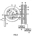
- FIGS. 1 and 2 are a sectional view and a plan view, respectively, schematically showing the structure of a liquid processing apparatus according to an embodiment of the present invention.
- This liquid processing apparatus 100 includes a wafer holding member 1 for rotatably holding a target substrate or wafer W with an oxide film formed thereon.
- the wafer holding member 1 is rotatable by a rotary motor 2.
- a cup 3 is disposed to surround the wafer W placed on the wafer holding member 1.
- the liquid processing apparatus 100 further includes a liquid supply mechanism 4 for supplying a dissolvent solution and purified water onto the wafer W, and a film thickness sensor 5 for measuring the thickness of the oxide film on the wafer W.
- the wafer holding member 1 includes a rotary plate 11 directly connected to the shaft 2a of the rotary motor 2.
- the rotary plate 11 is provided with three support pins 12a for supporting the wafer W and three hold pins 12b for holding the wafer W, which are attached to the peripheral portion of the rotary plate 11.
- the support pins 12a are utilized for this transfer.
- the hold pins 12b are rotatable in a direction indicated with an arrow A between an outer retreat position and a hold position for holding the wafer W, so that the hold pins 12b do not obstruct operations for transferring the wafer W between a transfer arm (not shown) and the wafer holding member 1.
- the hold pins 12b are set in the retreat position when the support pins 12a receive the wafer W, and then the hold pins 12b are rotated to the hold position, thereby holding the wafer W.
- the wafer holding member 1 is movable up and down by an elevating mechanism (not shown).
- the liquid supply mechanism 4 includes a first liquid delivery nozzle 21 and a second liquid delivery nozzle 22, each of which is movable for scanning between the center and peripheral edge of the wafer W.
- Each of the first and second liquid delivery nozzles 21 and 22 is arranged to selectively deliver diluted hydrofluoric acid (DHF) used as a process liquid for performing a dissolving process, and purified water used as a rinsing liquid.
- DHF diluted hydrofluoric acid
- the first liquid delivery nozzle 21 is connected to a first liquid supply line 23.
- the first liquid supply line 23 is connected to a diluted hydrofluoric acid supply line 26 and a purified water supply line 27 respectively through valves 24 and 25.
- diluted hydrofluoric acid used as a dissolvent solution and purified water used as a rinsing liquid can be delivered through the first liquid delivery nozzle 21 onto the surface of the wafer W.
- switching between the diluted hydrofluoric acid and purified water is performed by turning on/off the valves 24 and 25.
- the second liquid delivery nozzle 22 is connected to a second liquid supply line 28.
- the second liquid supply line 28 is connected to a diluted hydrofluoric acid supply line 31 and a purified water supply line 32 respectively through valves 29 and 30.
- diluted hydrofluoric acid used as a dissolvent solution and purified water used as a rinsing liquid can be delivered through the second liquid delivery nozzle 22 onto the surface of the wafer W, as in the first liquid delivery nozzle 21.
- switching between the diluted hydrofluoric acid and purified water is performed by turning on/off the valves 29 and 30.
- the diluted hydrofluoric acid supply lines 26 and 31 are connected to a liquid supply pump and a flow rate control unit (not shown).
- the purified water supply lines 27 and 32 are connected to a liquid supply pump and a flow rate control unit (not shown).
- the first liquid delivery nozzle 21 is designed to have a smaller diameter and thus provide a smaller delivery flow rate, as compared to the second liquid delivery nozzle 22.
- the first liquid delivery nozzle 21 has an inner diameter 0.5 mm ⁇ and provides a flow rate of 50 mL/min.
- the second liquid delivery nozzle 22 has an inner diameter 4 mm ⁇ and provides a flow rate of 500 mL/min.
- the first liquid delivery nozzle 21 preferably has a diameter of 0.2 to 2 mm, and preferably provides a delivery flow rate of 20 to 200 mL/min.
- the second liquid delivery nozzle 22 preferably has a diameter of 3 to 5 mm, and preferably provides a delivery flow rate of 300 to 2,000 mL/min. Further, as shown in FIG.
- the first liquid delivery nozzle 21 is inclined to deliver a process liquid in the rotational direction of the wafer W.
- This inclination angle is preferably set to be 15 to 75°, such as 30°.
- the second liquid delivery nozzle 22 is set in a vertical state as in the conventional nozzle, but may be set in an inclined state.
- the first liquid delivery nozzle 21 Since the first liquid delivery nozzle 21 has a smaller diameter and delivers a liquid at a smaller flow rate, it is possible to accurately control the liquid supply point and to decrease the liquid consumption. Further, since the first liquid delivery nozzle 21 is inclined to deliver a liquid in the rotational direction of the wafer W, the relative liquid velocity is decreased, thereby suppressing liquid flicks and/or liquid spread.
- the first liquid delivery nozzle 21 is held by a first nozzle holder 21a attached to a first nozzle arm 41.
- the first nozzle arm 41 is linearly movable between the center and peripheral edge of the wafer W by a ball screw mechanism 43.
- the ball screw mechanism 43 includes a ball screw 45 extending in the traveling direction of the first nozzle arm 41, and a guide rail 46 disposed in parallel with the ball screw 45.
- the first nozzle arm 41 is attached to a traveling member 47, which is screwed on the ball screw 45 and is slidably fitted on the guide rail 46.
- a driving mechanism 48 is disposed to rotate the ball screw 45, thereby linearly moving the traveling member 47.
- the second liquid delivery nozzle 22 is held by a second nozzle holder 22a attached to a second nozzle arm 42.
- the second nozzle arm 42 is linearly movable between the center and peripheral edge of the wafer W by a ball screw mechanism 44.
- the ball screw mechanism 44 includes a ball screw 49 extending in the traveling direction of the second nozzle arm 42, and a guide rail 50 disposed in parallel with the ball screw 49.
- the second nozzle arm 42 is attached to a traveling member 51, which is screwed on the ball screw 49 and is slidably fitted on the guide rail 50.
- a driving mechanism 52 is disposed to rotate the ball screw 49, thereby linearly moving the traveling member 51.
- the first and second liquid delivery nozzles 21 and 22 may be moved by a mechanism other than the ball screw mechanism. For example, a belt driving mechanism or cylinder mechanism may be used for this purpose.
- the cup 3 is configured to receive the process liquid or rinsing liquid separated from the wafer W by a centrifugal force during a process, and to drain it out of the apparatus.
- the cup 3 is provided with an exhaust passage 3a and two drain tubes 3b and 3c disposed at the bottom.
- the exhaust passage 3a is connected to the suction side of a gas exhaust pump (not shown).
- the cup 3 is movable up and down by an elevating mechanism (not shown).
- the film thickness sensor 5 is arranged to detect the thickness of an oxide film formed on the wafer W, without coming into contact with the wafer W.
- the film thickness sensor 5 is formed of an optical type thickness-meter or ellipsometer.
- the film thickness sensor 5 is attached to the distal end of an arm 55, which is linearly movable by a cylinder mechanism 56. Accordingly, the film thickness sensor 5 can be set at any position above the wafer W between the center and peripheral edge of the wafer W.
- the cylinder mechanism 56 comprises a cylinder 57 with a piston 58 movable outward and inward relative to the cylinder 57.
- the arm 55 is attached to a traveling member 60 fixed at the distal end of the piston 58.
- Each of the components in the liquid processing apparatus 100 is connected to and controlled by a controller 101 comprising a micro-processor (computer).
- the controller 101 is connected to a user interface 102, which includes, e.g., a keyboard and a display, wherein the keyboard is used for a process operator to input commands for operating the components in the liquid processing apparatus 100, and the display is used for showing visualized images of the operational status of the components in the liquid processing apparatus 100.
- the controller 101 is connected to the storage portion 103, which stores recipes with control programs and process condition data recorded therein, for realizing various processes performed in the liquid processing apparatus 100 under the control of the controller 101, and also stores other data necessary for the other control.
- a required recipe is retrieved from the storage portion 103 and executed by the controller 101 in accordance with an instruction or the like input through the user interface 102. Consequently, each of various predetermined processes is performed in the liquid processing apparatus 100 under the control of the controller 101.
- a recipe may be stored in a readable storage medium, such as a CD-ROM, hard disk, flexible disk, or nonvolatile memory. Further, a recipe may be utilized on-line, while it is transmitted from a suitable apparatus through, e.g., a dedicated line, as needed.
- the controller 101 is arranged to receive detection data (signals) detected by the film thickness sensor 5.
- the detection data is processed by an arithmetic comparison operation with reference to etching rate data (preset etching rates) of an oxide film obtained by, e.g., an experiment in advance.
- the result of this process is used to control the rotation number of the wafer W, the scanning velocity of a nozzle in supplying the process liquid, and the flow rates of the process liquid and purified water used as a rinsing liquid.
- the type of an oxide film 110, the composition of the process liquid, and the relationship between the temperature and etching rate are stored in the storage portion 103 in advance. Then, a wafer W with an oxide film formed on its surface is transferred by a transfer arm (not shown) onto the support pins 12a of the wafer holding member 1. Thereafter, the wafer W is held by the hold pins 12b. In this state, the film thickness is measured by the film thickness sensor 5 at a plurality of points between the center and peripheral edge of the wafer W to obtain a profile of the film thickness.
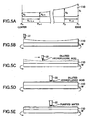
- the etching process (dissolving process) is performed in accordance with the steps shown in FIGS. 5A to 5E .
- traveling velocities (v1,2 to vn-1,n) of the first liquid delivery nozzle 21 between the respective points are calculated to perform planarization by etching with etching amounts X1 to Xn. This calculation can be performed by a method disclosed in paragraph 5, line 31 to paragraph 6, line 52 in US. Pat. Pub. No. 6,096,233 .
- the first liquid delivery nozzle 21 is set at a position above the end of the wafer W.
- the first liquid delivery nozzle 21 is moved for scanning toward the center with the velocities obtained as described above.
- a solution of diluted hydrofluoric acid is delivered from the first liquid delivery nozzle 21 to etch (dissolve) the oxide film, thereby planarizing the oxide film.
- the etching amount is preferably set to be the minimum amount necessary for the planarization.
- the rotation number of the wafer W is preferably set to be 100 to 1,000 rpm. The wafer W is kept rotated in a series of steps from this step to the subsequent steps.
- the first liquid delivery nozzle 21 is retreated, and the second liquid delivery nozzle 22 is set at a position above the center of the wafer W.
- a solution of diluted hydrofluoric acid is supplied from the second liquid delivery nozzle 22 to the entire surface of the wafer W. Consequently, etching is uniformly performed all over the wafer W, so that the oxide film 110 is processed to have a predetermined uniform thickness.
- the supply of diluted hydrofluoric acid from the second liquid delivery nozzle 22 is stopped. Further, as shown in FIG. 5E , purified water used as a rinsing liquid is supplied from the second liquid delivery nozzle 22 to terminate the etching.
- the oxide film 110 is planarized to have a predetermined thickness.
- the first liquid delivery nozzle 21 since the first liquid delivery nozzle 21 has a smaller diameter and delivers a liquid at a smaller flow rate, it is possible to accurately control the liquid supply point, when diluted hydrofluoric acid used as a process liquid is delivered to perform etching. Consequently, in spite of the presence of the support pins 12a and hold pins 12b serving as a wafer chuck, the thickness of the oxide film 110 can be accurately controlled at the peripheral portion of the wafer W. Further, since such a nozzle having a smaller diameter is used, the consumption of diluted hydrofluoric acid used as a process liquid can be decreased. Furthermore, since the first liquid delivery nozzle 21 is inclined to deliver a liquid in the rotational direction of the wafer W, the relative liquid velocity is decreased, thereby suppressing liquid flicks and/or liquid spread, and thus minimizing undesirable etching.
- the second liquid delivery nozzle 22 having a larger diameter and providing a larger flow rate is used.
- the second liquid delivery nozzle 22 is set at a position above the center of the wafer W and is used to supply the process liquid all over the wafer W to promote the etching. Consequently, it is possible to etch the oxide film at a high rate, thereby minimizing decrease in throughput.
- the first liquid delivery nozzle 21 when the process liquid is delivered, the first liquid delivery nozzle 21 is moved for scanning from the peripheral edge of the wafer W toward the center, while the wafer W is rotated. In reverse, when the process liquid is delivered, the first liquid delivery nozzle 21 may be moved for scanning from the center of the wafer W toward the peripheral edge, while the wafer W is rotated. Also in this case, traveling velocities of the first liquid delivery nozzle 21 between the respective film thickness detection points are calculated. This calculation can be performed by a method disclosed in paragraph 8, line 32 to paragraph 9, line 57 in US. Pat. Pub. No. 6,096,233 . This latter example provides the same effect as that of the former example.
- the film thickness is measured by the film thickness sensor 5 at a plurality of points between the center and peripheral edge of the wafer W, to obtain a profile of the film thickness.
- the etching process is performed in accordance with the steps shown in FIGS. 7A to 7E .
- traveling velocities (v1,2' to vn-1,n') of the first liquid delivery nozzle 21 between the respective points are calculated to perform planarization by etching with etching amounts X1 to Xn.
- the traveling velocities thus calculated are used in the purified water rinsing step, because the etching is first uniformly performed all over the film, and is then performed by use of differences in timing for supplying purified water used as a rinsing liquid. This calculation can be performed by a method based on the corresponding method disclosed in US. Pat. Pub. No. 6,096,233 .
- the second liquid delivery nozzle 22 is set at a position above the center of the wafer W.
- a solution of diluted hydrofluoric acid is supplied from the second liquid delivery nozzle 22 onto the wafer W to uniformly etch the oxide film 110.
- the second liquid delivery nozzle 22 is retreated, and the first liquid delivery nozzle 21 is set at a position above the end of the wafer W.
- FIG. 7D while the wafer W is rotated, the first liquid delivery nozzle 21 is moved for scanning toward the center with the velocities obtained as described above.
- purified water used as a rinsing liquid is delivered from the first liquid delivery nozzle 21 to sequentially stop the etching.
- the scanning velocity of the first liquid delivery nozzle 21 is suitably controlled to planarize the oxide film, so that the oxide film 110 is processed to have a uniform thickness.
- the etching is controlled to stop at a predetermined position of the oxide film 110 by the scanning of purified water provided by the first liquid delivery nozzle 21.
- the supply of purified water from the first liquid delivery nozzle 21 is stopped, and the first liquid delivery nozzle 21 is retreated.
- the second liquid delivery nozzle 22 is set at a position above the center of the wafer W. In this state, purified water used as a rinsing liquid is supplied from the second liquid delivery nozzle 22 to completely terminate the etching all over the wafer W.
- the oxide film 110 is planarized to have a predetermined thickness.
- the second liquid delivery nozzle 22 having a larger diameter and providing a larger flow rate is used to etch the oxide film 110 by a certain depth, while maintaining the cone-shaped projection profile.
- the first liquid delivery nozzle 21 having a smaller diameter and providing a smaller flow rate is used to stop the etching sequentially from a position corresponding to the end of the wafer W. Consequently, it is possible to accurately control the liquid supply point, and thus to accurately control the thickness of the oxide film 110 at the peripheral portion of the wafer W, in spite of the presence of the support pins 12a and hold pins 12b serving as a wafer chuck. Further, since such a nozzle having a smaller diameter is used, the consumption of purified water can be decreased.
- the first liquid delivery nozzle 21 is inclined to deliver a liquid in the rotational direction of the wafer W, the relative liquid velocity is decreased, thereby suppressing flicks and/or spread of purified water, and thus minimizing deterioration in the uniformity of etching due to uneven etching stoppage.
- the present invention is not limited to the embodiment described above, and it may be modified in various manners without departing from the spirit or scope of the present invention.
- the first liquid delivery nozzle 21 and second liquid delivery nozzle 22 are separately disposed, but these nozzles may be integratedly disposed in one nozzle holder 80, as shown in FIG. 8 .
- additional nozzle may be used for delivering a liquid or gas other than the film dissolving process liquid and rinsing liquid.
- an oxide film is a target film for a dissolving process (etching), but another film, such as a nitride film or metal film, may be processed in the same way.
- the process liquid is exemplified by diluted hydrofluoric acid, but another liquid may be used as long as it can be used for a dissolving process.
- the apparatus described above is provided with a film thickness sensor disposed therein, but the thickness of a film may be measured outside the apparatus and then stored in the storage portion 103. Further, the film thickness sensor is not indispensable, and a dissolving process may be performed in accordance with empirical values conventionally known.
- the target object is exemplified by a semiconductor wafer, but it may be another substrate, such as a substrate for flat panel display devices (FPD), a representative of which is a glass substrate for liquid crystal display devices (LCD).
- FPD flat panel display devices
- LCD liquid crystal display devices
Landscapes
- Engineering & Computer Science (AREA)
- Computer Hardware Design (AREA)
- Power Engineering (AREA)
- Condensed Matter Physics & Semiconductors (AREA)
- Microelectronics & Electronic Packaging (AREA)
- General Physics & Mathematics (AREA)
- Manufacturing & Machinery (AREA)
- Physics & Mathematics (AREA)
- Chemical & Material Sciences (AREA)
- General Chemical & Material Sciences (AREA)
- Chemical Kinetics & Catalysis (AREA)
- Organic Chemistry (AREA)
- Metallurgy (AREA)
- Mechanical Engineering (AREA)
- Materials Engineering (AREA)
- Cleaning Or Drying Semiconductors (AREA)
- Weting (AREA)
- Application Of Or Painting With Fluid Materials (AREA)
- Electrical Discharge Machining, Electrochemical Machining, And Combined Machining (AREA)
Applications Claiming Priority (1)
| Application Number | Priority Date | Filing Date | Title |
|---|---|---|---|
| JP2006089285A JP4708243B2 (ja) | 2006-03-28 | 2006-03-28 | 液処理装置および液処理方法ならびにコンピュータ読取可能な記憶媒体 |
Publications (3)
| Publication Number | Publication Date |
|---|---|
| EP1840942A2 EP1840942A2 (en) | 2007-10-03 |
| EP1840942A3 EP1840942A3 (en) | 2007-11-28 |
| EP1840942B1 true EP1840942B1 (en) | 2010-04-28 |
Family
ID=38255145
Family Applications (1)
| Application Number | Title | Priority Date | Filing Date |
|---|---|---|---|
| EP07006250A Not-in-force EP1840942B1 (en) | 2006-03-28 | 2007-03-27 | Liquid processing apparatus and liquid processing method |
Country Status (8)
| Country | Link |
|---|---|
| US (1) | US8043467B2 (enExample) |
| EP (1) | EP1840942B1 (enExample) |
| JP (1) | JP4708243B2 (enExample) |
| KR (1) | KR101098123B1 (enExample) |
| AT (1) | ATE466376T1 (enExample) |
| DE (1) | DE602007006089D1 (enExample) |
| SG (1) | SG136093A1 (enExample) |
| TW (1) | TW200802562A (enExample) |
Families Citing this family (29)
| Publication number | Priority date | Publication date | Assignee | Title |
|---|---|---|---|---|
| KR20080082010A (ko) * | 2006-01-31 | 2008-09-10 | 가부시키가이샤 섬코 | 웨이퍼의 매엽식 식각 방법 |
| JP4708243B2 (ja) * | 2006-03-28 | 2011-06-22 | 東京エレクトロン株式会社 | 液処理装置および液処理方法ならびにコンピュータ読取可能な記憶媒体 |
| JP2009105353A (ja) * | 2007-10-26 | 2009-05-14 | Renesas Technology Corp | 半導体装置の製造方法 |
| JP5026356B2 (ja) * | 2008-06-26 | 2012-09-12 | Sumco Techxiv株式会社 | 拡散ウェーハの製造方法 |
| JP5615650B2 (ja) | 2010-09-28 | 2014-10-29 | 大日本スクリーン製造株式会社 | 基板処理方法および基板処理装置 |
| JP5693439B2 (ja) * | 2011-12-16 | 2015-04-01 | 東京エレクトロン株式会社 | 基板処理装置、基板処理方法および記憶媒体 |
| KR102023623B1 (ko) * | 2012-07-03 | 2019-09-23 | 삼성전자 주식회사 | 반도체 소자 형성 방법 |
| JP5835188B2 (ja) * | 2012-11-06 | 2015-12-24 | 東京エレクトロン株式会社 | 基板周縁部の塗布膜除去方法、基板処理装置及び記憶媒体 |
| US20140261572A1 (en) * | 2013-03-15 | 2014-09-18 | Dainippon Screen Mfg.Co., Ltd. | Substrate treatment apparatus and substrate treatment method |
| JP6106519B2 (ja) * | 2013-05-09 | 2017-04-05 | 東京エレクトロン株式会社 | 基板処理方法、プログラム、制御装置、成膜装置及び基板処理システム |
| US9079210B2 (en) * | 2013-07-22 | 2015-07-14 | Infineon Technologies Ag | Methods for etching a workpiece, an apparatus configured to etch a workpiece, and a non-transitory computer readable medium |
| KR102121238B1 (ko) * | 2013-11-25 | 2020-06-10 | 세메스 주식회사 | 기판 처리 장치 및 기판 처리 방법 |
| JP6064875B2 (ja) * | 2013-11-25 | 2017-01-25 | 東京エレクトロン株式会社 | 液処理装置、液処理方法及び記憶媒体 |
| JP6163434B2 (ja) | 2014-01-16 | 2017-07-12 | 株式会社東芝 | 薬液処理装置及び薬液処理方法 |
| KR20160045299A (ko) | 2014-10-17 | 2016-04-27 | 도쿄엘렉트론가부시키가이샤 | 기판 처리 장치, 연계 처리 시스템 및 기판 처리 방법 |
| KR102276869B1 (ko) * | 2016-06-30 | 2021-07-14 | 어플라이드 머티어리얼스, 인코포레이티드 | 화학적 기계적 연마 자동화된 레시피 생성 |
| JP6815799B2 (ja) * | 2016-09-13 | 2021-01-20 | 東京エレクトロン株式会社 | 基板処理装置及び基板処理方法 |
| TW201828356A (zh) * | 2016-10-26 | 2018-08-01 | 日商東京威力科創股份有限公司 | 液體處理方法及液體處理裝置 |
| JP6923344B2 (ja) | 2017-04-13 | 2021-08-18 | 株式会社Screenホールディングス | 周縁処理装置および周縁処理方法 |
| CN112514035B (zh) * | 2018-07-26 | 2024-07-05 | 东京毅力科创株式会社 | 基板处理系统和基板处理方法 |
| JP7141892B2 (ja) * | 2018-09-03 | 2022-09-26 | 株式会社プレテック | エッチング装置及びエッチング方法 |
| JP7037459B2 (ja) * | 2018-09-10 | 2022-03-16 | キオクシア株式会社 | 半導体製造装置および半導体装置の製造方法 |
| KR20200075531A (ko) * | 2018-12-18 | 2020-06-26 | 삼성전자주식회사 | 기판 처리 장치 |
| CN112439582A (zh) * | 2019-08-30 | 2021-03-05 | 长鑫存储技术有限公司 | 喷淋装置、半导体处理设备以及喷淋反应物的方法 |
| US12387939B2 (en) * | 2019-12-16 | 2025-08-12 | Tokyo Electron Limited | Substrate processing method |
| TW202147481A (zh) * | 2020-01-23 | 2021-12-16 | 日商東京威力科創股份有限公司 | 基板處理裝置、基板處理方法及藥液 |
| JP7453020B2 (ja) * | 2020-03-06 | 2024-03-19 | 株式会社Screenホールディングス | 基板処理方法 |
| JP7486372B2 (ja) * | 2020-07-29 | 2024-05-17 | 東京エレクトロン株式会社 | 基板処理装置、及び基板処理方法 |
| JP7505439B2 (ja) * | 2021-04-12 | 2024-06-25 | 三菱電機株式会社 | 半導体製造装置および半導体装置の製造方法 |
Family Cites Families (11)
| Publication number | Priority date | Publication date | Assignee | Title |
|---|---|---|---|---|
| US5499733A (en) | 1992-09-17 | 1996-03-19 | Luxtron Corporation | Optical techniques of measuring endpoint during the processing of material layers in an optically hostile environment |
| JP3194037B2 (ja) * | 1996-09-24 | 2001-07-30 | 東京エレクトロン株式会社 | 枚葉回転処理方法及びその装置 |
| TW346649B (en) | 1996-09-24 | 1998-12-01 | Tokyo Electron Co Ltd | Method for wet etching a film |
| JP3395696B2 (ja) * | 1999-03-15 | 2003-04-14 | 日本電気株式会社 | ウェハ処理装置およびウェハ処理方法 |
| JP2001319919A (ja) * | 2000-05-08 | 2001-11-16 | Tokyo Electron Ltd | 半導体装置の製造方法及び処理装置 |
| JP4083016B2 (ja) * | 2001-02-07 | 2008-04-30 | 東京エレクトロン株式会社 | 無電解メッキ処理方法および無電解メッキ処理装置 |
| US6884294B2 (en) * | 2001-04-16 | 2005-04-26 | Tokyo Electron Limited | Coating film forming method and apparatus |
| US6770565B2 (en) | 2002-01-08 | 2004-08-03 | Applied Materials Inc. | System for planarizing metal conductive layers |
| JP2004006672A (ja) * | 2002-04-19 | 2004-01-08 | Dainippon Screen Mfg Co Ltd | 基板処理方法および基板処理装置 |
| JP4607755B2 (ja) * | 2005-12-19 | 2011-01-05 | 東京エレクトロン株式会社 | 基板洗浄方法、基板洗浄装置、制御プログラム、およびコンピュータ読取可能な記憶媒体 |
| JP4708243B2 (ja) * | 2006-03-28 | 2011-06-22 | 東京エレクトロン株式会社 | 液処理装置および液処理方法ならびにコンピュータ読取可能な記憶媒体 |
-
2006
- 2006-03-28 JP JP2006089285A patent/JP4708243B2/ja active Active
-
2007
- 2007-03-27 SG SG200702123-1A patent/SG136093A1/en unknown
- 2007-03-27 DE DE602007006089T patent/DE602007006089D1/de active Active
- 2007-03-27 US US11/727,656 patent/US8043467B2/en not_active Expired - Fee Related
- 2007-03-27 KR KR1020070029758A patent/KR101098123B1/ko active Active
- 2007-03-27 AT AT07006250T patent/ATE466376T1/de active
- 2007-03-27 EP EP07006250A patent/EP1840942B1/en not_active Not-in-force
- 2007-03-27 TW TW096110637A patent/TW200802562A/zh not_active IP Right Cessation
Also Published As
| Publication number | Publication date |
|---|---|
| EP1840942A2 (en) | 2007-10-03 |
| ATE466376T1 (de) | 2010-05-15 |
| US20070231483A1 (en) | 2007-10-04 |
| DE602007006089D1 (de) | 2010-06-10 |
| TWI362695B (enExample) | 2012-04-21 |
| KR101098123B1 (ko) | 2011-12-26 |
| US8043467B2 (en) | 2011-10-25 |
| JP4708243B2 (ja) | 2011-06-22 |
| EP1840942A3 (en) | 2007-11-28 |
| SG136093A1 (en) | 2007-10-29 |
| KR20070097345A (ko) | 2007-10-04 |
| TW200802562A (en) | 2008-01-01 |
| JP2007266302A (ja) | 2007-10-11 |
Similar Documents
| Publication | Publication Date | Title |
|---|---|---|
| EP1840942B1 (en) | Liquid processing apparatus and liquid processing method | |
| US7252097B2 (en) | System and method for integrating in-situ metrology within a wafer process | |
| JP6183705B2 (ja) | 基板処理方法および基板処理装置 | |
| US10163664B2 (en) | Substrate cleaning apparatus and substrate cleaning method | |
| US20050058775A1 (en) | Method and apparatus for forming coating film | |
| US11534886B2 (en) | Polishing device, polishing head, polishing method, and method of manufacturing semiconductor device | |
| TW201828356A (zh) | 液體處理方法及液體處理裝置 | |
| KR102301802B1 (ko) | 기판 처리 방법 및 기판 처리 장치 | |
| JP7376317B2 (ja) | 基板処理方法 | |
| CN101371340B (zh) | 晶片的表面平滑方法和其装置 | |
| KR102387540B1 (ko) | 기판 세정 장치 및 기판 세정 방법 | |
| JPH11251289A (ja) | 基板処理装置および基板処理方法 | |
| KR102714577B1 (ko) | 기판 처리 방법 | |
| TWI806604B (zh) | 單晶圓處理設備、單晶圓處理方法和單晶圓處理系統 | |
| KR102857077B1 (ko) | 기판 처리 장치 및 기판 처리 방법 | |
| JP2010016157A (ja) | 基板洗浄装置 | |
| CN101263584A (zh) | 处理衬底的方法和设备 |
Legal Events
| Date | Code | Title | Description |
|---|---|---|---|
| PUAI | Public reference made under article 153(3) epc to a published international application that has entered the european phase |
Free format text: ORIGINAL CODE: 0009012 |
|
| AK | Designated contracting states |
Kind code of ref document: A2 Designated state(s): AT BE BG CH CY CZ DE DK EE ES FI FR GB GR HU IE IS IT LI LT LU LV MC MT NL PL PT RO SE SI SK TR |
|
| AX | Request for extension of the european patent |
Extension state: AL BA HR MK YU |
|
| PUAL | Search report despatched |
Free format text: ORIGINAL CODE: 0009013 |
|
| AK | Designated contracting states |
Kind code of ref document: A3 Designated state(s): AT BE BG CH CY CZ DE DK EE ES FI FR GB GR HU IE IS IT LI LT LU LV MC MT NL PL PT RO SE SI SK TR |
|
| AX | Request for extension of the european patent |
Extension state: AL BA HR MK YU |
|
| 17P | Request for examination filed |
Effective date: 20080527 |
|
| 17Q | First examination report despatched |
Effective date: 20080704 |
|
| AKX | Designation fees paid |
Designated state(s): AT BE DE FR |
|
| GRAP | Despatch of communication of intention to grant a patent |
Free format text: ORIGINAL CODE: EPIDOSNIGR1 |
|
| GRAS | Grant fee paid |
Free format text: ORIGINAL CODE: EPIDOSNIGR3 |
|
| GRAA | (expected) grant |
Free format text: ORIGINAL CODE: 0009210 |
|
| AK | Designated contracting states |
Kind code of ref document: B1 Designated state(s): AT BE DE FR |
|
| REF | Corresponds to: |
Ref document number: 602007006089 Country of ref document: DE Date of ref document: 20100610 Kind code of ref document: P |
|
| PLBE | No opposition filed within time limit |
Free format text: ORIGINAL CODE: 0009261 |
|
| STAA | Information on the status of an ep patent application or granted ep patent |
Free format text: STATUS: NO OPPOSITION FILED WITHIN TIME LIMIT |
|
| 26N | No opposition filed |
Effective date: 20110131 |
|
| PGFP | Annual fee paid to national office [announced via postgrant information from national office to epo] |
Ref country code: FR Payment date: 20110317 Year of fee payment: 5 |
|
| REG | Reference to a national code |
Ref country code: FR Ref legal event code: ST Effective date: 20121130 |
|
| PG25 | Lapsed in a contracting state [announced via postgrant information from national office to epo] |
Ref country code: FR Free format text: LAPSE BECAUSE OF NON-PAYMENT OF DUE FEES Effective date: 20120402 |
|
| PGFP | Annual fee paid to national office [announced via postgrant information from national office to epo] |
Ref country code: DE Payment date: 20130320 Year of fee payment: 7 |
|
| PGFP | Annual fee paid to national office [announced via postgrant information from national office to epo] |
Ref country code: BE Payment date: 20130312 Year of fee payment: 7 |
|
| REG | Reference to a national code |
Ref country code: DE Ref legal event code: R119 Ref document number: 602007006089 Country of ref document: DE |
|
| REG | Reference to a national code |
Ref country code: DE Ref legal event code: R119 Ref document number: 602007006089 Country of ref document: DE Effective date: 20141001 |
|
| PG25 | Lapsed in a contracting state [announced via postgrant information from national office to epo] |
Ref country code: DE Free format text: LAPSE BECAUSE OF NON-PAYMENT OF DUE FEES Effective date: 20141001 |
|
| PGFP | Annual fee paid to national office [announced via postgrant information from national office to epo] |
Ref country code: AT Payment date: 20150225 Year of fee payment: 9 |
|
| REG | Reference to a national code |
Ref country code: AT Ref legal event code: MM01 Ref document number: 466376 Country of ref document: AT Kind code of ref document: T Effective date: 20160327 |
|
| PG25 | Lapsed in a contracting state [announced via postgrant information from national office to epo] |
Ref country code: AT Free format text: LAPSE BECAUSE OF NON-PAYMENT OF DUE FEES Effective date: 20160327 |
|
| PG25 | Lapsed in a contracting state [announced via postgrant information from national office to epo] |
Ref country code: BE Free format text: LAPSE BECAUSE OF NON-PAYMENT OF DUE FEES Effective date: 20140331 |