EP1840326A1 - Spiralfluidmaschine - Google Patents
Spiralfluidmaschine Download PDFInfo
- Publication number
- EP1840326A1 EP1840326A1 EP07104808A EP07104808A EP1840326A1 EP 1840326 A1 EP1840326 A1 EP 1840326A1 EP 07104808 A EP07104808 A EP 07104808A EP 07104808 A EP07104808 A EP 07104808A EP 1840326 A1 EP1840326 A1 EP 1840326A1
- Authority
- EP
- European Patent Office
- Prior art keywords
- driving shaft
- scroll
- fluid machine
- gap
- circumferential surface
- Prior art date
- Legal status (The legal status is an assumption and is not a legal conclusion. Google has not performed a legal analysis and makes no representation as to the accuracy of the status listed.)
- Withdrawn
Links
Images
Classifications
-
- F—MECHANICAL ENGINEERING; LIGHTING; HEATING; WEAPONS; BLASTING
- F01—MACHINES OR ENGINES IN GENERAL; ENGINE PLANTS IN GENERAL; STEAM ENGINES
- F01C—ROTARY-PISTON OR OSCILLATING-PISTON MACHINES OR ENGINES
- F01C1/00—Rotary-piston machines or engines
- F01C1/02—Rotary-piston machines or engines of arcuate-engagement type, i.e. with circular translatory movement of co-operating members, each member having the same number of teeth or tooth-equivalents
- F01C1/0207—Rotary-piston machines or engines of arcuate-engagement type, i.e. with circular translatory movement of co-operating members, each member having the same number of teeth or tooth-equivalents both members having co-operating elements in spiral form
- F01C1/0215—Rotary-piston machines or engines of arcuate-engagement type, i.e. with circular translatory movement of co-operating members, each member having the same number of teeth or tooth-equivalents both members having co-operating elements in spiral form where only one member is moving
- F01C1/0223—Rotary-piston machines or engines of arcuate-engagement type, i.e. with circular translatory movement of co-operating members, each member having the same number of teeth or tooth-equivalents both members having co-operating elements in spiral form where only one member is moving with symmetrical double wraps
-
- F—MECHANICAL ENGINEERING; LIGHTING; HEATING; WEAPONS; BLASTING
- F01—MACHINES OR ENGINES IN GENERAL; ENGINE PLANTS IN GENERAL; STEAM ENGINES
- F01C—ROTARY-PISTON OR OSCILLATING-PISTON MACHINES OR ENGINES
- F01C21/00—Component parts, details or accessories not provided for in groups F01C1/00 - F01C20/00
- F01C21/02—Arrangements of bearings
-
- F—MECHANICAL ENGINEERING; LIGHTING; HEATING; WEAPONS; BLASTING
- F01—MACHINES OR ENGINES IN GENERAL; ENGINE PLANTS IN GENERAL; STEAM ENGINES
- F01C—ROTARY-PISTON OR OSCILLATING-PISTON MACHINES OR ENGINES
- F01C21/00—Component parts, details or accessories not provided for in groups F01C1/00 - F01C20/00
- F01C21/06—Heating; Cooling; Heat insulation
-
- F—MECHANICAL ENGINEERING; LIGHTING; HEATING; WEAPONS; BLASTING
- F04—POSITIVE - DISPLACEMENT MACHINES FOR LIQUIDS; PUMPS FOR LIQUIDS OR ELASTIC FLUIDS
- F04C—ROTARY-PISTON, OR OSCILLATING-PISTON, POSITIVE-DISPLACEMENT MACHINES FOR LIQUIDS; ROTARY-PISTON, OR OSCILLATING-PISTON, POSITIVE-DISPLACEMENT PUMPS
- F04C29/00—Component parts, details or accessories of pumps or pumping installations, not provided for in groups F04C18/00 - F04C28/00
- F04C29/0042—Driving elements, brakes, couplings, transmissions specially adapted for pumps
- F04C29/005—Means for transmitting movement from the prime mover to driven parts of the pump, e.g. clutches, couplings, transmissions
- F04C29/0057—Means for transmitting movement from the prime mover to driven parts of the pump, e.g. clutches, couplings, transmissions for eccentric movement
-
- F—MECHANICAL ENGINEERING; LIGHTING; HEATING; WEAPONS; BLASTING
- F04—POSITIVE - DISPLACEMENT MACHINES FOR LIQUIDS; PUMPS FOR LIQUIDS OR ELASTIC FLUIDS
- F04C—ROTARY-PISTON, OR OSCILLATING-PISTON, POSITIVE-DISPLACEMENT MACHINES FOR LIQUIDS; ROTARY-PISTON, OR OSCILLATING-PISTON, POSITIVE-DISPLACEMENT PUMPS
- F04C18/00—Rotary-piston pumps specially adapted for elastic fluids
- F04C18/02—Rotary-piston pumps specially adapted for elastic fluids of arcuate-engagement type, i.e. with circular translatory movement of co-operating members, each member having the same number of teeth or tooth-equivalents
- F04C18/0207—Rotary-piston pumps specially adapted for elastic fluids of arcuate-engagement type, i.e. with circular translatory movement of co-operating members, each member having the same number of teeth or tooth-equivalents both members having co-operating elements in spiral form
- F04C18/0215—Rotary-piston pumps specially adapted for elastic fluids of arcuate-engagement type, i.e. with circular translatory movement of co-operating members, each member having the same number of teeth or tooth-equivalents both members having co-operating elements in spiral form where only one member is moving
- F04C18/0223—Rotary-piston pumps specially adapted for elastic fluids of arcuate-engagement type, i.e. with circular translatory movement of co-operating members, each member having the same number of teeth or tooth-equivalents both members having co-operating elements in spiral form where only one member is moving with symmetrical double wraps
-
- F—MECHANICAL ENGINEERING; LIGHTING; HEATING; WEAPONS; BLASTING
- F04—POSITIVE - DISPLACEMENT MACHINES FOR LIQUIDS; PUMPS FOR LIQUIDS OR ELASTIC FLUIDS
- F04C—ROTARY-PISTON, OR OSCILLATING-PISTON, POSITIVE-DISPLACEMENT MACHINES FOR LIQUIDS; ROTARY-PISTON, OR OSCILLATING-PISTON, POSITIVE-DISPLACEMENT PUMPS
- F04C29/00—Component parts, details or accessories of pumps or pumping installations, not provided for in groups F04C18/00 - F04C28/00
- F04C29/04—Heating; Cooling; Heat insulation
-
- F—MECHANICAL ENGINEERING; LIGHTING; HEATING; WEAPONS; BLASTING
- F16—ENGINEERING ELEMENTS AND UNITS; GENERAL MEASURES FOR PRODUCING AND MAINTAINING EFFECTIVE FUNCTIONING OF MACHINES OR INSTALLATIONS; THERMAL INSULATION IN GENERAL
- F16C—SHAFTS; FLEXIBLE SHAFTS; ELEMENTS OR CRANKSHAFT MECHANISMS; ROTARY BODIES OTHER THAN GEARING ELEMENTS; BEARINGS
- F16C2360/00—Engines or pumps
- F16C2360/42—Pumps with cylinders or pistons
Definitions
- the present invention relates to a scroll fluid machine such as a scroll vacuum pump or a scroll compressor.
- US6,109,897A discloses a scroll fluid machine that comprises a fixed scroll and an orbiting scroll rotatably mounted to an eccentric axial portion of a driving shaft, a cooling path extending through the driving shaft axially, a cooling gas being introduced in the cooling path to cool bearings and sealing members between the orbiting scroll and the driving shaft.
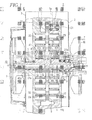
- Fig. 1 is a vertical sectional side view of an embodiment of a scroll fluid machine according to the present invention.
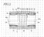
- Fig. 2 is an enlarged side view of the main part of the invention.
- a housing 1 comprises a rear casing 2 and a front cover 3. Close to the outer circumference, an intake port 1a is formed for sucking a gas into the housing 1, and close to the center, a discharge port (not shown) is formed for discharging compressed gas from the housing 1.
- the casing 2 and cover 3 have circular end plates 21,31 respectively, which has spiral or involute-curve fixed wraps 22,32 to constitute fixed scrolls 23,33. Between the fixed scrolls 23 and 33, an orbiting scroll 5 is rotatably mounted on an eccentric axial portion 41 of a driving shaft 4.
- the driving shaft 4 is connected at the rear end to a motor (not shown) as driving source and rotatably mounted in axial holes 21a,31a at the center of the fixed end plates 21,31 via bearings 6,7.
- the orbiting scroll 5 is rotatably mounted to the eccentric axial portion 41 of the driving shaft 4 in an axial hole 52 at the center and has orbiting wraps 51,51 engaging with fixed wraps 22,32 by 180 degrees, and is connected to the fixed end plate 21 with three known pin-crank-type self-rotation-preventing devices 8 equally spaced.
- the orbiting scroll 5 With rotation of the driving shaft 4 by the motor, the orbiting scroll 5 is revolved thereby allowing a compression chamber defined by the fixed wraps 22,32 and the orbiting wraps 51,51 to reduce in volume towards the center. A gas sucked through the intake port is gradually compressed and discharged from the discharge port in the middle.
- front and rear cooling fans 9,10 rotates with the driving shaft 4 to produce air flow in a centrifugal direction.
- front and rear bearings 11,12 are mounted to allow the driving shaft 4 to rotate smoothly with respect to the orbiting scroll 5.
- annular member 15 such as Cu, having thermal conductivity higher than the orbiting scroll 5 made of Al alloy, is fixed to rotate together with the orbiting scroll 5.
- the annular member 15 may be a bearing, and a gap between the outer circumferential surface of a spiral groove 44 and the inner circumferential surface of the annular member 15 is determined as close as possible.
- the first cooling path 42 allows a cooling gas to flow into a gap 16 between the outer circumferential surface of the eccentric axial portion 41 and the annular member 15 from the front end, and the second cooling path 43 allows the cooling gas to discharge from the gap 16 to outside through the rear end of the driving shaft 4.
- the first cooling path 43 comprises the first axial hole 42a which axially extends from the rear end of the driving shaft 4, and the first radial hole 42b which radially extends from the first axial hole 42a and opens to the outer circumferential surface of the eccentric axial portion 41.
- the second cooling path 43 comprises the second axial hole 43a which axially extends from the rear end of the driving shaft 4 to the middle of the eccentric axial portion 41, and the second radial hole 43b which radially extends from the second axial hole 43a and opens to the outer circumferential surface of the eccentric axial portion 41.
- the rear end of the second axial hole 43b of the second cooling path 43 is closed by a closing member 17, and a plurality of discharge holes 43c are radially formed close to the rear end of the second axial hole 43a.
- the first radial hole 42b and second radial hole 43b are disposed in the eccentric axial portion 41 axially apart from each other within the gap 16.
- a spiral groove 44 is formed and surrounded by the annular member 15.
- a thread of the spiral groove 44 is formed in a direction contrary to a rotational direction of the driving shaft 4 to act as forced convection generating portion.
- the spiral groove 44 With rotation of the driving shaft 4, the spiral groove 44 generates forced convection axially so that a cooling gas is sucked into the gap 16 through the first cooling path 42 and discharged from the discharge hole 43c through the second cooling path 43.
- the cooling gas is sucked from the front end of the first axial hole 42a and introduced into the gap 16 through the first radial hole 42b.
- the cooling gas introduced in the first cooling path 42 cools the front part of the driving shaft 4.
- the cooling gas introduced in the gap 16 directly cools the eccentric axial portion 41, the annular member 16, the front and rear bearings 11,12 and the sealing members 13,14, the gas is forwarded rearwards and discharged from the discharge hole 43c through the second axial hole 43a of the second cooling path 43.
- the cooling gas introduced in the second cooling path 43 cools the rear part of the driving shaft 4.
- the annular member 15 has thermal conductivity higher than the orbiting scroll 5. Thus, cooling in the gap 16 is efficiently transferred to the center of the orbiting scroll 5 which is effectively cooled, thereby improving durability of the front and rear bearings 11,12 and sealing members 13,14.
- the annular member 15 When the annular member 15 is a sliding bearing, the inner circumferential surface of the annular member 15 can be approached to the outer circumference of the spiral groove 44, so that the cooling gas is forwarded rearwards efficiently by flow of forced convection by a screw-pump action to enable efficient cooling.
- the embodiment relates to a both-side scroll fluid machine in which the both-side orbiting scroll 5 is disposed between the two fixed scrolls 23 and 33, but the present invention may apply to a one-side scroll fluid machine in which a one-side fixed scroll engages with a one-side orbiting scroll.
- a driving shaft has an eccentric axial portion around which an orbiting scroll revolves while the orbiting scroll engages with a fixed scroll.
- a cooling path extends through the driving shaft to a gap between the outer circumferential surface of the eccentric axial portion and the inner circumferential surface of an axial hole of the orbiting scroll.
- a cooling gas is introduced into the cooling path to cool bearings around the driving shaft.
- a forced convection generating portion is provided on the driving shaft for sucking the cooling gas into the gap and discharging the gas.
Applications Claiming Priority (1)
| Application Number | Priority Date | Filing Date | Title |
|---|---|---|---|
| JP2006084497A JP4837416B2 (ja) | 2006-03-27 | 2006-03-27 | スクロール流体機械 |
Publications (1)
| Publication Number | Publication Date |
|---|---|
| EP1840326A1 true EP1840326A1 (de) | 2007-10-03 |
Family
ID=38215154
Family Applications (1)
| Application Number | Title | Priority Date | Filing Date |
|---|---|---|---|
| EP07104808A Withdrawn EP1840326A1 (de) | 2006-03-27 | 2007-03-23 | Spiralfluidmaschine |
Country Status (4)
| Country | Link |
|---|---|
| US (1) | US7497673B2 (de) |
| EP (1) | EP1840326A1 (de) |
| JP (1) | JP4837416B2 (de) |
| CN (1) | CN100549421C (de) |
Cited By (2)
| Publication number | Priority date | Publication date | Assignee | Title |
|---|---|---|---|---|
| GB2544968A (en) * | 2015-11-26 | 2017-06-07 | Edwards Ltd | Dry vacuum scroll pump |
| WO2019145680A1 (en) * | 2018-01-29 | 2019-08-01 | Edwards Limited | Scroll vacuum pump |
Families Citing this family (7)
| Publication number | Priority date | Publication date | Assignee | Title |
|---|---|---|---|---|
| KR101300597B1 (ko) * | 2008-12-18 | 2013-08-28 | (주)리치스톤 | 스크롤 유체기계 |
| CN103291616A (zh) * | 2012-03-02 | 2013-09-11 | 日本株式会社富石 | 涡旋式流体机械 |
| JP5931563B2 (ja) * | 2012-04-25 | 2016-06-08 | アネスト岩田株式会社 | スクロール膨張機 |
| CN104314810A (zh) * | 2014-10-29 | 2015-01-28 | 王涛杰 | 水冷式无油涡旋压缩机 |
| CN104500395B (zh) * | 2014-12-12 | 2016-08-17 | 沙无埃 | 涡旋压缩机 |
| CN110159530B (zh) * | 2019-06-28 | 2020-09-18 | 珠海格力节能环保制冷技术研究中心有限公司 | 涡旋压缩机、车辆 |
| GB2589104A (en) * | 2019-11-19 | 2021-05-26 | Edwards Ltd | Scroll pump |
Citations (7)
| Publication number | Priority date | Publication date | Assignee | Title |
|---|---|---|---|---|
| SU953268A2 (ru) * | 1980-09-08 | 1982-08-23 | Омский политехнический институт | Ротор винтовой компрессорной машины |
| JPS57208319A (en) | 1981-06-18 | 1982-12-21 | Sony Corp | Ball-and-roller bearings |
| JP2001298018A (ja) * | 2000-04-18 | 2001-10-26 | Anest Iwata Corp | 半導体製造ラインにおける不純物排除方法、半導体製造システム及びそれらに使用可能なスクロール流体機械 |
| JP2001298081A (ja) | 2000-04-12 | 2001-10-26 | Nec Corp | 半導体装置及びその製造方法 |
| JP2002257064A (ja) * | 2001-02-28 | 2002-09-11 | Tokico Ltd | スクロール式流体機械 |
| JP2005233043A (ja) * | 2004-02-18 | 2005-09-02 | Toyota Industries Corp | スクロール型流体機械 |
| EP1626178A1 (de) * | 2004-08-09 | 2006-02-15 | Anest Iwata Corporation | Spiralvakuumpumpe |
Family Cites Families (5)
| Publication number | Priority date | Publication date | Assignee | Title |
|---|---|---|---|---|
| JPH084667A (ja) * | 1994-06-15 | 1996-01-09 | Toyota Autom Loom Works Ltd | スクロール型圧縮機 |
| US5551852A (en) * | 1994-07-29 | 1996-09-03 | Zexel Corporation | Scroll type compressor having a seal bearing unit |
| JP3423514B2 (ja) * | 1995-11-30 | 2003-07-07 | アネスト岩田株式会社 | スクロール流体機械 |
| JP4256197B2 (ja) * | 2003-04-11 | 2009-04-22 | アネスト岩田株式会社 | スクロール減圧機械 |
| US6953330B1 (en) * | 2004-08-02 | 2005-10-11 | Anest Iwata Corporation | Scroll vacuum pump |
-
2006
- 2006-03-27 JP JP2006084497A patent/JP4837416B2/ja not_active Expired - Fee Related
-
2007
- 2007-03-19 CN CNB2007100868527A patent/CN100549421C/zh not_active Expired - Fee Related
- 2007-03-23 EP EP07104808A patent/EP1840326A1/de not_active Withdrawn
- 2007-03-23 US US11/690,396 patent/US7497673B2/en not_active Expired - Fee Related
Patent Citations (7)
| Publication number | Priority date | Publication date | Assignee | Title |
|---|---|---|---|---|
| SU953268A2 (ru) * | 1980-09-08 | 1982-08-23 | Омский политехнический институт | Ротор винтовой компрессорной машины |
| JPS57208319A (en) | 1981-06-18 | 1982-12-21 | Sony Corp | Ball-and-roller bearings |
| JP2001298081A (ja) | 2000-04-12 | 2001-10-26 | Nec Corp | 半導体装置及びその製造方法 |
| JP2001298018A (ja) * | 2000-04-18 | 2001-10-26 | Anest Iwata Corp | 半導体製造ラインにおける不純物排除方法、半導体製造システム及びそれらに使用可能なスクロール流体機械 |
| JP2002257064A (ja) * | 2001-02-28 | 2002-09-11 | Tokico Ltd | スクロール式流体機械 |
| JP2005233043A (ja) * | 2004-02-18 | 2005-09-02 | Toyota Industries Corp | スクロール型流体機械 |
| EP1626178A1 (de) * | 2004-08-09 | 2006-02-15 | Anest Iwata Corporation | Spiralvakuumpumpe |
Non-Patent Citations (1)
| Title |
|---|
| DATABASE WPI Week 198326, Derwent World Patents Index; AN 1983-J7452K, XP002441645 * |
Cited By (2)
| Publication number | Priority date | Publication date | Assignee | Title |
|---|---|---|---|---|
| GB2544968A (en) * | 2015-11-26 | 2017-06-07 | Edwards Ltd | Dry vacuum scroll pump |
| WO2019145680A1 (en) * | 2018-01-29 | 2019-08-01 | Edwards Limited | Scroll vacuum pump |
Also Published As
| Publication number | Publication date |
|---|---|
| JP4837416B2 (ja) | 2011-12-14 |
| JP2007255393A (ja) | 2007-10-04 |
| CN101046203A (zh) | 2007-10-03 |
| CN100549421C (zh) | 2009-10-14 |
| US20070224069A1 (en) | 2007-09-27 |
| US7497673B2 (en) | 2009-03-03 |
Similar Documents
| Publication | Publication Date | Title |
|---|---|---|
| EP1840326A1 (de) | Spiralfluidmaschine | |
| EP1770243B1 (de) | Scrollmaschine | |
| JP7042265B2 (ja) | 分離された冷却気路を備えたターボ圧縮機 | |
| EP3401549B1 (de) | Turboverdichter | |
| JP2007120468A (ja) | スクロール式流体機械 | |
| JP5020628B2 (ja) | スクロール流体機械 | |
| EP1813813A2 (de) | Spiralfluidmaschine | |
| JP2014196688A (ja) | スクロール式流体機械 | |
| JP4822943B2 (ja) | 流体機械 | |
| JP2006307699A (ja) | 圧縮機 | |
| JP6633305B2 (ja) | スクロール圧縮機 | |
| JP6185297B2 (ja) | スクロール式流体機械 | |
| JP5328536B2 (ja) | スクロール圧縮機 | |
| JP5001334B2 (ja) | スクロール式流体機械 | |
| JP2015001176A (ja) | スクロール式流体機械 | |
| EP1707815B1 (de) | Spiralverdichter mit einem Schalldämpfer | |
| JP4754061B2 (ja) | スクロール型圧縮機 | |
| JP2008031976A (ja) | 電動圧縮機 | |
| JP2004116458A (ja) | スクロール型圧縮機 | |
| JPH0587285U (ja) | スクロール流体機械 | |
| JP3653128B2 (ja) | スクロール式流体機械 | |
| JP2005233043A (ja) | スクロール型流体機械 | |
| JP4935511B2 (ja) | スクロール圧縮機 | |
| JP2009293377A (ja) | スクロール流体機械 | |
| JP2007077959A (ja) | スクロール圧縮機 |
Legal Events
| Date | Code | Title | Description |
|---|---|---|---|
| PUAI | Public reference made under article 153(3) epc to a published international application that has entered the european phase |
Free format text: ORIGINAL CODE: 0009012 |
|
| 17P | Request for examination filed |
Effective date: 20070418 |
|
| AK | Designated contracting states |
Kind code of ref document: A1 Designated state(s): AT BE BG CH CY CZ DE DK EE ES FI FR GB GR HU IE IS IT LI LT LU LV MC MT NL PL PT RO SE SI SK TR |
|
| AX | Request for extension of the european patent |
Extension state: AL BA HR MK YU |
|
| 17Q | First examination report despatched |
Effective date: 20080115 |
|
| R17C | First examination report despatched (corrected) |
Effective date: 20080115 |
|
| AKX | Designation fees paid |
Designated state(s): DE FR GB |
|
| STAA | Information on the status of an ep patent application or granted ep patent |
Free format text: STATUS: THE APPLICATION IS DEEMED TO BE WITHDRAWN |
|
| 18D | Application deemed to be withdrawn |
Effective date: 20101001 |