EP1835164A2 - Véhicule ou centrale stationnaire doté(e) d'un moteur à combustion interne chargé comme arbre d'entraînement - Google Patents
Véhicule ou centrale stationnaire doté(e) d'un moteur à combustion interne chargé comme arbre d'entraînement Download PDFInfo
- Publication number
- EP1835164A2 EP1835164A2 EP07003700A EP07003700A EP1835164A2 EP 1835164 A2 EP1835164 A2 EP 1835164A2 EP 07003700 A EP07003700 A EP 07003700A EP 07003700 A EP07003700 A EP 07003700A EP 1835164 A2 EP1835164 A2 EP 1835164A2
- Authority
- EP
- European Patent Office
- Prior art keywords
- heat exchanger
- medium
- vehicle
- heat
- power plant
- Prior art date
- Legal status (The legal status is an assumption and is not a legal conclusion. Google has not performed a legal analysis and makes no representation as to the accuracy of the status listed.)
- Granted
Links
- 238000002485 combustion reaction Methods 0.000 title claims abstract description 27
- 238000009434 installation Methods 0.000 title description 2
- 230000005855 radiation Effects 0.000 claims abstract description 6
- 238000010438 heat treatment Methods 0.000 claims description 41
- 239000007788 liquid Substances 0.000 claims description 17
- 238000001816 cooling Methods 0.000 claims description 14
- 239000000498 cooling water Substances 0.000 claims description 11
- XLYOFNOQVPJJNP-UHFFFAOYSA-N water Substances O XLYOFNOQVPJJNP-UHFFFAOYSA-N 0.000 claims description 11
- 230000004913 activation Effects 0.000 claims description 6
- 239000002826 coolant Substances 0.000 claims description 6
- 230000002528 anti-freeze Effects 0.000 claims description 5
- 238000007710 freezing Methods 0.000 claims description 5
- 230000008014 freezing Effects 0.000 claims description 5
- 238000009835 boiling Methods 0.000 claims description 4
- 239000012530 fluid Substances 0.000 claims description 4
- 238000003860 storage Methods 0.000 claims description 4
- WTHDKMILWLGDKL-UHFFFAOYSA-N urea;hydrate Chemical compound O.NC(N)=O WTHDKMILWLGDKL-UHFFFAOYSA-N 0.000 claims description 4
- 238000004140 cleaning Methods 0.000 claims description 3
- 230000002776 aggregation Effects 0.000 claims description 2
- 238000004220 aggregation Methods 0.000 claims description 2
- 230000033228 biological regulation Effects 0.000 claims description 2
- 238000004891 communication Methods 0.000 claims description 2
- 230000008878 coupling Effects 0.000 claims description 2
- 238000010168 coupling process Methods 0.000 claims description 2
- 238000005859 coupling reaction Methods 0.000 claims description 2
- 230000009849 deactivation Effects 0.000 claims description 2
- 238000005338 heat storage Methods 0.000 claims description 2
- 239000007789 gas Substances 0.000 description 27
- QGZKDVFQNNGYKY-UHFFFAOYSA-N Ammonia Chemical compound N QGZKDVFQNNGYKY-UHFFFAOYSA-N 0.000 description 2
- 229910000831 Steel Inorganic materials 0.000 description 2
- 230000000694 effects Effects 0.000 description 2
- 230000017525 heat dissipation Effects 0.000 description 2
- 238000009413 insulation Methods 0.000 description 2
- 239000010959 steel Substances 0.000 description 2
- 238000010257 thawing Methods 0.000 description 2
- 238000010792 warming Methods 0.000 description 2
- 238000003466 welding Methods 0.000 description 2
- VHUUQVKOLVNVRT-UHFFFAOYSA-N Ammonium hydroxide Chemical compound [NH4+].[OH-] VHUUQVKOLVNVRT-UHFFFAOYSA-N 0.000 description 1
- 229910021529 ammonia Inorganic materials 0.000 description 1
- 235000011114 ammonium hydroxide Nutrition 0.000 description 1
- 239000003054 catalyst Substances 0.000 description 1
- 230000008859 change Effects 0.000 description 1
- 238000010276 construction Methods 0.000 description 1
- 230000001419 dependent effect Effects 0.000 description 1
- 238000011161 development Methods 0.000 description 1
- 230000018109 developmental process Effects 0.000 description 1
- 239000000463 material Substances 0.000 description 1
- 239000000203 mixture Substances 0.000 description 1
- 238000004080 punching Methods 0.000 description 1
- 230000009467 reduction Effects 0.000 description 1
- 239000002918 waste heat Substances 0.000 description 1
Images


Classifications
-
- F—MECHANICAL ENGINEERING; LIGHTING; HEATING; WEAPONS; BLASTING
- F02—COMBUSTION ENGINES; HOT-GAS OR COMBUSTION-PRODUCT ENGINE PLANTS
- F02G—HOT GAS OR COMBUSTION-PRODUCT POSITIVE-DISPLACEMENT ENGINE PLANTS; USE OF WASTE HEAT OF COMBUSTION ENGINES; NOT OTHERWISE PROVIDED FOR
- F02G5/00—Profiting from waste heat of combustion engines, not otherwise provided for
- F02G5/02—Profiting from waste heat of exhaust gases
-
- F—MECHANICAL ENGINEERING; LIGHTING; HEATING; WEAPONS; BLASTING
- F01—MACHINES OR ENGINES IN GENERAL; ENGINE PLANTS IN GENERAL; STEAM ENGINES
- F01D—NON-POSITIVE DISPLACEMENT MACHINES OR ENGINES, e.g. STEAM TURBINES
- F01D25/00—Component parts, details, or accessories, not provided for in, or of interest apart from, other groups
- F01D25/08—Cooling; Heating; Heat-insulation
- F01D25/10—Heating, e.g. warming-up before starting
-
- F—MECHANICAL ENGINEERING; LIGHTING; HEATING; WEAPONS; BLASTING
- F01—MACHINES OR ENGINES IN GENERAL; ENGINE PLANTS IN GENERAL; STEAM ENGINES
- F01N—GAS-FLOW SILENCERS OR EXHAUST APPARATUS FOR MACHINES OR ENGINES IN GENERAL; GAS-FLOW SILENCERS OR EXHAUST APPARATUS FOR INTERNAL COMBUSTION ENGINES
- F01N3/00—Exhaust or silencing apparatus having means for purifying, rendering innocuous, or otherwise treating exhaust
- F01N3/02—Exhaust or silencing apparatus having means for purifying, rendering innocuous, or otherwise treating exhaust for cooling, or for removing solid constituents of, exhaust
- F01N3/04—Exhaust or silencing apparatus having means for purifying, rendering innocuous, or otherwise treating exhaust for cooling, or for removing solid constituents of, exhaust using liquids
- F01N3/043—Exhaust or silencing apparatus having means for purifying, rendering innocuous, or otherwise treating exhaust for cooling, or for removing solid constituents of, exhaust using liquids without contact between liquid and exhaust gases
-
- F—MECHANICAL ENGINEERING; LIGHTING; HEATING; WEAPONS; BLASTING
- F01—MACHINES OR ENGINES IN GENERAL; ENGINE PLANTS IN GENERAL; STEAM ENGINES
- F01N—GAS-FLOW SILENCERS OR EXHAUST APPARATUS FOR MACHINES OR ENGINES IN GENERAL; GAS-FLOW SILENCERS OR EXHAUST APPARATUS FOR INTERNAL COMBUSTION ENGINES
- F01N5/00—Exhaust or silencing apparatus combined or associated with devices profiting by exhaust energy
- F01N5/02—Exhaust or silencing apparatus combined or associated with devices profiting by exhaust energy the devices using heat
-
- F—MECHANICAL ENGINEERING; LIGHTING; HEATING; WEAPONS; BLASTING
- F02—COMBUSTION ENGINES; HOT-GAS OR COMBUSTION-PRODUCT ENGINE PLANTS
- F02B—INTERNAL-COMBUSTION PISTON ENGINES; COMBUSTION ENGINES IN GENERAL
- F02B39/00—Component parts, details, or accessories relating to, driven charging or scavenging pumps, not provided for in groups F02B33/00 - F02B37/00
- F02B39/005—Cooling of pump drives
-
- F—MECHANICAL ENGINEERING; LIGHTING; HEATING; WEAPONS; BLASTING
- F02—COMBUSTION ENGINES; HOT-GAS OR COMBUSTION-PRODUCT ENGINE PLANTS
- F02C—GAS-TURBINE PLANTS; AIR INTAKES FOR JET-PROPULSION PLANTS; CONTROLLING FUEL SUPPLY IN AIR-BREATHING JET-PROPULSION PLANTS
- F02C6/00—Plural gas-turbine plants; Combinations of gas-turbine plants with other apparatus; Adaptations of gas-turbine plants for special use
- F02C6/04—Gas-turbine plants providing heated or pressurised working fluid for other apparatus, e.g. without mechanical power output
- F02C6/10—Gas-turbine plants providing heated or pressurised working fluid for other apparatus, e.g. without mechanical power output supplying working fluid to a user, e.g. a chemical process, which returns working fluid to a turbine of the plant
- F02C6/12—Turbochargers, i.e. plants for augmenting mechanical power output of internal-combustion piston engines by increase of charge pressure
-
- F—MECHANICAL ENGINEERING; LIGHTING; HEATING; WEAPONS; BLASTING
- F01—MACHINES OR ENGINES IN GENERAL; ENGINE PLANTS IN GENERAL; STEAM ENGINES
- F01N—GAS-FLOW SILENCERS OR EXHAUST APPARATUS FOR MACHINES OR ENGINES IN GENERAL; GAS-FLOW SILENCERS OR EXHAUST APPARATUS FOR INTERNAL COMBUSTION ENGINES
- F01N2240/00—Combination or association of two or more different exhaust treating devices, or of at least one such device with an auxiliary device, not covered by indexing codes F01N2230/00 or F01N2250/00, one of the devices being
- F01N2240/02—Combination or association of two or more different exhaust treating devices, or of at least one such device with an auxiliary device, not covered by indexing codes F01N2230/00 or F01N2250/00, one of the devices being a heat exchanger
-
- F—MECHANICAL ENGINEERING; LIGHTING; HEATING; WEAPONS; BLASTING
- F01—MACHINES OR ENGINES IN GENERAL; ENGINE PLANTS IN GENERAL; STEAM ENGINES
- F01P—COOLING OF MACHINES OR ENGINES IN GENERAL; COOLING OF INTERNAL-COMBUSTION ENGINES
- F01P2060/00—Cooling circuits using auxiliaries
- F01P2060/12—Turbo charger
-
- Y—GENERAL TAGGING OF NEW TECHNOLOGICAL DEVELOPMENTS; GENERAL TAGGING OF CROSS-SECTIONAL TECHNOLOGIES SPANNING OVER SEVERAL SECTIONS OF THE IPC; TECHNICAL SUBJECTS COVERED BY FORMER USPC CROSS-REFERENCE ART COLLECTIONS [XRACs] AND DIGESTS
- Y02—TECHNOLOGIES OR APPLICATIONS FOR MITIGATION OR ADAPTATION AGAINST CLIMATE CHANGE
- Y02E—REDUCTION OF GREENHOUSE GAS [GHG] EMISSIONS, RELATED TO ENERGY GENERATION, TRANSMISSION OR DISTRIBUTION
- Y02E20/00—Combustion technologies with mitigation potential
- Y02E20/14—Combined heat and power generation [CHP]
-
- Y—GENERAL TAGGING OF NEW TECHNOLOGICAL DEVELOPMENTS; GENERAL TAGGING OF CROSS-SECTIONAL TECHNOLOGIES SPANNING OVER SEVERAL SECTIONS OF THE IPC; TECHNICAL SUBJECTS COVERED BY FORMER USPC CROSS-REFERENCE ART COLLECTIONS [XRACs] AND DIGESTS
- Y02—TECHNOLOGIES OR APPLICATIONS FOR MITIGATION OR ADAPTATION AGAINST CLIMATE CHANGE
- Y02T—CLIMATE CHANGE MITIGATION TECHNOLOGIES RELATED TO TRANSPORTATION
- Y02T10/00—Road transport of goods or passengers
- Y02T10/10—Internal combustion engine [ICE] based vehicles
- Y02T10/12—Improving ICE efficiencies
-
- Y—GENERAL TAGGING OF NEW TECHNOLOGICAL DEVELOPMENTS; GENERAL TAGGING OF CROSS-SECTIONAL TECHNOLOGIES SPANNING OVER SEVERAL SECTIONS OF THE IPC; TECHNICAL SUBJECTS COVERED BY FORMER USPC CROSS-REFERENCE ART COLLECTIONS [XRACs] AND DIGESTS
- Y02—TECHNOLOGIES OR APPLICATIONS FOR MITIGATION OR ADAPTATION AGAINST CLIMATE CHANGE
- Y02T—CLIMATE CHANGE MITIGATION TECHNOLOGIES RELATED TO TRANSPORTATION
- Y02T50/00—Aeronautics or air transport
- Y02T50/60—Efficient propulsion technologies, e.g. for aircraft
Definitions
- the invention relates to a vehicle or a stationary power plant with features according to the preamble of claim 1.
- cooling water circuit of the internal combustion engine for defrosting a stored in a container at temperatures below about -12 ° C frozen urea water solution (used as ammonia supplier for NO x reduction in SCR catalysts) is used. Since the battery is heavily loaded especially in over long periods of time or in certain regions of the world always prevailing low minus temperatures, electrical booster heaters for cooling water heating, if possible, only as long as absolutely necessary to put into operation. They are not needed for the remainder of the engine or vehicle operating time.
- the invention is based on the fact that the turbocharger of the exhaust-gas turbocharger of an internal combustion engine after its cold start is the unit which heats up or gets hot the sooner and radiates heat.
- the waste heat of the turbine especially when it is almost red-hot in full load operation, has been considered more of a hindrance.
- vehicle parts were sealed off by insulation walls or heat shields against excessive heat effect.
- the turbine was cooled intensively.
- the invention makes use of the rapid warming of the turbine by being used in a very targeted manner as a heating source for a medium to be heated. This is done via a heat exchanger, which is arranged on the outside of the turbine housing.
- the medium to be heated Through the interior of the medium to be heated can be passed either directly or channeled.
- the medium absorbs heat from the hot turbine housing, more or less depending on the residence time in the interior of the heat exchanger or the flow velocity. If the medium to be heated channeled through the interior of the heat exchanger is passed, it is possible to additionally feed the exhaust gas of the internal combustion engine or pass through it in the heat exchanger interior, so that the heat content of the exhaust gas in addition to the radiation energy of the turbine housing for the heating of the medium is zoomed.
- the heat exchanger can be designed in various ways and / or arranged on the turbine housing. About some of these embodiments and embodiments, the drawing and associated description of the figures give information.
- the type of heating or heating of the medium according to the invention permits a very wide variety of uses of this thus heated medium because of the possible high energy input, which is associated with a change in the state of aggregation from liquid to vapor.
- Such an application is z.
- the heated medium passed through a heat consumer such as containers connected or switched on in the medium circuit, so that the liquid stored or held therein can be heated or heated or hindered from freezing or can be quickly defrosted after a cold start of the internal combustion engine.
- This heat consumer may be, for example, a storage container for a urea water solution or a windshield, headlight and / or exterior mirror cleaning fluid or a cooling water-conducting radiator or the cooling water expansion tank.
- electric storage batteries or vehicle heaters can be heated with the inventively heated medium.
- the inventively heated medium can, for. B. but also in a travel bus or motorhome the hot water tank of the galley or the rinse water tank of the on-board toilet for the purpose of heating or keep warm or be supplied as freeze protection.
- the medium is a low-boiling liquid, it can be transferred from the liquid to its vaporous state when flowing through the turbine-side heat exchanger and be supplied in this vaporous state to a steam turbine, from which it can be converted into mechanical drive energy ,
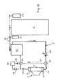
- 1 denotes an internal combustion engine, in particular a diesel engine, which is charged by means of an exhaust-gas turbocharger 2.
- This supercharged internal combustion engine 1 forms the drive source in a vehicle or a stationary power plant.
- the vehicle may be a passenger car, a commercial vehicle of any kind, a rail vehicle, watercraft or aircraft.
- the stationary power plant it may be z.
- the vehicle or the stationary power plant have components which require heating, heating or keeping warm and can be supplied with heat by a medium received in a closed circuit 3, 3 '.
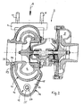
- the exhaust gas turbocharger 2 consists of an exhaust gas turbine 4 and a charge air compressor 5.
- the exhaust gas turbine 4 is connected via an exhaust manifold 6 with the exhaust gas outlets of the internal combustion engine in communication and receives exhaust gas in the direction of arrow A.
- the connection between the exhaust gas turbine 4 and the exhaust manifold 6 is made via flanges 7, 8, wherein the flange 7 at the inlet 9 of the turbine housing 10 and the flange 8 arranged at the end facing the exhaust manifold 6 and the connection of the two flanges 7, 8 made by screw 11 is.
- the charge air compressor 5 supplies the inlets of the internal combustion engine 1 via a charge air manifold.
- the turbine 4 of the exhaust gas turbocharger 2 is used and / or designed as a heating source for the medium.
- a heat exchanger 12 is arranged on the outside of the turbine housing 10, which is integrated or switchable into the medium circuit 3 and in the interior 13 of the directly or channeled medium passed through utilizing at least the thermal radiation energy of the hot turbine housing 10 is heated. Examples of the direct passage of the medium through the interior 13 of the heat exchanger 12 are shown in Figures 1, 4 and 5. By contrast, FIGS. 2 and 3 show an example of a channeled or cased passage of the medium through the interior 13 of the heat exchanger 12.
- the heat exchanger 12 can be realized in various ways outside the turbine housing 10.
- the heat exchanger 12 can be realized as an integral part of the exhaust gas turbine 4 and, for this purpose, the housing 14 of the heat exchanger 12 can be formed by the turbine housing outer wall 15 and a further housing outer wall 16 cast on or attached thereto (see FIGS. 1, 2 and 3).
- the housing 14 of the heat exchanger 12 can be formed by the turbine housing outer wall 15 and a further housing outer wall 16 cast on or attached thereto (see FIGS. 1, 2 and 3).
- an outer wall 16 of the heat exchanger housing 14 in shell form made of high temperature steel sheet by punching and stamping and then outside of the turbine housing outer wall 15 z. B. by welding or by straps are attached.
- it is also possible to realize the heat exchanger 12 with a housing 14 see FIG.
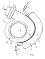
- the heat exchanger 12 may also be formed by a heat exchanger tube 18, which - as shown in FIG. 5 - bent or meandering on the turbine housing 10 of the exhaust gas turbine 4, there on the intended outdoor area - adapted to this form-fitting and intimately nestled for optimum heat transfer - is attached, z. B. by several brackets or holder 19th
- a first connection 20 and second connection 21 are provided on the housing 14 of the heat exchanger 12, wherein a supply line 22 for the medium to be heated (arrow B) and at the second, from the first (20 ) spatially spaced terminal 21 a discharge line 23 for the heated medium (arrow C) is connected.
- a supply line 22 for the medium to be heated (arrow B) and at the second, from the first (20 ) spatially spaced terminal 21 a discharge line 23 for the heated medium (arrow C) is connected.
- About the supply line 22 and the discharge line 23 of the heat exchanger 12 is incorporated into the medium circuit 3 and switched on, as further explained in more detail below.
- the medium to be heated can be introduced via the supply line 22 and the first connection directly into the interior 13 of the heat exchanger housing 14, where it is in contact with the hot outer wall 15 of the turbine housing 10 (FIG ) or heated by the latter housing outer wall portion 17 (Fig. 4) and thus can be heated and after a certain residence time from the heat exchanger housing 14 via the second port 21 and again via the discharge line 23 the medium circuit 3 to the local further Use is fed.
- a heat exchanger tube 24 extends between the first connection 20 and the second connection 21 of the heat exchanger 12, with which the medium to be heated can be channeled or piped through the interior 13 of the heat exchanger housing 14.
- the heat exchanger tube 24 may extend straight or in a meandering shape between the two terminals 20, 21.
- the heat exchanger tube 24 may be externally provided with heat-transmitting ribs 25.
- a heat exchanger tube bundle held between two collection chambers arranged at the end may also be present, which consists of a number of straight, parallel heat exchanger tubes, which are optionally further ribbed on the outside.
- the heat exchanger tube 24 or said heat exchanger tube bundle may be part of a heat exchanger cartridge 26, the -. B. from Fig. 3 can be seen - and the two ports 20, 21 contains and prefabricated in the housing 14 of the heat exchanger 12 can be installed and then extends in installation position between supply line 22 and discharge line 23.
- the heat exchanger tube 24 and the heat exchanger tube bundle receive within the closed heat exchanger housing 14 on the radiated from the outer wall 15 of the turbine 10 heat energy.
- the heating power can be increased in cases of the channelized or cased passage of the medium, that exhaust gas is fed into the interior 13 of the heat exchanger 12.
- This exhaust gas is branched from the exhaust tract 6 before or in the input 9 of the exhaust gas turbine 4 and channeled, z. B. via a turbine housing internal bore 27, as shown in FIG. 3, in the interior 13 of the heat exchanger housing 14 can be fed.
- This exhaust is then, after a certain heat-emitting residence time, from the heat exchanger 12 at a remote from the discharge point 28 point 29, z. B.
- the heat exchanger tube 18 has at the outset a first connection 32, to which the supply line 22 for the medium to be heated is attached, and at the outset a second connection 33, to which the heated medium discharge line 23 is connected.
- the heat exchanger 12 with its supply line 22 and discharge line 23 in the medium circuit 3 and 3 ', if necessary einêtbar.
- the need for this activation is z. B. at the place where the heated medium is to be effective, detected by one or more temperature sensors.
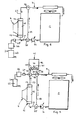
- the input and control of the heat exchanger 12 in the medium circuit 3 is z. B. by switchable changeover valves 35, 36, which receive their switching commands from an electronic control and control device (not shown) ago and which are connected to each other via a line section 37, which in the case of non-inclusion of the heat exchanger 12 then in the medium circuit. 3 , 3 'bridged as a bypass.
- the medium circuit 3 is the cooling circuit of the internal combustion engine 1 and the medium circulated therein by means of a pump 34 around the liquid coolant - cooling water or cooling water mixed with antifreeze - the internal combustion engine 1.
- the heat exchanger 12 according to the invention as needed via the switching valves 35, 36 einêtbar, z. B. whenever a rapid heating of the coolant after a cold start of the internal combustion engine 1 is required.
- This activation of the heat exchanger 12 in the cooling circuit 3 via a temperature-controlled control / with appropriate influence on the switching position of the changeover valves 35, 36th Der gravtechniker 12.
- the heat exchanger 12 is z. B. then switched out by appropriate switching of the changeover valves 35, 36 back out of the cooling circuit when the cooling water is sufficiently preheated.
- the medium circuit 3 is also the cooling circuit of the internal combustion engine 1 and the medium circulated therein by the pump 34 is water or antifreeze mixed water.
- a third switchable changeover valve 38 is provided here, to which the discharge line 23 leads and which is connected via a line section 39 to the second changeover valve 36.
- Reference numeral 40 denotes a heating circuit which consists of a heating element 41 in or on a heat consumer 42, a supply line 43 coming from the changeover valve 38 and communicating with the heating element 41 and a return line 44 coming from the heating element 41, which leads to the changeover valve 36.
- This heating circuit 40 is used for heat dissipation to the heat consumer 42, in which it is z. B.
- the heating element 41 may, for. B. within the heat consumer 42 / container just above the bottom 45 in the manner of a straight or coiled or meandering heating tube or through a depression in the bottom 45 or the wall 46 of the heat consumer 42 / container embedded heating tube or in the material of the bottom 45th or the wall 46 of the heat consumer 42 / container integrated heating tube may be formed.
- This heating circuit 40 is required, via the switching valves 35, 36, 38 in series with the heat exchanger 12 in the medium circuit 3 - here cooling circuit of the engine 1 - switched on. This activation of the heating circuit 40 and heat exchanger 12 is temperature-controlled, z. B.
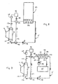
- the heat exchanger 12 instead of in the engine-side cooling circuit - as described above with reference to FIGS. 6 and 7, the heat exchanger 12 according to the invention but also in a self-sufficient, independent of the internal combustion engine 1 and the cooling circuit medium circuit 3 'be turned on or be involved.
- the medium contained in this medium circuit 3 ' can be, for example, water or antifreeze mixed water or any other suitable liquid, e.g. B. also a low-boiling liquid such as an ammonia-water mixture act.
- FIGS. 8 to 10 Examples of such self-contained medium circuits 3 'are shown in FIGS. 8 to 10.
- a heating tube 52 is provided, which is formed in the same or similar manner as the heating tube 41 of FIG. 7, arranged or wall-integrated.
- the activation of the heat exchanger 12 for the purpose of heating the medium in the medium circuit 3 'and a heat dissipation in the region of the heat consumer 47 takes place here similar to the example of FIG. 7, that is dependent on a sensed by sensor in or on the heat collector 47 temperature by appropriate influence on the switching position of the two switching valves 49, 50th
- the heat collector 47 is formed by a further heat exchanger 53, the interior of which is enclosed by a housing being integrated into the medium circuit 3 'via an inlet 55 and outlet 56, otherwise in the same construction as in FIG and is flowed through by medium therein.
- a secondary medium circuit 57 is passed, in which a circulated by a pump 58 secondary medium via a arranged in the interior 54 of the heat exchanger 53 heat exchanger tube or tube bundle 59 is conductive to the heat from the first medium circuit 3 'can be fed ,
- This thus heated secondary medium is supplied in the secondary medium circuit 57 to a heat consumer 60 incorporated therein, such as a consumer or heat storage or liquid-containing container.
- the heat taker 60 could, among other things, also be such (42, 47) as mentioned in connection with FIGS. 7 and 8.
- the heat collector 47 is a steam turbine 61 which can supply the medium transferred to its vaporous state in the heat exchanger 12 and output it there with relaxation and cooling is effective.
- the steam turbine 61 is drivingly connected to the crankshaft 1 'of the internal combustion engine 1 and / or ancillaries 62, 63 of the same, such as alternator, generator, pumps, air compressor, etc. connected via one or more switchable coupling (s) and uncoupled, whereby the steam energy can be converted into mechanical energy.
- the respective drive trains or strands are designated 64.
- a preferably electronic, computer-aided operating control and control device is provided in all applications, the program by program and predetermined stored values based on their supplied actual values, such as heat consumer temperature values and flow and pressure values in the medium circuits 3, 3 '57, the operation and the rotational speeds of the pumps 34, 48, 58 and the switching / switching of the switching valves 35, 36, 38, 49, 50 controls for activation and deactivation of the heat exchanger 12 as a heat source.
- the heat exchanger 12 can act on the exhaust gas turbine 4 of the exhaust gas turbocharger to some extent as a cooling element, because he at least partially shields the turbine housing outside and thus reduces its outward heat radiation, in particular in connection with the medium flowing through.
- external thermal insulation or shields either completely omitted or need only be reduced or simplified realized.
Landscapes
- Engineering & Computer Science (AREA)
- Chemical & Material Sciences (AREA)
- Mechanical Engineering (AREA)
- General Engineering & Computer Science (AREA)
- Combustion & Propulsion (AREA)
- Chemical Kinetics & Catalysis (AREA)
- General Chemical & Material Sciences (AREA)
- Air-Conditioning For Vehicles (AREA)
- Supercharger (AREA)
- Engine Equipment That Uses Special Cycles (AREA)
- Heat-Exchange Devices With Radiators And Conduit Assemblies (AREA)
Priority Applications (4)
| Application Number | Priority Date | Filing Date | Title |
|---|---|---|---|
| PL07003700T PL1835164T3 (pl) | 2006-03-15 | 2007-02-23 | Pojazd albo stacjonarna instalacja energetyczna z doładowanym silnikiem spalinowym jako wał napędowy |
| EP19187027.8A EP3591189A1 (fr) | 2006-03-15 | 2007-02-23 | Véhicule ou syst?me de puissance fixe comprenant un moteur à combustion interne chargé en tant que source d'entraînement |
| EP19187028.6A EP3591200A1 (fr) | 2006-03-15 | 2007-02-23 | Véhicule ou syst?me de puissance fixe comprenant un moteur à combustion interne chargé en tant que source d'entraînement |
| EP19187030.2A EP3591201A1 (fr) | 2006-03-15 | 2007-02-23 | Véhicule ou syst?me de puissance fixe comprenant un moteur à combustion interne chargé en tant que source d'entraînement |
Applications Claiming Priority (1)
| Application Number | Priority Date | Filing Date | Title |
|---|---|---|---|
| DE102006011797A DE102006011797A1 (de) | 2006-03-15 | 2006-03-15 | Fahrzeug oder stationäre Kraftanlage mit einer aufgeladenen Brennkraftmaschine als Antriebsquelle |
Related Child Applications (6)
| Application Number | Title | Priority Date | Filing Date |
|---|---|---|---|
| EP19187030.2A Division-Into EP3591201A1 (fr) | 2006-03-15 | 2007-02-23 | Véhicule ou syst?me de puissance fixe comprenant un moteur à combustion interne chargé en tant que source d'entraînement |
| EP19187030.2A Division EP3591201A1 (fr) | 2006-03-15 | 2007-02-23 | Véhicule ou syst?me de puissance fixe comprenant un moteur à combustion interne chargé en tant que source d'entraînement |
| EP19187027.8A Division EP3591189A1 (fr) | 2006-03-15 | 2007-02-23 | Véhicule ou syst?me de puissance fixe comprenant un moteur à combustion interne chargé en tant que source d'entraînement |
| EP19187027.8A Division-Into EP3591189A1 (fr) | 2006-03-15 | 2007-02-23 | Véhicule ou syst?me de puissance fixe comprenant un moteur à combustion interne chargé en tant que source d'entraînement |
| EP19187028.6A Division-Into EP3591200A1 (fr) | 2006-03-15 | 2007-02-23 | Véhicule ou syst?me de puissance fixe comprenant un moteur à combustion interne chargé en tant que source d'entraînement |
| EP19187028.6A Division EP3591200A1 (fr) | 2006-03-15 | 2007-02-23 | Véhicule ou syst?me de puissance fixe comprenant un moteur à combustion interne chargé en tant que source d'entraînement |
Publications (3)
| Publication Number | Publication Date |
|---|---|
| EP1835164A2 true EP1835164A2 (fr) | 2007-09-19 |
| EP1835164A3 EP1835164A3 (fr) | 2014-08-20 |
| EP1835164B1 EP1835164B1 (fr) | 2019-12-25 |
Family
ID=38121285
Family Applications (4)
| Application Number | Title | Priority Date | Filing Date |
|---|---|---|---|
| EP19187028.6A Withdrawn EP3591200A1 (fr) | 2006-03-15 | 2007-02-23 | Véhicule ou syst?me de puissance fixe comprenant un moteur à combustion interne chargé en tant que source d'entraînement |
| EP19187030.2A Withdrawn EP3591201A1 (fr) | 2006-03-15 | 2007-02-23 | Véhicule ou syst?me de puissance fixe comprenant un moteur à combustion interne chargé en tant que source d'entraînement |
| EP19187027.8A Withdrawn EP3591189A1 (fr) | 2006-03-15 | 2007-02-23 | Véhicule ou syst?me de puissance fixe comprenant un moteur à combustion interne chargé en tant que source d'entraînement |
| EP07003700.7A Active EP1835164B1 (fr) | 2006-03-15 | 2007-02-23 | Véhicule ou centrale stationnaire doté(e) d'un moteur à combustion interne chargé comme arbre d'entraînement |
Family Applications Before (3)
| Application Number | Title | Priority Date | Filing Date |
|---|---|---|---|
| EP19187028.6A Withdrawn EP3591200A1 (fr) | 2006-03-15 | 2007-02-23 | Véhicule ou syst?me de puissance fixe comprenant un moteur à combustion interne chargé en tant que source d'entraînement |
| EP19187030.2A Withdrawn EP3591201A1 (fr) | 2006-03-15 | 2007-02-23 | Véhicule ou syst?me de puissance fixe comprenant un moteur à combustion interne chargé en tant que source d'entraînement |
| EP19187027.8A Withdrawn EP3591189A1 (fr) | 2006-03-15 | 2007-02-23 | Véhicule ou syst?me de puissance fixe comprenant un moteur à combustion interne chargé en tant que source d'entraînement |
Country Status (6)
| Country | Link |
|---|---|
| US (2) | US20070214789A1 (fr) |
| EP (4) | EP3591200A1 (fr) |
| CN (1) | CN101037977B (fr) |
| DE (1) | DE102006011797A1 (fr) |
| PL (1) | PL1835164T3 (fr) |
| RU (1) | RU2347096C2 (fr) |
Cited By (8)
| Publication number | Priority date | Publication date | Assignee | Title |
|---|---|---|---|---|
| EP2320047A1 (fr) * | 2008-09-01 | 2011-05-11 | Yanmar Co., Ltd. | Structure de refroidissement d'un compresseur volumétrique |
| WO2012107487A1 (fr) * | 2011-02-10 | 2012-08-16 | Continental Automotive Gmbh | Turbocompresseur à gaz d'échappement, à refroidissement du carter de turbine et à réduction des pertes de pression |
| DE202015101744U1 (de) | 2015-04-07 | 2015-04-23 | Ford Global Technologies, Llc | Vorrichtung zur Energierückgewinnung an einem Verbrennungsmotor mit Abgasturbolader als Wärmequelle für einen Dampfkraftmaschinenkreislauf |
| DE102016205267A1 (de) | 2015-04-07 | 2016-10-13 | Ford Global Technologies, Llc | Vorrichtung zur Energierückgewinnung an einem Verbrennungsmotor mit Abgasturbolader als Wärmequelle für einen Dampfkraftmaschinenkreislauf und Verfahren zum Betrieb der Vorrichtung |
| DE102015206151A1 (de) | 2015-04-07 | 2016-10-13 | Ford Global Technologies, Llc | Vorrichtung zur Energierückgewinnung an einem Verbrennungsmotor mit Abgasturbolader als Wärmequelle für einen Dampfkraftmaschinenkreislauf und Verfahren zum Betrieb der Vorrichtung |
| DE102016220672A1 (de) | 2015-11-16 | 2017-05-18 | Ford Global Technologies, Llc | Kraftfahrzeug mit Wärmenutzvorrichtung |
| DE102016208784A1 (de) | 2016-05-20 | 2017-11-23 | Ford Global Technologies, Llc | Kraftfahrzeug mit Wärmewandler |
| EP2543846B1 (fr) * | 2011-07-04 | 2018-11-21 | IVECO S.p.A. | Compresseur volumétrique pour véhicule industriel avec caractéristiques de connexion améliorées sur le circuit de refroidissement et véhicule industriel comportant un tel compresseur volumétrique |
Families Citing this family (48)
| Publication number | Priority date | Publication date | Assignee | Title |
|---|---|---|---|---|
| DE102007052118A1 (de) * | 2007-10-30 | 2009-05-07 | Voith Patent Gmbh | Verfahren zur Steuerung der Leistungsübertragung in einem Antriebsstrang mit einem Turbocompoundsystem und Antriebsstrang |
| DE202008002696U1 (de) * | 2008-02-26 | 2009-07-02 | Voss Automotive Gmbh | System zum Temperieren eines SCR-Additivs in einem Kraftfahrzeug |
| DE102008011258A1 (de) * | 2008-02-27 | 2009-09-10 | Continental Automotive Gmbh | Gekühltes Gehäuse bestehend aus einem Turbinengehäuse und einem Lagergehäuse eines Turboladers |
| DE102008011257A1 (de) * | 2008-02-27 | 2009-09-10 | Continental Automotive Gmbh | Gekühltes Turbinengehäuse |
| EP2281111A4 (fr) * | 2008-04-25 | 2014-01-15 | New Power Concepts Llc | Systeme de recuperation d'energie thermique |
| GB0903830D0 (en) * | 2009-03-06 | 2009-04-22 | Cummins Turbo Tech Ltd | Gas expander system |
| DE102009028632A1 (de) * | 2009-08-19 | 2011-03-03 | Ford Global Technologies, LLC, Dearborn | Flüssigkeitsgekühlte Brennkraftmaschine mit flüssigkeitsgekühlter Turbine |
| DE102009044258A1 (de) * | 2009-10-15 | 2011-05-05 | Krones Ag | Anlage und Verfahren zur Herstellung, Abfüllung, Verpackung und/oder Transport von Getränken |
| DE102009054403A1 (de) * | 2009-11-24 | 2011-05-26 | Bosch Mahle Turbo Systems Gmbh & Co. Kg | Abgasturbolader |
| AT509395B1 (de) * | 2010-01-15 | 2012-08-15 | Man Truck & Bus Oesterreich Ag | System zur abwärmenutzung einer brennkraftmaschine mit einfrierschutzeinrichtung |
| DE102010005824A1 (de) * | 2010-01-27 | 2011-07-28 | GM Global Technology Operations LLC, ( n. d. Ges. d. Staates Delaware ), Mich. | Flüssigkeitskühlsystem eines durch einen Turbolader aufgeladenen Verbrennungsmotors und Verfahren zur Kühlung eines Turbinengehäuses eines Turboladers |
| DE102010011293B4 (de) | 2010-03-13 | 2022-07-07 | Dr. Ing. H.C. F. Porsche Aktiengesellschaft | Brennkraftmaschine |
| DE102010015106B4 (de) * | 2010-04-16 | 2013-05-16 | Audi Ag | Kühlmittelkreislauf für eine Brennkraftmaschine eines Kraftfahrzeugs |
| EP2392794B1 (fr) * | 2010-06-07 | 2019-02-27 | Ford Global Technologies, LLC | Turbosoufflante refroidie séparément pour le maintien d'une stratégie sans écoulement d'une enveloppe de réfrigérant à bloc cylindre |
| DE102010017558A1 (de) * | 2010-06-24 | 2011-12-29 | Ford Global Technologies, Llc. | Brennkraftmaschine mit Zylinderkopf und Turbine und Verfahren zum Betreiben einer derartigen Brennkraftmaschine |
| JP5494294B2 (ja) * | 2010-06-30 | 2014-05-14 | マツダ株式会社 | 車両用エンジンのターボ過給機の冷却装置 |
| KR101925423B1 (ko) | 2010-10-11 | 2019-02-27 | 보르그워너 인코퍼레이티드 | 내연기관의 배기가스 터보차저 |
| DE102011085961A1 (de) * | 2011-11-08 | 2013-05-08 | Behr Gmbh & Co. Kg | Kühlkreislauf |
| DE102011056838B4 (de) * | 2011-12-21 | 2022-07-07 | Dr. Ing. H.C. F. Porsche Ag | Kühlvorrichtung für ein Nebenaggregat |
| KR102036846B1 (ko) * | 2012-05-29 | 2019-10-25 | 보르그워너 인코퍼레이티드 | 배기가스 터보차저 |
| CN102730708A (zh) * | 2012-07-04 | 2012-10-17 | 青岛东岳罗地亚化工有限公司 | 链板机余热回收利用装置及泡花碱制造系统 |
| CN103233804A (zh) * | 2012-08-24 | 2013-08-07 | 褚凤红 | 摩托车排气管的废热利用容器 |
| RU2507462C1 (ru) * | 2012-11-06 | 2014-02-20 | Юлия Алексеевна Щепочкина | Приспособление для размораживания чугунных радиаторов |
| KR20150034848A (ko) * | 2013-09-25 | 2015-04-06 | 현대자동차주식회사 | 냉각구조를 갖는 터보차저 |
| JP5971232B2 (ja) * | 2013-12-24 | 2016-08-17 | トヨタ自動車株式会社 | 機関システムの制御装置 |
| JP6040928B2 (ja) * | 2013-12-25 | 2016-12-07 | トヨタ自動車株式会社 | ターボチャージャ |
| JP6070587B2 (ja) * | 2014-01-22 | 2017-02-01 | トヨタ自動車株式会社 | 内燃機関 |
| US9556824B2 (en) * | 2014-03-25 | 2017-01-31 | Hanon Systems | Integration of forced EGR/EGR-pump into EGR-cooler |
| JP5975057B2 (ja) * | 2014-04-15 | 2016-08-23 | トヨタ自動車株式会社 | タービンハウジング |
| JP6137032B2 (ja) * | 2014-04-15 | 2017-05-31 | トヨタ自動車株式会社 | タービンハウジング |
| US9441534B2 (en) * | 2014-10-09 | 2016-09-13 | GM Global Technology Operations LLC | Cooled two-stage turbocharging system |
| US20160177814A1 (en) * | 2014-12-23 | 2016-06-23 | Caterpillar Inc. | Removal of Heat in Exhaust Shielding with Jacket Fluid Cooled Components |
| JP6220803B2 (ja) * | 2015-03-18 | 2017-10-25 | 株式会社豊田自動織機 | ターボチャージャ |
| DE102015205544B4 (de) | 2015-03-26 | 2023-03-09 | Ford Global Technologies, Llc | Motorbaugruppe für ein Kraftfahrzeug |
| US11214381B2 (en) | 2015-08-07 | 2022-01-04 | Pratt & Whitney Canada Corp. | Aircraft heating assembly with liquid cooled internal combustion engine and heating element using waste heat |
| WO2017083107A1 (fr) * | 2015-11-09 | 2017-05-18 | Borgwarner Inc. | Système de transfert de chaleur pour turbocompresseur |
| DE102015016030A1 (de) * | 2015-12-11 | 2017-06-14 | Man Truck & Bus Ag | Abgasturbolader für ein Kraftfahrzeug |
| DE102016213386A1 (de) * | 2016-07-21 | 2018-01-25 | Ford Global Technologies, Llc | Brennkraftmaschine mit Abgasturboaufladung und Verfahren zum Betreiben einer derartigen Brennkraftmaschine |
| CN106194402B (zh) * | 2016-09-19 | 2018-08-31 | 吉林大学 | 一种蓄热式复合涡轮增压装置 |
| JP7109721B2 (ja) * | 2017-02-10 | 2022-08-01 | イーアイエム リサーチ ピーティーワイ リミテッド | ガスデストラクションのための方法および装置 |
| DE102017105756A1 (de) * | 2017-03-17 | 2018-09-20 | Man Diesel & Turbo Se | Turbolader |
| AU2018203112B2 (en) * | 2017-05-05 | 2024-03-07 | VENTICO Australia Pty Limited | Turbocharger assembly |
| EP3486450A1 (fr) * | 2017-11-15 | 2019-05-22 | Perkins Engines Company Limited | Soupape de commande d'écoulement d'échappement comprenant une soupape de décharge intégrée |
| CN108060950A (zh) * | 2017-12-07 | 2018-05-22 | 许润柱 | 一种热电联产及产品 |
| US10914219B2 (en) * | 2019-02-13 | 2021-02-09 | Indmar Products Company, Inc. | Heat shield for a marine engine exhaust system |
| CN112576361B (zh) * | 2019-09-30 | 2022-10-04 | 广州汽车集团股份有限公司 | 基于温控模块的快速暖机方法及快速暖机装置 |
| CN114256487B (zh) * | 2021-12-27 | 2024-06-25 | 上海重塑能源科技有限公司 | 防冷冻燃料电池冷启动系统、燃料电池系统及融冰方法 |
| CN114215638A (zh) * | 2021-12-30 | 2022-03-22 | 康跃科技(山东)有限公司 | 一种气隙介质电辅助增压器冷却结构 |
Citations (12)
| Publication number | Priority date | Publication date | Assignee | Title |
|---|---|---|---|---|
| DE2625745B1 (de) * | 1976-06-04 | 1977-12-15 | Sulzer Ag | Dieselbrennkraftmaschinenanlage fuer schiffsantrieb |
| JPS56173724U (fr) * | 1980-05-26 | 1981-12-22 | ||
| JPS59188058A (ja) * | 1983-04-08 | 1984-10-25 | Yamaha Motor Co Ltd | 内燃機関の廃熱利用装置 |
| JPS6252238U (fr) * | 1985-09-19 | 1987-04-01 | ||
| JPH0421724U (fr) * | 1990-06-13 | 1992-02-24 | ||
| EP0634565A1 (fr) * | 1993-07-12 | 1995-01-18 | MAN Nutzfahrzeuge Aktiengesellschaft | Procédé d'amélioration du comportement de démarrage à froid des moteurs à combustion interne |
| WO2000031400A2 (fr) * | 1998-11-24 | 2000-06-02 | Claudio Filippone | Moteur miniature d'energie residuelle |
| JP2001207857A (ja) * | 2000-01-20 | 2001-08-03 | Nkk Plant Engineering Corp | 沸騰冷却式過給機、その過給機を備えたコジェネレーションシステム |
| DE10025500A1 (de) * | 2000-05-23 | 2001-11-29 | Bosch Gmbh Robert | Brennkraftmaschine mit Kühlkreislauf und einem an diesen angeschlossenen Heizungswärmetauscher |
| DE10344868A1 (de) * | 2003-09-26 | 2005-04-21 | Volkswagen Ag | Abgasturbolader |
| GB2414690A (en) * | 2004-06-04 | 2005-12-07 | Ford Global Tech Llc | An emission control apparatus for an engine |
| WO2006025110A1 (fr) * | 2004-09-02 | 2006-03-09 | Nissan Diesel Motor Co., Ltd. | Épurateur de gaz d'échappement |
Family Cites Families (40)
| Publication number | Priority date | Publication date | Assignee | Title |
|---|---|---|---|---|
| US2692759A (en) * | 1951-09-27 | 1954-10-26 | Otto Wanek | Steam operated heater system and/or apparatus with control therefor |
| US2866617A (en) * | 1953-05-11 | 1958-12-30 | Elliott Co | Shielded gas turbine |
| US3222883A (en) * | 1963-09-09 | 1965-12-14 | Boeing Co | Temperature and humidity control systems for enclosures |
| US3605406A (en) * | 1969-06-27 | 1971-09-20 | Raymond L Woolley | Combined gas and steam power plant |
| US3986938A (en) * | 1972-02-07 | 1976-10-19 | Smith Jr Calvin S | Direct contact of low-boiling, water-immiscible medium with hot and cold bodies of water to transfer heat for purposes of energy production and/or desalination |
| DE2252705A1 (de) * | 1972-10-27 | 1974-05-02 | Daimler Benz Ag | Anbau eines abgasturboladers an eine brennkraftmaschine |
| US4068612A (en) * | 1976-01-26 | 1978-01-17 | M & W Gear Company | Turbocharger housing construction for marine turbocharger and device for turbocharging a marine engine |
| ES461142A1 (es) * | 1976-09-04 | 1978-06-01 | Mtu Friedrichshafen Gmbh | Mejoras en turbo-cargadores de gas de escape para maquinas motrices de combustion. |
| CH632559A5 (en) * | 1978-08-15 | 1982-10-15 | Sulzer Ag | Method for the operation of a ship's propulsion system and device for performing the method |
| JPS5981739U (ja) * | 1982-11-24 | 1984-06-02 | トヨタ自動車株式会社 | インタ−ク−ラ付水冷タ−ボチヤ−ジヤ |
| US4520767A (en) * | 1983-09-16 | 1985-06-04 | Cummins Engine Company | Low flow cooling system and apparatus |
| JPS6090923A (ja) * | 1983-10-25 | 1985-05-22 | Mitsubishi Motors Corp | 排気タ−ボチヤ−ジヤ付エンジンの冷却装置 |
| JPS60212617A (ja) * | 1984-04-06 | 1985-10-24 | Yanmar Diesel Engine Co Ltd | 水冷式タ−ボチヤ−ジヤ−冷却装置 |
| DE3439738C2 (de) * | 1984-10-31 | 1986-12-11 | Mtu Motoren- Und Turbinen-Union Friedrichshafen Gmbh, 7990 Friedrichshafen | Aufgeladene Brennkraftmaschine |
| US5087176A (en) * | 1984-12-20 | 1992-02-11 | Allied-Signal Inc. | Method and apparatus to provide thermal isolation of process gas bearings |
| JPS62294724A (ja) * | 1986-06-16 | 1987-12-22 | Toshiba Corp | タ−ボチヤ−ジヤのタ−ビンケ−シング冷却装置 |
| US5020319A (en) * | 1987-06-09 | 1991-06-04 | Ngk Spark Plug Co., Ltd. | Hollow heat-resisting body assembly for internal combustion engine |
| JP2533346B2 (ja) * | 1987-12-29 | 1996-09-11 | ヤンマーディーゼル株式会社 | タ―ボチャ―ジャ―の冷却構造 |
| KR900008584B1 (ko) * | 1988-08-26 | 1990-11-26 | 김용구 | 자동차 폐열을 이용한 냉·난방 겸용 동력발생장치 |
| DE3836463C2 (de) * | 1988-10-26 | 1998-09-10 | Ruhrgas Ag | Verfahren und Vorrichtung zur Nutzung der Abwärme eines Prozesses |
| US5161960A (en) * | 1991-11-12 | 1992-11-10 | Allied-Signal Inc. | Turbocharger with liquid cooled housing |
| DE4235830A1 (de) * | 1992-10-23 | 1994-04-28 | Man Nutzfahrzeuge Ag | Wärmespeichersystem für den Kaltstart von Verbrennungsmaschinen |
| FI102405B1 (fi) * | 1993-07-08 | 1998-11-30 | Waertsilae Nsd Oy Ab | Menetelmä lämpövoimakoneen kokonaishyötyenergiatuotannon parantamiseksi ja voimalaitos, jossa on nestejäähdytteinen lämpövoimakone |
| DE4342572C1 (de) * | 1993-12-14 | 1994-11-24 | Mtu Friedrichshafen Gmbh | Abgasanlage für eine aufgeladene Brennkraftmaschine |
| SE0001313D0 (sv) * | 2000-04-10 | 2000-04-10 | Jerzy Chomiak | Turbocharger utilizing waste heat of an internal combustion engine |
| US6374612B1 (en) * | 2000-09-21 | 2002-04-23 | Caterpillar Inc. | Interstage cooling of a multi-compressor turbocharger |
| DE10061846B4 (de) * | 2000-12-12 | 2004-09-09 | Daimlerchrysler Ag | Abgasturbolader für eine Brennkraftmaschine |
| JP3802799B2 (ja) * | 2001-11-21 | 2006-07-26 | 本田技研工業株式会社 | 熱交換装置 |
| AU2002951688A0 (en) * | 2002-09-25 | 2002-10-17 | Dbt Diesel Pty Limited | Turbocharged compression ignition engine |
| US7305829B2 (en) * | 2003-05-09 | 2007-12-11 | Recurrent Engineering, Llc | Method and apparatus for acquiring heat from multiple heat sources |
| JP2004353589A (ja) * | 2003-05-30 | 2004-12-16 | Nissan Diesel Motor Co Ltd | 水冷ターボチャージャの冷却機構 |
| CN2729332Y (zh) * | 2003-12-05 | 2005-09-28 | 弥勒县民政福利公司红河机械配件厂 | 汽车柴油发动机用水冷增压器 |
| US20050279093A1 (en) * | 2004-06-17 | 2005-12-22 | Lin-Shu Wang | Supercharged intercooled engine using turbo-cool principle and method for operating the same |
| JP2006090156A (ja) * | 2004-09-21 | 2006-04-06 | Shin Caterpillar Mitsubishi Ltd | 廃熱エネルギ再生方法および廃熱エネルギ再生装置 |
| JP2007211681A (ja) * | 2006-02-09 | 2007-08-23 | Sanden Corp | 動力回収システム |
| JP2008019711A (ja) * | 2006-07-10 | 2008-01-31 | Toyota Motor Corp | 内燃機関の過給機システム |
| JP4908383B2 (ja) * | 2006-11-24 | 2012-04-04 | ベール ゲーエムベーハー ウント コー カーゲー | 少なくとも1つの膨張装置を駆動するための有機ランキンサイクル循環を備えたシステム及び膨張装置を駆動するための熱交換器並びに少なくとも1つの膨張装置を運転するための方法 |
| JP2008215184A (ja) * | 2007-03-05 | 2008-09-18 | Hitachi Ltd | ガスタービン,ガスタービン制御装置、及びその制御方法 |
| JP2008267257A (ja) * | 2007-04-19 | 2008-11-06 | Toyota Motor Corp | 過給機 |
| CN201071740Y (zh) * | 2007-09-05 | 2008-06-11 | 宁波天力增压器有限公司 | 一种小型混流涡轮增压器的水冷涡轮箱结构 |
-
2006
- 2006-03-15 DE DE102006011797A patent/DE102006011797A1/de not_active Ceased
-
2007
- 2007-02-23 EP EP19187028.6A patent/EP3591200A1/fr not_active Withdrawn
- 2007-02-23 EP EP19187030.2A patent/EP3591201A1/fr not_active Withdrawn
- 2007-02-23 PL PL07003700T patent/PL1835164T3/pl unknown
- 2007-02-23 EP EP19187027.8A patent/EP3591189A1/fr not_active Withdrawn
- 2007-02-23 EP EP07003700.7A patent/EP1835164B1/fr active Active
- 2007-03-14 RU RU2007109422/06A patent/RU2347096C2/ru active
- 2007-03-14 US US11/686,149 patent/US20070214789A1/en not_active Abandoned
- 2007-03-15 CN CN2007100863913A patent/CN101037977B/zh active Active
-
2009
- 2009-10-12 US US12/577,665 patent/US8365526B2/en active Active
Patent Citations (14)
| Publication number | Priority date | Publication date | Assignee | Title |
|---|---|---|---|---|
| DE2625745B1 (de) * | 1976-06-04 | 1977-12-15 | Sulzer Ag | Dieselbrennkraftmaschinenanlage fuer schiffsantrieb |
| JPS56173724U (fr) * | 1980-05-26 | 1981-12-22 | ||
| JPS59188058A (ja) * | 1983-04-08 | 1984-10-25 | Yamaha Motor Co Ltd | 内燃機関の廃熱利用装置 |
| JPS6252238U (fr) * | 1985-09-19 | 1987-04-01 | ||
| JPH0421724U (fr) * | 1990-06-13 | 1992-02-24 | ||
| EP0634565A1 (fr) * | 1993-07-12 | 1995-01-18 | MAN Nutzfahrzeuge Aktiengesellschaft | Procédé d'amélioration du comportement de démarrage à froid des moteurs à combustion interne |
| WO2000031400A2 (fr) * | 1998-11-24 | 2000-06-02 | Claudio Filippone | Moteur miniature d'energie residuelle |
| JP2001207857A (ja) * | 2000-01-20 | 2001-08-03 | Nkk Plant Engineering Corp | 沸騰冷却式過給機、その過給機を備えたコジェネレーションシステム |
| DE10025500A1 (de) * | 2000-05-23 | 2001-11-29 | Bosch Gmbh Robert | Brennkraftmaschine mit Kühlkreislauf und einem an diesen angeschlossenen Heizungswärmetauscher |
| DE10344868A1 (de) * | 2003-09-26 | 2005-04-21 | Volkswagen Ag | Abgasturbolader |
| GB2414690A (en) * | 2004-06-04 | 2005-12-07 | Ford Global Tech Llc | An emission control apparatus for an engine |
| DE102005025434A1 (de) * | 2004-06-04 | 2005-12-29 | Ford Global Technologies, LLC (n.d.Ges.d. Staates Delaware), Dearborn | Schadstoffbegrenzungseinrichtung für einen Motor |
| WO2006025110A1 (fr) * | 2004-09-02 | 2006-03-09 | Nissan Diesel Motor Co., Ltd. | Épurateur de gaz d'échappement |
| EP1785606A1 (fr) * | 2004-09-02 | 2007-05-16 | Nissan Diesel Motor Co., Ltd. | Épurateur de gaz d'échappement |
Cited By (13)
| Publication number | Priority date | Publication date | Assignee | Title |
|---|---|---|---|---|
| EP2320047A1 (fr) * | 2008-09-01 | 2011-05-11 | Yanmar Co., Ltd. | Structure de refroidissement d'un compresseur volumétrique |
| EP2320047A4 (fr) * | 2008-09-01 | 2014-05-14 | Yanmar Co Ltd | Structure de refroidissement d'un compresseur volumétrique |
| US8826661B2 (en) | 2008-09-01 | 2014-09-09 | Yanmar Co., Ltd. | Cooling structure of supercharger |
| WO2012107487A1 (fr) * | 2011-02-10 | 2012-08-16 | Continental Automotive Gmbh | Turbocompresseur à gaz d'échappement, à refroidissement du carter de turbine et à réduction des pertes de pression |
| US9476319B2 (en) | 2011-02-10 | 2016-10-25 | Continental Automotive Gmbh | Turbocharger with cooled turbine housing and reduced pressure loss |
| EP2543846B1 (fr) * | 2011-07-04 | 2018-11-21 | IVECO S.p.A. | Compresseur volumétrique pour véhicule industriel avec caractéristiques de connexion améliorées sur le circuit de refroidissement et véhicule industriel comportant un tel compresseur volumétrique |
| DE102015206151A1 (de) | 2015-04-07 | 2016-10-13 | Ford Global Technologies, Llc | Vorrichtung zur Energierückgewinnung an einem Verbrennungsmotor mit Abgasturbolader als Wärmequelle für einen Dampfkraftmaschinenkreislauf und Verfahren zum Betrieb der Vorrichtung |
| DE102016205267A1 (de) | 2015-04-07 | 2016-10-13 | Ford Global Technologies, Llc | Vorrichtung zur Energierückgewinnung an einem Verbrennungsmotor mit Abgasturbolader als Wärmequelle für einen Dampfkraftmaschinenkreislauf und Verfahren zum Betrieb der Vorrichtung |
| DE202015101744U1 (de) | 2015-04-07 | 2015-04-23 | Ford Global Technologies, Llc | Vorrichtung zur Energierückgewinnung an einem Verbrennungsmotor mit Abgasturbolader als Wärmequelle für einen Dampfkraftmaschinenkreislauf |
| DE102016205267B4 (de) * | 2015-04-07 | 2021-02-25 | Ford Global Technologies, Llc | Vorrichtung zur Energierückgewinnung an einem Verbrennungsmotor mit Abgasturbolader als Wärmequelle für einen Dampfkraftmaschinenkreislauf und Verfahren zum Betrieb der Vorrichtung |
| DE102016220672A1 (de) | 2015-11-16 | 2017-05-18 | Ford Global Technologies, Llc | Kraftfahrzeug mit Wärmenutzvorrichtung |
| DE102016220672B4 (de) * | 2015-11-16 | 2021-03-11 | Ford Global Technologies, Llc | Kraftfahrzeug mit Wärmenutzvorrichtung |
| DE102016208784A1 (de) | 2016-05-20 | 2017-11-23 | Ford Global Technologies, Llc | Kraftfahrzeug mit Wärmewandler |
Also Published As
| Publication number | Publication date |
|---|---|
| US20100146969A1 (en) | 2010-06-17 |
| EP3591189A1 (fr) | 2020-01-08 |
| RU2347096C2 (ru) | 2009-02-20 |
| US20070214789A1 (en) | 2007-09-20 |
| EP1835164B1 (fr) | 2019-12-25 |
| US8365526B2 (en) | 2013-02-05 |
| PL1835164T3 (pl) | 2020-06-01 |
| CN101037977A (zh) | 2007-09-19 |
| CN101037977B (zh) | 2010-04-21 |
| DE102006011797A1 (de) | 2007-09-20 |
| EP3591201A1 (fr) | 2020-01-08 |
| EP1835164A3 (fr) | 2014-08-20 |
| EP3591200A1 (fr) | 2020-01-08 |
| RU2007109422A (ru) | 2008-09-20 |
Similar Documents
| Publication | Publication Date | Title |
|---|---|---|
| EP1835164B1 (fr) | Véhicule ou centrale stationnaire doté(e) d'un moteur à combustion interne chargé comme arbre d'entraînement | |
| EP2464839B1 (fr) | Dispositif d'utilisation de chaleur dissipee | |
| DE10324482B4 (de) | Vorrichtung zur Dosierung eines Reduktionsmittels zum Abgas eines Verbrennungsmotors | |
| EP1767417B2 (fr) | Usage d'un système de réservoir avec un réservoir principal et un dispositif de fusion avec un réservoir de fusion | |
| EP2863022B1 (fr) | Unité d'entraînement pour un véhicule automobile | |
| DE102010054912B4 (de) | Dosieranordnung und Verfahren zum Betreiben einer Dosieranordnung | |
| EP2846017B1 (fr) | Dispositif d'échange thermique et unité d'entraînement pour un véhicule automobile | |
| WO2010106179A1 (fr) | Procédé et dispositif de lubrification à l'huile de composants rotatifs ou oscillants | |
| WO2014044481A1 (fr) | Circuit de fluide de refroidissement pour véhicules | |
| EP2655106B1 (fr) | Véhicule à moteur muni d'une installation de climatisation | |
| DE102005046029A1 (de) | Kaltstartheizung zur Abschmelzung der für einen Flüssigkeitsverbraucher bestimmten Flüssigkeit in Kraftfahrzeugtanks | |
| DE102009059982A1 (de) | Verfahren zum Temperieren einer Stromquelle eines Fahrzeugs | |
| EP2983928A1 (fr) | Système de chauffage et procédé permettant de chauffer l'habitacle d'un véhicule comprenant un moteur à combustion interne | |
| DE102007042836A1 (de) | Vorrichtung zur Abgasnachbehandlung eines Abgasstroms eines Kraftfahrzeuges | |
| DE2916216A1 (de) | Einrichtung zur erwaermung von teilen einer brennkraftmaschine | |
| DE102014003580A1 (de) | Kühlanordnung und Verfahren zum Kühlen einer Dosiereinrichtung | |
| DE102017200328A1 (de) | Harnstoffbehälter als Wärmespeicher | |
| EP2096699A2 (fr) | Installation de température pour cellules combustibles et procédé de réglage des températures de cellules combustibles | |
| DE19908088A1 (de) | Brennkraftmaschine, insbesondere Diesel-Brennkraftmaschine, für ein Fahrzeug mit einer Fahrgastraum-Heizvorrichtung | |
| DE19631981B4 (de) | Vorrichtung zum Kühlen eines Kraftstoffes eines geschlossenen Kraftstoffversorgungskreislaufes eines Dieselaggregats | |
| DE102008006630A1 (de) | Vorrichtung zur Abgasnachbehandlung eines Abgasstroms eines Kraftfahrzeuges | |
| DE102014014423B4 (de) | Anordnungsstruktur eines Abgaswärmetauschers | |
| EP3191701A1 (fr) | Procédé pour réchauffer un carburant ainsi que système de chauffage de réservoir et système de réchauffage de carburant | |
| DE102014209031B4 (de) | Kraftfahrzeug mit einer einen Wärmespeicher aufweisenden Temperiervorrichtung | |
| DE102010061753A1 (de) | Latentwärmespeicher |
Legal Events
| Date | Code | Title | Description |
|---|---|---|---|
| PUAI | Public reference made under article 153(3) epc to a published international application that has entered the european phase |
Free format text: ORIGINAL CODE: 0009012 |
|
| AK | Designated contracting states |
Kind code of ref document: A2 Designated state(s): AT BE BG CH CY CZ DE DK EE ES FI FR GB GR HU IE IS IT LI LT LU LV MC NL PL PT RO SE SI SK TR |
|
| AX | Request for extension of the european patent |
Extension state: AL BA HR MK YU |
|
| RAP1 | Party data changed (applicant data changed or rights of an application transferred) |
Owner name: MAN TRUCK & BUS AG |
|
| RIC1 | Information provided on ipc code assigned before grant |
Ipc: F02C 6/12 20060101ALI20120716BHEP Ipc: F01N 5/02 20060101ALI20120716BHEP Ipc: F02G 5/02 20060101AFI20120716BHEP |
|
| PUAL | Search report despatched |
Free format text: ORIGINAL CODE: 0009013 |
|
| AK | Designated contracting states |
Kind code of ref document: A3 Designated state(s): AT BE BG CH CY CZ DE DK EE ES FI FR GB GR HU IE IS IT LI LT LU LV MC NL PL PT RO SE SI SK TR |
|
| AX | Request for extension of the european patent |
Extension state: AL BA HR MK RS |
|
| RIC1 | Information provided on ipc code assigned before grant |
Ipc: F02C 6/12 20060101ALI20140711BHEP Ipc: F01N 5/02 20060101ALI20140711BHEP Ipc: F02G 5/02 20060101AFI20140711BHEP |
|
| 17P | Request for examination filed |
Effective date: 20140723 |
|
| AKX | Designation fees paid |
Designated state(s): AT BE BG CH CY CZ DE DK EE ES FI FR GB GR HU IE IS IT LI LT LU LV MC NL PL PT RO SE SI SK TR |
|
| AXX | Extension fees paid |
Extension state: BA Extension state: RS Extension state: MK Extension state: AL Extension state: HR |
|
| STAA | Information on the status of an ep patent application or granted ep patent |
Free format text: STATUS: EXAMINATION IS IN PROGRESS |
|
| 17Q | First examination report despatched |
Effective date: 20170406 |
|
| GRAP | Despatch of communication of intention to grant a patent |
Free format text: ORIGINAL CODE: EPIDOSNIGR1 |
|
| STAA | Information on the status of an ep patent application or granted ep patent |
Free format text: STATUS: GRANT OF PATENT IS INTENDED |
|
| INTG | Intention to grant announced |
Effective date: 20190221 |
|
| GRAJ | Information related to disapproval of communication of intention to grant by the applicant or resumption of examination proceedings by the epo deleted |
Free format text: ORIGINAL CODE: EPIDOSDIGR1 |
|
| STAA | Information on the status of an ep patent application or granted ep patent |
Free format text: STATUS: EXAMINATION IS IN PROGRESS |
|
| GRAP | Despatch of communication of intention to grant a patent |
Free format text: ORIGINAL CODE: EPIDOSNIGR1 |
|
| STAA | Information on the status of an ep patent application or granted ep patent |
Free format text: STATUS: GRANT OF PATENT IS INTENDED |
|
| RAP1 | Party data changed (applicant data changed or rights of an application transferred) |
Owner name: MAN TRUCK & BUS SE |
|
| INTC | Intention to grant announced (deleted) | ||
| INTG | Intention to grant announced |
Effective date: 20190716 |
|
| GRAS | Grant fee paid |
Free format text: ORIGINAL CODE: EPIDOSNIGR3 |
|
| GRAA | (expected) grant |
Free format text: ORIGINAL CODE: 0009210 |
|
| STAA | Information on the status of an ep patent application or granted ep patent |
Free format text: STATUS: THE PATENT HAS BEEN GRANTED |
|
| AK | Designated contracting states |
Kind code of ref document: B1 Designated state(s): AT BE BG CH CY CZ DE DK EE ES FI FR GB GR HU IE IS IT LI LT LU LV MC NL PL PT RO SE SI SK TR |
|
| REG | Reference to a national code |
Ref country code: GB Ref legal event code: FG4D Free format text: NOT ENGLISH |
|
| REG | Reference to a national code |
Ref country code: CH Ref legal event code: EP |
|
| REG | Reference to a national code |
Ref country code: DE Ref legal event code: R096 Ref document number: 502007016821 Country of ref document: DE |
|
| REG | Reference to a national code |
Ref country code: AT Ref legal event code: REF Ref document number: 1217391 Country of ref document: AT Kind code of ref document: T Effective date: 20200115 |
|
| REG | Reference to a national code |
Ref country code: IE Ref legal event code: FG4D Free format text: LANGUAGE OF EP DOCUMENT: GERMAN |
|
| REG | Reference to a national code |
Ref country code: SE Ref legal event code: TRGR |
|
| REG | Reference to a national code |
Ref country code: NL Ref legal event code: FP |
|
| PG25 | Lapsed in a contracting state [announced via postgrant information from national office to epo] |
Ref country code: GR Free format text: LAPSE BECAUSE OF FAILURE TO SUBMIT A TRANSLATION OF THE DESCRIPTION OR TO PAY THE FEE WITHIN THE PRESCRIBED TIME-LIMIT Effective date: 20200326 Ref country code: BG Free format text: LAPSE BECAUSE OF FAILURE TO SUBMIT A TRANSLATION OF THE DESCRIPTION OR TO PAY THE FEE WITHIN THE PRESCRIBED TIME-LIMIT Effective date: 20200325 Ref country code: LT Free format text: LAPSE BECAUSE OF FAILURE TO SUBMIT A TRANSLATION OF THE DESCRIPTION OR TO PAY THE FEE WITHIN THE PRESCRIBED TIME-LIMIT Effective date: 20191225 Ref country code: FI Free format text: LAPSE BECAUSE OF FAILURE TO SUBMIT A TRANSLATION OF THE DESCRIPTION OR TO PAY THE FEE WITHIN THE PRESCRIBED TIME-LIMIT Effective date: 20191225 Ref country code: LV Free format text: LAPSE BECAUSE OF FAILURE TO SUBMIT A TRANSLATION OF THE DESCRIPTION OR TO PAY THE FEE WITHIN THE PRESCRIBED TIME-LIMIT Effective date: 20191225 |
|
| REG | Reference to a national code |
Ref country code: LT Ref legal event code: MG4D |
|
| PG25 | Lapsed in a contracting state [announced via postgrant information from national office to epo] |
Ref country code: CZ Free format text: LAPSE BECAUSE OF FAILURE TO SUBMIT A TRANSLATION OF THE DESCRIPTION OR TO PAY THE FEE WITHIN THE PRESCRIBED TIME-LIMIT Effective date: 20191225 Ref country code: RO Free format text: LAPSE BECAUSE OF FAILURE TO SUBMIT A TRANSLATION OF THE DESCRIPTION OR TO PAY THE FEE WITHIN THE PRESCRIBED TIME-LIMIT Effective date: 20191225 Ref country code: PT Free format text: LAPSE BECAUSE OF FAILURE TO SUBMIT A TRANSLATION OF THE DESCRIPTION OR TO PAY THE FEE WITHIN THE PRESCRIBED TIME-LIMIT Effective date: 20200520 Ref country code: EE Free format text: LAPSE BECAUSE OF FAILURE TO SUBMIT A TRANSLATION OF THE DESCRIPTION OR TO PAY THE FEE WITHIN THE PRESCRIBED TIME-LIMIT Effective date: 20191225 |
|
| PG25 | Lapsed in a contracting state [announced via postgrant information from national office to epo] |
Ref country code: IS Free format text: LAPSE BECAUSE OF FAILURE TO SUBMIT A TRANSLATION OF THE DESCRIPTION OR TO PAY THE FEE WITHIN THE PRESCRIBED TIME-LIMIT Effective date: 20200425 Ref country code: SK Free format text: LAPSE BECAUSE OF FAILURE TO SUBMIT A TRANSLATION OF THE DESCRIPTION OR TO PAY THE FEE WITHIN THE PRESCRIBED TIME-LIMIT Effective date: 20191225 |
|
| REG | Reference to a national code |
Ref country code: DE Ref legal event code: R097 Ref document number: 502007016821 Country of ref document: DE |
|
| REG | Reference to a national code |
Ref country code: CH Ref legal event code: PL |
|
| REG | Reference to a national code |
Ref country code: BE Ref legal event code: MM Effective date: 20200229 |
|
| PG25 | Lapsed in a contracting state [announced via postgrant information from national office to epo] |
Ref country code: DK Free format text: LAPSE BECAUSE OF FAILURE TO SUBMIT A TRANSLATION OF THE DESCRIPTION OR TO PAY THE FEE WITHIN THE PRESCRIBED TIME-LIMIT Effective date: 20191225 Ref country code: LU Free format text: LAPSE BECAUSE OF NON-PAYMENT OF DUE FEES Effective date: 20200223 Ref country code: ES Free format text: LAPSE BECAUSE OF FAILURE TO SUBMIT A TRANSLATION OF THE DESCRIPTION OR TO PAY THE FEE WITHIN THE PRESCRIBED TIME-LIMIT Effective date: 20191225 Ref country code: MC Free format text: LAPSE BECAUSE OF FAILURE TO SUBMIT A TRANSLATION OF THE DESCRIPTION OR TO PAY THE FEE WITHIN THE PRESCRIBED TIME-LIMIT Effective date: 20191225 |
|
| PLBE | No opposition filed within time limit |
Free format text: ORIGINAL CODE: 0009261 |
|
| STAA | Information on the status of an ep patent application or granted ep patent |
Free format text: STATUS: NO OPPOSITION FILED WITHIN TIME LIMIT |
|
| PG25 | Lapsed in a contracting state [announced via postgrant information from national office to epo] |
Ref country code: CH Free format text: LAPSE BECAUSE OF NON-PAYMENT OF DUE FEES Effective date: 20200229 Ref country code: SI Free format text: LAPSE BECAUSE OF FAILURE TO SUBMIT A TRANSLATION OF THE DESCRIPTION OR TO PAY THE FEE WITHIN THE PRESCRIBED TIME-LIMIT Effective date: 20191225 Ref country code: LI Free format text: LAPSE BECAUSE OF NON-PAYMENT OF DUE FEES Effective date: 20200229 |
|
| 26N | No opposition filed |
Effective date: 20200928 |
|
| PG25 | Lapsed in a contracting state [announced via postgrant information from national office to epo] |
Ref country code: IE Free format text: LAPSE BECAUSE OF NON-PAYMENT OF DUE FEES Effective date: 20200223 |
|
| PG25 | Lapsed in a contracting state [announced via postgrant information from national office to epo] |
Ref country code: BE Free format text: LAPSE BECAUSE OF NON-PAYMENT OF DUE FEES Effective date: 20200229 |
|
| GBPC | Gb: european patent ceased through non-payment of renewal fee |
Effective date: 20200325 |
|
| REG | Reference to a national code |
Ref country code: AT Ref legal event code: MM01 Ref document number: 1217391 Country of ref document: AT Kind code of ref document: T Effective date: 20200223 |
|
| PG25 | Lapsed in a contracting state [announced via postgrant information from national office to epo] |
Ref country code: GB Free format text: LAPSE BECAUSE OF NON-PAYMENT OF DUE FEES Effective date: 20200325 |
|
| PG25 | Lapsed in a contracting state [announced via postgrant information from national office to epo] |
Ref country code: AT Free format text: LAPSE BECAUSE OF NON-PAYMENT OF DUE FEES Effective date: 20200223 |
|
| PG25 | Lapsed in a contracting state [announced via postgrant information from national office to epo] |
Ref country code: CY Free format text: LAPSE BECAUSE OF FAILURE TO SUBMIT A TRANSLATION OF THE DESCRIPTION OR TO PAY THE FEE WITHIN THE PRESCRIBED TIME-LIMIT Effective date: 20191225 |
|
| PGFP | Annual fee paid to national office [announced via postgrant information from national office to epo] |
Ref country code: NL Payment date: 20230222 Year of fee payment: 17 |
|
| PGFP | Annual fee paid to national office [announced via postgrant information from national office to epo] |
Ref country code: FR Payment date: 20230223 Year of fee payment: 17 |
|
| PGFP | Annual fee paid to national office [announced via postgrant information from national office to epo] |
Ref country code: TR Payment date: 20230209 Year of fee payment: 17 Ref country code: SE Payment date: 20230222 Year of fee payment: 17 Ref country code: PL Payment date: 20230213 Year of fee payment: 17 Ref country code: IT Payment date: 20230220 Year of fee payment: 17 Ref country code: DE Payment date: 20230227 Year of fee payment: 17 |