EP1834447B2 - Kommunikationssystem mit einem steuerungssystem und einem master-kontrollmittel, die durch einen mehrpoligen anschluss verbunden sind - Google Patents
Kommunikationssystem mit einem steuerungssystem und einem master-kontrollmittel, die durch einen mehrpoligen anschluss verbunden sind Download PDFInfo
- Publication number
- EP1834447B2 EP1834447B2 EP05821680.5A EP05821680A EP1834447B2 EP 1834447 B2 EP1834447 B2 EP 1834447B2 EP 05821680 A EP05821680 A EP 05821680A EP 1834447 B2 EP1834447 B2 EP 1834447B2
- Authority
- EP
- European Patent Office
- Prior art keywords
- control means
- communication system
- master
- valve
- multipole
- Prior art date
- Legal status (The legal status is an assumption and is not a legal conclusion. Google has not performed a legal analysis and makes no representation as to the accuracy of the status listed.)
- Not-in-force
Links
Images

Classifications
-
- H—ELECTRICITY
- H04—ELECTRIC COMMUNICATION TECHNIQUE
- H04L—TRANSMISSION OF DIGITAL INFORMATION, e.g. TELEGRAPHIC COMMUNICATION
- H04L12/00—Data switching networks
- H04L12/28—Data switching networks characterised by path configuration, e.g. LAN [Local Area Networks] or WAN [Wide Area Networks]
- H04L12/40—Bus networks
- H04L12/403—Bus networks with centralised control, e.g. polling
-
- F—MECHANICAL ENGINEERING; LIGHTING; HEATING; WEAPONS; BLASTING
- F15—FLUID-PRESSURE ACTUATORS; HYDRAULICS OR PNEUMATICS IN GENERAL
- F15B—SYSTEMS ACTING BY MEANS OF FLUIDS IN GENERAL; FLUID-PRESSURE ACTUATORS, e.g. SERVOMOTORS; DETAILS OF FLUID-PRESSURE SYSTEMS, NOT OTHERWISE PROVIDED FOR
- F15B13/00—Details of servomotor systems ; Valves for servomotor systems
- F15B13/02—Fluid distribution or supply devices characterised by their adaptation to the control of servomotors
- F15B13/06—Fluid distribution or supply devices characterised by their adaptation to the control of servomotors for use with two or more servomotors
- F15B13/08—Assemblies of units, each for the control of a single servomotor only
- F15B13/0803—Modular units
- F15B13/0846—Electrical details
- F15B13/0867—Data bus systems
-
- H—ELECTRICITY
- H05—ELECTRIC TECHNIQUES NOT OTHERWISE PROVIDED FOR
- H05K—PRINTED CIRCUITS; CASINGS OR CONSTRUCTIONAL DETAILS OF ELECTRIC APPARATUS; MANUFACTURE OF ASSEMBLAGES OF ELECTRICAL COMPONENTS
- H05K7/00—Constructional details common to different types of electric apparatus
- H05K7/14—Mounting supporting structure in casing or on frame or rack
- H05K7/1462—Mounting supporting structure in casing or on frame or rack for programmable logic controllers [PLC] for automation or industrial process control
- H05K7/1484—Electrical diagrams relating to constructional features, e.g. signal routing within PLC; Provisions for disaster recovery, e.g. redundant systems
-
- H—ELECTRICITY
- H04—ELECTRIC COMMUNICATION TECHNIQUE
- H04L—TRANSMISSION OF DIGITAL INFORMATION, e.g. TELEGRAPHIC COMMUNICATION
- H04L12/00—Data switching networks
- H04L12/28—Data switching networks characterised by path configuration, e.g. LAN [Local Area Networks] or WAN [Wide Area Networks]
- H04L12/40—Bus networks
- H04L2012/40208—Bus networks characterized by the use of a particular bus standard
- H04L2012/40215—Controller Area Network CAN
-
- H—ELECTRICITY
- H04—ELECTRIC COMMUNICATION TECHNIQUE
- H04L—TRANSMISSION OF DIGITAL INFORMATION, e.g. TELEGRAPHIC COMMUNICATION
- H04L12/00—Data switching networks
- H04L12/28—Data switching networks characterised by path configuration, e.g. LAN [Local Area Networks] or WAN [Wide Area Networks]
- H04L12/40—Bus networks
- H04L2012/40208—Bus networks characterized by the use of a particular bus standard
- H04L2012/40234—Local Interconnect Network LIN
-
- H—ELECTRICITY
- H04—ELECTRIC COMMUNICATION TECHNIQUE
- H04L—TRANSMISSION OF DIGITAL INFORMATION, e.g. TELEGRAPHIC COMMUNICATION
- H04L12/00—Data switching networks
- H04L12/28—Data switching networks characterised by path configuration, e.g. LAN [Local Area Networks] or WAN [Wide Area Networks]
- H04L12/40—Bus networks
- H04L2012/4026—Bus for use in automation systems
Definitions
- valves in the valve islands are usually controlled by solenoids that receive electrical signals to cause them to actuate the associated valve.
- the valve islands are connected to a controller system, via a communication system, which sends the signals to control the operation of the valves on the valve island.
- each valve in the valve island has a separate communication line effectively connecting it directly to the controller system.
- a 25-pin or other common connector links the controller system and the valve island and each pin provides the control signal for a different valve on the valve island.
- the multipole system is easy to understand and use.
- a complex multipole-based system can be expensive with regard to the wiring requirements and the number of outputs at the controller system. Further, it can be confusing when attempting to identify faults.
- the other type of communication system is an address-based fieldbus system.
- the valve islands are connected together to form a network often using a two-wire medium.
- the controller system sends instructions that are addressed to a particular valve island and a control system on the island interprets the instructions and thus actuates the appropriate valve.
- the fieldbus control system provides more flexibility, it can appear complex due to the programming required to administer the system.
- DE 19,629,868 discloses an arrangement for transmission of binary data in an interface system such as AS-i consisting of at least a transmission system, a slave module, and a master module.
- the transmission includes a two-wire cable used to exchange data between the master module and the slave module.
- the master module is connected to a higher-level control and communicates with addressed slave modules through a four-digit bit pattern.
- DE 38 07 149 discloses another arrangement utilizing self-addressed test package information.
- the self-addressed test package information is used in conjunction with a ring-shaped network to identify whether the addresses allocated to a specific subscriber device occur more than once in the ring-shaped network.
- Each subscriber device (TLN) transmits self-addressed address test packet information (ati). Because the subscriber devices are only capable of transmitting self-addressed test packages, DE 38 07 149 provides the flexibility associated with addressed signals, but lacks the simplicity of programming offered by multipole connections.
- JP 07-042865 discloses a solenoid valve control system wherein command parallel signals including information on the number of a receiving station and information on a drive command are sent to a communications control portion from a programmable controller, and are subjected to parallel-to-serial conversion to obtain serial signals including the information on the number of the station and the information on the command.
- WO 94/04831 describes an electro-pneumatic control device which includes a valve station designed as a component assembly, the valve station including a fluid-distributor unit fitted with a multiplicity of valves and an electronic central control unit represented by a control block.
- valves may be distributed over the "master" valve island and several "slave” valve islands (with the associated control means), and all of them can be controlled by the controller system via a single multipole connection means.
- the user can program the controller system as if the system is a multipole system, while the master control means interprets the instructions and can relay them to the appropriate slave valve island control means as required.
- the controller system is a programmable logic controller (PLC).
- PLC programmable logic controller
- the master and slave control means control fluid flow control valves.
- the master and slave control means are associated with valve islands and thus they control the solenoid operated valves thereon.
- slave control systems are connected to the communication system via addressable connection means in a chain-like manner.
- the addressable connection means may be based on a Local Interconnect Network (LIN) standard.
- the LIN standard is a single wire communications standard between a master system and at least one slave system. Each slave system needs minimal configuration to operate which, when combined with the single wire medium, make it simple and cost efficient.
- the addressable connection means is based on the Controller Area Network (CAN) standard.
- CAN Controller Area Network
- the addressable connection means is based on a RS485 standard.
- the master and slave control means may include transceiver means to enable them to communicate using the chosen protocol of the addressable connection means.
- the multipole connection means comprises a 25-pin connector or a 44-pin connector.
- the multipole connector may be some other industrially accepted connector.
- the master control means comprises a microprocessor.
- the slave control means may also comprise a microprocessor.
- the master control means includes a diode array that derives power for the master control means, and for the actuation of any devices that it controls, from the multipole input signal.
- the slave control means derives power from the addressable connection means.
- the master control means preferably has signal conditioning means to ensure that the signals received from the multipole connection means are in a suitable form, and within a particular voltage range, for being received by the microprocessor of the control means.
- the master and slave control means have output means for actuating the required valve.
- the output means may comprise an output array de-multiplexer.
- the output means may be adapted to use a serial signal from the control means to control the appropriate valve. This configuration of the output means forms the subject of the second aspect of the invention.
- the system of the first aspect of the invention requires a flexible means of actuating specific valves.
- the control means comprises a microprocessor it is advantageous if it can output a serial signal to actuate a valve on the valve island.
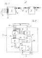
- a communication system 1 is represented in Figure 1 .
- the communication system 1 comprises a master control means 2 that receives control signals from a controller system (not shown) and a slave control means 3.
- the master control means 2 receives signals from the controller system via multipole connection means 4.
- the multipole connection means 4 shown in Figure 1 uses a 25-pin D-type connector 5.
- the master control means 2 is in communication with each slave control means 3 via addressable connection means in the form of a sub-bus, which operates in accordance with the RS485 standard/protocol.
- the master control means 2 has a master sub-bus connector 6 for connecting it, via a sub-bus cable 7, to a slave sub-bus connector 8 on the slave control means 3.
- the master control means 2 forms the master node on a sub-bus (with the cable 7 forming part of the bus) and the slave control means 3 forms the slave node on the bus.
- the slave control system 3 has a further sub-bus connector 9 for connecting it to a further slave control means (not shown).
- addressable connection means may be based on a sub-bus that operates in accordance with other standards such as CAN or LIN depending upon the application of the system.
- slave control means may be added in a "chain-like" arrangement.
- the number of slave control means that may be added is limited by the electrical power that can be supplied via the multipole connection 4 or through subsequent connections, as it is the power received through the connection 4 that allows the subsequent control means to operate.
- the master or slave control means may be adapted to receive their own power supply.
- the master control means 2 and the slave control means 3 are associated with valve islands (not shown).
- the control means 2, 3 control solenoid-actuated pneumatic valves mounted on the valve island.
- the pneumatic valves may be used to actuate production machinery or the like.
- FIG. 2 shows a block diagram of the master control means 2, which is represented by the dashed lines.
- the diagram shows how the multipole signal 4 is used and how the signals are output to the sub-bus connector 6.
- the multipole signal 4 received by the control means 2 comprises twenty-five pins that provide the control signals 10 and a common 0 volts 11, which provides a ground for the system.
- the control signals 10 are received by signal conditioning means 12, which prepares the signals 10 for being received by a microprocessor 15.
- the signal conditioning means 12 reduces the voltage of the signals from typically 24 volts to a voltage that can be reliably interpreted by the microprocessor 15.
- the signal conditioning means outputs a signal 13 that is received by the microprocessor 15.
- the microprocessor 15 interprets the signal and determines whether the valve to be actuated (not shown) is located on the valve island with which the control means 2 is associated or with which the slave control means 3 is associated. If it is determined that the valve to be actuated is controlled by the slave control means 3, the microprocessor 15 prepares the appropriate addressed signal for transmission on the sub-bus 7 of the addressable connection means.
- the output signal 16 is a serial signal to a sub-bus transceiver 17.
- the sub-bus transceiver 17 modifies the signal 16 in accordance with the protocol/standard of the sub-bus (RS485) and then outputs the addressed data signal for transit over the sub-bus at 26.
- the output 26 is connected to the sub-bus connector 6 for transmitting along the sub-bus cable 7.
- the control signals 10 are used to provide power for the components 15, 17 of the master control means 2 and for transmission to the further slave control means 3, via the sub-bus cable 7.
- the outputs 14 are received by a diode array 18.
- the diode array 18 combines the control signals 10 in the nature of an OR-gate to a single 24 volt power output 19.
- the 24 volts output 19 branches into a first line 20 and a second line 21.
- the first line 20 connects to the sub-bus connector 6 to provide power for the subsequent slave control means 3.
- the second line 21 is received by a voltage regulator 22 that regulates the 24 volt input 21 to a voltage suitable for operating the logic of the microprocessor 15 and the sub-bus transceiver 17.
- the voltage regulator 22 has an output 23 that branches into separate lines 24, 25 to supply power to the microprocessor and sub-bus transceiver respectively.
- the outputs from the master control means 2 are output via the sub-bus connector 6.
- the data signal 26 Although only one pin is shown for the data signal 26, there will be as many pins as required by the communication standard used for the addressable connection means.
- a diagram of the slave control means 3 is shown in Figure 3 .
- the slave control means 3 receives the three signals 20, 26 and 27 via the cable 7 and connector 8.
- the data signal 26 is received by a sub-bus transceiver 28, which interprets the signal in accordance with the RS485 standard/protocol.
- the sub-bus transceiver 28 outputs the signal at 29, which is received by a microprocessor 30.
- the microprocessor interprets the signal and if required passes instructions 31 to output means 32.
- the microprocessor interprets the serial data signal 29 from the sub-bus transceiver 28 and, if required, outputs a signal 33 via the output array 32.
- the output 33 from the output means 32 controls the appropriate solenoid valve on the valve island with which the control means 3 is associated.
- the 24 volts input 20 splits when it enters the slave control means 3, one line being received by a voltage regulator 34 and the other by the output means 32.
- the output means uses the 24 volts to actuate the solenoids on the valve island (not shown).
- the voltage regulator 34 as in the master control means 2, has outputs 35 and 36 to provide power for the sub-bus transceiver 28 and the microprocessor 30, respectively.
- the microprocessor 30 of the slave control means 3 has two-way communication with the sub-bus transceiver 28 and thus further slave control means can be attached to data line 26 (the sub-bus) via the second sub-bus connector 9 (shown in Figure 1 ).
- the second sub-bus connector 9 is connected to the sub-bus transceiver 28.
- the controller system passes a multipole signal 4 to the master control means 2 to actuate a specific valve on either of the valve islands associated with control means 2, 3.
- the signal conditioner 12 receives the multipole control signals 10 and outputs the conditioned signals 13.
- the microprocessor 15 of the master control means 2 receives power from the voltage regulator 22 and receives the signals 13.
- the microprocessor 15 determines whether the valve to be actuated is located on the valve island with which it is associated. If so, it passes the appropriate signal to output means (not shown). If the valve is determined to be associated with the slave control means 3, the microprocessor prepares an addressed signal 16 and passes it to the sub-bus transceiver 17.
- the sub-bus transceiver 17 transmits it along the sub-bus cable 7 to the slave control means 3 in accordance with the protocol of the sub-bus.
- the signal is received by the sub-bus transceiver 28 of the slave control means 3.
- the transceiver 28 interprets and then outputs signal 29 to the microprocessor 30 of the slave control means 3.
- the microprocessor 30 processes the signal 29 in accordance with its program to determine if the signal is addressed to it and thus if a valve connected to the slave control means 3 should be actuated. If so, the appropriate signal 31 is sent to the output means 32, which causes the appropriate valve to be actuated. If the microprocessor determines that the signal 29 is not addressed to it, it is ignored.
- the signal 26 is also relayed to any subsequent slave control means 3 by the sub-bus transceiver 28, via the further sub-bus connector 9, and any further slaves (not shown) processes the signal as described above.
- the microprocessors 15, 30 may be pre-programmed or the user, via a RS232 interface or Bluetooth, may set the program, for example.
- the user may be able to program which valve or combination of valves are actuated in response to each multipole input 10.
- valve islands can be controlled from a single 25-pin (or other standard connector) multipole based system.
- a single valve island not to include a complete quota of valves thereon and therefore not all of the pins would be in use.
- a standard multipole system a user may require several valve islands each connected by separate multipole connectors.
- the present invention allows the valves to be spread over a master and several slave valve islands that are controlled via the master control means. This reduces the amount of cabling required and the number of outputs at the controller system. Therefore, the system of the invention has the simplicity and ease of use of a multipole system, while having the flexibility of a Fieldbus system.
- An output means 40 (as shown in Figure 4 ) comprises actuation signal arrangement means 41, 41' and actuation means 42, 42'. Each pair 43, 44 of actuation signal arrangement means 41, 41' and actuation means 42, 42' are associated with a fluid flow control means in the form of a solenoid operated valve (not shown).
- the actuation signal arrangement means 41, 41' comprise a "D" type flip-flop having a power supply line 45, an edge-triggered clock signal input 46, a pre-actuation signal data input 47, 48, a pre-actuation signal data output 49, 50 and a 0 volts line 51.
- the data outputs 49, 50 branch to connect to the associated actuation means 42, 42'.
- the actuation means 42, 42' comprise a "D" type latch. Inputs 52 and 53 to the latches 42, 42' are from outputs 49 and 50 respectively.
- the latches 42, 42' also have a power supply line 45 and 0 volts line 51.
- the latches 42 and 42' are connected to the valves by output lines 54 and 55.
- the latches 42, 42' also have inputs 56 for receiving an actuation signal.
- the output means 40 is of the form of a 2-bit serial latch.
- the clock signal input 46, the pre-actuation signal data input 47 and the edge-triggered actuation signal input 56 are all received from the master or slave microprocessor 15, 30.
- the above inputs are digital and thus take the form of either a "1" or a "0".
- the sequence in which the above signals are applied determines which valves are actuated. For example, to actuate the second valve in the chain a pre-actuation signal of "1" is applied to the input 47 at the same time as a clock pulse at input 46. As will be appreciated, this causes the pre-actuation signal of "1” to appear at output 49 and therefore form the input of the second flip-flop 41' at input 48. During the second clock cycle, the pre-actuation signal is "0". Thus, after the second clock pulse at input 46, there is a pre-actuation signal of "0" at output 49 and the pre-actuation signal of "1" now appears at output 50.
- the microprocessor 15, 30 now outputs an actuation signal to input 56.
- actuation signal As the outputs 49 and 50 form the inputs 52 and 53, after the actuation signal, a "0" will appear at valve output 54 and a “1" will appear at valve output 55.
- the first valve in the chain will not be actuated, as it will receive a "0" signal, while the second valve in the chain will be actuated, as it receives the pre-actuation signal of "1".
- the pre-actuation signal data input of the additional flip-flop/latch pair can be connected to the output 50.
- Further valves can be added in a similar manner.
- this method can be used to actuate any valve in the chain of valves or any combination thereof, as the pre-actuation signals are fed into the chain at input 47 and then "passed through” the flip-flops by the clock signal edge. Once the clock signal has cycled the required number of times and the pre-actuation signals form the input of the appropriate latch 42, 42', the actuation signal is applied to pass the signals to the appropriate valve.
- This method may also be used in a configuration mode to allow the microprocessor to determine how many valves are connected to the valve island with which it is associated.
- the output 50 returns to the microprocessor.
- a pre-actuation signal of "1" is applied at input 47 during the first clock cycle at input 46. After the first clock cycle the pre-actuation signal is kept as "0".
- the microprocessor 15, 30 then counts the number of clock cycles applied at inputs 46 until the pre-actuation signal of "1" returns to it. The number of valves can thus be determined by counting the number of clock pulses applied during this configuration mode.
- each slave control means 3 may pass the information of the number of valves associated with it back to the master control means 2.
- the master control means can then determine which valve is attached to which slave control means 3 and therefore address the appropriate one in response to the multipole signals 10.
Landscapes
- Engineering & Computer Science (AREA)
- Computer Networks & Wireless Communication (AREA)
- Automation & Control Theory (AREA)
- Mechanical Engineering (AREA)
- General Engineering & Computer Science (AREA)
- Fluid Mechanics (AREA)
- Physics & Mathematics (AREA)
- Microelectronics & Electronic Packaging (AREA)
- Signal Processing (AREA)
- Control By Computers (AREA)
- Selective Calling Equipment (AREA)
- Small-Scale Networks (AREA)
- Arrangements For Transmission Of Measured Signals (AREA)
- Programmable Controllers (AREA)
Claims (19)
- Kommunikationssystem, umfassend ein Steuerungssystem, ein Master-Steuermittel (2) und mindestens ein Slave-Steuermittel (3), wobei das Master-Steuermittel (2) und mindestens ein Slave-Steuermittel (3) zum Steuern von Flüssigkeitsregelventilen angeordnet sind, wobei das Steuerungssystem und das Master-Steuermittel (2) über ein Multipolanschlussmittel (4) miteinander verbunden sind, wobei das Master-Steuermittel (2) angepasst ist, ein Multipolsignal über das Multipolanschlussmittel (4) zu empfangen und ein adressiertes Signal an das mindestens eine Slave-Steuermittel (3) über adressierbare Anschlussmittel in Form eines Sub-Busses (7, 17) auszugeben, wobei das Master-Steuermittel (2) einen Mikroprozessor (15) umfasst, der angeordnet ist, um das Multipolsignal zu interpretieren, zu bestimmen, ob das zu betätigende Ventil auf einer Ventilinsel angeordnet ist, mit der das Steuermittel (2) verknüpft ist oder mit der das Slave-Steuermittel (3) verknüpft ist, und, wenn bestimmt wird, dass das zu betätigende Ventil vom Slave-Steuermittel (3) gesteuert wird, ein geeignetes adressiertes Signal für die Übertragung auf dem Sub-Bus (7) des adressierbaren Verbindungsmittels zu erzeugen.
- Kommunikationssystem nach Anspruch 1, bei dem das Steuerungssystem eine speicherprogrammierbare Steuerung (SPS) ist.
- Kommunikationssystem nach Anspruch 1 oder Anspruch 2, bei dem die Master- und Slave-Steuermittel (2, 3) Flüssigkeitsregelventile steuern.
- Kommunikationssystem nach einem der vorhergehenden Ansprüche, bei dem die Master- und Slave-Steuermittel (2, 3) mit Ventilinseln verknüpft sind und auf diesen angeordnete Solenoid-betriebene Ventile steuern.
- Kommunikationssystem nach einem der vorhergehenden Ansprüche, bei dem ein weiteres Slave-Steuermittel (3) in kettenartiger Weise über adressierbare Anschlussmittel (7, 17) an das Kommunikationssystem angeschlossen ist.
- Kommunikationssystem nach einem der vorhergehenden Ansprüche, bei dem die adressierbaren Anschlussmittel (7, 17) auf einem LIN-Standard (LIN = Local Interconnect Network) basieren.
- Kommunikationssystem nach einem der Ansprüche 1 bis 5, bei dem die adressierbaren Anschlussmittel (7, 17) auf dem CAN-Standard (CAN = Controller Area Network) basieren.
- Kommunikationssystem nach einem der Ansprüche 1 bis 5, bei dem die adressierbaren Anschlussmittel (7, 17) auf einem RS485 Standard basieren.
- Kommunikationssystem nach einem der vorhergehenden Ansprüche, bei dem die Master- und Slave-Steuermittel (2, 3) ein Sendeempfangermittel (28) enthalten, um ihnen die Kommunikation unter Einsatz des Protokolls der adressierbaren Anschlußmittel (7, 17) zu ermöglichen.
- Kommunikationssystem nach einem der vorhergehenden Ansprüche, bei dem das Multipolanschlussmittel (4) einen 25-poligen Stecker umfasst.
- Kommunikationssystem nach einem der Ansprüche 1 bis 9, bei dem das Multipolanschlussmittel (4) einen 44-poligen Stecker umfasst.
- Kommunikationssystem nach einem der vorhergehenden Ansprüche, bei dem das Master-Steuermittel (2) einen Mikroprozessor (15) umfasst.
- Kommunikationssystem nach einem der vorhergehenden Ansprüche, bei dem das Slave-Steuermittel (3) einen Mikroprozessor (30) umfasst.
- Kommunikationssystem nach einem der vorhergehenden Ansprüche, bei dem das Master-Steuermittel (2) eine Dipolanordnung (18) enthält, die Energie für das Master-Steuermittel (2) und für die Betätigung der von ihm gesteuerten Vorrichtungen von dem Multipol-Eingangssignal (10) ableitet.
- Kommunikationssystem nach einem der vorhergehenden Ansprüche, bei dem das Slave-Steuermittel (3) Energie von den adressierbaren Anschlussmitteln (7, 17) ableitet.
- Kommunikationssystem nach einem der vorhergehenden Ansprüche, bei dem das Master-Steuermittel (2) ein Signalkonditioniermittel (12) aufweist, um sicherzustellen, dass die von dem Multipolanschlussmittel (4) empfangenen Signale eine für den Empfang der Steuermittel durch den Mikroprozessor (15) geeignete Form aufweisen.
- Kommunikationssystem nach einem der vorhergehenden Ansprüche, bei dem die Master- und Slave-Steuermittel (2, 3) ein Ausgabemittel (32) zur Betätigung des benötigten Ventils aufweisen.
- Kommunikationssystem nach Anspruch 17, bei dem das Ausgabemittel (32) einen Ausgabe-Array-Demultiplexer umfasst.
- Kommunikationssystem nach Anspruch 17, bei dem das Ausgabemittel (32) angepasst ist, ein von den Steuermitteln kommendes serielles Signal zum Steuern des entsprechenden Ventils zu verwenden.
Priority Applications (1)
| Application Number | Priority Date | Filing Date | Title |
|---|---|---|---|
| EP09165276.8A EP2110560A3 (de) | 2005-01-07 | 2005-12-23 | Kommunikationssystem mit einem Steuerungssystem und einem Master-Steuerungsmittel, das über ein mehrpoliges Verbindungsmittel daran angeschlossen ist |
Applications Claiming Priority (2)
| Application Number | Priority Date | Filing Date | Title |
|---|---|---|---|
| GBGB0500223.3A GB0500223D0 (en) | 2005-01-07 | 2005-01-07 | Communication system |
| PCT/GB2005/005074 WO2006072770A1 (en) | 2005-01-07 | 2005-12-23 | Communication system comprising a controller system and a master control means connected via a multipole connection means |
Related Child Applications (3)
| Application Number | Title | Priority Date | Filing Date |
|---|---|---|---|
| EP09165276.8A Division-Into EP2110560A3 (de) | 2005-01-07 | 2005-12-23 | Kommunikationssystem mit einem Steuerungssystem und einem Master-Steuerungsmittel, das über ein mehrpoliges Verbindungsmittel daran angeschlossen ist |
| EP09165276.8A Division EP2110560A3 (de) | 2005-01-07 | 2005-12-23 | Kommunikationssystem mit einem Steuerungssystem und einem Master-Steuerungsmittel, das über ein mehrpoliges Verbindungsmittel daran angeschlossen ist |
| EP09165276.8 Division-Into | 2009-07-13 |
Publications (3)
| Publication Number | Publication Date |
|---|---|
| EP1834447A1 EP1834447A1 (de) | 2007-09-19 |
| EP1834447B1 EP1834447B1 (de) | 2010-10-27 |
| EP1834447B2 true EP1834447B2 (de) | 2015-09-30 |
Family
ID=34203713
Family Applications (2)
| Application Number | Title | Priority Date | Filing Date |
|---|---|---|---|
| EP05821680.5A Not-in-force EP1834447B2 (de) | 2005-01-07 | 2005-12-23 | Kommunikationssystem mit einem steuerungssystem und einem master-kontrollmittel, die durch einen mehrpoligen anschluss verbunden sind |
| EP09165276.8A Withdrawn EP2110560A3 (de) | 2005-01-07 | 2005-12-23 | Kommunikationssystem mit einem Steuerungssystem und einem Master-Steuerungsmittel, das über ein mehrpoliges Verbindungsmittel daran angeschlossen ist |
Family Applications After (1)
| Application Number | Title | Priority Date | Filing Date |
|---|---|---|---|
| EP09165276.8A Withdrawn EP2110560A3 (de) | 2005-01-07 | 2005-12-23 | Kommunikationssystem mit einem Steuerungssystem und einem Master-Steuerungsmittel, das über ein mehrpoliges Verbindungsmittel daran angeschlossen ist |
Country Status (8)
| Country | Link |
|---|---|
| US (1) | US7653442B2 (de) |
| EP (2) | EP1834447B2 (de) |
| JP (2) | JP4625504B2 (de) |
| CN (2) | CN101521612B (de) |
| DE (1) | DE602005024439D1 (de) |
| GB (1) | GB0500223D0 (de) |
| MX (1) | MX2007008191A (de) |
| WO (1) | WO2006072770A1 (de) |
Families Citing this family (15)
| Publication number | Priority date | Publication date | Assignee | Title |
|---|---|---|---|---|
| US7716404B2 (en) * | 2008-02-23 | 2010-05-11 | Aten International Co., Ltd. | Pseudo-full duplex communication using a half duplex communication protocol |
| EP2241765B1 (de) * | 2009-04-17 | 2013-10-09 | HAWE Hydraulik SE | Ventilbatterie mit CAN-Bus Umlaufventil |
| US8601190B2 (en) * | 2011-06-24 | 2013-12-03 | Teco-Westinghouse Motor Company | Providing multiple communication protocols for a control system having a master controller and a slave controller |
| CN103365259B (zh) * | 2012-04-10 | 2016-09-28 | 泰科电子(上海)有限公司 | 控制线路模组、电气设备以及调制解调装置 |
| DE102012021436A1 (de) * | 2012-10-30 | 2014-04-30 | Volkswagen Aktiengesellschaft | Vorrichtung zum assistierenden oder automatischen Führen eines Kraftfahrzeuges |
| US10006557B2 (en) | 2013-03-15 | 2018-06-26 | Asco, L.P. | Valve manifold circuit board with serial communication and control circuit line |
| CA2902643C (en) | 2013-03-15 | 2019-04-02 | Numatics, Incorporated | Valve manifold circuit board with serial communication circuit line |
| DE102013005478B3 (de) | 2013-03-28 | 2014-01-30 | Thomas Magnete Gmbh | Druckregelventil mit elektrischer Ansteuerung |
| CN104238380B (zh) * | 2013-06-06 | 2018-04-27 | 泰科电子(上海)有限公司 | 一种用于电器的智能连接器模块 |
| CN106154071B (zh) * | 2015-04-08 | 2018-12-11 | 国网安徽省电力公司 | 一种检测智能电能表rs485总线故障的装置及方法 |
| US10001786B2 (en) * | 2016-03-22 | 2018-06-19 | Bendix Commercial Vehicle Systems Llc | Solenoid manifold device, controller and method of controlling a solenoid manifold |
| KR101778274B1 (ko) | 2016-03-31 | 2017-09-13 | 강릉원주대학교산학협력단 | 스마트 윈도우 컨트롤러 |
| DE102017106891A1 (de) * | 2017-03-30 | 2018-10-04 | Bürkert Werke GmbH & Co. KG | Ventilinsel |
| DE102017108183A1 (de) * | 2017-04-18 | 2018-10-18 | Bürkert Werke GmbH & Co. KG | Elektronikmodul zum Ankoppeln an eine Modulanordnung und Modulanordnung |
| CN116587256A (zh) * | 2023-07-17 | 2023-08-15 | 江苏新惕姆智能装备有限公司 | 机器人集成夹具用阀岛 |
Citations (6)
| Publication number | Priority date | Publication date | Assignee | Title |
|---|---|---|---|---|
| DE3829034A1 (de) † | 1987-09-14 | 1989-03-16 | Kuroda Gauge Mfg | Steuervorrichtung fuer rohrverzweigungs-magnetventile |
| WO1994004831A1 (de) † | 1992-08-19 | 1994-03-03 | Festo Kg | Elektro-pneumatische steuereinrichtung |
| JPH0742865A (ja) † | 1993-07-30 | 1995-02-10 | Olympus Optical Co Ltd | 電磁弁制御システム |
| DE29821410U1 (de) † | 1998-10-19 | 1999-02-11 | Mannesmann Ag | Scheibenförmige Ventilanordnung |
| WO1999054632A1 (de) † | 1998-04-20 | 1999-10-28 | Bürkert Werke GmbH & Co. | Modulares elektrofluidisches baukastensystem |
| WO2001029431A1 (en) † | 1999-10-20 | 2001-04-26 | Parker Hannifin Plc | Fluid control system |
Family Cites Families (45)
| Publication number | Priority date | Publication date | Assignee | Title |
|---|---|---|---|---|
| US3591850A (en) * | 1969-06-27 | 1971-07-06 | Fmc Corp | Irrigation control system |
| FR2547075B1 (fr) * | 1983-06-03 | 1986-03-28 | Telemecanique Electrique | Procede et dispositif pour la protection et le controle de la transmission des informations entre l'unite centrale d'un automate programmable et les capteurs et/ou les actionneurs du processus commande |
| FR2547076B1 (fr) * | 1983-06-03 | 1986-01-03 | Telemecanique Electrique | Procede et dispositif pour le controle de la transmission des informations entre l'unite centrale d'un automate programmable et les circuits d'entree/sortie raccordes aux capteurs et/ou aux actionneurs du processus commande |
| NZ219439A (en) * | 1987-02-27 | 1990-02-26 | Gec New Zealand Ltd | Ac motor speed controller with controlled current inverter |
| DE3807149C2 (de) * | 1988-03-04 | 1996-08-29 | Siemens Ag | Verfahren zum Feststellen des Auftretens derselben Teilnehmereinrichtungsadresse für eine Teilnehmereinrichtung in einem ringförmigen Kommunikationsnetz |
| EP0345493B1 (de) * | 1988-06-08 | 1994-03-09 | Landis & Gyr Technology Innovation AG | Anordnung zur Überwachung, Steuerung und Regelung einer betriebstechnischen Anlage eines Gebäudeautomationssystems |
| DE3835755A1 (de) * | 1988-10-20 | 1990-04-26 | Hemscheidt Maschf Hermann | Elektrohydraulische steuerungseinrichtung fuer hydraulische schreitausbau-einheiten |
| US6055213A (en) * | 1990-07-09 | 2000-04-25 | Baker Hughes Incorporated | Subsurface well apparatus |
| US5579283A (en) * | 1990-07-09 | 1996-11-26 | Baker Hughes Incorporated | Method and apparatus for communicating coded messages in a wellbore |
| US5226494A (en) * | 1990-07-09 | 1993-07-13 | Baker Hughes Incorporated | Subsurface well apparatus |
| US5343963A (en) * | 1990-07-09 | 1994-09-06 | Bouldin Brett W | Method and apparatus for providing controlled force transference to a wellbore tool |
| US5247450A (en) * | 1991-02-12 | 1993-09-21 | Vhc Ltd. | Electronic timing system for glassware-forming machines |
| IT1252582B (it) * | 1991-12-23 | 1995-06-19 | Nisva Srl | Impianto di alimentazione e controllo particolarmente per attuatori fluidici e simili |
| US5249140A (en) * | 1991-05-07 | 1993-09-28 | Vickers, Incorporated | Electrohydraulic distributed control system with identical master and slave controllers |
| US5331619A (en) * | 1992-02-19 | 1994-07-19 | Bradley Corporation | Programmable control system for gas and liquid dispensing devices |
| JPH06224913A (ja) * | 1992-05-14 | 1994-08-12 | Digital:Kk | データ伝送用アダプタおよびデータ伝送システム |
| GB2302607B (en) * | 1995-02-10 | 2000-06-28 | Baker Hughes Inc | Method and apparatus for remote control of wellbore end devices |
| DE19629868A1 (de) * | 1996-07-24 | 1998-02-05 | Kloeckner Moeller Gmbh | Verfahren zur Übertragung binärer Daten und Schnittstellenbausteine zur Durchführung des Verfahrens |
| JPH1063375A (ja) * | 1996-08-21 | 1998-03-06 | Mitsubishi Electric Corp | 通信システム |
| KR100202706B1 (ko) * | 1996-10-05 | 1999-06-15 | 이종수 | 피엘씨 리모트 시스템의 기동시간 동기화 및 비상상태 출력 제어방법 |
| JP3339786B2 (ja) * | 1996-12-02 | 2002-10-28 | オークマ株式会社 | 環状通信路におけるタイマー同期化装置および初期化方法 |
| JP3054632B2 (ja) * | 1997-01-27 | 2000-06-19 | シーケーディ株式会社 | 電磁弁制御システム |
| DE59809526D1 (de) * | 1997-04-10 | 2003-10-16 | Moeller Gmbh | Busfähige elektrische Koppeleinheit |
| US6053198A (en) * | 1997-12-01 | 2000-04-25 | Numatics, Incorporated | Solenoid valve control system |
| JP2000116940A (ja) * | 1998-10-15 | 2000-04-25 | Seta Corp | 双方向通信型ゲームシステム |
| JP2000196700A (ja) * | 1998-12-24 | 2000-07-14 | Smc Corp | 調歩同期式データ伝送方法 |
| IT1311253B1 (it) | 1999-10-26 | 2002-03-04 | Fluido Sistem S R L | Dispositivo di comando integrato per automazioni industriali. |
| EP1100152A3 (de) | 1999-11-13 | 2005-03-02 | Weidmüller Interface GmbH & Co. | Verteiler und Verteilersystem |
| DE10011127C2 (de) * | 2000-03-09 | 2003-03-13 | Ifm Electronic Gmbh | Elektronisches Gerät |
| US6535043B2 (en) * | 2000-05-26 | 2003-03-18 | Lattice Semiconductor Corp | Clock signal selection system, method of generating a clock signal and programmable clock manager including same |
| US6734020B2 (en) * | 2001-03-07 | 2004-05-11 | Applied Materials, Inc. | Valve control system for atomic layer deposition chamber |
| EP1396771B1 (de) * | 2001-05-31 | 2016-02-17 | Omron Corporation | Slave-einheiten und netzwerksystem, sowie slaveverarbeitungsverfahren und informationssammelverfahren |
| FR2829655B1 (fr) * | 2001-09-10 | 2003-12-26 | Digigram | Systeme de transmission de donnees audio, entre un module maitre et des modules esclaves, par l'intermediaire d'un reseau de communication numerique |
| US7366115B2 (en) * | 2001-12-13 | 2008-04-29 | Ami Semiconductor Belgium Bvba | Multiplex transmission system with in-circuit addressing |
| JP2003337793A (ja) * | 2002-03-15 | 2003-11-28 | Omron Corp | ネットワークシステム及びネットワークシステムの通信方法 |
| CN1375802A (zh) * | 2002-04-17 | 2002-10-23 | 吴远彪 | 多个电器单元的单线传输控制装置 |
| US7292945B2 (en) * | 2002-07-19 | 2007-11-06 | Entegris, Inc. | Fluid flow measuring and proportional fluid flow control device |
| DE20301676U1 (de) * | 2003-02-04 | 2004-03-11 | Heye International Gmbh | Elektronische Steuerung von Glasformmaschinen |
| EP1625482A2 (de) * | 2003-04-11 | 2006-02-15 | Strattec Security Corporation | Zündvorrichtung und -verfahren |
| US6998807B2 (en) * | 2003-04-25 | 2006-02-14 | Itt Manufacturing Enterprises, Inc. | Active sensing and switching device |
| DE10327013A1 (de) * | 2003-06-12 | 2004-12-30 | Endress + Hauser Wetzer Gmbh + Co Kg | Steckkupplungssystem zum lösbaren elektrischen Verbinden eines programmierbaren Feldgeräts mit einem Feldbus oder mit einem Programmiergerät |
| DE10328906A1 (de) * | 2003-06-26 | 2005-01-13 | Endress + Hauser Process Solutions Ag | Feldbusverteilereinheit |
| CN1278885C (zh) * | 2003-09-18 | 2006-10-11 | 上海交通大学 | 超级电容电车充电控制系统 |
| JP2005141532A (ja) * | 2003-11-07 | 2005-06-02 | Kawasaki Microelectronics Kk | システムデバッグ装置 |
| US7307519B2 (en) * | 2005-07-12 | 2007-12-11 | Yazaki Corporation | Communication system and PLC network |
-
2005
- 2005-01-07 GB GBGB0500223.3A patent/GB0500223D0/en not_active Ceased
- 2005-12-23 DE DE602005024439T patent/DE602005024439D1/de active Active
- 2005-12-23 MX MX2007008191A patent/MX2007008191A/es active IP Right Grant
- 2005-12-23 EP EP05821680.5A patent/EP1834447B2/de not_active Not-in-force
- 2005-12-23 EP EP09165276.8A patent/EP2110560A3/de not_active Withdrawn
- 2005-12-23 US US11/813,496 patent/US7653442B2/en not_active Expired - Fee Related
- 2005-12-23 WO PCT/GB2005/005074 patent/WO2006072770A1/en active Application Filing
- 2005-12-23 CN CN2009101282413A patent/CN101521612B/zh not_active Expired - Fee Related
- 2005-12-23 JP JP2007548893A patent/JP4625504B2/ja not_active Expired - Fee Related
- 2005-12-23 CN CN200580046169XA patent/CN101099343B/zh not_active Expired - Fee Related
-
2010
- 2010-09-08 JP JP2010200538A patent/JP4875197B2/ja not_active Expired - Fee Related
Patent Citations (6)
| Publication number | Priority date | Publication date | Assignee | Title |
|---|---|---|---|---|
| DE3829034A1 (de) † | 1987-09-14 | 1989-03-16 | Kuroda Gauge Mfg | Steuervorrichtung fuer rohrverzweigungs-magnetventile |
| WO1994004831A1 (de) † | 1992-08-19 | 1994-03-03 | Festo Kg | Elektro-pneumatische steuereinrichtung |
| JPH0742865A (ja) † | 1993-07-30 | 1995-02-10 | Olympus Optical Co Ltd | 電磁弁制御システム |
| WO1999054632A1 (de) † | 1998-04-20 | 1999-10-28 | Bürkert Werke GmbH & Co. | Modulares elektrofluidisches baukastensystem |
| DE29821410U1 (de) † | 1998-10-19 | 1999-02-11 | Mannesmann Ag | Scheibenförmige Ventilanordnung |
| WO2001029431A1 (en) † | 1999-10-20 | 2001-04-26 | Parker Hannifin Plc | Fluid control system |
Also Published As
| Publication number | Publication date |
|---|---|
| DE602005024439D1 (de) | 2010-12-09 |
| US20080208366A1 (en) | 2008-08-28 |
| CN101521612B (zh) | 2012-10-10 |
| EP2110560A3 (de) | 2013-10-09 |
| JP4625504B2 (ja) | 2011-02-02 |
| CN101099343A (zh) | 2008-01-02 |
| JP2008527771A (ja) | 2008-07-24 |
| CN101521612A (zh) | 2009-09-02 |
| EP1834447A1 (de) | 2007-09-19 |
| WO2006072770A1 (en) | 2006-07-13 |
| US7653442B2 (en) | 2010-01-26 |
| EP2110560A2 (de) | 2009-10-21 |
| MX2007008191A (es) | 2007-08-22 |
| GB0500223D0 (en) | 2005-02-16 |
| JP2011045094A (ja) | 2011-03-03 |
| JP4875197B2 (ja) | 2012-02-15 |
| EP1834447B1 (de) | 2010-10-27 |
| CN101099343B (zh) | 2012-01-25 |
Similar Documents
| Publication | Publication Date | Title |
|---|---|---|
| EP1834447B2 (de) | Kommunikationssystem mit einem steuerungssystem und einem master-kontrollmittel, die durch einen mehrpoligen anschluss verbunden sind | |
| US10127163B2 (en) | Control device for controlling a safety device, and use of an IO link for transmission of a safety protocol to a safety device | |
| CN101652270B (zh) | 车辆通信系统与用于操作通信系统的方法 | |
| CN101523310B (zh) | 用于冗余控制子设备的方法及系统 | |
| CN103827759B (zh) | 配置通信接口模块的方法和控制或自动化系统 | |
| US10430359B2 (en) | Use of an IO link for linking field devices | |
| US20030200323A1 (en) | Coupling apparatus for the coupling of devices to a bus system | |
| EP1653363A1 (de) | Knoten für ein Bus-Netzwerk, Bus-Netzwerk und Verfahren zum Konfigurieren des Netzwerks | |
| JP7040841B2 (ja) | セグメント化された制御装置 | |
| CN102035898B (zh) | 自动化设备与数据处理设备数据通信的方法和接口转换器 | |
| EP2161638B2 (de) | Automatisierungssystem, Gerät zur Verwendung in einem Automatisierungssystem und Verfahren zum Betreiben eines Automatisierungssystems | |
| CA3000640A1 (en) | A valve manifold serially mounted to a distributed control system assembly | |
| CN107113211A (zh) | 一种包含有服务模块的功能连接单元 | |
| CN106027584B (zh) | 设定方法、通信设备及其网络系统 | |
| DE102017213365B4 (de) | Kommunikationsvorrichtung, System und Verfahren | |
| CN108873769A (zh) | 自动化系统和运行方法 | |
| CN100458752C (zh) | 集成电路用的总线系统 | |
| US20140031955A1 (en) | Connecting device, system and method for signal transmission between a control center and at least one field device in an industrial installation | |
| JP2011211855A (ja) | サーボ制御装置およびモーションコントロールシステム | |
| DE102007015203A1 (de) | Drahtloses Automatisierungssystem mit lokaler Verarbeitung | |
| Young | A fieldbus approach to robotic systems reconfiguration | |
| KR20000067694A (ko) | 디지털 직렬제어 공압 솔레노이드 밸브 제어시스템 | |
| JP2021190968A (ja) | 通信システム | |
| WO1996018136A1 (en) | Arrangement for components included in mobile hydraulic equipment | |
| CN113348648A (zh) | 用于串行总线系统的用户站的发送/接收装置和用于串行总线系统中的通信的方法 |
Legal Events
| Date | Code | Title | Description |
|---|---|---|---|
| PUAI | Public reference made under article 153(3) epc to a published international application that has entered the european phase |
Free format text: ORIGINAL CODE: 0009012 |
|
| 17P | Request for examination filed |
Effective date: 20070613 |
|
| AK | Designated contracting states |
Kind code of ref document: A1 Designated state(s): AT BE BG CH CY CZ LI |
|
| RBV | Designated contracting states (corrected) |
Designated state(s): CH CZ DE FR GB IT LI |
|
| RBV | Designated contracting states (corrected) |
Designated state(s): CH CZ DE FR GB IT LI |
|
| DAX | Request for extension of the european patent (deleted) | ||
| RBV | Designated contracting states (corrected) |
Designated state(s): CH CZ DE FR GB IT LI |
|
| 17Q | First examination report despatched |
Effective date: 20080521 |
|
| GRAP | Despatch of communication of intention to grant a patent |
Free format text: ORIGINAL CODE: EPIDOSNIGR1 |
|
| GRAS | Grant fee paid |
Free format text: ORIGINAL CODE: EPIDOSNIGR3 |
|
| GRAA | (expected) grant |
Free format text: ORIGINAL CODE: 0009210 |
|
| AK | Designated contracting states |
Kind code of ref document: B1 Designated state(s): CH CZ DE FR GB IT LI |
|
| REG | Reference to a national code |
Ref country code: GB Ref legal event code: FG4D |
|
| REG | Reference to a national code |
Ref country code: CH Ref legal event code: EP |
|
| REF | Corresponds to: |
Ref document number: 602005024439 Country of ref document: DE Date of ref document: 20101209 Kind code of ref document: P |
|
| REG | Reference to a national code |
Ref country code: CH Ref legal event code: NV Representative=s name: MOINAS & SAVOYE SA |
|
| PLBI | Opposition filed |
Free format text: ORIGINAL CODE: 0009260 |
|
| PLAX | Notice of opposition and request to file observation + time limit sent |
Free format text: ORIGINAL CODE: EPIDOSNOBS2 |
|
| 26 | Opposition filed |
Opponent name: FESTO AG & CO. KG Effective date: 20110727 |
|
| REG | Reference to a national code |
Ref country code: DE Ref legal event code: R026 Ref document number: 602005024439 Country of ref document: DE Effective date: 20110727 |
|
| PLAF | Information modified related to communication of a notice of opposition and request to file observations + time limit |
Free format text: ORIGINAL CODE: EPIDOSCOBS2 |
|
| PLBB | Reply of patent proprietor to notice(s) of opposition received |
Free format text: ORIGINAL CODE: EPIDOSNOBS3 |
|
| REG | Reference to a national code |
Ref country code: DE Ref legal event code: R082 Ref document number: 602005024439 Country of ref document: DE Representative=s name: VOSSIUS & PARTNER, DE Ref country code: DE Ref legal event code: R082 Ref document number: 602005024439 Country of ref document: DE Representative=s name: VOSSIUS & PARTNER PATENTANWAELTE RECHTSANWAELT, DE |
|
| PLAB | Opposition data, opponent's data or that of the opponent's representative modified |
Free format text: ORIGINAL CODE: 0009299OPPO |
|
| RIC2 | Information provided on ipc code assigned after grant |
Ipc: H05K 7/14 20060101ALI20150113BHEP Ipc: F15B 13/08 20060101AFI20150113BHEP Ipc: H04L 12/40 20060101ALI20150113BHEP Ipc: H04L 12/403 20060101ALI20150113BHEP |
|
| R26 | Opposition filed (corrected) |
Opponent name: FESTO AG & CO. KG Effective date: 20110727 |
|
| PUAH | Patent maintained in amended form |
Free format text: ORIGINAL CODE: 0009272 |
|
| STAA | Information on the status of an ep patent application or granted ep patent |
Free format text: STATUS: PATENT MAINTAINED AS AMENDED |
|
| 27A | Patent maintained in amended form |
Effective date: 20150930 |
|
| AK | Designated contracting states |
Kind code of ref document: B2 Designated state(s): CH CZ DE FR GB IT LI |
|
| REG | Reference to a national code |
Ref country code: CH Ref legal event code: AELC Ref country code: DE Ref legal event code: R102 Ref document number: 602005024439 Country of ref document: DE |
|
| REG | Reference to a national code |
Ref country code: FR Ref legal event code: PLFP Year of fee payment: 11 |
|
| REG | Reference to a national code |
Ref country code: CH Ref legal event code: PFA Owner name: NORGREN LIMITED, GB Free format text: FORMER OWNER: NORGREN LIMITED, GB |
|
| REG | Reference to a national code |
Ref country code: FR Ref legal event code: PLFP Year of fee payment: 12 |
|
| REG | Reference to a national code |
Ref country code: FR Ref legal event code: PLFP Year of fee payment: 13 |
|
| PGFP | Annual fee paid to national office [announced via postgrant information from national office to epo] |
Ref country code: DE Payment date: 20171211 Year of fee payment: 13 Ref country code: FR Payment date: 20171221 Year of fee payment: 13 |
|
| PGFP | Annual fee paid to national office [announced via postgrant information from national office to epo] |
Ref country code: GB Payment date: 20171221 Year of fee payment: 13 Ref country code: CH Payment date: 20171220 Year of fee payment: 13 |
|
| PGFP | Annual fee paid to national office [announced via postgrant information from national office to epo] |
Ref country code: IT Payment date: 20171221 Year of fee payment: 13 |
|
| PGFP | Annual fee paid to national office [announced via postgrant information from national office to epo] |
Ref country code: CZ Payment date: 20181213 Year of fee payment: 14 |
|
| REG | Reference to a national code |
Ref country code: DE Ref legal event code: R119 Ref document number: 602005024439 Country of ref document: DE |
|
| REG | Reference to a national code |
Ref country code: CH Ref legal event code: PL |
|
| GBPC | Gb: european patent ceased through non-payment of renewal fee |
Effective date: 20181223 |
|
| PG25 | Lapsed in a contracting state [announced via postgrant information from national office to epo] |
Ref country code: DE Free format text: LAPSE BECAUSE OF NON-PAYMENT OF DUE FEES Effective date: 20190702 Ref country code: FR Free format text: LAPSE BECAUSE OF NON-PAYMENT OF DUE FEES Effective date: 20181231 Ref country code: IT Free format text: LAPSE BECAUSE OF NON-PAYMENT OF DUE FEES Effective date: 20181223 |
|
| PG25 | Lapsed in a contracting state [announced via postgrant information from national office to epo] |
Ref country code: GB Free format text: LAPSE BECAUSE OF NON-PAYMENT OF DUE FEES Effective date: 20181223 Ref country code: CH Free format text: LAPSE BECAUSE OF NON-PAYMENT OF DUE FEES Effective date: 20181231 Ref country code: LI Free format text: LAPSE BECAUSE OF NON-PAYMENT OF DUE FEES Effective date: 20181231 |
|
| PG25 | Lapsed in a contracting state [announced via postgrant information from national office to epo] |
Ref country code: CZ Free format text: LAPSE BECAUSE OF NON-PAYMENT OF DUE FEES Effective date: 20191223 |