EP1829809A1 - Fahrtreppe mit Führungsmitteln - Google Patents
Fahrtreppe mit Führungsmitteln Download PDFInfo
- Publication number
- EP1829809A1 EP1829809A1 EP07103244A EP07103244A EP1829809A1 EP 1829809 A1 EP1829809 A1 EP 1829809A1 EP 07103244 A EP07103244 A EP 07103244A EP 07103244 A EP07103244 A EP 07103244A EP 1829809 A1 EP1829809 A1 EP 1829809A1
- Authority
- EP
- European Patent Office
- Prior art keywords
- escalator
- emergency guide
- guide hook
- area
- emergency
- Prior art date
- Legal status (The legal status is an assumption and is not a legal conclusion. Google has not performed a legal analysis and makes no representation as to the accuracy of the status listed.)
- Granted
Links
- 230000015572 biosynthetic process Effects 0.000 claims abstract description 6
- 239000002184 metal Substances 0.000 claims description 5
- 230000003993 interaction Effects 0.000 description 4
- 238000004519 manufacturing process Methods 0.000 description 2
- 239000004677 Nylon Substances 0.000 description 1
- 238000013016 damping Methods 0.000 description 1
- 230000001419 dependent effect Effects 0.000 description 1
- 238000011161 development Methods 0.000 description 1
- 230000018109 developmental process Effects 0.000 description 1
- 238000009434 installation Methods 0.000 description 1
- 229920001778 nylon Polymers 0.000 description 1
- 230000010355 oscillation Effects 0.000 description 1
- 239000004033 plastic Substances 0.000 description 1
- 239000005060 rubber Substances 0.000 description 1
Images


Classifications
-
- B—PERFORMING OPERATIONS; TRANSPORTING
- B66—HOISTING; LIFTING; HAULING
- B66B—ELEVATORS; ESCALATORS OR MOVING WALKWAYS
- B66B23/00—Component parts of escalators or moving walkways
- B66B23/08—Carrying surfaces
-
- B—PERFORMING OPERATIONS; TRANSPORTING
- B66—HOISTING; LIFTING; HAULING
- B66B—ELEVATORS; ESCALATORS OR MOVING WALKWAYS
- B66B23/00—Component parts of escalators or moving walkways
- B66B23/14—Guiding means for carrying surfaces
-
- B—PERFORMING OPERATIONS; TRANSPORTING
- B66—HOISTING; LIFTING; HAULING
- B66B—ELEVATORS; ESCALATORS OR MOVING WALKWAYS
- B66B23/00—Component parts of escalators or moving walkways
- B66B23/08—Carrying surfaces
- B66B23/12—Steps
Definitions
- the invention relates to an escalator with an endless formation of successive stages according to claim 1.
- Escalators often referred to as escalators, have an endless chain of successive steps that can carry people or luggage up or down.
- Guide rails move the steps to the desired position.
- the rollers and guide rails serve to intercept vertically directed forces, for example when entering a step.
- escalators typically include emergency guidance systems.
- the emergency guidance systems require various parts that must be manufactured and fastened.
- the production of emergency management is relatively expensive.
- the object of the invention is seen to propose a novel escalator to avoid the disadvantages of the prior art, which manages without the emergency management systems previously required. It should be reduced especially the assembly effort and assembly costs.
- each step an emergency guide hook is mounted in the area of the front surface or riser such that the emergency guide hook of a higher level supports itself against a part of a cheek of the next underlying step if the step is eccentrically loaded in the area of the tread.
- each step is provided with an emergency guide hook, which is arranged so that the step support each other if there is an eccentric load.
- the mounting is much easier since the emergency guide hook can already be preassembled on the step. So it requires no complex installation and assembly of the individual elements of the emergency guidance system, as in previous escalators.
- the emergency guide hooks can also be cast with the step.
- the emergency guide hook is cheap to manufacture, especially if it is provided as a stamped part made of sheet metal.
- the emergency guide hook is seated directly on the axis of one of the rollers present on the step. This simplifies the assembly.
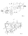
- Fig. 1 shows a conventional escalator 1 connecting a lower level E1 to an upper level E2.
- the escalator has an endless formation of successive stages 3, but only partially shown in FIG are.
- the escalator 1 has, as usual, as side boundaries in the lower part base plates 2.1 (see Fig. 3) and in the upper part of a stationary balustrade 2, on which at the top generally together with the endless formation of stages 3 movable handrail 2.2 is arranged.
- Each step 3 has a tread surface 3.1, a front surface or riser 3.3 and on each side of a sideways cheek 3.4.
- Fig. 2 an inventive stage 3 is shown. In this illustration, one of the lateral cheeks is almost in the plane of the drawing. The second side cheek 3.4 can only be seen from the inside of the steps.
- two laterally outwardly projecting rollers 7 and 8 are provided, which are guided along the laterally mounted, obliquely running rails 5, 6 of the escalator 1 and supported.
- conventional escalators 1 In order to prevent the tilting of a single step 3 when it is eccentrically loaded, for example by a load on the tread surface 3.1, conventional escalators 1 typically have two emergency guide rails 9.
- the emergency guide assembly is relatively expensive and the emergency guide requires many different parts 9, 10, 11, 12, which must be manufactured and delivered.
- Fig. 3 is a section through a conventional escalator 1 is shown transversely to the direction of travel. Based on this figure will be briefly explained how the usual today emergency management is constructed. In addition, other elements of the escalator 1, which are also present in an inventive escalator 1.
- the escalator 1 is mounted in a truss whose various elements are marked in Fig. 3 by the reference numeral 4.
- the aforementioned feed rails 5 and return rails 6 are attached.
- the feed rails 5 have an L-shape in cross-section and thereby define two different levels.
- the rollers 7 and 8 are shown in black in Fig. 3 to better lift them out.
- the feed rails 5 serve as a vertical support for the steps 3 and take on the one hand vertically directed forces and on the other hand lead the steps 3 on the framework 4 up or down (depending on the direction of movement).
- the vertical distance between the upper running plane and the lower running plane is chosen to be relatively small in the inclined area of the escalator 1 so that the steps 3 are rotated or pivoted to the normal position and guided stably. In the normal position, the vertical center distance VA1 between the outer rollers 7 and the inner rollers 8 is small, as indicated on the left side of FIG.
- rollers 7, 8 on each side of a stage 3 are each offset from one another, in order to guide the steps 3 stably along the inclined rails 5, 6 can.
- the return rails 6 also have an upper run level 6.1 and a lower run level 6.2.
- the spacing of these running planes 6.1 and 6.2 is much greater and the steps 3 are suspended in the so-called return area (see Fig. 1), i. with the tread surface 3.1 facing down, fed back.
- the vertical center distance VA2 between the outer rollers 7 and the inner rollers 8 is much greater in the return area than the vertical center distance VA1 in the flow, as indicated on the right side of FIG.
- Each stage 3 has a step body or step body designed to give stability to stage 3 and carry or connect various elements.
- the tread surface 3.1 and the front surface or riser 3.3 Connected to the step body are the tread surface 3.1 and the front surface or riser 3.3.
- the step body comprises two lateral cheeks 3.4, which are formed by a kind of open frame.
- the open frame has an elongated step spar 3.2 in the lower area.
- Starting from the step bar 3.2 extend in the illustration shown front struts 3.4 and 3.5 rear struts upwards. These struts 3.4, 3.5 in turn are connected to spars 3.6 on which the tread surface 3.1 rests.
- the two cheeks are connected by the wheel axle or a stepped axle 7.1.
- the front surface or riser 3.3 runs between the cheeks 3.4.
- the step rail extends substantially parallel to a predetermined by the inclined rails (5) direction when the corresponding stage (3) is located in a lead-in area of the escalator (1).
- the deviation can be ⁇ 10 degrees.
- an emergency guide hook 13 is now mounted at least in the region of one of the cheeks, which is shown in FIG Example substantially perpendicular to the cheek defined plane protrudes inward. If the stage 3 is now eccentrically loaded (as indicated by the arrow F), the result is a tilting movement of the stage 3, which is represented by the rotary arrow D. The emergency guide hook 13 moves in this case slightly up and forward, as indicated schematically by the arrow A.
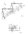
- FIG. 4 shows details of a further embodiment according to the invention in a schematic side view.
- the obliquely extending feed rails 5 are shown and there are two successive stages 3 can be seen.
- the rollers 7 run on upper run levels in the track 5, as described.
- the same reference numerals are used as in the previous figures. An explanation of the elements already described is therefore unnecessary.
- the emergency guide hook 13 is located in the extension of the axis of the roller 8 and is arranged inside and directed outwards (viewed from the cheek).
- FIG. 5 shows that the emergency guide hook 13 may, for example, be a sheet metal stamped and bent part which bears against the step rail 3.2 with a vertical surface. This vertical surface has a hole or a slit for screwing the emergency guide hook 13 to the axis of the roller 8. Furthermore, the emergency guide hook 13 has a contact area which is designed to interact with the step body or step rail 3.2 of the next stage 3 in the event of eccentric loading. As shown in FIG.
- this contact area may have a surface area (horizontal area) which is perpendicular to the vertical area.
- the contact area may also have a different oriented surface.
- the area 14 characterized by a circle, it comes in an emergency to the described interaction or leaning and support between two adjacent stages 3. This interaction causes the eccentrically loaded front first stage 3 via their emergency guide hook 13 against the step body or Stair handle 3.2 of the adjacent rear stage 3 is supported and thereby tilting of the front first stage 3 is stopped or prevented.
- FIG. 6 It can be seen in Fig. 6, the opposite cheek from the inside. The figure is, unlike in Fig. 4, not shown at an angle. In other words the image has been rotated so that the feed rail 5 is horizontal. Of the rollers 7 and 8, only the outlines are shown. On the visible inner side of the cheek, respectively the step spar 3.2, the emergency guide hook 13 is fastened with the nut 15 and an optional screw lock 16 on the axis of the roller 8. The vertical area 13.1 of the emergency guide hook 13 is now in the plane of the drawing.
- the contact area or surface area 13.2 is obliquely set in the embodiment shown and protrudes perpendicularly out of the plane of the drawing, ie the contact area 13.2 points inwards from this cheek.
- area 14 indicated by a circle, in case of emergency mechanical interaction with the next stage 3 occurs.
- FIG. 7 shows a further special embodiment of an emergency guide hook 13 according to the invention.
- the emergency guide hook 13 sits in the extension of the axis or central axis 8.1 of the roller 8 (the roller 8 is not shown) and is directed outwards (viewed from the step spar 3.2 from the right).
- the emergency guide hook 13 is fastened with a nut 15 and an optional screw lock 16 on the axis or central axis 8.1 of the roller 8. That is, a vertical portion 13.1 of the emergency guide hook 13 is flat against the step spar 3.2.
- the contact area 13.2 is designed differently in the example shown. In this area 13.2 sits a buffer element 13.3 (for example, made of rubber, nylon or plastic, PA, PU, POM). This element can be screwed to the emergency guide hook 13, for example by means of a hex screw and nut 13.4.
- This type of embodiment has the advantage that the interaction is damped. By a suitable choice or hardness of the buffer element 13.3, the damping can be adjusted.
- a spring element can be used accordingly.
- the embodiments with buffer or spring element 13.3 have the advantage that they prevent rocking or oscillation of the steps 3 or of the step belt even in normal operation.
Landscapes
- Escalators And Moving Walkways (AREA)
- Emergency Lowering Means (AREA)
- Types And Forms Of Lifts (AREA)
- Steps, Ramps, And Handrails (AREA)
Abstract
Description
- Die Erfindung betrifft eine Fahrtreppe mit einer Endlos-Formation von aufeinanderfolgenden Stufen gemäss Anspruch 1.
- Fahrtreppen, häufig auch als Rolltreppen bezeichnet, weisen eine Endlosekette von aufeinanderfolgenden Stufen auf, die Personen oder Gepäckstücke auf- bzw. abwärts befördern können. An den Stufen sind seitwärts gerichtete Rollen vorhanden, die auf Laufschienen laufen. Durch Führungsschienen werden die Stufen in die gewünschte Lage gebracht. Ausserdem dienen die Rollen samt Führungsschienen dazu, um vertikal gerichtete Kräfte, zum Beispiel beim Betreten einer Stufe, abzufangen.
- Um das Kippen einer einzelnen Stufe zu verhindern, wenn diese zum Beispiel exzentrisch belastet wird, weisen Fahrtreppen typischerweise Notführungssysteme auf. Die Notführungssysteme benötigen verschiedene Teile, die hergestellt und befestigt werden müssen. Ausserdem ist die Herstellung der Notführung relativ aufwendig.
- Die Aufgabe der Erfindung wird darin gesehen, zur Vermeidung der Nachteile des Standes der Technik eine neuartige Fahrtreppe vorzuschlagen, die ohne die bisher erforderlichen Notführungssysteme auskommt. Es soll vor allem der Montageaufwand und Zusammenbauaufwand reduziert werden.
- Die Lösung dieser Aufgabe erfolgt erfindungsgemäss durch die Merkmale des kennzeichnenden Teils des Anspruchs 1.
- Gemäss Erfindung wird an jeder Stufe ein Notführungshaken so im Bereich der Frontfläche bzw. der Setzstufe angebracht, dass der Notführungshaken einer höher liegenden Stufe sich gegen einen Teil einer Wange der nächsten unterhalb liegenden Stufe abstützt, falls die Stufe im Bereich der Trittfläche exzentrisch belastet wird. Mit anderen Worten ausgedrückt wird jede Stufe mit einem Notführungshaken versehen, der so angeordnet ist, dass die Stufe sich gegeneinander abstützen falls es zu eine aussermittigen Belastung kommt.
- Es ist ein Vorteil dieser Erfindung, dass die Montage sehr viel einfacher ist, da der Notführungshaken bereits an der Stufe vormontiert werden kann. Es bedarf also keiner aufwendigen Montage und Zusammenbauen der einzelnen Elemente des Notführungssystems, wie bei bisherigen Fahrtreppen. Alternativ können auch die Notführungshaken mit der Stufe mit gegossen werden.
- Ausserdem ist der Notführungshaken an sich günstig herzustellen, vor allem dann, wenn er als Stanzteil aus Blech bereitgestellt wird.
- In einer gegenwärtig bevorzugten Ausführungsform der Erfindung sitzt der Notführungshaken direkt auf der Achse einer der an der Stufe vorhandenen Rollen. Dies vereinfacht die Montage.
- Bevorzugte Weiterbildungen der neuen Einrichtung sind durch die abhängigen Ansprüche definiert.
- Weitere Einzelheiten und Vorteile der Erfindung werden im Folgenden an Hand von Ausführungsbeispielen und mit Bezug auf die Zeichnung erläutert. Es zeigen:
- Fig. 1
- eine Fahrtreppe mit einer Einrichtung nach der Erfindung, von der Seite, teilweise geschnitten;
- Fig. 2
- eine Stufe einer erfindungsgemässen Fahrtreppe in einer perspektivischen Ansicht, wobei an der Stufe eine erste Ausführungsform eines erfindungsgemässen Notführungshakens befestigt ist;
- Fig. 3
- eine Stufe einer Fahrtreppe mit einem konventionellen Führungssystem in einer Querschnittsansicht;
- Fig. 4
- zwei aufeinanderfolgende Stufe einer erfindungsgemässen Fahrtreppe in einer Seitenansicht, wobei an jede Stufe eine zweite Ausführungsform eines erfindungsgemässen Notführungshakens befestigt ist;
- Fig. 5
- eine vergrösserte Draufsicht des Bereichs zwischen den beiden in Fig. 4 gezeigten Stufen;
- Fig. 6
- eine vergrösserte Schnittansicht der beiden in Fig. 4 gezeigten Stufen;
- Fig. 7
- eine vergrösserte Schnittansicht eines weiteren erfindungsgemässen Nothakens im montierten Zustand.
- Fig. 1 zeigt eine konventionelle Fahrtreppe 1, die ein unteres Niveau E1 mit einem oberen Niveau E2 verbindet. Die Fahrtreppe weist eine Endlos-Formation von aufeinanderfolgenden Stufen 3 auf, die in Fig. 1 jedoch nur teilweise gezeigt sind. Die Fahrtreppe 1 weist, wie üblich, als seitliche Begrenzungen im unteren Teil Sockelbleche 2.1 (siehe Fig. 3) und im oberen Teil eine ortsfeste Balustrade 2 auf, auf welchen zuoberst im Allgemeinen ein zusammen mit der Endlos-Formation aus Stufen 3 bewegbarer Handlauf 2.2 angeordnet ist. Es sind typischerweise bei derartigen Fahrtreppen 1 Vorlaufschienen 5 und Rücklaufschienen 6 vorgesehen.
- Jede Stufe 3 weist eine Trittfläche 3.1, eine Frontfläche bzw. Setzstufe 3.3 und auf jeder Seite eine seitwärts gerichtete Wange 3.4 auf. In Fig. 2 ist eine erfindungsgemässe Stufe 3 gezeigt. Bei dieser Abbildung liegt eine der seitlichen Wangen quasi in der Zeichenebene. Die zweite seitliche Wange 3.4 ist nur von der Stufeninnenseite zu sehen. Im Bereich jeder Wange sind zwei seitwärts nach aussen ragende Rollen 7 und 8 vorgesehen, die entlang der seitlich angebrachten, schräg verlaufenden Schienen 5, 6 der Fahrtreppe 1 geführt und abgestützt werden.
- Um das Kippen einer einzelnen Stufe 3 zu verhindern, wenn diese zum Beispiel durch eine Belastung der Trittfläche 3.1 exzentrisch belastet wird, weisen konventionelle Fahrtreppen 1 typischerweise zwei Notführungsschienen 9 auf. Die Notführungsmontage ist relativ aufwendig und die Notführung benötigt zahlreiche verschiedene Teile 9, 10, 11, 12, die hergestellt und geliefert werden müssen.
- In Fig. 3 ist ein Schnitt durch eine konventionelle Fahrtreppe 1 quer zur Fahrtrichtung gezeigt. Anhand dieser Figur wird kurz erläutert wie die heute übliche Notführung aufgebaut ist. Ausserdem werden andere Elemente der Fahrtreppe 1 beschrieben, die auch bei einer erfindungsgemässen Fahrtreppe 1 vorhanden sind.
- Die Fahrtreppe 1 ist in einem Fachwerk gelagert, dessen verschiedene Elemente in Fig. 3 mit dem Bezugszeichen 4 gekennzeichnet sind. An diesem Fachwerk 4 sind die eingangs genannten Vorlaufschienen 5 und Rücklaufschienen 6 befestigt. In Fig. 3 ist zu erkennen, dass die Vorlaufschienen 5 im Querschnitt eine L-Form haben und dadurch zwei verschiedene Laufebenen definieren. Auf der oberen Laufebene laufen die äusseren Rollen 7, d.h. die Rollen 7 mit grossem Radabstand, und auf den unteren Laufebenen laufen die inneren Rollen 8, d.h. die Rollen 8 mit kleinem Radabstand. Die Rollen 7 und 8 sind in Fig. 3 schwarz dargestellt, um sie besser hervor zu heben. Die Vorlaufschienen 5 dienen als vertikales Auflager für die Stufen 3 und nehmen einerseits vertikal gerichtete Kräfte auf und führen andererseits die Stufen 3 am Fachwerk 4 auf- oder abwärts (je nach Bewegungsrichtung). Der vertikale Abstand zwischen der oberen Laufebene und der unteren Laufebene ist im schrägen Bereich der Fahrtreppe 1 relativ klein gewählt so dass die Stufen 3 in die Normalposition gedreht bzw. geschwenkt und stabil geführt werden. In der Normalposition ist der vertikale Achsabstand VA1 zwischen den äusseren Rollen 7 und den inneren Rollen 8 klein, wie auf der linken Seite von Fig. 3 angedeutet.
- Die Rollen 7, 8 auf jeder Seite einer Stufe 3 sind jeweils gegeneinander versetzt angeordnet, um die Stufen 3 stabil entlang der schräg verlaufenden Schienen 5, 6 führen zu können.
- Die Rücklaufschienen 6 weisen auch eine obere Laufebene 6.1 und eine untere Laufebene 6.2 auf. Der Abstand dieser Laufebenen 6.1 und 6.2 ist sehr viel grösser und die Stufen 3 werden in dem sogenannten Rücklaufbereich (siehe Fig. 1) hängend, d.h. mit der Trittfläche 3.1 nach unten weisend, zurückgefördert. Der vertikale Achsabstand VA2 zwischen den äusseren Rollen 7 und den inneren Rollen 8 ist im Rücklaufbereich sehr viel grösser als der vertikale Achsabstand VA1 im Vorlauf, wie auf der rechten Seite von Fig. 3 angedeutet.
- Die bisher im Zusammenhang mit Fig. 3 beschriebenen Elemente sind auch bei einer gegenwärtig bevorzugten Ausführungsform der Erfindung vorhanden.
- Nun werden kurz die Elemente der heute übliche Notführung beschrieben. Es sind zwei Notführungsschienen 9 vorhanden, die mit Befestigungswinkeln 11 und dazugehörenden Befestigungsschrauben 12, Befestigungsmuttern und Schraubensicherungen am Fachwerk 4 montiert sind. Im Bereich der Rollen 8 ist ein Haken 10 am Stufenkörper 3 bzw. am Stufenholm 3.2 befestigt. Dieser Haken 10 weist von den seitlichen Wangen der Stufe 3 aus betrachtet nach innen. Im montierten Zustand greifen die Haken 10 unter die Notführungsschienen 9 und laufen dort im Normalfall berührungslos. Falls es zu einer exzentrischen Belastung einer Stufe 3 kommt, so kippt diese Stufe 3 leicht um eine horizontale Achse bzw. Stufenachse und die Haken berühren auf einer oder auf beiden Seiten die Notführungsschienen 9. Dadurch werden vertikal aufwärts gerichtete Kippbewegungen gestoppt. Es kommt in diesem Bereich zu störenden Reibungen bzw. zum Anlehnen und Abstützen, da der Haken 10 entlang der Notführungsschiene 9 rutscht. Das führt zu Reibungen und unter Umständen zu Geräuschen, die unerwünscht sind.
- Anhand von Fig. 2 werden nun die erfindungswesentlichen Elemente erläutert, soweit diese nicht bereits beschrieben wurden.
- Jede Stufe 3 weist einen Stufenkörper bzw. Stufenkorpus auf, der dazu ausgelegt ist der Stufe 3 Stabilität zu verleihen und verschiedenen Elemente trägt oder miteinander verbindet. Mit dem Stufenkörper verbunden sind die Trittfläche 3.1 und die Frontfläche bzw. Setzstufe 3.3. In der gezeigten Ausführungsform der Erfindung umfasst der Stufenkörper zwei seitliche Wangen 3.4, die durch eine Art offenen Rahmen gebildet werden. Der offene Rahmen weist im unteren Bereich einen länglichen Stufenholm 3.2 auf. Ausgehend vom Stufenholm 3.2 verlaufen in der gezeigten Darstellung vordere Streben 3.4 und hintere Streben 3.5 nach oben. Diese Streben 3.4, 3.5 wiederum sind mit Holmen 3.6 verbunden auf denen die Trittfläche 3.1 ruht. Im hinteren Bereich des Stufkörpers werden die beiden Wangen durch die Radachse oder eine Stufenachse 7.1 verbunden. Im vorderen Bereich des Stufenkörpers verläuft die Frontfläche bzw. Setzstufe 3.3 zwischen den Wangen 3.4. Der Stufenholm erstreckt sich im Wesentlichen parallel zu einer durch die schräg verlaufenden Laufschienen (5) vorgegebene Richtung, wenn sich die entsprechende Stufe (3) in einem Vorlaufbereich der Fahrtreppe (1) befindet. Die Abweichung kann ± 10 Grad betragen.
- Gemäss Erfindung ist nun mindestens im Bereich einer der Wangen ein Notführungshaken 13 angebracht, der im gezeigten Beispiel im Wesentlichen senkrecht zur Wange definierten Ebene nach innen ragt. Wird nun die Stufe 3 exzentrisch belastet (wie durch den Pfeil F angedeutet), so ergibt sich eine Kippbewegung der Stufe 3, die durch den Drehpfeil D dargestellt ist. Der Notführungshaken 13 bewegt sich in diesem Fall etwas nach oben und vorne, wie durch den Pfeil A schematisch angezeigt wird.
- Betrachtet man nun die Endlos-Formation von aufeinanderfolgenden Stufen 3, dann ist zu erkennen, dass der Notführungshaken 13 im "Notfall" das rückwärtige Ende des Stufenholms 3.2 der nächsten Stufe 3 berührt, die sich etwas unterhalb der exzentrisch belasteten ersten Stufe 3 befindet. In Fig. 2 ist an der Stufe 3 der Bereich 14 durch einen Kreis gekennzeichnet in dem es zu einer Berührung kommen würde, wenn der Notführungshaken 13 einer nicht gezeigten, oberen ersten Stufe 3 zum Einsatz käme.
- In Fig. 4 sind Details einer weiteren erfindungsgemässen Ausführungsform in einer schematischen Seitenansicht gezeigt. In dieser Figur 4 ist die schräg verlaufende Vorlaufschienen 5 gezeigt und es sind zwei aufeinanderfolgende Stufen 3 zu erkennen. Die Rollen 7 laufen auf oberen Laufebenen in der Laufschiene 5, wie beschrieben. Es werden die gleichen Bezugszeichen verwendet wie in den bisherigen Figuren. Eine Erläuterung der bereits beschriebenen Elemente erübrigt sich daher.
- In Fig. 4 ist eine spezielle Ausgestaltung des Notführungshakens 13 zu erkennen. Der Notführungshaken 13 sitzt in der Verlängerung der Achse der Rolle 8 und ist innen angeordnet und nach aussen gerichtet (von der Wange aus betrachtet).
- Auf der Innenseite der Wange, respektive des Stufenholms 3.2 ist der Notführungshaken 13 mit einer Mutter 15 und einer optionalen Schraubensicherung auf der Mittelachse der Rolle 8 befestigt. Details hierzu sind der Fig. 5 zu entnehmen. Bei dieser Figur handelt es sich um eine vergrösserte Draufsicht des Bereichs zwischen zwei aufeinanderfolgenden Stufen 3. Fig. 5 zeigt, dass der Notführungshaken 13 zum Beispiel ein aus Blech gestanztes und gebogenes Teil sein kann, das mit einer Vertikalfläche gegen den Stufenholm 3.2 anliegt. Diese Vertikalfläche weist ein Loch oder einen Schlitz auf, um den Notführungshaken 13 mit der Achse der Rolle 8 verschrauben bzw. befestigen zu können. Weiterhin weist der Notführungshaken 13 einen Kontaktbereich auf, der dazu ausgelegt ist mit dem Stufenkörper oder Stufenholm 3.2 der nächsten Stufe 3 bei exzentrischer Belastung in Wechselwirkung zu treten. Dieser Kontaktbereich kann, wie in Fig. 5 gezeigt, einen Flächenbereich (Horizontalfläche) aufweisen, der senkrecht zur Vertikalfläche liegt. Der Kontaktbereich kann aber auch eine anders orientierte Fläche aufweisen. Im Bereich 14, durch einen Kreis gekennzeichnet, kommt es im Notfall zu der beschriebenen Wechselwirkung bzw. Anlehnung und Abstützung zwischen zwei benachbarten Stufen 3. Diese Wechselwirkung führt dazu, dass sich die exzentrisch belastete vordere erste Stufe 3 über ihren Notführungshaken 13 gegen den Stufenkörper oder Stufenholm 3.2 der benachbarten hinteren Stufe 3 abstützt und dadurch ein Kippen der vorderen ersten Stufe 3 gestoppt oder verhindert wird.
- Weitere Details sind der vergrössten Schnittdarstellung in Fig. 6 zu entnehmen. Es ist in Fig. 6 die gegenüberliegende Wange von innen zu sehen. Die Abbildung ist, anders als in Fig. 4, nicht schräg gezeigt. Mit anderen Worten ausgedrückt ist die Abbildung so gedreht worden, dass die Vorlaufschiene 5 horizontal verläuft. Von den Rollen 7 und 8 sind nur die Umrisse gezeigt. Auf der sichtbaren Innenseite der Wange, respektive des Stufenholms 3.2 ist der Notführungshaken 13 mit der Mutter 15 und einer optionalen Schraubensicherung 16 auf der Achse der Rolle 8 befestigt. Der Vertikalbereich 13.1 des Notführungshakens 13 liegt nun in der Zeichenebene. Der Kontaktbereich bzw. Flächenbereich 13.2 ist im gezeigten Ausführungsbeispiel schräg angestellt und ragt aus der Zeichenebene senkrecht heraus, d.h. der Kontaktbereich 13.2 weist von dieser Wange nach innen. Im Bereich 14, durch einen Kreis gekennzeichnet, kommt es im Notfall zur mechanischen Wechselwirkung mit der nächsten Stufe 3.
- In Fig. 7 ist eine weitere spezielle Ausgestaltung eines erfindungsgemässen Notführungshakens 13 zu erkennen. Der Notführungshaken 13 sitzt in der Verlängerung der Achse bzw. Mittelachse 8.1 der Rolle 8 (Die Rolle 8 ist nicht gezeigt) und ist nach aussen gerichtet (von dem Stufenholm 3.2 aus betrachtet rechts). Auf der Innenseite der Wange, respektive des Stufenholms 3.2 ist der Notführungshaken 13 mit einer Mutter 15 und einer optionalen Schraubensicherung 16 auf der Achse bzw. Mittelachse 8.1 der Rolle 8 befestigt. D.h., ein Vertikalbereich 13.1 des Notführungshakens 13 liegt flach an dem Stufenholm 3.2 an. Der Kontaktbereich 13.2 ist im gezeigten Beispiel anders ausgeführt. In diesem Bereich 13.2 sitzt ein Pufferelement 13.3 (zum Beispiel aus Gummi, Nylon oder Kunststoff, PA, PU, POM). Dieses Element kann mit dem Notführungshaken 13 zum Beispiel mittels einer Sechskantschraube und Mutter 13.4 verschraubt sein.
- Diese Art der Ausführungsform hat den Vorteil, dass die Wechselwirkung gedämpft wird. Durch eine geeignete Wahl bzw. Härte des Pufferelements 13.3 kann die Dämpfung eingestellt werden.
- Anstatt mit einem Pufferelement 13.3 zu arbeiten, kann auch ein Federelement entsprechend eingesetzt werden.
- Die Ausführungsformen mit Puffer- oder Federelement 13.3 haben den Vorteil, dass sie auch im Normalbetrieb ein Aufschaukeln oder Schwingen der Stufen 3 bzw. des Stufenbandes unterbinden.
- Es ist auch möglich an der jeweils benachbarten Stufe 3 ein Puffer- oder Federelement 13.3 anzubringen, damit der Notführungshaken 13 nicht auf eine metallische Fläche auftrifft und zum Beispiel Geräusche verursacht.
- Es wird als ein wesentlicher Vorteil der notführungsschienenfreien Ausführungsform angesehen, dass keine Geräusche auftreten. Ausserdem ist die Montage sehr viel einfacher und kostengünstiger.
Claims (9)
- Fahrtreppe (1) mit einer Endlos-Formation von aufeinanderfolgenden Stufen (3), wobei jede Stufe (3) eine Trittfläche (3.1), eine Frontfläche bzw. Setzstufe (3.3) und auf jeder Seite eine seitwärts gerichtete Wange aufweist, wobei im Bereich jeder Wange mindestens eine seitwärts ragende Rolle (7, 8) vorgesehen ist, die entlang von seitlich angebrachten, schräg verlaufenden Laufschienen (5) der Fahrtreppe (1) geführt und abgestützt werden, dadurch gekennzeichnet, dass an jeder Stufe (3) ein Notführungshaken (13) im Bereich der Frontfläche bzw. Setzstufe (3.3) so angebracht ist, dass der Notführungshaken (13) einer höher liegenden Stufe (3) sich gegen einen Bereich (14) der nächsten unterhalb liegenden Stufe (3) abstützt, falls die Stufe (3) im Bereich der Trittfläche (3.1) exzentrisch belastet wird.
- Fahrtreppe (1) nach Anspruch 1, dadurch gekennzeichnet, dass jede der seitwärts gerichteten Wangen im Wesentlichen senkrecht zu einer durch die jeweilige Trittfläche (3.1) gebildeten Ebene liegen und jede Wange einen Stufenholm (3.2) umfasst, der sich im Wesentlichen parallel zu einer durch die schräg verlaufenden Führungsschienen (5) vorgegebene Richtung erstreckt wenn sich die entsprechende Stufe (3) in einem Vorlaufbereich der Fahrtreppe (1) befindet.
- Fahrtreppe (1) nach Anspruch 2, dadurch gekennzeichnet, dass pro Stufe (3) mindestens ein Notführungshaken (13) vorgesehen ist, der im Bereich einer der Stufenholme (3.2) befestigt ist.
- Fahrtreppe (1) nach Anspruch 2, dadurch gekennzeichnet, dass der Notführungshaken (13) der höher liegenden Stufe (3) in den Stufenholm (3.2) der unterhalb liegenden Stufe (3) eingreift, um sich abzustützen.
- Fahrtreppe (1) nach einem der vorhergehenden Ansprüche, dadurch gekennzeichnet, dass der Notführungshaken (13) ein Blechstanzteil oder ein Blechbiegeteil oder ein Blechstanzbiegeteil ist.
- Fahrtreppe (1) nach einem der vorhergehenden Ansprüche, dadurch gekennzeichnet, dass der Notführungshaken (13) einen Vertikalbereich (13.1) zum Befestigen an der Stufe (3) und einen Kontaktbereich (13.2) zum Abstützen an der nächsten unterhalb liegenden Stufe (3) aufweist.
- Fahrtreppe (1) nach einem der vorhergehenden Ansprüche, dadurch gekennzeichnet, dass der Notführungshaken (13) zur Befestigung auf eine Achse (8.1) einer der seitwärts befindlichen Rollen (7, 8) ausgelegt ist.
- Fahrtreppe (1) nach einem der vorhergehenden Ansprüche, dadurch gekennzeichnet, dass es sich um eine notführungschienenfreie Ausführung handelt, bei der die einzelnen Stufen (3) sich bei exzentrischer Belastung der Trittfläche (3.1) einer Stufe (3) durch die Notführungshaken (13) gegeneinander abstützen und/oder führen und/oder begrenzen.
- Fahrtreppe (1) nach einem der vorhergehenden Ansprüche, dadurch gekennzeichnet, dass der Notführungshaken (13) ein Puffer- oder Federelement (13.3) aufweist, das sich bei exzentrisch Belastung und/oder bei Schwingungen gegen die nächste unterhalb liegende Stufe (3) abstützt.
Priority Applications (2)
| Application Number | Priority Date | Filing Date | Title |
|---|---|---|---|
| EP07103244A EP1829809B1 (de) | 2006-03-03 | 2007-02-28 | Fahrtreppe mit Führungsmitteln |
| PL07103244T PL1829809T3 (pl) | 2006-03-03 | 2007-02-28 | Schody ruchome ze środkami prowadzącymi |
Applications Claiming Priority (2)
| Application Number | Priority Date | Filing Date | Title |
|---|---|---|---|
| EP06110647 | 2006-03-03 | ||
| EP07103244A EP1829809B1 (de) | 2006-03-03 | 2007-02-28 | Fahrtreppe mit Führungsmitteln |
Publications (2)
| Publication Number | Publication Date |
|---|---|
| EP1829809A1 true EP1829809A1 (de) | 2007-09-05 |
| EP1829809B1 EP1829809B1 (de) | 2010-09-08 |
Family
ID=36741392
Family Applications (1)
| Application Number | Title | Priority Date | Filing Date |
|---|---|---|---|
| EP07103244A Not-in-force EP1829809B1 (de) | 2006-03-03 | 2007-02-28 | Fahrtreppe mit Führungsmitteln |
Country Status (15)
| Country | Link |
|---|---|
| US (1) | US7841460B2 (de) |
| EP (1) | EP1829809B1 (de) |
| JP (1) | JP2007238328A (de) |
| KR (1) | KR101380034B1 (de) |
| CN (1) | CN101028903B (de) |
| AT (1) | ATE480490T1 (de) |
| BR (1) | BRPI0700627A (de) |
| CA (1) | CA2580324C (de) |
| DE (1) | DE502007004977D1 (de) |
| ES (1) | ES2352047T3 (de) |
| MX (1) | MX2007002396A (de) |
| PL (1) | PL1829809T3 (de) |
| RU (1) | RU2416568C2 (de) |
| UA (1) | UA91689C2 (de) |
| ZA (1) | ZA200701671B (de) |
Families Citing this family (10)
| Publication number | Priority date | Publication date | Assignee | Title |
|---|---|---|---|---|
| CA2698941C (en) * | 2007-10-01 | 2016-04-05 | Inventio Ag | Step for escalator or plate for travelator, and escalator or travelator and method for production |
| PL2200924T3 (pl) * | 2007-10-01 | 2016-09-30 | Stopnie, względnie palety dla urządzenia transportowego oraz urządzenie transportowe | |
| CA2699500C (en) * | 2007-10-01 | 2016-04-12 | Inventio Ag | Step support or plate support for tread units of a conveying device, tread units and conveying device |
| DE112010005926B4 (de) * | 2010-10-08 | 2016-11-17 | Otis Elevator Company | Personenbeförderungsvorrichtung mit bewegbaren seitlichen Tafelelementen |
| CN102285576A (zh) * | 2011-08-18 | 2011-12-21 | 昆山通祐电梯有限公司 | 自动扶梯梯级上跳安全保护装置 |
| CN106152796B (zh) * | 2015-04-05 | 2018-08-07 | 南京凯盛国际工程有限公司 | 防侧偏的托轮装置 |
| JP6989022B2 (ja) * | 2018-08-17 | 2022-01-05 | 三菱電機株式会社 | 乗客コンベア及び乗客コンベアのステップ |
| CN110697551B (zh) * | 2019-10-28 | 2024-05-07 | 苏州奔一机电有限公司 | 改进型自动扶梯的梯级主轴座 |
| CN112079239A (zh) * | 2020-07-29 | 2020-12-15 | 深圳市特种设备安全检验研究院 | 一种自动扶梯安全围裙板结构及自动扶梯 |
| US12442249B2 (en) | 2022-03-16 | 2025-10-14 | Ryan Charles Cullmann | Narrow ingress and egress step assembly and methods for accessing lifted boat in a covered dock |
Citations (4)
| Publication number | Priority date | Publication date | Assignee | Title |
|---|---|---|---|---|
| US5890578A (en) * | 1996-10-23 | 1999-04-06 | Lg Industrial Systems Co., Ltd. | Terminal rail system for escalator |
| US6405848B1 (en) * | 1998-11-25 | 2002-06-18 | Inventio Ag | Escalator step with integral guide roller mounting means |
| EP1234797A2 (de) * | 2001-02-21 | 2002-08-28 | Thyssen Fahrtreppen GmbH | Antrieb für Fahrtreppe oder Fahrsteig |
| US20050279610A1 (en) * | 2003-02-27 | 2005-12-22 | Kone Corporation | Moving walkway |
Family Cites Families (7)
| Publication number | Priority date | Publication date | Assignee | Title |
|---|---|---|---|---|
| US5337879A (en) * | 1984-08-21 | 1994-08-16 | Inventio Ag | Tread element for moving pavement or escalator |
| SU1678744A1 (ru) * | 1989-10-03 | 1991-09-23 | Московский Институт Инженеров Железнодорожного Транспорта | Ступень эскалатора |
| US5161668A (en) * | 1991-07-18 | 1992-11-10 | Montgomery Electric Company | Guide mechanism for passenger conveyors |
| DE50114458D1 (de) * | 2000-03-27 | 2008-12-18 | Inventio Ag | Führungseinrichtung für Fahrtreppenstufe oder Fahrsteigpalette |
| TW506939B (en) * | 2000-11-28 | 2002-10-21 | Otis Elevator Co | Footboard element fastening for passenger conveyors |
| US6450316B1 (en) * | 2000-11-28 | 2002-09-17 | Otis Elevator Company | Escalator with step flange |
| CN2716225Y (zh) * | 2004-06-28 | 2005-08-10 | 冯国兴 | 安全式自动扶梯梯级 |
-
2007
- 2007-02-26 ZA ZA200701671A patent/ZA200701671B/xx unknown
- 2007-02-26 JP JP2007045495A patent/JP2007238328A/ja not_active Withdrawn
- 2007-02-27 MX MX2007002396A patent/MX2007002396A/es active IP Right Grant
- 2007-02-28 ES ES07103244T patent/ES2352047T3/es active Active
- 2007-02-28 AT AT07103244T patent/ATE480490T1/de active
- 2007-02-28 PL PL07103244T patent/PL1829809T3/pl unknown
- 2007-02-28 EP EP07103244A patent/EP1829809B1/de not_active Not-in-force
- 2007-02-28 DE DE502007004977T patent/DE502007004977D1/de active Active
- 2007-03-01 UA UAA200702228A patent/UA91689C2/uk unknown
- 2007-03-01 CA CA2580324A patent/CA2580324C/en not_active Expired - Fee Related
- 2007-03-01 CN CN2007100846890A patent/CN101028903B/zh not_active Expired - Fee Related
- 2007-03-02 KR KR1020070021179A patent/KR101380034B1/ko not_active Expired - Fee Related
- 2007-03-02 US US11/713,179 patent/US7841460B2/en not_active Expired - Fee Related
- 2007-03-02 BR BRPI0700627-6A patent/BRPI0700627A/pt not_active Application Discontinuation
- 2007-03-02 RU RU2007108016/11A patent/RU2416568C2/ru active
Patent Citations (4)
| Publication number | Priority date | Publication date | Assignee | Title |
|---|---|---|---|---|
| US5890578A (en) * | 1996-10-23 | 1999-04-06 | Lg Industrial Systems Co., Ltd. | Terminal rail system for escalator |
| US6405848B1 (en) * | 1998-11-25 | 2002-06-18 | Inventio Ag | Escalator step with integral guide roller mounting means |
| EP1234797A2 (de) * | 2001-02-21 | 2002-08-28 | Thyssen Fahrtreppen GmbH | Antrieb für Fahrtreppe oder Fahrsteig |
| US20050279610A1 (en) * | 2003-02-27 | 2005-12-22 | Kone Corporation | Moving walkway |
Also Published As
| Publication number | Publication date |
|---|---|
| CN101028903A (zh) | 2007-09-05 |
| MX2007002396A (es) | 2007-09-03 |
| BRPI0700627A (pt) | 2007-11-06 |
| PL1829809T3 (pl) | 2011-03-31 |
| ATE480490T1 (de) | 2010-09-15 |
| US20070205080A1 (en) | 2007-09-06 |
| RU2416568C2 (ru) | 2011-04-20 |
| US7841460B2 (en) | 2010-11-30 |
| KR20070090845A (ko) | 2007-09-06 |
| ZA200701671B (en) | 2008-08-27 |
| CN101028903B (zh) | 2010-11-10 |
| CA2580324C (en) | 2014-05-27 |
| UA91689C2 (en) | 2010-08-25 |
| DE502007004977D1 (de) | 2010-10-21 |
| HK1112887A1 (zh) | 2008-09-19 |
| CA2580324A1 (en) | 2007-09-03 |
| RU2007108016A (ru) | 2008-09-10 |
| EP1829809B1 (de) | 2010-09-08 |
| JP2007238328A (ja) | 2007-09-20 |
| ES2352047T3 (es) | 2011-02-15 |
| KR101380034B1 (ko) | 2014-04-01 |
Similar Documents
| Publication | Publication Date | Title |
|---|---|---|
| EP1829809B1 (de) | Fahrtreppe mit Führungsmitteln | |
| DE602004006494T2 (de) | Trittbrett | |
| EP0019014B1 (de) | Treppenaufzug | |
| DE102013106410B4 (de) | Vorrichtung zur Sitzneigungsverstellung eines Kraftfahrzeugsitzes | |
| DE3409582A1 (de) | Vorrichtung zur laengsverstellung eines sitzes | |
| EP3205532B1 (de) | Drehvorrichtung für einen fahrzeugsitz | |
| EP1442939B1 (de) | Dachreling für ein Fahrzeug und ein Fahrzeugdach | |
| EP3464149B1 (de) | Bodenabdeckung einer personenfördereinrichtung | |
| WO2016083151A1 (de) | Tragekonstruktion für eine beförderungsvorrichtung | |
| DE8202424U1 (de) | Treppe | |
| DE102005005889B3 (de) | Rollenführung für ein Fahrzeugsitz-Schwingsystem mit Scherenführung | |
| DE202015001652U1 (de) | Zusatzstufe für eine Treppe | |
| DE1958631A1 (de) | Gleitfuehrung fuer einen Fahrzeugsitz | |
| EP0468190A1 (de) | Trittleiter | |
| DE2914350A1 (de) | Aufzugseinrichtung | |
| DE2024420A1 (de) | Spindeltreppe | |
| DE2501263C3 (de) | Einstellbare Vorrichtung zur Befestigung von StUtzstäben eines Geländers | |
| EP3348742B1 (de) | Abstützvorrichtung zur abstützung einer fassadenplatte an einer tragstruktur | |
| EP3181504B1 (de) | Trittelement und verfahren zur herstellung eines trittelements | |
| DE102019205244A1 (de) | Einlaufschiene für Fahrtreppen oder Fahrsteige sowie Personenfördervorrichtung mit einer solchen Einlaufschiene | |
| EP3224187B1 (de) | Tragekonstruktion für eine beförderungsvorrichtung | |
| DE102018104706A1 (de) | Auffahrschiene | |
| DE202025102305U1 (de) | Fahrwegvorrichtung mit Schürze und an der Schürze angeordnetem Sensorelement | |
| DE102023100311A1 (de) | Langschiene mit mehrteiligem Läufer | |
| DE102016223169A1 (de) | Schienenfahrzeug mit Fahrgasttisch |
Legal Events
| Date | Code | Title | Description |
|---|---|---|---|
| PUAI | Public reference made under article 153(3) epc to a published international application that has entered the european phase |
Free format text: ORIGINAL CODE: 0009012 |
|
| AK | Designated contracting states |
Kind code of ref document: A1 Designated state(s): AT BE BG CH CY CZ DE DK EE ES FI FR GB GR HU IE IS IT LI LT LU LV MC NL PL PT RO SE SI SK TR |
|
| AX | Request for extension of the european patent |
Extension state: AL BA HR MK YU |
|
| 17P | Request for examination filed |
Effective date: 20080304 |
|
| AKX | Designation fees paid |
Designated state(s): AT BE BG CH CY CZ DE DK EE ES FI FR GB GR HU IE IS IT LI LT LU LV MC NL PL PT RO SE SI SK TR |
|
| 17Q | First examination report despatched |
Effective date: 20080502 |
|
| REG | Reference to a national code |
Ref country code: HK Ref legal event code: DE Ref document number: 1112887 Country of ref document: HK |
|
| GRAP | Despatch of communication of intention to grant a patent |
Free format text: ORIGINAL CODE: EPIDOSNIGR1 |
|
| GRAS | Grant fee paid |
Free format text: ORIGINAL CODE: EPIDOSNIGR3 |
|
| GRAA | (expected) grant |
Free format text: ORIGINAL CODE: 0009210 |
|
| AK | Designated contracting states |
Kind code of ref document: B1 Designated state(s): AT BE BG CH CY CZ DE DK EE ES FI FR GB GR HU IE IS IT LI LT LU LV MC NL PL PT RO SE SI SK TR |
|
| REG | Reference to a national code |
Ref country code: GB Ref legal event code: FG4D Free format text: NOT ENGLISH |
|
| REG | Reference to a national code |
Ref country code: CH Ref legal event code: EP |
|
| REG | Reference to a national code |
Ref country code: IE Ref legal event code: FG4D Free format text: LANGUAGE OF EP DOCUMENT: GERMAN |
|
| REF | Corresponds to: |
Ref document number: 502007004977 Country of ref document: DE Date of ref document: 20101021 Kind code of ref document: P |
|
| REG | Reference to a national code |
Ref country code: RO Ref legal event code: EPE |
|
| REG | Reference to a national code |
Ref country code: NL Ref legal event code: T3 |
|
| REG | Reference to a national code |
Ref country code: GR Ref legal event code: EP Ref document number: 20100402808 Country of ref document: GR |
|
| REG | Reference to a national code |
Ref country code: HK Ref legal event code: GR Ref document number: 1112887 Country of ref document: HK |
|
| PG25 | Lapsed in a contracting state [announced via postgrant information from national office to epo] |
Ref country code: LT Free format text: LAPSE BECAUSE OF FAILURE TO SUBMIT A TRANSLATION OF THE DESCRIPTION OR TO PAY THE FEE WITHIN THE PRESCRIBED TIME-LIMIT Effective date: 20100908 |
|
| REG | Reference to a national code |
Ref country code: ES Ref legal event code: FG2A Effective date: 20110203 |
|
| LTIE | Lt: invalidation of european patent or patent extension |
Effective date: 20100908 |
|
| PG25 | Lapsed in a contracting state [announced via postgrant information from national office to epo] |
Ref country code: SI Free format text: LAPSE BECAUSE OF FAILURE TO SUBMIT A TRANSLATION OF THE DESCRIPTION OR TO PAY THE FEE WITHIN THE PRESCRIBED TIME-LIMIT Effective date: 20100908 Ref country code: CY Free format text: LAPSE BECAUSE OF FAILURE TO SUBMIT A TRANSLATION OF THE DESCRIPTION OR TO PAY THE FEE WITHIN THE PRESCRIBED TIME-LIMIT Effective date: 20100908 |
|
| REG | Reference to a national code |
Ref country code: SK Ref legal event code: T3 Ref document number: E 8323 Country of ref document: SK |
|
| REG | Reference to a national code |
Ref country code: IE Ref legal event code: FD4D |
|
| PG25 | Lapsed in a contracting state [announced via postgrant information from national office to epo] |
Ref country code: LV Free format text: LAPSE BECAUSE OF FAILURE TO SUBMIT A TRANSLATION OF THE DESCRIPTION OR TO PAY THE FEE WITHIN THE PRESCRIBED TIME-LIMIT Effective date: 20100908 Ref country code: SE Free format text: LAPSE BECAUSE OF FAILURE TO SUBMIT A TRANSLATION OF THE DESCRIPTION OR TO PAY THE FEE WITHIN THE PRESCRIBED TIME-LIMIT Effective date: 20100908 |
|
| REG | Reference to a national code |
Ref country code: PL Ref legal event code: T3 |
|
| PG25 | Lapsed in a contracting state [announced via postgrant information from national office to epo] |
Ref country code: IE Free format text: LAPSE BECAUSE OF FAILURE TO SUBMIT A TRANSLATION OF THE DESCRIPTION OR TO PAY THE FEE WITHIN THE PRESCRIBED TIME-LIMIT Effective date: 20100908 |
|
| PG25 | Lapsed in a contracting state [announced via postgrant information from national office to epo] |
Ref country code: PT Free format text: LAPSE BECAUSE OF FAILURE TO SUBMIT A TRANSLATION OF THE DESCRIPTION OR TO PAY THE FEE WITHIN THE PRESCRIBED TIME-LIMIT Effective date: 20110110 Ref country code: IS Free format text: LAPSE BECAUSE OF FAILURE TO SUBMIT A TRANSLATION OF THE DESCRIPTION OR TO PAY THE FEE WITHIN THE PRESCRIBED TIME-LIMIT Effective date: 20110108 Ref country code: EE Free format text: LAPSE BECAUSE OF FAILURE TO SUBMIT A TRANSLATION OF THE DESCRIPTION OR TO PAY THE FEE WITHIN THE PRESCRIBED TIME-LIMIT Effective date: 20100908 |
|
| PLBE | No opposition filed within time limit |
Free format text: ORIGINAL CODE: 0009261 |
|
| STAA | Information on the status of an ep patent application or granted ep patent |
Free format text: STATUS: NO OPPOSITION FILED WITHIN TIME LIMIT |
|
| 26N | No opposition filed |
Effective date: 20110609 |
|
| PG25 | Lapsed in a contracting state [announced via postgrant information from national office to epo] |
Ref country code: DK Free format text: LAPSE BECAUSE OF FAILURE TO SUBMIT A TRANSLATION OF THE DESCRIPTION OR TO PAY THE FEE WITHIN THE PRESCRIBED TIME-LIMIT Effective date: 20100908 |
|
| PG25 | Lapsed in a contracting state [announced via postgrant information from national office to epo] |
Ref country code: MC Free format text: LAPSE BECAUSE OF NON-PAYMENT OF DUE FEES Effective date: 20110228 |
|
| REG | Reference to a national code |
Ref country code: DE Ref legal event code: R097 Ref document number: 502007004977 Country of ref document: DE Effective date: 20110609 |
|
| PG25 | Lapsed in a contracting state [announced via postgrant information from national office to epo] |
Ref country code: LU Free format text: LAPSE BECAUSE OF NON-PAYMENT OF DUE FEES Effective date: 20110228 |
|
| PG25 | Lapsed in a contracting state [announced via postgrant information from national office to epo] |
Ref country code: BG Free format text: LAPSE BECAUSE OF FAILURE TO SUBMIT A TRANSLATION OF THE DESCRIPTION OR TO PAY THE FEE WITHIN THE PRESCRIBED TIME-LIMIT Effective date: 20101208 |
|
| PG25 | Lapsed in a contracting state [announced via postgrant information from national office to epo] |
Ref country code: HU Free format text: LAPSE BECAUSE OF FAILURE TO SUBMIT A TRANSLATION OF THE DESCRIPTION OR TO PAY THE FEE WITHIN THE PRESCRIBED TIME-LIMIT Effective date: 20100908 |
|
| REG | Reference to a national code |
Ref country code: FR Ref legal event code: PLFP Year of fee payment: 10 |
|
| REG | Reference to a national code |
Ref country code: FR Ref legal event code: PLFP Year of fee payment: 11 |
|
| REG | Reference to a national code |
Ref country code: FR Ref legal event code: PLFP Year of fee payment: 12 |
|
| PGFP | Annual fee paid to national office [announced via postgrant information from national office to epo] |
Ref country code: NL Payment date: 20190218 Year of fee payment: 13 |
|
| PGFP | Annual fee paid to national office [announced via postgrant information from national office to epo] |
Ref country code: FI Payment date: 20190219 Year of fee payment: 13 Ref country code: DE Payment date: 20190219 Year of fee payment: 13 Ref country code: CH Payment date: 20190218 Year of fee payment: 13 Ref country code: ES Payment date: 20190320 Year of fee payment: 13 Ref country code: PL Payment date: 20190130 Year of fee payment: 13 Ref country code: RO Payment date: 20190125 Year of fee payment: 13 Ref country code: IT Payment date: 20190225 Year of fee payment: 13 Ref country code: GB Payment date: 20190218 Year of fee payment: 13 Ref country code: CZ Payment date: 20190227 Year of fee payment: 13 |
|
| PGFP | Annual fee paid to national office [announced via postgrant information from national office to epo] |
Ref country code: BE Payment date: 20190218 Year of fee payment: 13 Ref country code: GR Payment date: 20190222 Year of fee payment: 13 Ref country code: FR Payment date: 20190220 Year of fee payment: 13 Ref country code: TR Payment date: 20190220 Year of fee payment: 13 Ref country code: AT Payment date: 20190219 Year of fee payment: 13 Ref country code: DE Payment date: 20190219 Year of fee payment: 13 |
|
| PGFP | Annual fee paid to national office [announced via postgrant information from national office to epo] |
Ref country code: SK Payment date: 20190128 Year of fee payment: 13 |
|
| REG | Reference to a national code |
Ref country code: DE Ref legal event code: R119 Ref document number: 502007004977 Country of ref document: DE |
|
| REG | Reference to a national code |
Ref country code: FI Ref legal event code: MAE |
|
| REG | Reference to a national code |
Ref country code: CH Ref legal event code: PL |
|
| REG | Reference to a national code |
Ref country code: NL Ref legal event code: MM Effective date: 20200301 |
|
| REG | Reference to a national code |
Ref country code: AT Ref legal event code: MM01 Ref document number: 480490 Country of ref document: AT Kind code of ref document: T Effective date: 20200228 |
|
| GBPC | Gb: european patent ceased through non-payment of renewal fee |
Effective date: 20200228 |
|
| REG | Reference to a national code |
Ref country code: BE Ref legal event code: MM Effective date: 20200229 |
|
| PG25 | Lapsed in a contracting state [announced via postgrant information from national office to epo] |
Ref country code: FI Free format text: LAPSE BECAUSE OF NON-PAYMENT OF DUE FEES Effective date: 20200228 Ref country code: GR Free format text: LAPSE BECAUSE OF NON-PAYMENT OF DUE FEES Effective date: 20200909 Ref country code: RO Free format text: LAPSE BECAUSE OF NON-PAYMENT OF DUE FEES Effective date: 20200228 Ref country code: CZ Free format text: LAPSE BECAUSE OF NON-PAYMENT OF DUE FEES Effective date: 20200229 Ref country code: SK Free format text: LAPSE BECAUSE OF NON-PAYMENT OF DUE FEES Effective date: 20200228 |
|
| REG | Reference to a national code |
Ref country code: SK Ref legal event code: MM4A Ref document number: E 8323 Country of ref document: SK Effective date: 20200228 |
|
| PG25 | Lapsed in a contracting state [announced via postgrant information from national office to epo] |
Ref country code: LI Free format text: LAPSE BECAUSE OF NON-PAYMENT OF DUE FEES Effective date: 20200229 Ref country code: CH Free format text: LAPSE BECAUSE OF NON-PAYMENT OF DUE FEES Effective date: 20200229 Ref country code: AT Free format text: LAPSE BECAUSE OF NON-PAYMENT OF DUE FEES Effective date: 20200228 |
|
| PG25 | Lapsed in a contracting state [announced via postgrant information from national office to epo] |
Ref country code: NL Free format text: LAPSE BECAUSE OF NON-PAYMENT OF DUE FEES Effective date: 20200301 |
|
| PG25 | Lapsed in a contracting state [announced via postgrant information from national office to epo] |
Ref country code: GB Free format text: LAPSE BECAUSE OF NON-PAYMENT OF DUE FEES Effective date: 20200228 Ref country code: FR Free format text: LAPSE BECAUSE OF NON-PAYMENT OF DUE FEES Effective date: 20200229 Ref country code: DE Free format text: LAPSE BECAUSE OF NON-PAYMENT OF DUE FEES Effective date: 20200901 |
|
| PG25 | Lapsed in a contracting state [announced via postgrant information from national office to epo] |
Ref country code: BE Free format text: LAPSE BECAUSE OF NON-PAYMENT OF DUE FEES Effective date: 20200229 |
|
| REG | Reference to a national code |
Ref country code: ES Ref legal event code: FD2A Effective date: 20210708 |
|
| PG25 | Lapsed in a contracting state [announced via postgrant information from national office to epo] |
Ref country code: IT Free format text: LAPSE BECAUSE OF NON-PAYMENT OF DUE FEES Effective date: 20200228 |
|
| PG25 | Lapsed in a contracting state [announced via postgrant information from national office to epo] |
Ref country code: ES Free format text: LAPSE BECAUSE OF NON-PAYMENT OF DUE FEES Effective date: 20200301 |
|
| PG25 | Lapsed in a contracting state [announced via postgrant information from national office to epo] |
Ref country code: PL Free format text: LAPSE BECAUSE OF NON-PAYMENT OF DUE FEES Effective date: 20200228 |
|
| PG25 | Lapsed in a contracting state [announced via postgrant information from national office to epo] |
Ref country code: TR Free format text: LAPSE BECAUSE OF NON-PAYMENT OF DUE FEES Effective date: 20200228 |