EP1829163B1 - Anschlussverknüpfungsglied eines sekundärbatteriemoduls - Google Patents
Anschlussverknüpfungsglied eines sekundärbatteriemoduls Download PDFInfo
- Publication number
- EP1829163B1 EP1829163B1 EP05821409.9A EP05821409A EP1829163B1 EP 1829163 B1 EP1829163 B1 EP 1829163B1 EP 05821409 A EP05821409 A EP 05821409A EP 1829163 B1 EP1829163 B1 EP 1829163B1
- Authority
- EP
- European Patent Office
- Prior art keywords
- terminal
- insulating member
- coupled
- electrode terminals
- unit
- Prior art date
- Legal status (The legal status is an assumption and is not a legal conclusion. Google has not performed a legal analysis and makes no representation as to the accuracy of the status listed.)
- Active
Links
- 230000008878 coupling Effects 0.000 claims description 32
- 238000010168 coupling process Methods 0.000 claims description 32
- 238000005859 coupling reaction Methods 0.000 claims description 32
- 238000010292 electrical insulation Methods 0.000 claims description 6
- 238000005452 bending Methods 0.000 claims description 4
- 239000000463 material Substances 0.000 claims description 2
- 210000004027 cell Anatomy 0.000 description 99
- 238000000034 method Methods 0.000 description 12
- 230000008569 process Effects 0.000 description 11
- WHXSMMKQMYFTQS-UHFFFAOYSA-N Lithium Chemical group [Li] WHXSMMKQMYFTQS-UHFFFAOYSA-N 0.000 description 7
- 229910052744 lithium Inorganic materials 0.000 description 7
- 238000004519 manufacturing process Methods 0.000 description 7
- 229910052751 metal Inorganic materials 0.000 description 5
- 239000002184 metal Substances 0.000 description 5
- 239000002390 adhesive tape Substances 0.000 description 3
- 210000005056 cell body Anatomy 0.000 description 2
- 239000004020 conductor Substances 0.000 description 2
- 238000013021 overheating Methods 0.000 description 2
- 229920001707 polybutylene terephthalate Polymers 0.000 description 2
- 238000003466 welding Methods 0.000 description 2
- 239000004676 acrylonitrile butadiene styrene Substances 0.000 description 1
- 238000007792 addition Methods 0.000 description 1
- 238000003915 air pollution Methods 0.000 description 1
- 230000008859 change Effects 0.000 description 1
- 238000010276 construction Methods 0.000 description 1
- 230000002950 deficient Effects 0.000 description 1
- 238000007599 discharging Methods 0.000 description 1
- 230000000694 effects Effects 0.000 description 1
- 239000012777 electrically insulating material Substances 0.000 description 1
- 230000005611 electricity Effects 0.000 description 1
- 239000002803 fossil fuel Substances 0.000 description 1
- 230000017525 heat dissipation Effects 0.000 description 1
- 230000010354 integration Effects 0.000 description 1
- 238000012986 modification Methods 0.000 description 1
- 230000004048 modification Effects 0.000 description 1
- 239000004033 plastic Substances 0.000 description 1
- 229920003023 plastic Polymers 0.000 description 1
- 239000000088 plastic resin Substances 0.000 description 1
- -1 polybutylene terephthalate Polymers 0.000 description 1
- 229920000515 polycarbonate Polymers 0.000 description 1
- 239000004417 polycarbonate Substances 0.000 description 1
- 230000009467 reduction Effects 0.000 description 1
- 239000011347 resin Substances 0.000 description 1
- 229920005989 resin Polymers 0.000 description 1
- 238000006467 substitution reaction Methods 0.000 description 1
Images

Classifications
-
- H—ELECTRICITY
- H01—ELECTRIC ELEMENTS
- H01R—ELECTRICALLY-CONDUCTIVE CONNECTIONS; STRUCTURAL ASSOCIATIONS OF A PLURALITY OF MUTUALLY-INSULATED ELECTRICAL CONNECTING ELEMENTS; COUPLING DEVICES; CURRENT COLLECTORS
- H01R13/00—Details of coupling devices of the kinds covered by groups H01R12/70 or H01R24/00 - H01R33/00
- H01R13/46—Bases; Cases
-
- H—ELECTRICITY
- H01—ELECTRIC ELEMENTS
- H01M—PROCESSES OR MEANS, e.g. BATTERIES, FOR THE DIRECT CONVERSION OF CHEMICAL ENERGY INTO ELECTRICAL ENERGY
- H01M10/00—Secondary cells; Manufacture thereof
- H01M10/42—Methods or arrangements for servicing or maintenance of secondary cells or secondary half-cells
- H01M10/48—Accumulators combined with arrangements for measuring, testing or indicating the condition of cells, e.g. the level or density of the electrolyte
- H01M10/482—Accumulators combined with arrangements for measuring, testing or indicating the condition of cells, e.g. the level or density of the electrolyte for several batteries or cells simultaneously or sequentially
-
- H—ELECTRICITY
- H01—ELECTRIC ELEMENTS
- H01M—PROCESSES OR MEANS, e.g. BATTERIES, FOR THE DIRECT CONVERSION OF CHEMICAL ENERGY INTO ELECTRICAL ENERGY
- H01M6/00—Primary cells; Manufacture thereof
- H01M6/42—Grouping of primary cells into batteries
- H01M6/46—Grouping of primary cells into batteries of flat cells
-
- H—ELECTRICITY
- H01—ELECTRIC ELEMENTS
- H01M—PROCESSES OR MEANS, e.g. BATTERIES, FOR THE DIRECT CONVERSION OF CHEMICAL ENERGY INTO ELECTRICAL ENERGY
- H01M10/00—Secondary cells; Manufacture thereof
- H01M10/42—Methods or arrangements for servicing or maintenance of secondary cells or secondary half-cells
- H01M10/48—Accumulators combined with arrangements for measuring, testing or indicating the condition of cells, e.g. the level or density of the electrolyte
- H01M10/486—Accumulators combined with arrangements for measuring, testing or indicating the condition of cells, e.g. the level or density of the electrolyte for measuring temperature
-
- H—ELECTRICITY
- H01—ELECTRIC ELEMENTS
- H01M—PROCESSES OR MEANS, e.g. BATTERIES, FOR THE DIRECT CONVERSION OF CHEMICAL ENERGY INTO ELECTRICAL ENERGY
- H01M50/00—Constructional details or processes of manufacture of the non-active parts of electrochemical cells other than fuel cells, e.g. hybrid cells
- H01M50/20—Mountings; Secondary casings or frames; Racks, modules or packs; Suspension devices; Shock absorbers; Transport or carrying devices; Holders
- H01M50/296—Mountings; Secondary casings or frames; Racks, modules or packs; Suspension devices; Shock absorbers; Transport or carrying devices; Holders characterised by terminals of battery packs
-
- H—ELECTRICITY
- H01—ELECTRIC ELEMENTS
- H01R—ELECTRICALLY-CONDUCTIVE CONNECTIONS; STRUCTURAL ASSOCIATIONS OF A PLURALITY OF MUTUALLY-INSULATED ELECTRICAL CONNECTING ELEMENTS; COUPLING DEVICES; CURRENT COLLECTORS
- H01R13/00—Details of coupling devices of the kinds covered by groups H01R12/70 or H01R24/00 - H01R33/00
- H01R13/46—Bases; Cases
- H01R13/514—Bases; Cases composed as a modular blocks or assembly, i.e. composed of co-operating parts provided with contact members or holding contact members between them
-
- H—ELECTRICITY
- H01—ELECTRIC ELEMENTS
- H01M—PROCESSES OR MEANS, e.g. BATTERIES, FOR THE DIRECT CONVERSION OF CHEMICAL ENERGY INTO ELECTRICAL ENERGY
- H01M10/00—Secondary cells; Manufacture thereof
- H01M10/04—Construction or manufacture in general
- H01M10/0413—Large-sized flat cells or batteries for motive or stationary systems with plate-like electrodes
-
- H—ELECTRICITY
- H01—ELECTRIC ELEMENTS
- H01M—PROCESSES OR MEANS, e.g. BATTERIES, FOR THE DIRECT CONVERSION OF CHEMICAL ENERGY INTO ELECTRICAL ENERGY
- H01M2200/00—Safety devices for primary or secondary batteries
-
- H—ELECTRICITY
- H01—ELECTRIC ELEMENTS
- H01M—PROCESSES OR MEANS, e.g. BATTERIES, FOR THE DIRECT CONVERSION OF CHEMICAL ENERGY INTO ELECTRICAL ENERGY
- H01M2200/00—Safety devices for primary or secondary batteries
- H01M2200/10—Temperature sensitive devices
- H01M2200/101—Bimetal
-
- H—ELECTRICITY
- H01—ELECTRIC ELEMENTS
- H01M—PROCESSES OR MEANS, e.g. BATTERIES, FOR THE DIRECT CONVERSION OF CHEMICAL ENERGY INTO ELECTRICAL ENERGY
- H01M2200/00—Safety devices for primary or secondary batteries
- H01M2200/10—Temperature sensitive devices
- H01M2200/103—Fuse
-
- H—ELECTRICITY
- H01—ELECTRIC ELEMENTS
- H01M—PROCESSES OR MEANS, e.g. BATTERIES, FOR THE DIRECT CONVERSION OF CHEMICAL ENERGY INTO ELECTRICAL ENERGY
- H01M2200/00—Safety devices for primary or secondary batteries
- H01M2200/10—Temperature sensitive devices
- H01M2200/106—PTC
-
- H—ELECTRICITY
- H01—ELECTRIC ELEMENTS
- H01M—PROCESSES OR MEANS, e.g. BATTERIES, FOR THE DIRECT CONVERSION OF CHEMICAL ENERGY INTO ELECTRICAL ENERGY
- H01M50/00—Constructional details or processes of manufacture of the non-active parts of electrochemical cells other than fuel cells, e.g. hybrid cells
- H01M50/20—Mountings; Secondary casings or frames; Racks, modules or packs; Suspension devices; Shock absorbers; Transport or carrying devices; Holders
- H01M50/204—Racks, modules or packs for multiple batteries or multiple cells
- H01M50/207—Racks, modules or packs for multiple batteries or multiple cells characterised by their shape
- H01M50/211—Racks, modules or packs for multiple batteries or multiple cells characterised by their shape adapted for pouch cells
-
- H—ELECTRICITY
- H01—ELECTRIC ELEMENTS
- H01M—PROCESSES OR MEANS, e.g. BATTERIES, FOR THE DIRECT CONVERSION OF CHEMICAL ENERGY INTO ELECTRICAL ENERGY
- H01M50/00—Constructional details or processes of manufacture of the non-active parts of electrochemical cells other than fuel cells, e.g. hybrid cells
- H01M50/20—Mountings; Secondary casings or frames; Racks, modules or packs; Suspension devices; Shock absorbers; Transport or carrying devices; Holders
- H01M50/218—Mountings; Secondary casings or frames; Racks, modules or packs; Suspension devices; Shock absorbers; Transport or carrying devices; Holders characterised by the material
- H01M50/22—Mountings; Secondary casings or frames; Racks, modules or packs; Suspension devices; Shock absorbers; Transport or carrying devices; Holders characterised by the material of the casings or racks
- H01M50/227—Organic material
-
- H—ELECTRICITY
- H01—ELECTRIC ELEMENTS
- H01M—PROCESSES OR MEANS, e.g. BATTERIES, FOR THE DIRECT CONVERSION OF CHEMICAL ENERGY INTO ELECTRICAL ENERGY
- H01M50/00—Constructional details or processes of manufacture of the non-active parts of electrochemical cells other than fuel cells, e.g. hybrid cells
- H01M50/50—Current conducting connections for cells or batteries
- H01M50/502—Interconnectors for connecting terminals of adjacent batteries; Interconnectors for connecting cells outside a battery casing
- H01M50/519—Interconnectors for connecting terminals of adjacent batteries; Interconnectors for connecting cells outside a battery casing comprising printed circuit boards [PCB]
-
- H—ELECTRICITY
- H01—ELECTRIC ELEMENTS
- H01M—PROCESSES OR MEANS, e.g. BATTERIES, FOR THE DIRECT CONVERSION OF CHEMICAL ENERGY INTO ELECTRICAL ENERGY
- H01M50/00—Constructional details or processes of manufacture of the non-active parts of electrochemical cells other than fuel cells, e.g. hybrid cells
- H01M50/50—Current conducting connections for cells or batteries
- H01M50/502—Interconnectors for connecting terminals of adjacent batteries; Interconnectors for connecting cells outside a battery casing
- H01M50/521—Interconnectors for connecting terminals of adjacent batteries; Interconnectors for connecting cells outside a battery casing characterised by the material
- H01M50/522—Inorganic material
-
- H—ELECTRICITY
- H01—ELECTRIC ELEMENTS
- H01M—PROCESSES OR MEANS, e.g. BATTERIES, FOR THE DIRECT CONVERSION OF CHEMICAL ENERGY INTO ELECTRICAL ENERGY
- H01M50/00—Constructional details or processes of manufacture of the non-active parts of electrochemical cells other than fuel cells, e.g. hybrid cells
- H01M50/50—Current conducting connections for cells or batteries
- H01M50/543—Terminals
- H01M50/547—Terminals characterised by the disposition of the terminals on the cells
- H01M50/55—Terminals characterised by the disposition of the terminals on the cells on the same side of the cell
-
- H—ELECTRICITY
- H01—ELECTRIC ELEMENTS
- H01M—PROCESSES OR MEANS, e.g. BATTERIES, FOR THE DIRECT CONVERSION OF CHEMICAL ENERGY INTO ELECTRICAL ENERGY
- H01M50/00—Constructional details or processes of manufacture of the non-active parts of electrochemical cells other than fuel cells, e.g. hybrid cells
- H01M50/50—Current conducting connections for cells or batteries
- H01M50/543—Terminals
- H01M50/552—Terminals characterised by their shape
- H01M50/553—Terminals adapted for prismatic, pouch or rectangular cells
-
- H—ELECTRICITY
- H01—ELECTRIC ELEMENTS
- H01M—PROCESSES OR MEANS, e.g. BATTERIES, FOR THE DIRECT CONVERSION OF CHEMICAL ENERGY INTO ELECTRICAL ENERGY
- H01M50/00—Constructional details or processes of manufacture of the non-active parts of electrochemical cells other than fuel cells, e.g. hybrid cells
- H01M50/50—Current conducting connections for cells or batteries
- H01M50/572—Means for preventing undesired use or discharge
-
- Y—GENERAL TAGGING OF NEW TECHNOLOGICAL DEVELOPMENTS; GENERAL TAGGING OF CROSS-SECTIONAL TECHNOLOGIES SPANNING OVER SEVERAL SECTIONS OF THE IPC; TECHNICAL SUBJECTS COVERED BY FORMER USPC CROSS-REFERENCE ART COLLECTIONS [XRACs] AND DIGESTS
- Y02—TECHNOLOGIES OR APPLICATIONS FOR MITIGATION OR ADAPTATION AGAINST CLIMATE CHANGE
- Y02E—REDUCTION OF GREENHOUSE GAS [GHG] EMISSIONS, RELATED TO ENERGY GENERATION, TRANSMISSION OR DISTRIBUTION
- Y02E60/00—Enabling technologies; Technologies with a potential or indirect contribution to GHG emissions mitigation
- Y02E60/10—Energy storage using batteries
Definitions
- the present invention relates to a terminal-linking member of a high-output, large-capacity secondary battery module or pack having a plurality of unit cells stacked one on another and electrically connected with each other, and, more particularly, to a terminal-linking member including an insulating member mounted between electrode terminals of the neighboring unit cells for accomplishing the electrical insulation between the electrode terminals, the insulating member being coupled to the electrode terminals, and a connecting member coupled to the insulating member for electrically connecting the electrode terminals of the unit cells coupled to the insulating member in series or in parallel with each other.
- a secondary battery which can be charged and discharged, has been widely used as an energy source for wireless mobile devices. Also, the secondary battery has attracted considerable attention as a power source for electric vehicles and hybrid electric vehicles, which have been developed to solve problems, such as air pollution, caused by existing gasoline and diesel vehicles using fossil fuel. As a result, kinds of applications using the secondary battery are being increased owing to advantages of the secondary battery, and hereafter the secondary battery is expected to be applied to more applications and products than now.
- Secondary batteries have different structures depending upon outputs and capacities required by applications and products, to which the secondary batteries are applied.
- small-sized mobile devices such as mobile phones, personal digital assistants (PDAs), digital cameras, and laptop computers
- PDAs personal digital assistants
- medium- or large-sized devices such as electric bicycles, electric motorcycles, electric vehicles, and hybrid electric vehicles
- the size and weight of the battery module is directly related to the receiving space and output of the corresponding medium- or large-sized device.
- a medium- or large-sized secondary battery module is manufactured by mounting a plurality of unit cells in a case (housing) having a predetermined size and electrically connecting the unit cells.
- the pouch-shaped cell is normally used as the unit cell, since the pouch-shaped cell is light and inexpensive.
- the pouch-shaped cell which is normally used as the unit cell of the battery module, has several problems in spite of the above-mentioned advantages.
- the pouch-shaped cell has plate-shaped electrode terminals, which protrude from the upper end of the pouch-shaped cell.
- the electrode terminals are connected with each other using wires, plates, or bus bars by welding.
- this electrical connection is difficult for the plate-shaped electrode terminals.
- the plate-shaped electrode terminals are partially bent, and the plates or the bus bars are connected to the bent parts of the plate-shaped electrode terminals by welding, which requires skilled techniques.
- this connecting process is very complicated.
- the connected parts may separate from each other due to external impacts, which results in increase in the number of defective products.
- the pouch-shaped cell has low mechanical strength. For this reason, additional members for maintaining stable connection and assembly are needed when a plurality of unit cells are stacked to manufacture a battery module. Consequently, when the battery module is manufactured using the pouch-shaped cells, unit cells are mounted in a cartridge, which is capable of receiving one or two unit cells, and a plurality of cartridges are stacked one on another so as to manufacture a battery module. As a result, a manufacturing process of the battery module is further complicated, and the size of the battery module is increased.
- the secondary lithium battery module comprises a plurality of secondary lithium unit-batteries including anode and cathode terminals having a hole, which terminals are protruded in one direction in parallel to each other and alternately aligned; a receiving module having a plurality of non-metallic receiving unit-modules, each unit-module having recesses for receiving the anode and cathode terminals of the secondary lithium unit-batteries therein, each recess having a fixing hole; a metal block having a fixing hole and a contact plate and aligned in the recesses of the receiving unit-modules such that the metal block makes contact with at least one of the anode and cathode terminals of the secondary lithium unit-batteries accommodated in the recesses of the receiving unit-modules; and a coupling member inserted into the recesses of the receiving module, the anode and cathode terminals of the secondary lithium unit-batteries accommodate
- a primary object of the present invention is to provide a terminal-linking member that is capable of stably connecting electrode terminals of unit cells in a battery module by a simple process.
- Another object of the present invention is to provide a terminal-linking member that is capable of securely stacking unit cells to construct a battery module without using additional mounting members, such as cartridges.
- Yet another object of the present invention is to provide a terminal-linking member that is capable of reducing a possibility of short circuits during manufacturing the battery module, enabling a safety element to be easily mounted during the assembly of the battery module or during the use of the completed battery module, and performing a leveling process to the unit cells.
- a terminal-linking member of a secondary battery module having unit cells stacked one on another and electrically connected with each other as defined in claim 1.
- the terminal-linking member comprises: an insulating member mounted between electrode terminals of the neighboring unit cells for accomplishing the electrical insulation between the electrode terminals, the insulating member being coupled to the electrode terminals; and a connecting member coupled to the insulating member for electrically connecting the electrode terminals of the unit cells coupled to the insulating member in series and/or in parallel with each other.
- the secondary battery module is manufactured by sequentially assembling the insulating member and the connecting member. Consequently, a manufacturing process of the battery module is very simple while excellent coupling force and safety is provided.
- the electrode terminals may be constructed such that the cathode terminal and the anode terminal are formed at one side of each cell, or the cathode terminal is formed at one side of each cell while the anode terminal is formed at the other side of each cell.
- the cathode terminal and the anode terminal may be formed at the upper end and the lower end of each cell, respectively, such that the cathode terminal and the anode terminal are opposite to each other.
- the insulating member serves to electrically insulate the electrode terminals of the neighboring unit cells from each other. Consequently, the insulating member is made of an electrically insulating material. Preferably, the insulating member is made of various plastic resins, although the insulating member is not particularly restricted so long as the insulating member electrically insulates the electrode terminals of the neighboring unit cells from each other.
- the insulating member may be coupled with the electrode terminals of the unit cells in various manners.
- the electrode terminals of the unit cells are provided with though-holes, and the insulating member is provided with coupling protrusions, which correspond to the through-holes. Consequently, the coupling protrusions of the insulating member are fitted in the though-holes of the electrode terminals, and therefore, the secure coupling between the insulating member and the electrode terminals is accomplished.
- the coupling protrusions are also provided with through-holes, such that the stacked electrode terminals, more specifically, the electrode terminals stacked while the insulating member is disposed between the electrode terminals, are further securely coupled with each other by coupling members inserted through the through-holes of the coupling protrusions.
- the insulating member is constructed in the shape of a rectangular block, which conforms to a gap between the electrode terminals of the stacked unit cells.
- the gap between the electrode terminals, while the unit cells are stacked, is provided in the shape of a rectangle. Consequently, the rectangular block confirming to the gap is more stable.
- the block comprises two assembly unit bodies constructed such that the assembly unit bodies can be coupled with or separated from each other, a cathode terminal of the unit cell being coupled to one of the assembly unit bodies while an anode terminal of the unit cell is coupled to the other assembly unit body.
- the connecting member which is the other component constituting the terminal-linking member according to the present invention, is coupled to the insulating member, as described above, and serves to electrically connect the electrode terminals of the unit cells, which are also coupled to the insulating member.
- the connecting member is made of a conductive material.
- the connecting member is made of metal, although the connecting member is not particularly restricted so long as the connecting member electrically connects the electrode terminals with each other.
- the connecting member comprises: a first terminal connecting body connected to the electrode terminal (a) of the unit cell (A); and a second terminal connecting body connected to the electrode terminal (b) of the unit cell (B) adjacent to the unit cell (A).
- the connecting member may be coupled to the insulating member in such a manner that the connecting member surrounds the insulating member, or the connecting member may be inserted into hollow parts formed at the insulating member.
- the electrode terminals are connected in series with each other.
- the electrode terminal (a) of the unit cell (A) connected to the connecting member is identical to the electrode terminal (b) of the unit cell (B) connected to the connecting member, on the other hand, the electrode terminals are connected in parallel with each other.
- the first terminal connecting body and the second terminal connecting body are separated from each other.
- the first terminal connecting body and the second terminal connecting body are coupled to the insulating member such that the first and second terminal connecting bodies are connected to the corresponding electrode terminals, and the first terminal connecting body and the second terminal connecting body are connected with each other by a conductive member for accomplishing the electrical connection between the first terminal connecting body and the second terminal connecting body after the first and second terminal connecting bodies are coupled to the insulating member.
- the conductive member is a safety element, such as a fuse, a bimetal, or a positive temperature coefficient (PTC) element.
- the safety element can be easily connected during the assembly of the battery module or during the use of the completed battery module, and it is possible to perform a parallel leveling process for leveling the initial state of the unit cells.
- a secondary battery module including the terminal-linking member as described above.
- the battery module comprises: a plate, on which a plurality of unit cells, which are chargeable and dischargeable secondary cells, are stacked one on another; and circuit units for controlling the operation of the battery.
- the plate is not particularly restricted so long as the plate has a structure in which the unit cells can be stacked one on another.
- the plate may be a case having a receiving part corresponding to the size of the unit cells such that the unit cells can be easily mounted in the receiving part.
- the case may be constructed in a separated structure in which the upper and lower parts of the stacked unit cells are covered by the case.
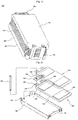
- FIG. 1 A preferred example of secondary battery module is illustrated in FIG. 1 .
- FIG. 1 is a typical perspective view illustrating a secondary battery module 100, to which a terminal-linking member according to a preferred embodiment of the present invention is applied.
- the battery module 100 includes an upper case 110, a lower case 120, a plurality of unit cells 200, a first circuit unit 130, a second circuit unit 140, and a third circuit unit 150.
- the unit cells 200 are stacked between the upper case 110 and the lower case 120, which are separated from each other.
- the first circuit unit 130 is mounted at the front surface of the battery module 100
- the second circuit unit 140 is mounted at the lower surface of the battery module 100
- the third circuit unit 150 is mounted at the rear surface of the battery module 100.
- the number of the unit cells 200, which are stackable one on another, is not limited by the upper case 110 and the lower case 120. Consequently, it is possible to easily design the battery module 100, such that the battery module 100 has desired electrical capacity and output, by modifying the first circuit unit 130 and the third circuit unit 150 depending upon the number of the stacked unit cells 200. Also, the unit cells 200 are exposed, and therefore, heat dissipation is efficiently accomplished while the unit cells 200 are charged or discharged. According to circumstances, the upper case 110 may be omitted.
- the first circuit unit 130 is mounted at one side surface of the battery module 100 adjacent to electrode terminals of the unit cells 200, and the first circuit unit 130 includes a connecting member according to the present invention for connecting the unit cells 200 in parallel or in series with each other and a sensing board assembly for sensing voltage and/or current signals of the respective unit cells 200.
- the second circuit unit 140 is electrically connected to the first circuit unit 130, and the second circuit unit 140 includes a main board assembly for controlling the battery module 100.
- the main board assembly is mounted in a lower receiving part of the lower case 120. The temperature of the battery may be sensed by the main board assembly.
- the third circuit unit 150 is electrically connected to the second circuit unit 140. Also, the third circuit unit 150 is connected to an external input/output terminal while preventing overcurrent during charging and discharging electricity.
- the third circuit unit 150 is mounted at the other side surface of the battery module 100 such that the third circuit unit 150 is opposite to the first circuit unit 130.
- the first circuit unit 130, the second circuit unit 140, and the third circuit unit 150 may be partially or wholly constructed in a combined structure. Also, these circuit units 130, 140, and 150 may be partially or wholly mounted at the same position of the battery module, i.e., one or two surfaces of the battery module. These constructions of the circuit units must be interpreted to be within the scope of the present invention.
- FIG. 2 is a perspective view illustrating stacking of the unit cells on the lower case of the battery module shown in FIG. 1 .
- the lower case 120 is a rectangular structure almost corresponding to the outer appearance of the unit cell 200.
- the lower case 120 includes an upper receiving part 121, in which the unit cell 200 is received.
- the lower case 120 may be a simple plate structure.
- the lower case 120 is made of a plastic resin, such as acrylonitrile-butadiene-styrene (ABS), polycarbonate (PC), or polybutylene terephthalate (PBT), which has high strength and electrical insulation.
- ABS acrylonitrile-butadiene-styrene
- PC polycarbonate
- PBT polybutylene terephthalate
- the unit cell 200 stacked on the lower case 120 is a pouch-shaped secondary cell, which has a cathode terminal 220 and an anode terminal 230 protruding from the upper end of a cell body 210.
- a cathode terminal 220 and an anode terminal 230 protruding from the upper end of a cell body 210.
- At the electrode terminals 220 and 230 are formed though-holes 240, respectively.
- Additional fixing members for example, fasteners 500, are inserted through the through-holes 240 and fixing holes 122 formed in the lower case 120, while the unit cells 200 and 201 are stacked, and then nuts (not shown) are fitted on the fasteners 500 at the lower surface of the lower case 120. Consequently, the unit cells 200 and 201 are fixed to each other.
- an insulating member 300 for accomplishing the electrical insulation between the unit cells 200 and 201.
- protrusions 310 which are fitted in the though-holes 240 of the electrode terminals 220 and 230.
- protrusions 310 are also formed through-holes 320, and therefore, the electrical insulation between the fasteners 500 inserted through the through holes 320 of the protrusions 310 and the electrode terminals 220 and 230 is maintained.
- double-sided adhesive tapes 600 are attached to the cell body 210 of the unit cell 200, whereby more stable coupling between the stacked unit cells 200 and 201 is guaranteed. Furthermore, the stacked unit cells 200 and 201 are spaced apart from each other by the thickness of the double-sided adhesive tapes 600. The gap between the stacked unit cells 200 and 201 serves to absorb the change in volume of the unit cells 200 and 201 while the unit cells 200 and 201 are charged or discharged and to effectively dissipate heat generated from the unit cells 200 and 201 while the unit cells 200 and 201 are charged or discharged.
- FIG. 3 is a typical view illustrating an assembly-type insulating member 300 according to a preferred embodiment of the present invention before assembly of the insulating member.
- the insulating member 300 comprises: a first assembly unit body 330 having a female coupling part 331 formed at one side thereof; and a second assembly unit body 340 having a male coupling part 341 formed at one side thereof such that the male coupling part 341 corresponds to the female coupling part 331.
- the first assembly unit body 330 and the second assembly unit body 340 are coupled with or separated from each other.
- the insulating member 300 is constructed in the shape of a rectangular block when the first assembly unit body 330 and the second assembly unit body 340 are coupled with each other.
- coupling protrusions 350 At the outside parts of the upper ends of the respective assembly unit bodies 330 and 340 are formed coupling protrusions 350, by which the assembly unit bodies 330 and 340 are coupled with another insulating member (not shown) stacked on the assembly unit bodies 330 and 340.
- coupling grooves 352 At the lower end surfaces of the assembly unit bodies 330 and 340 are formed coupling grooves 352, which correspond to the coupling protrusions 350.
- the protrusions 310 are formed at the middle parts of the upper ends of the respective assembly unit bodies 330 and 340 such that the protrusions 310 are fitted in the though-holes (not shown) of the electrode terminals of the unit cell, as shown in FIG. 2 .
- a hollow part 343 by which a connecting member (not shown) is coupled with the insulating member 300 constructed by coupling the first assembly unit body 330 and the second assembly unit body 340.
- FIG. 4 is a typical view illustrating a separation-type connecting member 400 according to a preferred embodiment of the present invention.
- the separation-type connecting member 400 comprises: a first terminal connecting body 410, which is connected to one of the electrode terminals of the unit cell (for example, the cathode terminal); and a second terminal connecting body 420, which is connected to the other electrode terminal of the unit cell (for example, the anode terminal).
- the terminal connecting bodies 410 and 420 are made of a conductive material and formed in the shape of a plate. At the respective terminal connecting bodies 410 and 420 are formed engaging holes 412 and 422, in which the protrusions 310 of the insulating member (see FIG. 3 ) are fitted.
- the engaging hole 412 formed at the first terminal connecting body 410 is constructed in a closed type such that the corresponding protrusion of the insulating member is fitted into the engaging hole 412 of the first terminal connecting body 410 only from above.
- the engaging hole 422 formed at the second terminal connecting body 420 is constructed in an open type such that the corresponding protrusion of the insulating member is fitted into the engaging hole 422 of the second terminal connecting body 410 from both above and side.
- a connecting extension part 415 which protrudes from the side thereof such that the connecting extension part 415 can be connected to the sensing board assembly in the assembled state.
- Each of the engaging parts 430 and 440 includes a first bent section 431 formed by bending inwardly a main body, which is made of a plate-shaped material, at a predetermined height and a second bent section 432 formed by vertically bending the first bent section 431. Consequently, the engaging parts 430 and 440 can be elastically engaged in the hollow part of the insulating member.
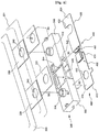
- FIG. 5 is a typical view partially illustrating the connection of electrode terminals of the unit cells using the assembly-type insulating member shown in FIG. 3 and the separation-type connecting member shown in FIG. 4 . Specifically, the connection of the unit cells 200 and 201 in series using the insulating member 300 and the connecting member 400 is illustrated in FIG. 5 .
- the engaging parts 430 and 440 of the first and second terminal connecting bodies 410 and 420 of the connecting member are securely inserted into the hollow part 343 of the second assembly unit body 340 of the insulating member.
- the engaging part 430 of the first terminal connecting body 410 is inserted into the hollow part 343 with the engaging part 430 upward, and the plate-shaped main body 414 covers the lower end surfaces of the first assembly unit body 330 and the second assembly unit body 340.
- the side bent section 431 of the engaging part 430 is moved inward along a lower guide groove 345 formed a predetermined length at the lower end of the hollow part 343.
- the engaging part 430 of the first terminal connecting body 410 When the engaging part 430 of the first terminal connecting body 410 is inserted into the hollow part 343 of the insulating member 300, the first terminal connecting body 410 is mounted at the lower end surface of another insulating member (not shown) having no projections. For this reason, the engaging hole 412 is formed in the closed type.
- the engaging part 440 of the second terminal connecting body 420 is inserted into the hollow part 343 with the engaging part 440 downward, and the plate-shaped main body 424 covers the upper end surface of the second assembly unit body 340.
- the side bent section 441 of the engaging part 440 is moved inward along an upper guide groove 344 formed a predetermined length at the upper end of the hollow part 343.
- the engaging part 440 of the second terminal connecting body 420 is inserted into the hollow part 343 of the insulating member 300, the second terminal connecting body 420 is mounted at the upper end surface of the insulating member 300 having the protrusions 312. For this reason, the engaging hole 422 is formed in the open type.
- the two terminal connecting bodies 410 and 420 remain separated from each other as shown in the drawing (showing the state before the coupling) even after the terminal connecting bodies 410 and 420 are coupled to the insulating member 300.
- the first terminal connecting body 410 is connected to a cathode terminal 221 of the unit cell 201 coupled to the lower end surface of the first assembly unit body 330, and the second terminal connecting body 420 is connected to an anode terminal 230 of the unit cell 200 coupled to the protrusion 312 of the second assembly unit body 340.
- the second terminal connecting body 420 is coupled to the second assembly unit body 340 (S1).
- the first terminal connecting body 410 is coupled to the second assembly unit body 340 (S2).
- the engaging hole 422 of the second terminal connecting body 420 coupled to the second assembly unit body 340 as described above is aligned with the through-hole 240 of the anode terminal 230 of the unit cell 200 (S3).
- the first assembly unit body 330 is coupled to the second assembly unit body 340 (S4).
- the unit cell 200 is mounted at the insulating member 300 such that the protrusion 310 is fitted in the though-hole 240 of the cathode terminal 220, and the protrusion 312 is fitted in the through-hole 240 of the anode terminal 230 (S5).
- the cathode terminal 220 is brought into contact with another first terminal connecting body (not shown) to be coupled from above while the cathode terminal 220 is coupled to the protrusion 310.
- the anode terminal 230 is brought into contact with the second terminal connecting body 420, which is coupled to the protrusion 312.
- the above-described assembly process is merely an example of a possible assembly process, and the sequence of the assembly process may be partially changed.
- the step of coupling the first assembly unit body 330 and the second assembly unit body 340 (S4) may be carried out first.
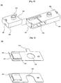
- FIG. 6 is a typical view illustrating the connection of the first terminal connecting body and the second terminal connecting body with a fuse after the assembly process shown in FIG. 5 is completed.
- FIG. 6 illustrates the electrical connection using a fuse 700, which is a kind of safety element.
- the fuse 700 includes a fuse body 710 having a region that may break when overcurrent or overheating occurs and two connecting terminals 720 and 730 extending from the fuse body 710.
- Elastic connecting grooves 433 and 443 are formed at the engaging parts 430 and 440 of the first and second terminal connecting bodies 410 and 420 while the first terminal connecting body 410 and the second terminal connecting body 420 are coupled to the insulating member 300.
- the connecting terminals 720 and 730 of the fuse 700 are inserted into the connecting grooves 433 and 443, whereby the electrical connection between the first terminal connecting body 410 and the second terminal connecting body 420 is accomplished.
- the fuse 700 is broken.
- the battery module is disassembled, the broken fuse 700 is removed, and a new fuse is coupled to first terminal connecting body 410 and the second terminal connecting body 420.
- the first terminal connecting body 410 and the second terminal connecting body 420 may be formed as a single body.
- the terminal-linking member of the secondary battery module has the effect of accomplishing easy and stable connection of the electrode terminals of the unit cells, securely stacking the unit cells without using additional mounting members, such as cartridges, reducing a possibility of short circuits during manufacturing the secondary battery module, enabling a safety element to be easily mounted during the assembly of the battery module or during the use of the completed battery module, and performing an electric potential leveling process to the unit cells.
Landscapes
- Chemical & Material Sciences (AREA)
- Chemical Kinetics & Catalysis (AREA)
- Electrochemistry (AREA)
- General Chemical & Material Sciences (AREA)
- Engineering & Computer Science (AREA)
- Manufacturing & Machinery (AREA)
- Connection Of Batteries Or Terminals (AREA)
- Battery Mounting, Suspending (AREA)
Claims (13)
- Anschlussverknüpfungsglied eines Sekundärbatteriemoduls, das Einheitszellen aufeinandergestapelt und elektrisch miteinander verbunden aufweist, wobei das Anschlussverknüpfungsglied umfasst:ein Isolierungsglied, angebracht zwischen Elektrodenanschlüssen der benachbarten Einheitszellen zum Herstellen der elektrischen Isolierung zwischen den Elektrodenanschlüssen, wobei das Isolierungsglied an die Elektrodenanschlüsse gekoppelt ist;wobei das Isolierungsglied in der Form eines rechteckigen Blocks aufgebaut ist, der mit einem Spalt zwischen den Elektrodenanschlüssen der gestapelten Einheitszellen übereinstimmt, und das Isolierungsglied zwei Montageeinheitskörper umfasst, die derart aufgebaut sind, dass die Montageeinheitskörper miteinander gekoppelt oder voneinander getrennt sein können, wobei ein Kathodenanschluss der Einheitszelle an einen der Montageeinheitskörper gekoppelt ist, während ein Anodenanschluss der Einheitszelle an den anderen Montageeinheitskörper gekoppelt ist; undein Verbindungsglied, das an das Isolierungsglied zum elektrischen Verbinden der Elektrodenanschlüsse der Einheitszellen gekoppelt ist, die an das Isolierungsglied in Reihe und/oder parallel miteinander gekoppelt sind,wobei das Verbindungsglied umfasst:einen ersten Anschlussverbindungskörper, der mit dem Elektrodenanschluss (a) der Einheitszelle (A) verbunden ist; undeinen zweiten Anschlussverbindungskörper, der mit dem Elektrodenanschluss (b) der Einheitszelle (B), benachbart der Einheitszelle (A), verbunden ist undwobei der erste Anschlussverbindungskörper und der zweite Anschlussverbindungskörper voneinander getrennt sind.
- Anschlussverknüpfungsglied nach Anspruch 1, wobei die Elektrodenanschlüsse der Einheitszellen mit Durchgangsbohrungen ausgestattet sind, und das Isolierungsglied mit koppelnden Vorsprüngen ausgestattet ist, die den Durchgangsbohrungen entsprechen, so dass die koppelnden Vorsprünge des Isolierungsglieds in die Durchgangsbohrungen der Elektrodenanschlüsse eingepasst sind.
- Anschlussverknüpfungsglied nach Anspruch 2, wobei die koppelnden Vorsprünge auch mit Durchgangsbohrungen ausgestattet sind, so dass die Elektrodenanschlüsse gestapelt sind, während das Isolierungsglied zwischen den Elektrodenanschlüssen angeordnet ist, miteinander durch Kopplungsglieder, die durch die Durchgangsbohrungen der koppelnden Vorsprünge eingeschoben sind, gekoppelt sind.
- Anschlussverknüpfungsglied nach Anspruch 1,
wobei das Verbindungsglied an das Isolierungsglied in einer derartigen Weise gekoppelt ist, dass das Verbindungsglied das Isolierungsglied umgibt, oder das Verbindungsglied in Hohlteile, die an dem Isolierungsglied ausgebildet sind, eingeschoben ist. - Anschlussverknüpfungsglied nach Anspruch 1, wobei der Elektrodenanschluss (a) der Einheitszelle (A), die mit dem Verbindungsglied verbunden ist, von dem Elektrodenanschluss (b) der Einheitszelle (B), die mit dem Verbindungsglied verbunden ist, verschieden ist.
- Anschlussverknüpfungsglied nach Anspruch 1, wobei
der erste Anschlussverbindungskörper und der zweite Anschlussverbindungskörper voneinander getrennt sind,
der erste Anschlussverbindungskörper und der zweite Anschlussverbindungskörper an das Isolierungsglied gekoppelt sind, so dass der erste und zweite Anschlussverbindungskörper mit den entsprechenden Elektrodenanschlüssen verbunden ist, und
der erste Anschlussverbindungskörper und der zweite Anschlussverbindungskörper miteinander durch ein leitfähiges Glied zum Herstellen der elektrischen Verbindung zwischen dem ersten Anschlussverbindungskörper und dem zweiten Anschlussverbindungskörper verbunden sind, nachdem der erste und zweite Anschlussverbindungskörper an das Isolierungsglied gekoppelt ist. - Anschlussverknüpfungsglied nach Anspruch 6, wobei das leitfähige Glied ein Sicherheitselement ist, ausgewählt aus der Gruppe, bestehend aus einer Sicherung, einem Bimetall, und einem Element mit positivem Temperaturkoeffizienten (PTC).
- Anschlussverknüpfungsglied nach Anspruch 1,
wobei das Isolierungsglied umfasst:einen ersten Montage-Einheits-Körper mit einem Kopplungsbuchsenteil, das auf einer Seite davon ausgebildet ist; undeinen zweiten Montage-Einheits-Körper mit einem Kopplungssteckerteil, das auf einer Seite davon ausgebildet ist, wobei das Kopplungssteckerteil dem Kopplungsbuchsenteil entspricht, undwobei die entsprechenden Montageeinheitskörper an den Mittelteilen der oberen Enden davon mit Vorsprüngen ausgestattet sind, die in die Durchgangsbohrungen der Elektrodenanschlüsse der Einheitszelle eingepasst sind, und mindestens einer der ersten und zweiten Montageeinheitskörper an der Seite davon mit einem Hohlteil, durch den das Verbindungsglied an den mindestens einen der ersten und zweiten Montage-Einheits-Körper gekoppelt ist, ausgestattet ist. - Anschlussverknüpfungsglied nach Anspruch 8, wobei
die ersten und zweiten Montageeinheitskörper an den Seitenteilen der oberen Enden davon mit koppelnden Vorsprüngen ausgestattet sind, durch die die ersten und zweiten Montageeinheitskörper mit einem anderen Isolierungsglied, das auf den ersten und zweiten Montageeinheitskörpern gestapelt ist, gekoppelt sind, und
die ersten und zweiten Montageeinheitskörper an den unteren Endflächen davon mit Kopplungsrillen ausgestattet sind, die den koppelnden Vorsprüngen entsprechen. - Anschlussverknüpfungsglied nach Anspruch 1, wobei die ersten und zweiten Anschlussverbindungskörper Eingriffslöcher aufweisen, in denen die Vorsprünge des Isolierungsglieds eingepasst sind, und Eingriffsteile, die in das Hohlteil des Isolierungsglieds fest eingeschoben sind.
- Anschlussverknüpfungsglied nach Anspruch 10, wobei eines der Eingriffslöcher in einer geschlossenen Art aufgebaut ist, und das andere Eingriffsloch in einer offenen Art aufgebaut ist.
- Anschlussverknüpfungsglied nach Anspruch 10, wobei jedes der Eingriffsteile einschließt:einen ersten Abwinklungsabschnitt, der gebildet ist durch Abwinkeln eines Hauptkörpers nach innen, der aus einem platten-förmigen Material bei einer vorbestimmten Höhe hergestellt ist; undeinen zweiten Abwinklungsabschnitt, der gebildet ist durch vertikales Abwinkeln des ersten Abwinklungsabschnitts.
- Sekundärbatteriemodul, das ein Anschlussverknüpfungsglied nach einem der Ansprüche 1 bis 12 enthält.
Applications Claiming Priority (2)
| Application Number | Priority Date | Filing Date | Title |
|---|---|---|---|
| KR20040112590 | 2004-12-24 | ||
| PCT/KR2005/004029 WO2006068372A1 (en) | 2004-12-24 | 2005-11-29 | Terminal-linking member of secondary battery module |
Publications (3)
| Publication Number | Publication Date |
|---|---|
| EP1829163A1 EP1829163A1 (de) | 2007-09-05 |
| EP1829163A4 EP1829163A4 (de) | 2012-06-20 |
| EP1829163B1 true EP1829163B1 (de) | 2017-06-07 |
Family
ID=36601933
Family Applications (1)
| Application Number | Title | Priority Date | Filing Date |
|---|---|---|---|
| EP05821409.9A Active EP1829163B1 (de) | 2004-12-24 | 2005-11-29 | Anschlussverknüpfungsglied eines sekundärbatteriemoduls |
Country Status (10)
| Country | Link |
|---|---|
| US (1) | US7638237B2 (de) |
| EP (1) | EP1829163B1 (de) |
| JP (1) | JP5138379B2 (de) |
| KR (1) | KR100905391B1 (de) |
| CN (1) | CN100553045C (de) |
| BR (1) | BRPI0518590B8 (de) |
| CA (1) | CA2589890C (de) |
| RU (1) | RU2337432C1 (de) |
| TW (1) | TWI302766B (de) |
| WO (1) | WO2006068372A1 (de) |
Families Citing this family (56)
| Publication number | Priority date | Publication date | Assignee | Title |
|---|---|---|---|---|
| EP2590242B1 (de) * | 2004-12-24 | 2019-09-18 | LG Chem, Ltd. | Verfahren und Vorrichtung zur Verbesserung der Leistung eines Batteriemoduls durch Angleichen der Spannung |
| CN2819483Y (zh) * | 2005-04-15 | 2006-09-20 | 金达时发展有限公司 | 薄板型锂电池的可组合连接架 |
| KR100948970B1 (ko) * | 2006-03-13 | 2010-03-23 | 주식회사 엘지화학 | 완충부재가 설치되어 있는 중대형 전지모듈 |
| JP5024811B2 (ja) * | 2006-03-17 | 2012-09-12 | 国立大学法人静岡大学 | 電動車両の電源装置 |
| JP4674722B2 (ja) * | 2006-03-17 | 2011-04-20 | 国立大学法人静岡大学 | 電動車両の電源供給装置 |
| KR100886571B1 (ko) * | 2006-08-07 | 2009-03-05 | 주식회사 엘지화학 | 전지팩 케이스 |
| KR101026746B1 (ko) * | 2006-08-28 | 2011-04-08 | 주식회사 엘지화학 | 전기 단자 연결용 접속장치 |
| KR100863726B1 (ko) * | 2006-09-18 | 2008-10-16 | 주식회사 엘지화학 | 균일 분배형 버스 바 및 이를 포함하는 중대형 전지팩 |
| KR100934466B1 (ko) * | 2006-09-25 | 2009-12-30 | 주식회사 엘지화학 | 전지셀들의 전기적 연결을 위한 접속부재 |
| US7858229B2 (en) * | 2006-09-25 | 2010-12-28 | Lg Chem, Ltd. | Cell-module cartridge, cell-module including the cell-module cartridge, and battery module including the cell-module |
| KR100908568B1 (ko) * | 2006-10-23 | 2009-07-22 | 주식회사 엘지화학 | 균일 분배형 접속부재 및 이를 포함하는 중대형 전지팩 |
| KR100889241B1 (ko) | 2006-10-23 | 2009-03-17 | 주식회사 엘지화학 | 전지모듈의 전극단자 접속부재 |
| KR101108445B1 (ko) * | 2007-07-04 | 2012-01-31 | 주식회사 엘지화학 | 이차전지의 기계적 접속방법 및 이를 위한 접속부재 |
| KR100998301B1 (ko) | 2007-11-08 | 2010-12-03 | 삼성에스디아이 주식회사 | 배터리 팩 및 이를 구비하는 전자기기 |
| US8035986B2 (en) * | 2008-06-30 | 2011-10-11 | Lg Chem, Ltd. | Battery cell interconnect and voltage sensing assembly and method for coupling battery cell assemblies thereto |
| US8163412B2 (en) * | 2008-06-30 | 2012-04-24 | Lg Chem, Ltd. | Battery cell interconnect and voltage sensing assembly and method for coupling a battery cell assembly thereto |
| US7563137B1 (en) * | 2008-06-30 | 2009-07-21 | Lg Chem, Ltd. | Mechanical fastener for coupling to electrical terminals of battery modules and method for coupling to electrical terminals |
| DE102008039412A1 (de) * | 2008-08-12 | 2010-02-18 | Würth Elektronik Ics Gmbh & Co. Kg | Verbindungsanordnung |
| US9028986B2 (en) * | 2009-01-07 | 2015-05-12 | A123 Systems Llc | Fuse for battery cells |
| US8815429B2 (en) * | 2009-01-12 | 2014-08-26 | A123 Systems Llc | Busbar supports and methods of their use for battery systems |
| KR101104650B1 (ko) * | 2009-03-24 | 2012-01-13 | 에스케이이노베이션 주식회사 | 외장 부재가 구비된 차량용 배터리팩 |
| US8098126B2 (en) * | 2009-04-22 | 2012-01-17 | Lg Chem, Ltd. | High voltage service disconnect assembly |
| CN102414870B (zh) * | 2009-10-06 | 2014-07-02 | 矢崎总业株式会社 | 电池连接体 |
| CN202978302U (zh) | 2009-12-04 | 2013-06-05 | A123系统公司 | 具有集成的电源管理系统和可伸缩电池断路组件的电池系统 |
| DE102010005017A1 (de) * | 2010-01-19 | 2011-07-21 | Li-Tec Battery GmbH, 01917 | Elektroenergieeinheit und Distanzstück |
| KR101053208B1 (ko) * | 2010-02-09 | 2011-08-01 | 주식회사 엘지화학 | 용접 신뢰성이 향상된 전지모듈 및 이를 포함하는 중대형 전지팩 |
| JP5715766B2 (ja) | 2010-04-22 | 2015-05-13 | 矢崎総業株式会社 | 配線材の接続構造 |
| US8480426B2 (en) * | 2010-06-09 | 2013-07-09 | Delta Electronics, Inc. | Battery connecting tabs |
| KR101212614B1 (ko) | 2010-07-08 | 2012-12-14 | 주식회사 엘지화학 | 신규한 구조의 접속단자 및 이를 위한 제조방법 |
| JP2012089323A (ja) * | 2010-10-19 | 2012-05-10 | Nifco Inc | 電池モジュール用電極構成体 |
| KR101281744B1 (ko) * | 2010-11-18 | 2013-07-04 | 주식회사 엘지화학 | 안전성의 향상을 위한 부재를 전지셀들 사이에 포함하고 있는 전지모듈 |
| FR2967823B1 (fr) * | 2010-11-19 | 2015-05-22 | Renault Sa | Batterie d'accumulateurs et procede de detection d'un echauffement correspondant |
| US9178192B2 (en) | 2011-05-13 | 2015-11-03 | Lg Chem, Ltd. | Battery module and method for manufacturing the battery module |
| KR101275811B1 (ko) * | 2011-05-19 | 2013-06-18 | 삼성에스디아이 주식회사 | 전지 팩 |
| US9496544B2 (en) | 2011-07-28 | 2016-11-15 | Lg Chem. Ltd. | Battery modules having interconnect members with vibration dampening portions |
| KR101282519B1 (ko) | 2011-08-02 | 2013-07-04 | 로베르트 보쉬 게엠베하 | 배터리 모듈 |
| US8974938B2 (en) | 2011-08-30 | 2015-03-10 | Lg Chem, Ltd. | Battery system and method for coupling a battery cell assembly to an electrically non-conductive base member |
| US8871376B2 (en) | 2011-08-31 | 2014-10-28 | Lg Chem, Ltd. | Interconnection assemblies and methods for forming the interconnection assemblies in a battery module |
| US8846240B2 (en) | 2012-02-16 | 2014-09-30 | Lg Chem, Ltd. | Battery cell interconnect and voltage sensing assembly and method of manufacturing the assembly |
| KR101401477B1 (ko) * | 2012-08-02 | 2014-05-29 | 주식회사 엘지화학 | 이차전지용 커넥팅 부품, 이를 포함하는 배터리 모듈 및 배터리 팩 |
| KR101397025B1 (ko) | 2012-09-10 | 2014-05-21 | 삼성에스디아이 주식회사 | 리드탭 조립체 및 이를 구비한 전지 모듈 |
| WO2014091635A1 (ja) * | 2012-12-16 | 2014-06-19 | エクセルギー・パワー・システムズ株式会社 | 積層電池および積層電池の組立方法 |
| JP2014180145A (ja) * | 2013-03-15 | 2014-09-25 | Yazaki Corp | ヒューズブロック |
| US9281673B2 (en) * | 2014-04-03 | 2016-03-08 | Ford Global Technologies, Llc | Deformable busbar assembly and bus bar installation method |
| US9437859B2 (en) | 2014-04-07 | 2016-09-06 | Lg Chem, Ltd. | Battery cell interconnect and voltage sensing assembly and a battery module |
| US9620761B2 (en) | 2014-09-09 | 2017-04-11 | Lg Chem, Ltd. | Battery cell interconnect and voltage sensing assembly and a battery module |
| US10020483B2 (en) | 2015-02-09 | 2018-07-10 | Lg Chem, Ltd. | Battery module and method of coupling first and second electrical terminals of first and second battery cells to a voltage sense member of an interconnect assembly |
| US9905892B2 (en) | 2015-02-09 | 2018-02-27 | Lg Chem, Ltd. | Battery module and method of coupling first and second electrical terminals of first and second battery cells to first and second voltage sense members of an interconnect assembly |
| KR102063935B1 (ko) * | 2015-10-13 | 2020-01-08 | 주식회사 엘지화학 | 배터리 모듈 |
| KR102651576B1 (ko) * | 2016-10-18 | 2024-03-27 | 삼성전자주식회사 | 배터리 모듈을 포함하는 전자 장치 및 제조 방법 |
| KR20200021450A (ko) | 2017-06-27 | 2020-02-28 | 세키스이가가쿠 고교가부시키가이샤 | 전지 모듈 및 전지 모듈의 제조 방법 |
| KR102328124B1 (ko) * | 2018-01-26 | 2021-11-17 | 주식회사 엘지에너지솔루션 | 전지 모듈 및 전지 모듈 어셈블리 |
| CN108649175B (zh) * | 2018-06-20 | 2023-11-24 | 宁德时代新能源科技股份有限公司 | 输出极片及电池模组 |
| CN113451633B (zh) * | 2020-03-27 | 2024-07-16 | 三星Sdi株式会社 | 电池单元的堆叠及其组装方法、电池模块和车辆 |
| KR20240048328A (ko) | 2022-10-06 | 2024-04-15 | 현대자동차주식회사 | 센싱 블록 및 이를 포함하는 배터리 모듈 조립체 |
| KR20240048322A (ko) | 2022-10-06 | 2024-04-15 | 현대자동차주식회사 | 배터리 셀 카트리지, 이를 포함하는 배터리 모듈 조립체, 및 이를 포함하는 배터리 팩 조립체 |
Citations (1)
| Publication number | Priority date | Publication date | Assignee | Title |
|---|---|---|---|---|
| WO2004082044A1 (en) * | 2003-03-13 | 2004-09-23 | Lg Chem Ltd. | Secondary lithium battery module |
Family Cites Families (14)
| Publication number | Priority date | Publication date | Assignee | Title |
|---|---|---|---|---|
| US4047239A (en) * | 1974-11-07 | 1977-09-06 | Allis-Chalmers Corporation | Stationary induction apparatus having means to monitor insulation dryness |
| AU2611088A (en) * | 1987-10-23 | 1989-05-23 | James M. Shannon | Intercell connection and method and apparatus for making connector |
| US5470255A (en) * | 1993-03-23 | 1995-11-28 | The Whitaker Corporation | Extended height connector for a battery |
| US5795181A (en) * | 1995-01-24 | 1998-08-18 | The Whitaker Corporation | Connector on a battery |
| JP3344231B2 (ja) * | 1996-08-21 | 2002-11-11 | 松下電器産業株式会社 | 電池の接続構造 |
| FR2759523B1 (fr) * | 1997-02-10 | 1999-03-19 | Alsthom Cge Alcatel | Bloc d'alimentation d'un dispositif portatif, du type permettant l'utilisation de differents types d'alimentation, et dispositif portatif correspondant |
| JP2001263314A (ja) * | 2000-03-17 | 2001-09-26 | Honda Motor Co Ltd | マグネシウム合金部材のボルト締結構造 |
| JP2001307610A (ja) * | 2000-04-17 | 2001-11-02 | Sanyo Electric Co Ltd | ヒューズの製造方法とこのヒューズを内蔵するパック電池 |
| JP3988570B2 (ja) * | 2002-08-01 | 2007-10-10 | トヨタ自動車株式会社 | 積層型電池 |
| JP2004327311A (ja) * | 2003-04-25 | 2004-11-18 | Toyota Motor Corp | 電池の接続構造及び接続方法 |
| US6773301B1 (en) * | 2003-05-08 | 2004-08-10 | Jeffrey R. Chaskin | Cell strap for combining cells into a battery |
| US7291422B2 (en) * | 2003-10-10 | 2007-11-06 | Nissan Motor Co., Ltd. | Battery and related method |
| KR100556101B1 (ko) * | 2003-12-16 | 2006-03-03 | 주식회사 엘지화학 | 이차전지 모듈 |
| EP2590242B1 (de) * | 2004-12-24 | 2019-09-18 | LG Chem, Ltd. | Verfahren und Vorrichtung zur Verbesserung der Leistung eines Batteriemoduls durch Angleichen der Spannung |
-
2005
- 2005-09-20 KR KR1020050087175A patent/KR100905391B1/ko active IP Right Grant
- 2005-11-29 BR BRPI0518590A patent/BRPI0518590B8/pt active IP Right Grant
- 2005-11-29 EP EP05821409.9A patent/EP1829163B1/de active Active
- 2005-11-29 RU RU2007120578/09A patent/RU2337432C1/ru active
- 2005-11-29 CA CA2589890A patent/CA2589890C/en active Active
- 2005-11-29 WO PCT/KR2005/004029 patent/WO2006068372A1/en active Application Filing
- 2005-11-29 CN CNB2005800414260A patent/CN100553045C/zh active Active
- 2005-11-29 JP JP2007541110A patent/JP5138379B2/ja active Active
- 2005-12-09 TW TW094143628A patent/TWI302766B/zh active
- 2005-12-23 US US11/317,872 patent/US7638237B2/en active Active
Patent Citations (1)
| Publication number | Priority date | Publication date | Assignee | Title |
|---|---|---|---|---|
| WO2004082044A1 (en) * | 2003-03-13 | 2004-09-23 | Lg Chem Ltd. | Secondary lithium battery module |
Also Published As
| Publication number | Publication date |
|---|---|
| JP5138379B2 (ja) | 2013-02-06 |
| US20060194101A1 (en) | 2006-08-31 |
| KR100905391B1 (ko) | 2009-06-30 |
| KR20060073432A (ko) | 2006-06-28 |
| TWI302766B (en) | 2008-11-01 |
| JP2008520076A (ja) | 2008-06-12 |
| US7638237B2 (en) | 2009-12-29 |
| BRPI0518590B1 (pt) | 2018-02-14 |
| CA2589890A1 (en) | 2006-06-29 |
| CN101069328A (zh) | 2007-11-07 |
| EP1829163A4 (de) | 2012-06-20 |
| RU2337432C1 (ru) | 2008-10-27 |
| BRPI0518590A2 (pt) | 2008-11-25 |
| CN100553045C (zh) | 2009-10-21 |
| BRPI0518590B8 (pt) | 2023-01-17 |
| WO2006068372A1 (en) | 2006-06-29 |
| CA2589890C (en) | 2012-01-31 |
| EP1829163A1 (de) | 2007-09-05 |
| TW200638624A (en) | 2006-11-01 |
Similar Documents
| Publication | Publication Date | Title |
|---|---|---|
| EP1829163B1 (de) | Anschlussverknüpfungsglied eines sekundärbatteriemoduls | |
| CA2592245C (en) | Separable connecting member for secondary battery module and method of improving the performance of battery module by leveling voltage | |
| EP1839349B1 (de) | Messleiterplattenbaugruppe für ein sekundärbatteriemodul | |
| KR100876456B1 (ko) | 분리형 커넥팅 부재 및 그것을 이용한 이차전지 모듈의제조방법 | |
| EP1991880B1 (de) | Spannungsmessglied und batteriemodul damit | |
| US7892669B2 (en) | Middle or large-sized battery module | |
| KR100863729B1 (ko) | 전지모듈 인터페이스 | |
| EP2450981B1 (de) | Sekundärbatteriemodul | |
| JP2008520076A5 (de) |
Legal Events
| Date | Code | Title | Description |
|---|---|---|---|
| PUAI | Public reference made under article 153(3) epc to a published international application that has entered the european phase |
Free format text: ORIGINAL CODE: 0009012 |
|
| 17P | Request for examination filed |
Effective date: 20070531 |
|
| AK | Designated contracting states |
Kind code of ref document: A1 Designated state(s): AT BE BG CH CY CZ DE DK EE ES FI FR GB GR HU IE IS IT LI LT LU LV MC NL PL PT RO SE SI SK TR |
|
| AX | Request for extension of the european patent |
Extension state: AL BA HR MK YU |
|
| A4 | Supplementary search report drawn up and despatched |
Effective date: 20120522 |
|
| RIC1 | Information provided on ipc code assigned before grant |
Ipc: H01R 13/46 20060101AFI20120515BHEP |
|
| 17Q | First examination report despatched |
Effective date: 20161018 |
|
| STAA | Information on the status of an ep patent application or granted ep patent |
Free format text: STATUS: EXAMINATION IS IN PROGRESS |
|
| GRAJ | Information related to disapproval of communication of intention to grant by the applicant or resumption of examination proceedings by the epo deleted |
Free format text: ORIGINAL CODE: EPIDOSDIGR1 |
|
| GRAP | Despatch of communication of intention to grant a patent |
Free format text: ORIGINAL CODE: EPIDOSNIGR1 |
|
| GRAP | Despatch of communication of intention to grant a patent |
Free format text: ORIGINAL CODE: EPIDOSNIGR1 |
|
| STAA | Information on the status of an ep patent application or granted ep patent |
Free format text: STATUS: GRANT OF PATENT IS INTENDED |
|
| INTG | Intention to grant announced |
Effective date: 20170331 |
|
| RIN1 | Information on inventor provided before grant (corrected) |
Inventor name: HA, JIN WOONG D-403, DONGYANG GREENAUSEU Inventor name: KIM, JEEHO 702-1802, YEOLMAEMAEUL 7-DANJI Inventor name: LEE, HANHO 103-204, HYUNDAI APT. |
|
| GRAS | Grant fee paid |
Free format text: ORIGINAL CODE: EPIDOSNIGR3 |
|
| GRAA | (expected) grant |
Free format text: ORIGINAL CODE: 0009210 |
|
| STAA | Information on the status of an ep patent application or granted ep patent |
Free format text: STATUS: THE PATENT HAS BEEN GRANTED |
|
| AK | Designated contracting states |
Kind code of ref document: B1 Designated state(s): AT BE BG CH CY CZ DE DK EE ES FI FR GB GR HU IE IS IT LI LT LU LV MC NL PL PT RO SE SI SK TR |
|
| AX | Request for extension of the european patent |
Extension state: AL BA HR MK YU |
|
| REG | Reference to a national code |
Ref country code: GB Ref legal event code: FG4D |
|
| GRAA | (expected) grant |
Free format text: ORIGINAL CODE: 0009210 |
|
| REG | Reference to a national code |
Ref country code: CH Ref legal event code: EP Ref country code: AT Ref legal event code: REF Ref document number: 899859 Country of ref document: AT Kind code of ref document: T Effective date: 20170615 |
|
| REG | Reference to a national code |
Ref country code: IE Ref legal event code: FG4D |
|
| REG | Reference to a national code |
Ref country code: DE Ref legal event code: R096 Ref document number: 602005052100 Country of ref document: DE |
|
| REG | Reference to a national code |
Ref country code: NL Ref legal event code: MP Effective date: 20170607 |
|
| REG | Reference to a national code |
Ref country code: FR Ref legal event code: PLFP Year of fee payment: 13 |
|
| REG | Reference to a national code |
Ref country code: LT Ref legal event code: MG4D |
|
| PG25 | Lapsed in a contracting state [announced via postgrant information from national office to epo] |
Ref country code: FI Free format text: LAPSE BECAUSE OF FAILURE TO SUBMIT A TRANSLATION OF THE DESCRIPTION OR TO PAY THE FEE WITHIN THE PRESCRIBED TIME-LIMIT Effective date: 20170607 Ref country code: ES Free format text: LAPSE BECAUSE OF FAILURE TO SUBMIT A TRANSLATION OF THE DESCRIPTION OR TO PAY THE FEE WITHIN THE PRESCRIBED TIME-LIMIT Effective date: 20170607 Ref country code: GR Free format text: LAPSE BECAUSE OF FAILURE TO SUBMIT A TRANSLATION OF THE DESCRIPTION OR TO PAY THE FEE WITHIN THE PRESCRIBED TIME-LIMIT Effective date: 20170908 Ref country code: LT Free format text: LAPSE BECAUSE OF FAILURE TO SUBMIT A TRANSLATION OF THE DESCRIPTION OR TO PAY THE FEE WITHIN THE PRESCRIBED TIME-LIMIT Effective date: 20170607 |
|
| REG | Reference to a national code |
Ref country code: AT Ref legal event code: MK05 Ref document number: 899859 Country of ref document: AT Kind code of ref document: T Effective date: 20170607 |
|
| PG25 | Lapsed in a contracting state [announced via postgrant information from national office to epo] |
Ref country code: NL Free format text: LAPSE BECAUSE OF FAILURE TO SUBMIT A TRANSLATION OF THE DESCRIPTION OR TO PAY THE FEE WITHIN THE PRESCRIBED TIME-LIMIT Effective date: 20170607 Ref country code: SE Free format text: LAPSE BECAUSE OF FAILURE TO SUBMIT A TRANSLATION OF THE DESCRIPTION OR TO PAY THE FEE WITHIN THE PRESCRIBED TIME-LIMIT Effective date: 20170607 Ref country code: LV Free format text: LAPSE BECAUSE OF FAILURE TO SUBMIT A TRANSLATION OF THE DESCRIPTION OR TO PAY THE FEE WITHIN THE PRESCRIBED TIME-LIMIT Effective date: 20170607 Ref country code: BG Free format text: LAPSE BECAUSE OF FAILURE TO SUBMIT A TRANSLATION OF THE DESCRIPTION OR TO PAY THE FEE WITHIN THE PRESCRIBED TIME-LIMIT Effective date: 20170907 |
|
| PG25 | Lapsed in a contracting state [announced via postgrant information from national office to epo] |
Ref country code: EE Free format text: LAPSE BECAUSE OF FAILURE TO SUBMIT A TRANSLATION OF THE DESCRIPTION OR TO PAY THE FEE WITHIN THE PRESCRIBED TIME-LIMIT Effective date: 20170607 Ref country code: RO Free format text: LAPSE BECAUSE OF FAILURE TO SUBMIT A TRANSLATION OF THE DESCRIPTION OR TO PAY THE FEE WITHIN THE PRESCRIBED TIME-LIMIT Effective date: 20170607 Ref country code: AT Free format text: LAPSE BECAUSE OF FAILURE TO SUBMIT A TRANSLATION OF THE DESCRIPTION OR TO PAY THE FEE WITHIN THE PRESCRIBED TIME-LIMIT Effective date: 20170607 Ref country code: SK Free format text: LAPSE BECAUSE OF FAILURE TO SUBMIT A TRANSLATION OF THE DESCRIPTION OR TO PAY THE FEE WITHIN THE PRESCRIBED TIME-LIMIT Effective date: 20170607 Ref country code: CZ Free format text: LAPSE BECAUSE OF FAILURE TO SUBMIT A TRANSLATION OF THE DESCRIPTION OR TO PAY THE FEE WITHIN THE PRESCRIBED TIME-LIMIT Effective date: 20170607 |
|
| PG25 | Lapsed in a contracting state [announced via postgrant information from national office to epo] |
Ref country code: IS Free format text: LAPSE BECAUSE OF FAILURE TO SUBMIT A TRANSLATION OF THE DESCRIPTION OR TO PAY THE FEE WITHIN THE PRESCRIBED TIME-LIMIT Effective date: 20171007 Ref country code: PL Free format text: LAPSE BECAUSE OF FAILURE TO SUBMIT A TRANSLATION OF THE DESCRIPTION OR TO PAY THE FEE WITHIN THE PRESCRIBED TIME-LIMIT Effective date: 20170607 Ref country code: IT Free format text: LAPSE BECAUSE OF FAILURE TO SUBMIT A TRANSLATION OF THE DESCRIPTION OR TO PAY THE FEE WITHIN THE PRESCRIBED TIME-LIMIT Effective date: 20170607 |
|
| REG | Reference to a national code |
Ref country code: DE Ref legal event code: R097 Ref document number: 602005052100 Country of ref document: DE |
|
| PLBE | No opposition filed within time limit |
Free format text: ORIGINAL CODE: 0009261 |
|
| STAA | Information on the status of an ep patent application or granted ep patent |
Free format text: STATUS: NO OPPOSITION FILED WITHIN TIME LIMIT |
|
| PG25 | Lapsed in a contracting state [announced via postgrant information from national office to epo] |
Ref country code: DK Free format text: LAPSE BECAUSE OF FAILURE TO SUBMIT A TRANSLATION OF THE DESCRIPTION OR TO PAY THE FEE WITHIN THE PRESCRIBED TIME-LIMIT Effective date: 20170607 |
|
| 26N | No opposition filed |
Effective date: 20180308 |
|
| PG25 | Lapsed in a contracting state [announced via postgrant information from national office to epo] |
Ref country code: SI Free format text: LAPSE BECAUSE OF FAILURE TO SUBMIT A TRANSLATION OF THE DESCRIPTION OR TO PAY THE FEE WITHIN THE PRESCRIBED TIME-LIMIT Effective date: 20170607 |
|
| PG25 | Lapsed in a contracting state [announced via postgrant information from national office to epo] |
Ref country code: MC Free format text: LAPSE BECAUSE OF FAILURE TO SUBMIT A TRANSLATION OF THE DESCRIPTION OR TO PAY THE FEE WITHIN THE PRESCRIBED TIME-LIMIT Effective date: 20170607 |
|
| PG25 | Lapsed in a contracting state [announced via postgrant information from national office to epo] |
Ref country code: LI Free format text: LAPSE BECAUSE OF NON-PAYMENT OF DUE FEES Effective date: 20171130 Ref country code: CH Free format text: LAPSE BECAUSE OF NON-PAYMENT OF DUE FEES Effective date: 20171130 |
|
| PG25 | Lapsed in a contracting state [announced via postgrant information from national office to epo] |
Ref country code: LU Free format text: LAPSE BECAUSE OF NON-PAYMENT OF DUE FEES Effective date: 20171129 |
|
| REG | Reference to a national code |
Ref country code: BE Ref legal event code: MM Effective date: 20171130 |
|
| REG | Reference to a national code |
Ref country code: IE Ref legal event code: MM4A |
|
| REG | Reference to a national code |
Ref country code: FR Ref legal event code: PLFP Year of fee payment: 14 |
|
| PG25 | Lapsed in a contracting state [announced via postgrant information from national office to epo] |
Ref country code: IE Free format text: LAPSE BECAUSE OF NON-PAYMENT OF DUE FEES Effective date: 20171129 |
|
| PG25 | Lapsed in a contracting state [announced via postgrant information from national office to epo] |
Ref country code: BE Free format text: LAPSE BECAUSE OF NON-PAYMENT OF DUE FEES Effective date: 20171130 |
|
| PG25 | Lapsed in a contracting state [announced via postgrant information from national office to epo] |
Ref country code: HU Free format text: LAPSE BECAUSE OF FAILURE TO SUBMIT A TRANSLATION OF THE DESCRIPTION OR TO PAY THE FEE WITHIN THE PRESCRIBED TIME-LIMIT; INVALID AB INITIO Effective date: 20051129 |
|
| PG25 | Lapsed in a contracting state [announced via postgrant information from national office to epo] |
Ref country code: CY Free format text: LAPSE BECAUSE OF NON-PAYMENT OF DUE FEES Effective date: 20170607 |
|
| PG25 | Lapsed in a contracting state [announced via postgrant information from national office to epo] |
Ref country code: TR Free format text: LAPSE BECAUSE OF FAILURE TO SUBMIT A TRANSLATION OF THE DESCRIPTION OR TO PAY THE FEE WITHIN THE PRESCRIBED TIME-LIMIT Effective date: 20170607 |
|
| PG25 | Lapsed in a contracting state [announced via postgrant information from national office to epo] |
Ref country code: PT Free format text: LAPSE BECAUSE OF FAILURE TO SUBMIT A TRANSLATION OF THE DESCRIPTION OR TO PAY THE FEE WITHIN THE PRESCRIBED TIME-LIMIT Effective date: 20170607 |
|
| REG | Reference to a national code |
Ref country code: DE Ref legal event code: R081 Ref document number: 602005052100 Country of ref document: DE Owner name: LG ENERGY SOLUTION LTD., KR Free format text: FORMER OWNER: LG CHEM, LTD., SEOUL, KR Ref country code: DE Ref legal event code: R081 Ref document number: 602005052100 Country of ref document: DE Owner name: LG ENERGY SOLUTION, LTD., KR Free format text: FORMER OWNER: LG CHEM, LTD., SEOUL, KR |
|
| P01 | Opt-out of the competence of the unified patent court (upc) registered |
Effective date: 20230408 |
|
| REG | Reference to a national code |
Ref country code: GB Ref legal event code: 732E Free format text: REGISTERED BETWEEN 20230824 AND 20230831 |
|
| REG | Reference to a national code |
Ref country code: DE Ref legal event code: R081 Ref document number: 602005052100 Country of ref document: DE Owner name: LG ENERGY SOLUTION, LTD., KR Free format text: FORMER OWNER: LG ENERGY SOLUTION LTD., SEOUL, KR |
|
| PGFP | Annual fee paid to national office [announced via postgrant information from national office to epo] |
Ref country code: GB Payment date: 20231023 Year of fee payment: 19 |
|
| PGFP | Annual fee paid to national office [announced via postgrant information from national office to epo] |
Ref country code: FR Payment date: 20231024 Year of fee payment: 19 Ref country code: DE Payment date: 20231023 Year of fee payment: 19 |