EP1817154B1 - Schweissstruktur für ein saugrohr aus synthetischem harz - Google Patents
Schweissstruktur für ein saugrohr aus synthetischem harz Download PDFInfo
- Publication number
- EP1817154B1 EP1817154B1 EP05818845A EP05818845A EP1817154B1 EP 1817154 B1 EP1817154 B1 EP 1817154B1 EP 05818845 A EP05818845 A EP 05818845A EP 05818845 A EP05818845 A EP 05818845A EP 1817154 B1 EP1817154 B1 EP 1817154B1
- Authority
- EP
- European Patent Office
- Prior art keywords
- welding
- synthetic resin
- protrusion
- joining
- intake manifold
- Prior art date
- Legal status (The legal status is an assumption and is not a legal conclusion. Google has not performed a legal analysis and makes no representation as to the accuracy of the status listed.)
- Expired - Lifetime
Links
Images
Classifications
-
- F—MECHANICAL ENGINEERING; LIGHTING; HEATING; WEAPONS; BLASTING
- F02—COMBUSTION ENGINES; HOT-GAS OR COMBUSTION-PRODUCT ENGINE PLANTS
- F02M—SUPPLYING COMBUSTION ENGINES IN GENERAL WITH COMBUSTIBLE MIXTURES OR CONSTITUENTS THEREOF
- F02M35/00—Combustion-air cleaners, air intakes, intake silencers, or induction systems specially adapted for, or arranged on, internal-combustion engines
- F02M35/10—Air intakes; Induction systems
- F02M35/1034—Manufacturing and assembling intake systems
- F02M35/10354—Joining multiple sections together
- F02M35/1036—Joining multiple sections together by welding, bonding or the like
-
- B—PERFORMING OPERATIONS; TRANSPORTING
- B29—WORKING OF PLASTICS; WORKING OF SUBSTANCES IN A PLASTIC STATE IN GENERAL
- B29C—SHAPING OR JOINING OF PLASTICS; SHAPING OF MATERIAL IN A PLASTIC STATE, NOT OTHERWISE PROVIDED FOR; AFTER-TREATMENT OF THE SHAPED PRODUCTS, e.g. REPAIRING
- B29C65/00—Joining or sealing of preformed parts, e.g. welding of plastics materials; Apparatus therefor
- B29C65/02—Joining or sealing of preformed parts, e.g. welding of plastics materials; Apparatus therefor by heating, with or without pressure
- B29C65/06—Joining or sealing of preformed parts, e.g. welding of plastics materials; Apparatus therefor by heating, with or without pressure using friction, e.g. spin welding
-
- B—PERFORMING OPERATIONS; TRANSPORTING
- B29—WORKING OF PLASTICS; WORKING OF SUBSTANCES IN A PLASTIC STATE IN GENERAL
- B29C—SHAPING OR JOINING OF PLASTICS; SHAPING OF MATERIAL IN A PLASTIC STATE, NOT OTHERWISE PROVIDED FOR; AFTER-TREATMENT OF THE SHAPED PRODUCTS, e.g. REPAIRING
- B29C66/00—General aspects of processes or apparatus for joining preformed parts
- B29C66/01—General aspects dealing with the joint area or with the area to be joined
- B29C66/05—Particular design of joint configurations
- B29C66/10—Particular design of joint configurations particular design of the joint cross-sections
- B29C66/11—Joint cross-sections comprising a single joint-segment, i.e. one of the parts to be joined comprising a single joint-segment in the joint cross-section
- B29C66/114—Single butt joints
- B29C66/1142—Single butt to butt joints
-
- B—PERFORMING OPERATIONS; TRANSPORTING
- B29—WORKING OF PLASTICS; WORKING OF SUBSTANCES IN A PLASTIC STATE IN GENERAL
- B29C—SHAPING OR JOINING OF PLASTICS; SHAPING OF MATERIAL IN A PLASTIC STATE, NOT OTHERWISE PROVIDED FOR; AFTER-TREATMENT OF THE SHAPED PRODUCTS, e.g. REPAIRING
- B29C66/00—General aspects of processes or apparatus for joining preformed parts
- B29C66/01—General aspects dealing with the joint area or with the area to be joined
- B29C66/05—Particular design of joint configurations
- B29C66/10—Particular design of joint configurations particular design of the joint cross-sections
- B29C66/13—Single flanged joints; Fin-type joints; Single hem joints; Edge joints; Interpenetrating fingered joints; Other specific particular designs of joint cross-sections not provided for in groups B29C66/11 - B29C66/12
- B29C66/131—Single flanged joints, i.e. one of the parts to be joined being rigid and flanged in the joint area
- B29C66/1312—Single flange to flange joints, the parts to be joined being rigid
-
- B—PERFORMING OPERATIONS; TRANSPORTING
- B29—WORKING OF PLASTICS; WORKING OF SUBSTANCES IN A PLASTIC STATE IN GENERAL
- B29C—SHAPING OR JOINING OF PLASTICS; SHAPING OF MATERIAL IN A PLASTIC STATE, NOT OTHERWISE PROVIDED FOR; AFTER-TREATMENT OF THE SHAPED PRODUCTS, e.g. REPAIRING
- B29C66/00—General aspects of processes or apparatus for joining preformed parts
- B29C66/01—General aspects dealing with the joint area or with the area to be joined
- B29C66/05—Particular design of joint configurations
- B29C66/301—Three-dimensional joints, i.e. the joined area being substantially non-flat
-
- B—PERFORMING OPERATIONS; TRANSPORTING
- B29—WORKING OF PLASTICS; WORKING OF SUBSTANCES IN A PLASTIC STATE IN GENERAL
- B29C—SHAPING OR JOINING OF PLASTICS; SHAPING OF MATERIAL IN A PLASTIC STATE, NOT OTHERWISE PROVIDED FOR; AFTER-TREATMENT OF THE SHAPED PRODUCTS, e.g. REPAIRING
- B29C66/00—General aspects of processes or apparatus for joining preformed parts
- B29C66/01—General aspects dealing with the joint area or with the area to be joined
- B29C66/32—Measures for keeping the burr form under control; Avoiding burr formation; Shaping the burr
- B29C66/322—Providing cavities in the joined article to collect the burr
-
- B—PERFORMING OPERATIONS; TRANSPORTING
- B29—WORKING OF PLASTICS; WORKING OF SUBSTANCES IN A PLASTIC STATE IN GENERAL
- B29C—SHAPING OR JOINING OF PLASTICS; SHAPING OF MATERIAL IN A PLASTIC STATE, NOT OTHERWISE PROVIDED FOR; AFTER-TREATMENT OF THE SHAPED PRODUCTS, e.g. REPAIRING
- B29C66/00—General aspects of processes or apparatus for joining preformed parts
- B29C66/50—General aspects of joining tubular articles; General aspects of joining long products, i.e. bars or profiled elements; General aspects of joining single elements to tubular articles, hollow articles or bars; General aspects of joining several hollow-preforms to form hollow or tubular articles
- B29C66/51—Joining tubular articles, profiled elements or bars; Joining single elements to tubular articles, hollow articles or bars; Joining several hollow-preforms to form hollow or tubular articles
- B29C66/54—Joining several hollow-preforms, e.g. half-shells, to form hollow articles, e.g. for making balls, containers; Joining several hollow-preforms, e.g. half-cylinders, to form tubular articles
-
- B—PERFORMING OPERATIONS; TRANSPORTING
- B29—WORKING OF PLASTICS; WORKING OF SUBSTANCES IN A PLASTIC STATE IN GENERAL
- B29C—SHAPING OR JOINING OF PLASTICS; SHAPING OF MATERIAL IN A PLASTIC STATE, NOT OTHERWISE PROVIDED FOR; AFTER-TREATMENT OF THE SHAPED PRODUCTS, e.g. REPAIRING
- B29C66/00—General aspects of processes or apparatus for joining preformed parts
- B29C66/90—Measuring or controlling the joining process
- B29C66/97—Checking completion of joining or correct joining by using indications on at least one of the joined parts
- B29C66/972—Checking completion of joining or correct joining by using indications on at least one of the joined parts by extrusion of molten material
-
- F—MECHANICAL ENGINEERING; LIGHTING; HEATING; WEAPONS; BLASTING
- F02—COMBUSTION ENGINES; HOT-GAS OR COMBUSTION-PRODUCT ENGINE PLANTS
- F02M—SUPPLYING COMBUSTION ENGINES IN GENERAL WITH COMBUSTIBLE MIXTURES OR CONSTITUENTS THEREOF
- F02M35/00—Combustion-air cleaners, air intakes, intake silencers, or induction systems specially adapted for, or arranged on, internal-combustion engines
- F02M35/10—Air intakes; Induction systems
- F02M35/10091—Air intakes; Induction systems characterised by details of intake ducts: shapes; connections; arrangements
- F02M35/10111—Substantially V-, C- or U-shaped ducts in direction of the flow path
-
- F—MECHANICAL ENGINEERING; LIGHTING; HEATING; WEAPONS; BLASTING
- F02—COMBUSTION ENGINES; HOT-GAS OR COMBUSTION-PRODUCT ENGINE PLANTS
- F02M—SUPPLYING COMBUSTION ENGINES IN GENERAL WITH COMBUSTIBLE MIXTURES OR CONSTITUENTS THEREOF
- F02M35/00—Combustion-air cleaners, air intakes, intake silencers, or induction systems specially adapted for, or arranged on, internal-combustion engines
- F02M35/10—Air intakes; Induction systems
- F02M35/10314—Materials for intake systems
- F02M35/10321—Plastics; Composites; Rubbers
-
- B—PERFORMING OPERATIONS; TRANSPORTING
- B29—WORKING OF PLASTICS; WORKING OF SUBSTANCES IN A PLASTIC STATE IN GENERAL
- B29C—SHAPING OR JOINING OF PLASTICS; SHAPING OF MATERIAL IN A PLASTIC STATE, NOT OTHERWISE PROVIDED FOR; AFTER-TREATMENT OF THE SHAPED PRODUCTS, e.g. REPAIRING
- B29C65/00—Joining or sealing of preformed parts, e.g. welding of plastics materials; Apparatus therefor
- B29C65/02—Joining or sealing of preformed parts, e.g. welding of plastics materials; Apparatus therefor by heating, with or without pressure
- B29C65/04—Dielectric heating, e.g. high-frequency welding, i.e. radio frequency welding of plastic materials having dielectric properties, e.g. PVC
-
- B—PERFORMING OPERATIONS; TRANSPORTING
- B29—WORKING OF PLASTICS; WORKING OF SUBSTANCES IN A PLASTIC STATE IN GENERAL
- B29C—SHAPING OR JOINING OF PLASTICS; SHAPING OF MATERIAL IN A PLASTIC STATE, NOT OTHERWISE PROVIDED FOR; AFTER-TREATMENT OF THE SHAPED PRODUCTS, e.g. REPAIRING
- B29C65/00—Joining or sealing of preformed parts, e.g. welding of plastics materials; Apparatus therefor
- B29C65/02—Joining or sealing of preformed parts, e.g. welding of plastics materials; Apparatus therefor by heating, with or without pressure
- B29C65/18—Joining or sealing of preformed parts, e.g. welding of plastics materials; Apparatus therefor by heating, with or without pressure using heated tools
- B29C65/20—Joining or sealing of preformed parts, e.g. welding of plastics materials; Apparatus therefor by heating, with or without pressure using heated tools with direct contact, e.g. using "mirror"
-
- B—PERFORMING OPERATIONS; TRANSPORTING
- B29—WORKING OF PLASTICS; WORKING OF SUBSTANCES IN A PLASTIC STATE IN GENERAL
- B29C—SHAPING OR JOINING OF PLASTICS; SHAPING OF MATERIAL IN A PLASTIC STATE, NOT OTHERWISE PROVIDED FOR; AFTER-TREATMENT OF THE SHAPED PRODUCTS, e.g. REPAIRING
- B29C65/00—Joining or sealing of preformed parts, e.g. welding of plastics materials; Apparatus therefor
- B29C65/02—Joining or sealing of preformed parts, e.g. welding of plastics materials; Apparatus therefor by heating, with or without pressure
- B29C65/18—Joining or sealing of preformed parts, e.g. welding of plastics materials; Apparatus therefor by heating, with or without pressure using heated tools
- B29C65/22—Heated wire resistive ribbon, resistive band or resistive strip
- B29C65/221—Heated wire resistive ribbon, resistive band or resistive strip characterised by the type of heated wire, resistive ribbon, band or strip
- B29C65/222—Heated wire resistive ribbon, resistive band or resistive strip characterised by the type of heated wire, resistive ribbon, band or strip comprising at least a single heated wire
-
- B—PERFORMING OPERATIONS; TRANSPORTING
- B29—WORKING OF PLASTICS; WORKING OF SUBSTANCES IN A PLASTIC STATE IN GENERAL
- B29C—SHAPING OR JOINING OF PLASTICS; SHAPING OF MATERIAL IN A PLASTIC STATE, NOT OTHERWISE PROVIDED FOR; AFTER-TREATMENT OF THE SHAPED PRODUCTS, e.g. REPAIRING
- B29C66/00—General aspects of processes or apparatus for joining preformed parts
- B29C66/01—General aspects dealing with the joint area or with the area to be joined
- B29C66/05—Particular design of joint configurations
- B29C66/10—Particular design of joint configurations particular design of the joint cross-sections
- B29C66/11—Joint cross-sections comprising a single joint-segment, i.e. one of the parts to be joined comprising a single joint-segment in the joint cross-section
- B29C66/112—Single lapped joints
-
- B—PERFORMING OPERATIONS; TRANSPORTING
- B29—WORKING OF PLASTICS; WORKING OF SUBSTANCES IN A PLASTIC STATE IN GENERAL
- B29K—INDEXING SCHEME ASSOCIATED WITH SUBCLASSES B29B, B29C OR B29D, RELATING TO MOULDING MATERIALS OR TO MATERIALS FOR MOULDS, REINFORCEMENTS, FILLERS OR PREFORMED PARTS, e.g. INSERTS
- B29K2101/00—Use of unspecified macromolecular compounds as moulding material
- B29K2101/12—Thermoplastic materials
-
- B—PERFORMING OPERATIONS; TRANSPORTING
- B29—WORKING OF PLASTICS; WORKING OF SUBSTANCES IN A PLASTIC STATE IN GENERAL
- B29L—INDEXING SCHEME ASSOCIATED WITH SUBCLASS B29C, RELATING TO PARTICULAR ARTICLES
- B29L2031/00—Other particular articles
- B29L2031/748—Machines or parts thereof not otherwise provided for
- B29L2031/749—Motors
- B29L2031/7492—Intake manifold
-
- F—MECHANICAL ENGINEERING; LIGHTING; HEATING; WEAPONS; BLASTING
- F02—COMBUSTION ENGINES; HOT-GAS OR COMBUSTION-PRODUCT ENGINE PLANTS
- F02M—SUPPLYING COMBUSTION ENGINES IN GENERAL WITH COMBUSTIBLE MIXTURES OR CONSTITUENTS THEREOF
- F02M35/00—Combustion-air cleaners, air intakes, intake silencers, or induction systems specially adapted for, or arranged on, internal-combustion engines
- F02M35/10—Air intakes; Induction systems
- F02M35/104—Intake manifolds
- F02M35/112—Intake manifolds for engines with cylinders all in one line
Definitions
- the invention relates to a welding structure for a synthetic resin intake manifold in which a synthetic resin passage structural member is welded to a synthetic resin intake manifold body along a joining line that has a loop shape. More specifically, the invention relates to an approach that enables welding to be smoothly performed while ensuring that welding burr does not protrude toward an inside of the joining line when welding.
- Welding structures for this type of synthetic resin intake manifold are generally known in which a synthetic resin passage structural member that forms at least a portion of a synthetic resin intake manifold is welded along a joining line that has a loop shape to a synthetic resin intake manifold body that forms the rest of synthetic resin intake manifold, Joining flanges are respectively provided on the synthetic resin intake manifold body and the synthetic resin passage forming member along the joining line.
- a first one of the joining flanges is provided with a protrusion that protrudes towards a second one of the joining flanges.
- the second joining flange is provided with (i) a welding protrusion which protrudes towards the first joining flange and which is welded to the above mentioned protrusion, and (ii) inside and outside control walls which protrude toward the first joining flange at an inside and an outside of the joining line and which are disposed to either side of the welding protrusion.
- a volume of an inside burr retaining groove formed by the protrusion of the first joining flange and the inside control wall of the of the second joining flange and the welding protrusion of the of the second joining flange, and a volume of an outside burr retaining groove formed by the protrusion of the first joining flange and the outside control wall of the second joining flange and the welding protrusion of the second joining flange are set to substantially the same volume.
- the welding burr flows to both the inside and outside of the joining line, and is retained in the inside and the outside burr retaining grooves.
- welding burr that overflows form the inside and outside burr retaining grooves will protrude toward both the inside and outside. If this occurs, it is possible to deal with the welding burr that protrudes toward the outside by removing the protruding portion with a cutter or the like.
- the protruding portion will form an obstruction that causes worsening of intake air flow resistance.
- a protrusion of a first joining flange is formed to extend further to an inside than a welding protrusion of a second joining flange.
- a blocking protrusion is formed at an inside end of the extended protrusion in order to block welding burr that is going to overflow from the inside burr retaining groove at the outside of the inside control wall of the second joining flange (namely, the inside of the inside burr retaining groove). Accordingly, protrusion of welding burr toward the inside from the inside burr retaining groove can be regulated.
- joint forming means comprising inner and outer sleeves defining when sampled concentrically an annular or ring-like passage way for receiving a pipe of thermoplastic material for making a joint between pipes.
- JP 08 142197 A a welding structure for a synthetic resin intake manifold is known.
- Document DE 103 00 809 A1 discloses a welding structure for a synthetic resin intake manifold for a combustion engine, the welding structure being formed by vibration welding.
- the invention has been conceived of in light of the above described problems, and it is an object thereof to provide a welding structure for a synthetic resin intake manifold that enables protrusion of welding burr to an inside of a joining line to be controlled when a synthetic resin passage structural member is welded to a synthetic resin intake manifold body.
- a welding structure for a synthetic resin intake manifold in which a synthetic resin passage structural member that forms at least one portion of the synthetic resin intake manifold is welded along a joining line having a loop shape to a synthetic resin intake manifold body that forms the rest of the synthetic resin intake manifold.
- the synthetic resin intake manifold body and the synthetic resin passage structural member are respectively provided with joining flanges that are disposed along the joining line.
- a first one of the joining flanges is provided with a protrusion that protrudes toward a second one of the joining flanges.
- the second joining flange is provided with a welding protrusion which protrudes toward the first joining flange and which is welded to the protrusion.
- the second joining flange is also provided with an inside and an outside control wall that respectively protrude toward the first joining flange at an inside and an outside of the joining line.
- the inside and outside control walls are respectively provided to either side of the welding protrusion.
- a volume of an inside burr retaining groove formed by the protrusion of the first joining flange and the inside control wall of the second joining flange and the welding protrusion of the second joining flange is set to be larger than a volume of an outside burr retaining groove formed by the protrusion of the first joining flange and the outside control wall of the second joining flange and the welding protrusion of the second joining flange.
- a confirmation-use opening is provided for confirming a state of progress of welding of the joining flanges at the joining line.
- the welding protrusion of the second joining flange that is welded to the protrusion of the first joining flange forms welding burr.
- This welding burr flows to the inside and outside of the joining line and is retained in the inside and outside burr retaining grooves, and, once the inside and outside retaining grooves are full, will then go on to overflow toward the inside and outside.
- a protrusion timing at which the welding burr overflows from the inside and outside retaining grooves and protrudes toward the inside and outside is different for each side due to the difference in the volumes of the burr retaining grooves.
- the welding burr from the outside burr retaining groove overflows and protrudes to the outside prior to when the welding burr from the inside burr retaining groove overflows and protrudes to the inside.
- the welding burr from the inside burr retaining groove overflows and protrudes to the inside prior to when the welding burr from the inside burr retaining groove overflows and protrudes to the inside.
- protrusion of the welding burr to the inside when the inside burr retaining groove becomes full can be reliably inhibited in the same manner as if a protrusion were provided to stop the welding burr when it is going to overflow from the inside burr retaining groove.
- bulging does not occur at an inside portion of the joining line where the joining flanges are welded together due to the welding burr having no place to escape to at the inside when the welding burr fills the inside burr retaining groove.
- welding of the synthetic resin passage structural member to the synthetic resin intake manifold body can be performed smoothly.
- protrusion of the welding burr to the inside when the synthetic resin passage structural member is welded to the synthetic resin intake manifold body can be reliably managed using a simple structure.
- the following structures may be adopted in order to specifically set the difference in the volumes of the inside and the outside burr retaining grooves
- a dimension of the inside burr retaining groove in an inward-outward direction between the inside control wall and the welding protrusion is set to be longer than a dimension of the outside burr retaining groove in the inward-outward direction between the outside control wall and the welding protrusion.
- the dimensional difference in the inward-outward direction of the inside and outside burr retaining grooves causes the welding burrs that respectively flow to the inside and outside of the joining line to flow such that: the welding burr in the outside burr retaining groove definitely overflows and protrudes to the outside prior to when the welding burr in the inside burr retaining groove overflows and protrudes to the inside. Accordingly, if welding is stopped when the welding burr protrudes to the outside, it is possible to reliably inhibit protrusion of the welding burr to the inside.
- the confirmation-use opening may be (i) positioned at an end tip of the outside control wall at a point that is away from the welding portion of the protrusion and the welding protrusion, and (ii) may be formed as a notch.
- the confirmation-use window may be positioned at a point near to the welding portion of the protrusion and the welding protrusion. In this case, even if the outflow amount of the welding burr to the outside is small, it is possible directly view the welding portion from the confirmation-use opening.
- the confirmation window may be formed as a V-shaped or U-shaped notch in the outside control wall, or may be cut in a circular shape in the outside control wall.
- the welding burr from the outside burr retaining groove overflows and protrudes to the outside prior to when the welding burr from the inside burr retaining groove overflows and protrudes to the inside. Accordingly, if welding is stopped at the protrusion timing when the welding burr protrudes to the outside, protrusion of the welding burr to the inside can be reliably inhibited. Thus, it is possible to reliably inhibit worsening of intake air flow resistance caused by formation of a protruding portion to the inside.
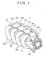
- FIG. 1 a perspective view of a synthetic resin intake manifold 1 that uses a welding structure according to the embodiment of the invention.
- This synthetic resin intake manifold 1 supplies intake air to an engine (not shown).
- an in-line four cylinder engine is employed as the engine.
- the synthetic resin intake manifold 1 is integrally provided with a surge tank 11 at an upstream side thereof. A downstream side of the synthetic resin intake manifold 1 is attached to the engine using an attachment use flange 12.
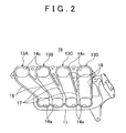
- the synthetic resin intake manifold 1 is formed from thermoplastic resin, and is provided, as shown in FIG. 2 , with respective intake passages 13A, 13B, 13C and 13D that correspond to four cylinders, not shown.
- Each intake passage 13A, 13B, 13C and 13D, as shown in FIG. 1 includes an upstream straight passage portion 14a (only one of these is shown in FIG. 1 ), a U-shaped passage portion 14b, and a downstream straight passage portion 14c.
- Each upstream straight passage portion 14a is separately connected at an upstream end thereof to the surge tank 11 and extends in a generally horizontal direction away from the engine side.
- the U-shaped passage portion 14b bends upwards in a generally U-shaped manner from a downstream end of the upstream straight passage portion 14a and has a downstream end that faces towards the engine side.
- the downstream straight passage portion 14c extends generally horizontally toward the engine side from the downstream end of the downstream straight passage portion 14c.
- the synthetic resin intake manifold 1 is divided into a synthetic resin passage structural member 15 (shown in FIG. 1 ) and a synthetic resin intake manifold body 16 that forms the rest of the synthetic resin intake manifold 1. With this configuration, as shown in FIG.
- a partition wall 17 is provided in a neighboring space between the neighboring intake passages 13A and 13B and partitions off the intake passages 13A and 13B from each other (the same description applies to the intake passages 13B and 13C, and 13C and 13D).
- the sections of the partition wall 17 that partition off and are directly contact with the intake passages 13A, 13B, 13C and 13D are not exposed to the outside.
- the synthetic resin intake manifold body 16 includes the surface tank 11, the attachment flange 12, and an engine side substantially semi-arc shaped cross section portion 18 (hereinafter referred to as the "engine side semi-arc shaped portion" for simplicity) that forms an engine side of the U-shaped passage portions 14b of the intake passages 13A, 13B, 13C and 13D.
- the synthetic resin passage structural member 15 is formed from an opposite-engine side substantially semi-arc shaped cross section portion which (i) forms a separateable portion of the U-shaped passage portions 14b of each of the intake passages 13A, 13B, 13C and 13D of the synthetic resin intake manifold 1 and which is (ii) positioned at the side of the U-shaped passage portion 14b of the intake passages 13A, 13B, 13C and 13D that is opposite to the engine.
- the synthetic resin passage structural member 15 is formed as a single integral unit and covers the engine side semi-arc shaped portion 18 of the U-shaped passage portions 14b of the intake passages 13A, 13B, 13C and 13D from the opposite engine side.
- the synthetic resin passage structural member 15 is welded to the engine side semi-arc shaped portion 18 of the U-shaped passage portion 14b of the intake passages 13A, 13B, 13C and 13D of the synthetic resin intake manifold body 16 along a joining line.
- This joining line has a loop shape (the joining line is the line that connects periphery walls of the intake passages 13A, 13B, 13C and 13D excluding the partition walls 17), as shown in FIG. 2 .
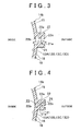
- the synthetic resin intake manifold body 16 and the synthetic resin passage structural member 15 are respectively provided with a body side joining flange 21 and a structural member side joining flange 22 that extend continuously along the joining line at an outside thereof.
- the body side joining flange 21, which corresponds to a first joining flange among the two joining flanges 21 and 22, is provided with a protrusion 21a that protrudes towards the structural member side joining flange 22, which corresponds to a second joining flange.
- the protrusion 21a protrudes at a substantially central position in an inward-outward direction of the joining line, and is formed continuously along the joining line.
- a welding protrusion 22a is provided on the structural member side joining flange 22.
- This welding protrusion 22a is formed continuously along the joining line and protrudes at a substantially central position in an inwards-outwards direction of the joining line towards the body side joining flange 21.
- the welding protrusion 22a is welded to the protrusion 21a.
- the structural member side joining flange 22 is also provided with inside and outside control walls 22b and 22c that respectively protrude toward the body side joining flange 21 at the inside and outside of the joining line with the welding protrusion 22a disposed therebetween.
- the inside and outside control walls 22b and 22c are provided continuously along the joining line.
- the synthetic resin passage structural member 15 (the opposite-engine side substantially arc-shaped cross section portion) is positioned and aligned along the joining line with respect to the engine side semi-arc shaped portion 18 of the U-shaped passage portion 14b of the intake passages 13A, 13B, 13C and 13D of the synthetic resin intake manifold body 16, as shown in FIG. 4 .
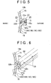
- an inside burr retaining groove 23 surrounded by the protrusion 21a of the body side joining flange 21 and the inside control wall 22b and the welding protrusion 22a of the structural member side joining flange 22 is formed at the inside of the joining line.
- This inside burr retaining groove 23 is formed continuously along the joining line.
- FIG. 5 shows a welded state of the body side joining flange 21 and the structural member side joining flange 22.
- the inside burr retaining groove 23 and the outside burr retaining groove 24 are provided to trap and retain this welding burr G.
- a dimension A of the inside burr retaining groove 23 is formed to be longer than a dimension B of the outside burr retaining groove 24.
- the dimension A of the inside burr retaining groove 23 in the inward-outward direction between the inside control wall 22b and the welding protrusion 22a is formed to be longer by a predetermined ratio (for example, a ratio of around 1:1.1 to 1:1.2) than the dimension B of the outside burr retaining groove 24 in the inward-outward direction between the outside control wall 22c and the welding protrusion 22a.
- a volume of the inside burr retaining groove 23 is set to be larger than a volume of the outside burr retaining groove 24 by a predetermined ratio.
- an inside wall surface of the engine side semi-arc shaped portion 18 of the U-shaped passage portion 14b of the intake passages 13A, 13B, 13C and 13D is positioned to be flush with an inside wall surface of the opposite-engine side substantially arc-shaped cross section portion (the inside edge surface of the inside control wall 22b) of the synthetic resin passage structural member 15 at the inside of the joining line.
- respective inward-outward direction widths of the body side joining flange 21 and the structural member side joining flange 22 are the same. Further, the length of the body side joining flange 21 and the structural member side joining flange 22 in the outward direction of the joining line from the inside wall surfaces that are flush with each other is the same.
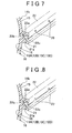
- confirmation-use openings 25 are provided for confirming a state of progress of welding of the joining flanges 21 and 22 at the joining line as shown in FIG. 6 (only two are shown in the drawing). These confirmation-use openings 25 are provided in a tip end of the outside control wall 22c (at positions that are as far as possible from the welding portion of the protrusion 21a and the welding protrusion 22a). These confirmation-use openings 25 are formed as notches with a generally inverted V-shape, and are positioned at predetermined intervals along the joining line.
- the synthetic resin passage structural member 15 (the opposite-engine side substantially arc-shaped cross section portion) is welded to the engine side semi-arc shaped portion 18 of the U-shaped passage portion 14b of the intake passages 13A, 13B, 13C and 13D of the synthetic resin intake manifold body 16
- the welding protrusion 22a of the structural member side joining flange 22 is vibration welded to the protrusion 21a of the body side joining flange 21, whereby the welding burr G is formed.
- a protrusion timing at which the welding burr G overflows and protrudes from the inside and outside burr retaining grooves 23 and 24 towards the inside and outside is different for each side due to the difference in the volumes of the inside and outside burr retaining grooves 23 and 24. More specifically, the welding burr G from the outside burr retaining groove 24 overflows and protrudes to the outside prior to when the welding burr G from the inside burr retaining groove 23 overflows and protrudes to the inside.
- the synthetic resin passage structural member 15 (the opposite-engine side substantially arc-shaped cross section portion) is positioned and aligned along the joining line with respect to the engine side semi-arc shaped portion 18 of the U-shaped passage portion 14b of the intake passages 13A, 13B, 13C and 13D of the synthetic resin intake manifold body 16 prior to welding.
- the dimension A in the inward-outward direction between the inside control wall 22b and the welding protrusion 22a of the inside burr retaining groove 23 is set to be longer than the dimension B in the inward-outward direction between the outside control wall 22c and the welding protrusion 22a of the outside burr retaining groove 24.
- the dimensional difference (A - B) in the inward-outward direction of the inside and outside burr retaining grooves 23 and 24 causes the respective welding burrs G that flow to the inside and outside of the joining line to flow such that: the welding burr G in the outside burr retaining groove 24 definitely overflows and protrudes to the outside prior to when the welding burr G in the inside burr retaining groove 23 overflows and protrudes to the inside. Accordingly, if welding is stopped when the welding burr G protrudes to the outside, it is possible to reliably inhibit protrusion of the welding burr G to the inside, which is extremely favorable from the point of view of reliably inhibiting worsening of intake air flow resistance.
- the confirmation-use openings 25 for confirming the state of progress of welding of the joining flanges 21 and 22 at the joining line are formed as the notches with the generally inverted V-shape and are provided in the tip end of the outside control wall 22c at the predetermined intervals in the joining line direction. Accordingly, even if an outflow amount of the welding burr G to the outside is small, it is possible to use the confirmation-use openings 25 to directly view the welding portion of the protrusion 21a and the welding protrusion 22a. This enables welding quality to be controlled efficiency.
- the synthetic resin passage structural member 15 when the synthetic resin passage structural member 15 is positioned and aligned along the joining line with respect to the engine side semi-arc shaped portion 18 of the U-shaped passage portion 14b of the intake passages 13A, 13B, 13C and 13D of the synthetic resin intake manifold body 16, the inside wall surface of the engine side semi-arc shaped portion 18 of the U-shaped passage portion 14b of the intake passages 13A, 13B, 13C and 13D is positioned to be flush with the inside wall surface of the opposite-engine side substantially arc-shaped cross section portion (the inside edge surface of the inside control wall 22b) of the synthetic resin passage structural member 15 at the inside of the joining line.
- the invention is not limited to the above described embodiment and includes a variety of other forms and modifications within its scope as defined by the appended claims.
- the confirmation-use openings 25 are formed as substantially inverted V-shaped notches in the tip end of the outside control wall 22c.
- confirmation-use openings 26 may be formed with a generally circular shape at predetermined intervals in the joining line direction in the vicinity of generally central points of the outside control wall 22c near to the welding portion of the protrusion 21a and the welding protrusion 22a.
- the confirmation-use openings 25 are formed as the substantially inverted V-shaped notches in the tip end of the outside control wall 22c.
- confirmation-use openings 27 may be formed as generally inverted U-shaped notches in the tip end of the outside control wall 22c. These confirmation-use openings 27 may be formed at predetermined intervals in the joining line direction. In this case, even if the outflow amount of the welding burr G to the outside is small, the confirmation-use openings 27 can be used to view even deeper toward the welding portion of the protrusion 21a and the welding protrusion 22a. Accordingly, welding quality can be controlled even more efficiently.
- the cutting operation for the generally U-shaped notches is easier to perform. Thus, this configuration is extremely favorable from the point of view of mass production.
- the synthetic resin passage structural member 15 just the opposite-engine side substantially arc-shaped cross section portion of the U-shaped passage portion 14b of the intake passages 13A, 13B, 13C and 13D is separate from the synthetic resin intake manifold body 1.
- This opposite-engine side substantially arc-shaped cross section portion is welded along the joining line to the engine side semi-arc shaped portion 18 of the U-shaped passage portion 14b of the intake passages 13A, 13B, 13C and 13D of the synthetic resin intake manifold body 16.
- the synthetic resin passage structural member that is separate from the synthetic resin intake manifold is not limited to that described above.
- the configuration may be such that the surge tank or the like is similarly divided with a substantially semi-arc shaped cross section, and vibration welded to the synthetic resin passage structural member body.
- the above embodiment describes an example in which the synthetic resin passage structural member 15 is vibration welded to the engine side semi-arc shaped portion 18 of the U-shaped passage portion 14b of the intake passages 13A, 13B, 13C and 13D of the synthetic resin intake manifold body 16.
- dielectric welding, hot plate welding, electromagnetic induction welding or hot wire welding may be used.
Landscapes
- Engineering & Computer Science (AREA)
- Mechanical Engineering (AREA)
- Chemical & Material Sciences (AREA)
- Combustion & Propulsion (AREA)
- General Engineering & Computer Science (AREA)
- Manufacturing & Machinery (AREA)
- Lining Or Joining Of Plastics Or The Like (AREA)
Claims (5)
- Schweißstruktur für einen Kunstharz-Ansaugkrümmer (1), aufweisend:ein Kunstharz-Leitungsstrukturelement (15), das zumindest einen Abschnitt des Kunstharz-Ansaugkrümmers (1) ausbildet; undeinen Kunstharz-Ansaugkrümmerkörper (16), mit dem das Kunstharz-Leitungsstrukturelement (15) entlang einer schleifenförmigen Verbindungslinie verschweißt ist,einen ersten Verbindungsflansch (12), der auf dem Kunstharz-Ansaugkrümmer (16) entlang der Verbindungslinie angeordnet ist;einen zweiten Verbindungsflansch (22), der auf dem Kunstharz-Leitungsstrukturelement (15) entlang der Verbindungslinie angeordnet ist;einen Vorsprung (21a), der auf dem ersten Verbindungsflansch (21) angeordnet ist und zum zweiten Verbindungsflansch (22) hin vorsteht;einen Schweißvorsprung (22a), der auf dem zweiten Verbindungsflansch (22) angeordnet ist, wobei der Schweißvorsprung (22a) zum ersten Verbindungsflansch (21) hin vorsteht und mit dem Vorsprung (21 a) verschweißt ist; undeine innere Kontrollwand (22b) und eine äußere Kontrollwand (22c), die jeweils zum ersten Verbindungsflansch (21) hin an einer Innenseite und an einer Außenseite der Verbindungslinie vorstehen, und die jeweils zu beiden Seiten des Schweißvorsprungs (22a) angeordnet sind, wobeidas Kunstharz-Leitungsstrukturelement (15) in Bezug auf den Kunstharz-Ansaugkrümmerkörper (16) entlang der Verbindungslinie vor dem Schweißvorgang positioniert und ausgerichtet wird, so dass ein Volumen einer innenseitigen Schweißgrat-Aufnahmenut (23), die durch den Vorsprung (21a) des ersten Verbindungsflansches (21) und die innere Kontrollwand (22b) des zweiten Verbindungsflansches (22) und den Schweißvorsprung (22a) des zweiten Verbindungsflansches (22) ausgebildet ist, so eingestellt ist, dass es größer ist als ein Volumen einer außenseitigen Schweißgrat-Aufnahmenut (24), die durch den Vorsprung (21a) des ersten Verbindungsflansches (21) und die äußere Kontrollwand (22c) des zweiten Verbindungsflansches (22) und den Schweißvorsprung (22a) des zweiten Verbindungsflansches (22) ausgebildet ist,dadurch gekennzeichnet, dassdie äußere Kontrollwand (22c) mit einer zu Bestätigungszwecken dienenden Öffnung (25, 26, 27), zum Bestätigen eines Verlaufsstatus des Schweißvorgangs des ersten und des zweiten Verbindungsflansches (21, 22) an der Verbindungslinie, versehen ist.
- Schweißstruktur für den Kunstharz-Ansaugkrümmer (1) nach Anspruch 1, wobei das Kunstharz-Leitungsstrukturelement (15) in Bezug auf den Kunstharz-Ansaugkrümmerkörper (16) entlang der Verbindungslinie vor dem Schweißvorgang derart positioniert und ausgerichtet wird, dass eine Abmessung (B) der innenseitigen Schweißgrat-Aufnahmenut (23) in einer von innen nach außen verlaufenden Richtung zwischen der inneren Kontrollwand (22b) und dem Schweißvorsprung (22a) so eingestellt ist, dass sie länger ist als eine Abmessung (A) der außenseitigen Schweißgrat-Aufnahmenut (24) in der von innen nach außen verlaufenden Richtung zwischen der äußeren Kontrollwand (22b) und dem Schweißvorsprung (22a).
- Schweißstruktur für den Kunstharz-Ansaugkrümmer (1) nach Anspruch 1, wobei die zu Bestätigungszwecken dienende Öffnung (25) als eine V-förmige Kerbe an einer abschließenden Kante der äußeren Kontrollwand (22c) ausgebildet ist.
- Schweißstruktur für den Kunstharz-Ansaugkrümmer (1) nach Anspruch 1, wobei die zu Bestätigungszwecken dienende Öffnung (26) in der äußeren Kontrollwand (22c) angeordnet ist, und wobei die zu Bestätigungszwecken dienende Öffnung (26) kreisrund ausgeschnitten ist und in vorher festgelegten Intervallen in Richtung der Verbindungslinie in der Nähe des Mittelpunkts der äußeren Kontrollwand (22c) angeordnet ist.
- Schweißstruktur für den Kunstharz-Ansaugkrümmer (1) nach Anspruch 1, wobei die zu Bestätigungszwecken dienende Öffnung (27) als eine U-förmige Kerbe an einer abschließenden Kante der äußeren Kontrollwand (22c) ausgebildet ist.
Applications Claiming Priority (2)
| Application Number | Priority Date | Filing Date | Title |
|---|---|---|---|
| JP2004311621A JP2006125227A (ja) | 2004-10-27 | 2004-10-27 | 合成樹脂製吸気マニホールドの溶着構造 |
| PCT/IB2005/003139 WO2006046102A2 (en) | 2004-10-27 | 2005-10-21 | Welding structure for synthetic resin intake manifold |
Publications (2)
| Publication Number | Publication Date |
|---|---|
| EP1817154A2 EP1817154A2 (de) | 2007-08-15 |
| EP1817154B1 true EP1817154B1 (de) | 2011-01-12 |
Family
ID=35872181
Family Applications (1)
| Application Number | Title | Priority Date | Filing Date |
|---|---|---|---|
| EP05818845A Expired - Lifetime EP1817154B1 (de) | 2004-10-27 | 2005-10-21 | Schweissstruktur für ein saugrohr aus synthetischem harz |
Country Status (6)
| Country | Link |
|---|---|
| US (1) | US7174873B2 (de) |
| EP (1) | EP1817154B1 (de) |
| JP (1) | JP2006125227A (de) |
| CN (1) | CN101124396A (de) |
| DE (1) | DE602005025916D1 (de) |
| WO (1) | WO2006046102A2 (de) |
Families Citing this family (21)
| Publication number | Priority date | Publication date | Assignee | Title |
|---|---|---|---|---|
| US8349122B2 (en) * | 2006-05-24 | 2013-01-08 | Heateflex Corporation | Fusion welding fittings with weld bead cover |
| DE102007026826A1 (de) | 2007-06-06 | 2008-12-11 | Mann + Hummel Gmbh | Ansaugsystem |
| USD580457S1 (en) * | 2007-06-12 | 2008-11-11 | C & L Performance, Inc. | Engine intake manifold |
| JP4976245B2 (ja) * | 2007-09-11 | 2012-07-18 | 愛三工業株式会社 | 樹脂成形体 |
| JP2010083068A (ja) * | 2008-10-01 | 2010-04-15 | Polyplastics Co | 溶着構造、溶着体、及びクリープ破壊寿命向上方法 |
| JP5636328B2 (ja) * | 2011-04-05 | 2014-12-03 | 本田技研工業株式会社 | 接合管 |
| JP5850643B2 (ja) * | 2011-05-17 | 2016-02-03 | 株式会社ニフコ | レゾネーター |
| CN104093545B (zh) | 2011-05-23 | 2016-07-27 | 巴斯夫欧洲公司 | 用于包括热塑性材料的物品的摩擦焊接接头 |
| DE102011089092A1 (de) * | 2011-12-19 | 2013-06-20 | Behr Gmbh & Co. Kg | Gehäuse insbesondere für eine Kraftfahrzeugklimaanlage |
| KR101888639B1 (ko) * | 2012-04-13 | 2018-08-14 | 한온시스템 주식회사 | 리저브 탱크 일체형 팬 쉬라우드 어셈블리 |
| EP2852489A4 (de) | 2012-05-23 | 2016-05-11 | Basf Se | Reibschweissverbindung für einen artikel mit einem thermoplastischen material |
| DE102012212110A1 (de) * | 2012-07-11 | 2014-01-16 | Mahle International Gmbh | Frischluftversorgungseinrichtung und Herstellungsverfahren |
| JP5870900B2 (ja) * | 2012-10-31 | 2016-03-01 | トヨタ自動車株式会社 | 吸気マニホールド |
| US8524344B1 (en) * | 2012-11-07 | 2013-09-03 | GM Global Technology Operations PLLC | Polymeric vessel |
| EP3406889A1 (de) * | 2017-05-22 | 2018-11-28 | MANN+HUMMEL GmbH | Gasgeräuschdämpfer im ansaugsystem eines verbrennungsmotors und methode um einen solchen dämpfer herzustellen |
| JP6663409B2 (ja) * | 2017-11-09 | 2020-03-11 | 株式会社Subaru | 連結構造 |
| JP2020002828A (ja) * | 2018-06-26 | 2020-01-09 | トヨタ紡織株式会社 | 内燃機関の吸気ダクト |
| JP7107086B2 (ja) * | 2018-08-13 | 2022-07-27 | トヨタ紡織株式会社 | 内燃機関の吸気ダクト |
| JP2021017840A (ja) * | 2019-07-19 | 2021-02-15 | トヨタ紡織株式会社 | 内燃機関の吸気ダクト |
| DE202019105247U1 (de) * | 2019-09-23 | 2021-01-04 | Elringklinger Ag | Abdeckung für Kraftfahrzeugbauteil |
| JP2025110689A (ja) * | 2024-01-16 | 2025-07-29 | 株式会社アイシン | マニホールドおよびマニホールドの製造方法 |
Family Cites Families (21)
| Publication number | Priority date | Publication date | Assignee | Title |
|---|---|---|---|---|
| GB839745A (en) | 1955-12-20 | 1960-06-29 | Evered & Co Ltd | Improvements in or relating to pipe joints |
| JPS6390063A (ja) | 1986-10-02 | 1988-04-20 | Nec Corp | 磁気デイスク制御装置 |
| JPS6390063U (de) * | 1986-12-01 | 1988-06-11 | ||
| GB2279035B (en) * | 1991-01-22 | 1995-06-07 | Rover Group | Fabrication of an internal combustion engine inlet manifold |
| JP3211592B2 (ja) | 1994-11-21 | 2001-09-25 | トヨタ自動車株式会社 | 樹脂製品の製造方法 |
| JPH09174697A (ja) * | 1995-12-28 | 1997-07-08 | Excel Kk | 樹脂製中空体とその製造方法 |
| US6021753A (en) * | 1996-07-03 | 2000-02-08 | Ford Global Technologies, Inc. | Adhesively bonded plastic automotive air intake assembly |
| JP3218985B2 (ja) * | 1996-08-30 | 2001-10-15 | トヨタ自動車株式会社 | 樹脂製中空体 |
| JP3019838B2 (ja) | 1998-02-04 | 2000-03-13 | トヨタ自動車株式会社 | 仕切板付きタンク |
| DE19820198B4 (de) * | 1998-05-06 | 2004-02-19 | Branson Ultraschall Niederlassung Der Emerson Technologies Gmbh & Co | Vorrichtung zum Verschweißen großflächiger Spritzgußbauteile aus Kunststoff |
| JP3777262B2 (ja) * | 1998-12-16 | 2006-05-24 | 日信工業株式会社 | 樹脂製部品 |
| DE19909850A1 (de) * | 1999-03-08 | 2000-09-14 | Mahle Filtersysteme Gmbh | Sauganlage für eine Brennkraftmaschine |
| US6447866B1 (en) * | 1999-12-23 | 2002-09-10 | Honeywell International Inc. | Frictionally welded thermoplastic articles having improved strength |
| JP3754590B2 (ja) * | 2000-02-16 | 2006-03-15 | 本田技研工業株式会社 | 振動溶着方法における被振動溶着部の溶着確認方法 |
| JP2002070672A (ja) * | 2000-08-31 | 2002-03-08 | Keihin Corp | 車両用吸気マニホールドおよびその製造方法 |
| JP3894715B2 (ja) * | 2000-09-11 | 2007-03-22 | 株式会社ケーヒン | 吸気通路構造体の溶着構造 |
| JP2002283455A (ja) * | 2001-03-26 | 2002-10-03 | Kyosan Denki Co Ltd | 樹脂部品の接合構造 |
| JP2002364469A (ja) * | 2001-06-04 | 2002-12-18 | Keihin Corp | 車両用吸気マニホールドの製造方法 |
| DE10300809A1 (de) | 2003-01-13 | 2004-07-22 | Seeber Ag & Co. Kg | Ansaugeinrichtung für eine Brennkraftmaschine |
| US6988478B2 (en) * | 2003-04-09 | 2006-01-24 | Aisan Kogyo Kabushiki Kaisha | Resin intake manifold |
| JP4405206B2 (ja) * | 2003-08-08 | 2010-01-27 | 株式会社Roki | 仕切り部材付きケース |
-
2004
- 2004-10-27 JP JP2004311621A patent/JP2006125227A/ja active Pending
-
2005
- 2005-10-21 DE DE602005025916T patent/DE602005025916D1/de not_active Expired - Lifetime
- 2005-10-21 EP EP05818845A patent/EP1817154B1/de not_active Expired - Lifetime
- 2005-10-21 WO PCT/IB2005/003139 patent/WO2006046102A2/en not_active Ceased
- 2005-10-21 CN CNA2005800368968A patent/CN101124396A/zh active Pending
- 2005-10-24 US US11/256,115 patent/US7174873B2/en not_active Expired - Fee Related
Also Published As
| Publication number | Publication date |
|---|---|
| DE602005025916D1 (de) | 2011-02-24 |
| WO2006046102A2 (en) | 2006-05-04 |
| EP1817154A2 (de) | 2007-08-15 |
| JP2006125227A (ja) | 2006-05-18 |
| WO2006046102A3 (en) | 2006-08-24 |
| US20060086334A1 (en) | 2006-04-27 |
| CN101124396A (zh) | 2008-02-13 |
| US7174873B2 (en) | 2007-02-13 |
Similar Documents
| Publication | Publication Date | Title |
|---|---|---|
| EP1817154B1 (de) | Schweissstruktur für ein saugrohr aus synthetischem harz | |
| JP3429143B2 (ja) | 排ガス冷却用の熱伝達装置 | |
| EP1431561B1 (de) | Zylinderkopf einer Brennkraftmaschine und ein Verfahren selbigen herzustellen | |
| EP3258147B1 (de) | Rückschlagventile | |
| WO2016079979A1 (ja) | オイルストレーナ | |
| EP2211120B1 (de) | HVAC-System, das eine Geräuschminderungsfunktion beinhaltet | |
| EP3527355B1 (de) | Schweissrippenstruktur | |
| JP2002139290A (ja) | モジュールタイプ熱交換器およびその製造方法 | |
| JP4726638B2 (ja) | オイルストレーナ | |
| JP6033573B2 (ja) | ステーター用インシュレーター | |
| JP2024518234A (ja) | 分流器及びそれを有する冷却システム | |
| JP2008208770A (ja) | インテークマニホールド構造 | |
| JP2009243563A (ja) | 中空部品へのパイプ接続構造 | |
| JP5046805B2 (ja) | オイルストレーナ | |
| JP4172381B2 (ja) | 内燃機関の吸気装置及びその製造方法 | |
| JP6561480B2 (ja) | エンジンの吸気ポート構造 | |
| JPWO2003052337A1 (ja) | チューブ、チューブの製造方法、熱交換器用チューブ、熱交換器用チューブの製造方法、熱交換器、熱交換器の製造方法 | |
| JP2010164006A (ja) | シリンダブロックの冷却構造 | |
| JPH10146860A (ja) | 樹脂ケーシングおよびその製造方法 | |
| JP2005114199A (ja) | 熱交換器のヘッダおよびその製造方法 | |
| JP4226435B2 (ja) | 吸気ポート用の仕切り板、吸気ポート成形用砂中子およびシリンダヘッド | |
| JP2026003999A (ja) | マフラ | |
| EP0114618A2 (de) | Gegossene Luftansauganlage für Brennkraftmaschinen, insbesondere in Druckgussausführung | |
| JP3135768B2 (ja) | 吸気マニホールド | |
| JP2006308144A (ja) | 熱交換器のヘッダタンクとチューブとの接合構造 |
Legal Events
| Date | Code | Title | Description |
|---|---|---|---|
| PUAI | Public reference made under article 153(3) epc to a published international application that has entered the european phase |
Free format text: ORIGINAL CODE: 0009012 |
|
| 17P | Request for examination filed |
Effective date: 20070418 |
|
| AK | Designated contracting states |
Kind code of ref document: A2 Designated state(s): DE FR GB IT |
|
| DAX | Request for extension of the european patent (deleted) | ||
| RBV | Designated contracting states (corrected) |
Designated state(s): DE FR GB IT |
|
| 17Q | First examination report despatched |
Effective date: 20100401 |
|
| GRAP | Despatch of communication of intention to grant a patent |
Free format text: ORIGINAL CODE: EPIDOSNIGR1 |
|
| GRAS | Grant fee paid |
Free format text: ORIGINAL CODE: EPIDOSNIGR3 |
|
| GRAA | (expected) grant |
Free format text: ORIGINAL CODE: 0009210 |
|
| AK | Designated contracting states |
Kind code of ref document: B1 Designated state(s): DE FR GB IT |
|
| REG | Reference to a national code |
Ref country code: GB Ref legal event code: FG4D |
|
| REF | Corresponds to: |
Ref document number: 602005025916 Country of ref document: DE Date of ref document: 20110224 Kind code of ref document: P |
|
| REG | Reference to a national code |
Ref country code: DE Ref legal event code: R096 Ref document number: 602005025916 Country of ref document: DE Effective date: 20110224 |
|
| PLBE | No opposition filed within time limit |
Free format text: ORIGINAL CODE: 0009261 |
|
| STAA | Information on the status of an ep patent application or granted ep patent |
Free format text: STATUS: NO OPPOSITION FILED WITHIN TIME LIMIT |
|
| 26N | No opposition filed |
Effective date: 20111013 |
|
| REG | Reference to a national code |
Ref country code: DE Ref legal event code: R097 Ref document number: 602005025916 Country of ref document: DE Effective date: 20111013 |
|
| REG | Reference to a national code |
Ref country code: GB Ref legal event code: 746 Effective date: 20130717 |
|
| REG | Reference to a national code |
Ref country code: DE Ref legal event code: R084 Ref document number: 602005025916 Country of ref document: DE Effective date: 20130717 |
|
| REG | Reference to a national code |
Ref country code: FR Ref legal event code: PLFP Year of fee payment: 12 |
|
| PGFP | Annual fee paid to national office [announced via postgrant information from national office to epo] |
Ref country code: FR Payment date: 20160919 Year of fee payment: 12 |
|
| PGFP | Annual fee paid to national office [announced via postgrant information from national office to epo] |
Ref country code: GB Payment date: 20161019 Year of fee payment: 12 Ref country code: DE Payment date: 20161018 Year of fee payment: 12 |
|
| PGFP | Annual fee paid to national office [announced via postgrant information from national office to epo] |
Ref country code: IT Payment date: 20161024 Year of fee payment: 12 |
|
| REG | Reference to a national code |
Ref country code: DE Ref legal event code: R119 Ref document number: 602005025916 Country of ref document: DE |
|
| GBPC | Gb: european patent ceased through non-payment of renewal fee |
Effective date: 20171021 |
|
| REG | Reference to a national code |
Ref country code: FR Ref legal event code: ST Effective date: 20180629 |
|
| PG25 | Lapsed in a contracting state [announced via postgrant information from national office to epo] |
Ref country code: DE Free format text: LAPSE BECAUSE OF NON-PAYMENT OF DUE FEES Effective date: 20180501 Ref country code: GB Free format text: LAPSE BECAUSE OF NON-PAYMENT OF DUE FEES Effective date: 20171021 |
|
| PG25 | Lapsed in a contracting state [announced via postgrant information from national office to epo] |
Ref country code: FR Free format text: LAPSE BECAUSE OF NON-PAYMENT OF DUE FEES Effective date: 20171031 |
|
| PG25 | Lapsed in a contracting state [announced via postgrant information from national office to epo] |
Ref country code: IT Free format text: LAPSE BECAUSE OF NON-PAYMENT OF DUE FEES Effective date: 20171021 |