EP1810817B1 - Verfahren und Vorrichtung zur Herstellung einer Form sowie Verfahren und Vorrichtung zur Herstellung von Kunststofflinsen - Google Patents
Verfahren und Vorrichtung zur Herstellung einer Form sowie Verfahren und Vorrichtung zur Herstellung von Kunststofflinsen Download PDFInfo
- Publication number
- EP1810817B1 EP1810817B1 EP07001026A EP07001026A EP1810817B1 EP 1810817 B1 EP1810817 B1 EP 1810817B1 EP 07001026 A EP07001026 A EP 07001026A EP 07001026 A EP07001026 A EP 07001026A EP 1810817 B1 EP1810817 B1 EP 1810817B1
- Authority
- EP
- European Patent Office
- Prior art keywords
- tab
- injection port
- tape
- molding die
- forming
- Prior art date
- Legal status (The legal status is an assumption and is not a legal conclusion. Google has not performed a legal analysis and makes no representation as to the accuracy of the status listed.)
- Expired - Fee Related
Links
Images


Classifications
-
- B—PERFORMING OPERATIONS; TRANSPORTING
- B29—WORKING OF PLASTICS; WORKING OF SUBSTANCES IN A PLASTIC STATE IN GENERAL
- B29D—PRODUCING PARTICULAR ARTICLES FROM PLASTICS OR FROM SUBSTANCES IN A PLASTIC STATE
- B29D11/00—Producing optical elements, e.g. lenses or prisms
-
- B—PERFORMING OPERATIONS; TRANSPORTING
- B29—WORKING OF PLASTICS; WORKING OF SUBSTANCES IN A PLASTIC STATE IN GENERAL
- B29D—PRODUCING PARTICULAR ARTICLES FROM PLASTICS OR FROM SUBSTANCES IN A PLASTIC STATE
- B29D11/00—Producing optical elements, e.g. lenses or prisms
- B29D11/00009—Production of simple or compound lenses
-
- B—PERFORMING OPERATIONS; TRANSPORTING
- B29—WORKING OF PLASTICS; WORKING OF SUBSTANCES IN A PLASTIC STATE IN GENERAL
- B29C—SHAPING OR JOINING OF PLASTICS; SHAPING OF MATERIAL IN A PLASTIC STATE, NOT OTHERWISE PROVIDED FOR; AFTER-TREATMENT OF THE SHAPED PRODUCTS, e.g. REPAIRING
- B29C33/00—Moulds or cores; Details thereof or accessories therefor
- B29C33/0077—Moulds or cores; Details thereof or accessories therefor characterised by the configuration of the mould filling gate ; accessories for connecting the mould filling gate with the filling spout
-
- B—PERFORMING OPERATIONS; TRANSPORTING
- B29—WORKING OF PLASTICS; WORKING OF SUBSTANCES IN A PLASTIC STATE IN GENERAL
- B29C—SHAPING OR JOINING OF PLASTICS; SHAPING OF MATERIAL IN A PLASTIC STATE, NOT OTHERWISE PROVIDED FOR; AFTER-TREATMENT OF THE SHAPED PRODUCTS, e.g. REPAIRING
- B29C33/00—Moulds or cores; Details thereof or accessories therefor
- B29C33/30—Mounting, exchanging or centering
-
- B—PERFORMING OPERATIONS; TRANSPORTING
- B29—WORKING OF PLASTICS; WORKING OF SUBSTANCES IN A PLASTIC STATE IN GENERAL
- B29C—SHAPING OR JOINING OF PLASTICS; SHAPING OF MATERIAL IN A PLASTIC STATE, NOT OTHERWISE PROVIDED FOR; AFTER-TREATMENT OF THE SHAPED PRODUCTS, e.g. REPAIRING
- B29C33/00—Moulds or cores; Details thereof or accessories therefor
- B29C33/38—Moulds or cores; Details thereof or accessories therefor characterised by the material or the manufacturing process
-
- B—PERFORMING OPERATIONS; TRANSPORTING
- B29—WORKING OF PLASTICS; WORKING OF SUBSTANCES IN A PLASTIC STATE IN GENERAL
- B29C—SHAPING OR JOINING OF PLASTICS; SHAPING OF MATERIAL IN A PLASTIC STATE, NOT OTHERWISE PROVIDED FOR; AFTER-TREATMENT OF THE SHAPED PRODUCTS, e.g. REPAIRING
- B29C39/00—Shaping by casting, i.e. introducing the moulding material into a mould or between confining surfaces without significant moulding pressure; Apparatus therefor
- B29C39/22—Component parts, details or accessories; Auxiliary operations
- B29C39/24—Feeding the material into the mould
-
- B—PERFORMING OPERATIONS; TRANSPORTING
- B29—WORKING OF PLASTICS; WORKING OF SUBSTANCES IN A PLASTIC STATE IN GENERAL
- B29D—PRODUCING PARTICULAR ARTICLES FROM PLASTICS OR FROM SUBSTANCES IN A PLASTIC STATE
- B29D11/00—Producing optical elements, e.g. lenses or prisms
- B29D11/00009—Production of simple or compound lenses
- B29D11/00413—Production of simple or compound lenses made by moulding between two mould parts which are not in direct contact with one another, e.g. comprising a seal between or on the edges
-
- B—PERFORMING OPERATIONS; TRANSPORTING
- B29—WORKING OF PLASTICS; WORKING OF SUBSTANCES IN A PLASTIC STATE IN GENERAL
- B29D—PRODUCING PARTICULAR ARTICLES FROM PLASTICS OR FROM SUBSTANCES IN A PLASTIC STATE
- B29D11/00—Producing optical elements, e.g. lenses or prisms
- B29D11/00009—Production of simple or compound lenses
- B29D11/00432—Auxiliary operations, e.g. machines for filling the moulds
-
- B—PERFORMING OPERATIONS; TRANSPORTING
- B29—WORKING OF PLASTICS; WORKING OF SUBSTANCES IN A PLASTIC STATE IN GENERAL
- B29C—SHAPING OR JOINING OF PLASTICS; SHAPING OF MATERIAL IN A PLASTIC STATE, NOT OTHERWISE PROVIDED FOR; AFTER-TREATMENT OF THE SHAPED PRODUCTS, e.g. REPAIRING
- B29C39/00—Shaping by casting, i.e. introducing the moulding material into a mould or between confining surfaces without significant moulding pressure; Apparatus therefor
- B29C39/02—Shaping by casting, i.e. introducing the moulding material into a mould or between confining surfaces without significant moulding pressure; Apparatus therefor for making articles of definite length, i.e. discrete articles
-
- B—PERFORMING OPERATIONS; TRANSPORTING
- B29—WORKING OF PLASTICS; WORKING OF SUBSTANCES IN A PLASTIC STATE IN GENERAL
- B29C—SHAPING OR JOINING OF PLASTICS; SHAPING OF MATERIAL IN A PLASTIC STATE, NOT OTHERWISE PROVIDED FOR; AFTER-TREATMENT OF THE SHAPED PRODUCTS, e.g. REPAIRING
- B29C39/00—Shaping by casting, i.e. introducing the moulding material into a mould or between confining surfaces without significant moulding pressure; Apparatus therefor
- B29C39/22—Component parts, details or accessories; Auxiliary operations
- B29C39/26—Moulds or cores
-
- B—PERFORMING OPERATIONS; TRANSPORTING
- B29—WORKING OF PLASTICS; WORKING OF SUBSTANCES IN A PLASTIC STATE IN GENERAL
- B29L—INDEXING SCHEME ASSOCIATED WITH SUBCLASS B29C, RELATING TO PARTICULAR ARTICLES
- B29L2011/00—Optical elements, e.g. lenses, prisms
- B29L2011/0016—Lenses
Definitions
- the present invention relates to a method of forming a mold, a forming apparatus thereof, a method of manufacturing a plastic lens, and a manufacturing apparatus thereof.
- a device including: a washing device for washing a first mold for forming a convex surface of a lens and a second mold for forming a concave surface of a lens; a forming apparatus for a mold for arranging the first molding die and the second molding die, which have been washed with the washing device, so that the first molding die and the second molding die oppose each other with a predetermined distance therebetween, and for winding an adhesive tape around peripheral surfaces of those molding dies; and a resin injection device for injecting a resin material into a cavity of the mold formed by the forming apparatus, which is formed by the tape, the first molding die, and the second molding die.
- an injection port through which the nozzle can be inserted and through which air is let out of the mold when the resin material is injected through the nozzle is necessary.
- the injection port is formed by blowing heat-compressed air to the tape wound around the peripheral surfaces of the pair of molding dies as disclosed in JP 09-85754 A .
- a circular injection port is formed by arranging a heat-compressed air ejecting tube at a predetermined position opposing the tape wound around the peripheral surfaces of the pair of molding dies, and blowing the heat-compressed air against the tape from an end opening of the ejection tube.
- the resin injection device When the injection port is formed on the tape by the forming apparatus for a mold, the resin injection device is activated. First, the nozzle is inserted into the injection port and the resin material is filled into the cavity through the nozzle. The injection port needs to be sealed so that the resin material does not leak from the injection port after the resin material is filled in the cavity.
- the injection port is sealed by irradiating ultraviolet rays to cure the resin after an ultraviolet-curable resin is applied to the injection port as disclosed in JP 06-155481 A .
- the heat-compressed air is blown against the tape wound around the peripheral surfaces of the pair of molding dies to bore the injection port, so a base material of the tape or a foreign matter of an adhesive or the like blown by the compressed air enters the cavity.
- the injection port is entirely sealed with the ultraviolet-curable resin and is cured by irradiating the ultraviolet rays to the resin in order to seal the injection port.
- the injection port is formed in a large circular shape or in an elliptical annular shape in order that the nozzle can be inserted therethrough and that air within the cavity can be let out, so a large amount of expensive ultraviolet-curable resin is necessary.
- JP 06-155481 A there is a problem that manufacturing cost for the plastic lens becomes high.
- JP 2003-231135 discloses a method of forming a mold according to the preamble of claim 1, and a mold forming apparatus according to the preamble of claim 5.
- an injection port is created by non circular cut-outs to form tabs. After the needle is retrated, the tabs return to their original position to close the gate.
- the object of the invention is to provide a method of forming a mold, a forming apparatus thereof, a method of manufacturing a plastic lens, and a manufacturing apparatus thereof, which are capable of suppressing manufacturing cost while maintaining favorable appearance of the plastic lens.
- This object is achieved by a method of forming a mold according to claim 1, a method of forming a plastic lens according to claim 3, a mold forming apparatus according to claim 5, and a manufacturing apparatus for a plastic lens according to claim 6.
- a portion of the tape is non-circularly cut out through cutting or the like to form the tab non-circularly. Because the tab is formed non-circularly, the tab is integrated with a portion of the tape other than the tab and is bendable with the connection portion as a center. A large injection port may be formed by depressing the tab into the mold.
- the injection port is formed by using the non-circular tab, so the amount of processing chips or the like of a base material which are produced at a time of forming the injection port is extremely small as compared with the past case where the injection port has been formed circularly. Accordingly, the processing chips of the base material hardly enters the mold formed by winding the tape around the peripheral surfaces of the first molding die and the second molding die, so when a plastic lens is manufactured using this mold, appearance thereof does not deteriorate.
- a sealing material for sealing the injection port only needs to be provided on the periphery of the tab, so a usage amount of an expensive sealing material can be made smaller as compared with the past example where the circular injection port has been sealed over an entire surface. Thus, the manufacturing cost of the plastic lens can be suppressed.
- the winding is performed on the tape around peripheral surfaces of the first molding die and the second molding die after forming the tab.
- the injection port is formed on the tape before the tape is wound around the peripheral surfaces of the first molding die and the second molding die, so the processing chips or the like of the base material, which is produced when forming the injection port, does not enter the mold.
- the method of forming a mold according to the invention employs a structure, in which the injection port includes an injection port main body and a tab for sealing the injection port main body; the tab forming includes: forming the tab for sealing the injection port main body formed in advance; and superimposing a tape-like injection port forming portion having the injection port main body formed in advance, onto the tab; the tape superimposing includes positioning the injection port main body formed to have an area smaller than the area of the tab so that the injection port main body is positioned above the tab; and the tape winding includes winding the tape around the peripheral surfaces of the first molding die and the second molding die so that both end portions of the tape are superimposed on each other and that the tab is exposed.
- the mold forming apparatus has a structure including: a device for forming an injection port main body having an area smaller than the area of the tab, on another end of the tape; and a tape winding device for superimposing both end portions of the tape so that the injection port main body is positioned above the tab and for winding the tape around the peripheral surfaces of the first molding die and the second molding die.
- the tape on which the tab is formed in the tab forming is wound around the peripheral surfaces of the first molding die and the second molding die in the tape winding so that both ends thereof are superimposed on each other and that the tab is exposed.
- the injection port main body is formed on the tab (i.e., outer side of the mold) in the tab forming.
- the mold thus formed has the tab formed non-circularly, so the tab is integrated with the portion of the tape other than the tab and is bendable with the connection portion as a center.
- a large opening continuous with the injection port main body is formed by depressing the tab into the mold, whereby the resin material for forming the plastic lens is injected into the mold through this space.
- the tab When a fluid level of the resin material injected into the mold rises, the tab also rises along with the rise of the fluid level of the resin material, and further, a lower end portion of the tab also rises due to elasticity of the tab, whereby the injection port main body is eventually sealed with the tab.
- the tab is formed on the tape before the tape is wound around the peripheral surfaces of the first molding die and the second molding die, and the injection port main body is formed in the tape-like injection port forming portion.
- the processing chips or the like of the base material of the tape which is produced when forming the tab or the injection port main body, does not enter the mold.
- the tab eventually seals the injection port main body due to the rise of the resin material for forming the plastic lens injected into the mold. Accordingly, an expensive sealing material is not necessary for sealing the injection port main body, whereby the manufacturing cost of the plastic lens can be suppressed.
- the injection port forming portion is formed continuously with the end portion of the tape; and the injection port main body the forming and the tab forming are carried out substantially at the same time.
- the injection port forming portion is formed continuously with the tape, so the injection port forming portion and the tape can be formed of a single tape, thereby increasing processing efficiency. Further, the injection port forming portion is formed on the tape before the tape is wound around the peripheral surfaces of the first molding die and the second molding die, so the processing chips or the like of the base material of the tape does not enter the mold.
- a method of forming a plastic lens according to the invention includes, after forming a mold by the above recited method, depressing the tab through a nozzle and injecting a resin material for forming a plastic lens into the mold from an injection port from the nozzle.
- a manufacturing apparatus for a plastic lens according to the invention includes the mold forming apparatus and a resin injection device having a nozzle for depressing the tab, the device injecting the resin material for forming a plastic lens into the mold from the injection port through the nozzle.
- the tab is depressed into the mold by the nozzle in the resin injecting.
- a large space continuous with the injection port is formed by the depressing of the tab.
- a tip of the nozzle is positioned inside the mold, and the resin material for forming the plastic lens is injected into the mold from the tip of the nozzle in that state.
- the nozzle is pulled out of the mold when a predetermined amount of the resin material for forming the plastic lens is injected into the mold.
- the bent tab is displaced toward its original position (position of the tab before being depressed by the nozzle) owing to the elasticity or buoyancy thereof, and eventually, the tab seals the injection port.
- a manufacturing method of a plastic lens which can achieve the above-mentioned effects, can be provided.
- the nozzle for injecting the resin material for forming the plastic lens is used as a component for depressing the tab into the mold, resulting in a mutual use of the component.
- a device for drawing back and restoring the tab depressed by the nozzle to its original position by sucking the tab it is preferable to include a device for drawing back and restoring the tab depressed by the nozzle to its original position by sucking the tab.
- the tab is forcibly restored to a position at which the injection port is sealed in the tab restoring step after the resin material for forming the plastic lens is injected into the mold.
- the tab can be positively restored to its original position before being depressed irrespective of a presence/absence of the elasticity of the tab, whereby the sealing of the injection port can be performed positively.
- a plastic lens can be manufactured with a favorable precision.
- the drawing back and restoring of the tab is preferably carried out by sucking the tab.
- the manufacturing apparatus for a plastic lens includes a tab drawing back and restoring device for restoring the tab depressed by the nozzle to its original position by sucking the tab.
- the tab is forcibly restored to a position at which the injection port is sealed in the tab restoring step after the resin material for forming the plastic lens is injected into the mold.
- the tab can be positively restored to its original position before being depressed irrespective of a presence/absence of the elasticity of the tab, whereby the sealing of the injection port can be performed positively.
- a plastic lens can be manufactured with a favorable precision.
- the manufacturing apparatus for a plastic lens it is preferable to include a device for sealing the injection port.
- the resin in a case where a gap is formed between the periphery of the tab and a portion of the tape in the vicinity thereof, the resin can be positively prevented from leaking from the injection port by sealing the gap by appropriate ways.
- FIGS. 1 5B A first exemplary embodiment, which is not part of the invention, is described with reference to FIGS. 1 5B .
- a plastic lens manufacturing apparatus includes a mold forming apparatus.
- FIGS. 1 and 2 A schematic configuration of the mold forming apparatus according to this exemplary embodiment is separately illustrated in FIGS. 1 and 2 .
- a mold forming apparatus 10 includes: a first centripetal device 11A that positions a center position of a first molding die 1 having a circular shape; a second centripetal device 11 B that positions a center position of a second molding die 2; a mold astigmatic axis detecting device 12 that detects a mold shaft of the second molding die 2 centripetally positioned by the second centripetal device 11B; a first measuring device 13A that measures thickness of the first molding die 1 centripetally positioned by the first centripetal device 11A; a second measuring device 13B that measures thickness of the second molding die 2 whose mold shaft has been detected by the mold astigmatic axis detecting device 12; a molding die positioning device 14 that arranges the first molding die 1 and the second molding die 2 to oppose each other with a predetermined distance therebetween; an injection port forming device 15 that forms an injection port in a tape 3; and a tape winding device 16 that winds the tape 3 around peripheral surfaces of the
- the first centripetal device 11A includes a pair of arms 110 that chuck the first molding die 1, and a linear gauge 111 that centripetally positions the first molding die 1, which has been chucked, and measures an outer diameter thereof.
- the first molding die 1 is a glass cope having a bottom surface configured to be concave.
- the second centripetal device 11B includes the pair of arms 110 that chuck the second molding die 2.
- the second molding die 2 is a glass drag having a top surface configured to be concave.
- the mold astigmatic axis detecting device 12 includes an automatic lens meter and detects an astigmatic axis direction of the second molding die 2.
- the first measuring device 13A includes a linear gauge 133 which abuts the bottom surface center position of the first molding die 1 being absorbed by a spindle 131.
- the first measuring device 13A measures the thickness of the first molding die 1 between the surface center position absorbed by the spindle 131 and the bottom surface center position thereof using the linear gauge 133.
- the second measuring device 13B includes a linear gauge 134 which abuts the top surface center position of the second molding die 2 being absorbed by a spindle 132.
- the second measuring device 13B measures the thickness of the second molding die 2 between the surface center position absorbed by the spindle 132 and the top surface center position thereof using the linear gauge 134.
- the molding die positioning device 14 includes: the spindle 131 that holds the first molding die 1; the spindle 132 coaxially provided with respect to the spindle 131, that holds the second molding die 2; and a control device (not shown) that controls operations of the spindles 131 and 132.
- the molding die positioning device 14 positions the spindles 131 and 132 to allow the center position of the first molding die 1 and the center position of the second molding die 2 to be apart from each other by a predetermined distance (center thickness).
- the molding die positioning device 14 includes a laser restoring sensor (not shown) on a plane orthogonal to the axis of the spindle 131 and the spindle 132, and measures a position of each of the spindles 131 and 132 where a value of a portion corresponding to a thickness of a peripheral portion of a lens becomes a maximum value in order to calculate an injection port position where a nozzle to be described later is inserted into the mold 4.
- a laser restoring sensor (not shown) on a plane orthogonal to the axis of the spindle 131 and the spindle 132, and measures a position of each of the spindles 131 and 132 where a value of a portion corresponding to a thickness of a peripheral portion of a lens becomes a maximum value in order to calculate an injection port position where a nozzle to be described later is inserted into the mold 4.
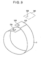
- the injection port forming device 15 forms a tab 3A by punching a part of the tape 3, which is to be wound around the peripheral surfaces of the first molding die 1 and the second molding die 2, in a substantially C shape.
- the injection port forming device 15 includes a pair of press dies 151 and 152 oppositely positioned with an intermediation of the tape 3.
- the press die 151 of the two press dies is a male die having a blade 151 A of a substantially C shape
- the press die 152 of the other one of the two press dies is a female die that receives the blade 151A.
- the injection port forming device 15 is not limited to the press type structure in which the tape 3 is punched to form the tab 3A, and a method is not specified as long as the tab 3A can be formed.
- a cutting method using laser light there may be employed a cutting method using laser light, a method of pressing a heated die against the tape 3 to melt the tape 3, or a method of spraying heat-compressed air.
- the shape of the tab 3A is not limited to the substantially C shape. As long as it is not a complete circle, there may be employed a squared C shape, a V shape, a semicircular arc shape, or the like.
- the tape winding device 16 includes: a rotation driving device (not shown) that drives the spindle 131 holding the first molding die 1 to rotate; another rotation driving device (not shown) that drives the spindle 132 holding the second molding die 2 to rotate; and a guide roller 160 that presses the tape 3 against the peripheral surfaces of the first molding die 1 and the second molding die 2 in order to wind the tape 3 around the peripheral surfaces of the first molding die 1 and the second molding die 2.
- a rotation driving device (not shown) that drives the spindle 131 holding the first molding die 1 to rotate
- another rotation driving device (not shown) that drives the spindle 132 holding the second molding die 2 to rotate
- a guide roller 160 that presses the tape 3 against the peripheral surfaces of the first molding die 1 and the second molding die 2 in order to wind the tape 3 around the peripheral surfaces of the first molding die 1 and the second molding die 2.
- an adhesive is applied in advance.
- the tape 3 is wound around the entire peripheral surfaces of the first molding die 1 and the second molding die 2.
- a predetermined position of the tape 3 is cut by a cutter (not shown) to form the mold 4.
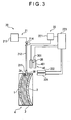
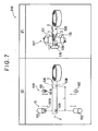
- FIG. 3 shows the configuration of the plastic lens manufacturing apparatus except for the mold forming apparatus 10.
- the plastic lens manufacturing apparatus includes: a resin injection device 20 that injects a resin material for forming a plastic lens from the injection port 3B which is formed by depressing the tab 3A into the mold 4; a tab restoring device 30 that restores the tab 3A to its original position; and an injection port sealing device 40 that seals the injection port 3B.
- the resin injection device 20 includes: a placing unit (not shown) that places the mold 4 so that an axial direction thereof becomes substantially horizontal; a supplying unit 21 that supplies the resin material to the inner portion of the mold 4; and a control unit 22 that controls an amount of the resin material to be supplied.
- the supplying unit 21 includes: a nozzle 211 that injects the resin material into the mold 4 from the injection port 3B; a resin material flow tube 212 whose lower end portion is connected to a base end portion of the nozzle 211; and a material storing unit 213 that is connected to an upper end portion of the resin material flow tube 212.
- the resin material flow tube 212 is provided with an injection control valve 214.
- the injection control valve 214 controls an opening amount of the resin material flow tube 212, thereby controlling an amount of the resin material to be supplied from the nozzle 211.
- the nozzle 211 is arranged so that an end thereof opposes the tab 3A formed in the tape 3 of the mold 4. Further, the nozzle 211 is configured so as to wedge the tab 3A into the mold 4 by an advancing and retreating device (not shown) and to detach from the tab 3A.
- the control unit 22 includes: a flow rate regulating unit 221 that controls the injection control valve 214; a sensor 222 that detects that the resin material has been injected up to a predetermined position of the inner portion of the mold 4; a sensor 224 that switches a flow of the resin material; and a control unit main body 223 that controls the flow rate regulating unit 221 in response to signals from the sensors 222 and 224.
- Each of the sensors 222 and 224 arranged in the vicinity of the injection port 3B of the mold 4 is an optical sensor that detects the amount of the resin material to be injected into the mold 4 using light.
- the tab restoring device 30 restores the tab 3A depressed by the nozzle 211 to its original position, and includes a suction pipe 301 that sucks the tab 3A and a vacuum suction device (not shown) connected to a base end portion of the suction pipe 301.
- the vacuum suction device is controlled by the control unit main body 223.
- the suction pipe 301 is capable of moving three-dimensionally. In a case where the resin injection device 20 or the injection port sealing device 40 is operated, the suction pipe 301 retreats to a position where the suction pipe 301 can avoid interference with the resin injection device 20 or the injection port sealing device 40. In a case where the tab restoring device 30 is operated, the suction pipe 301 moves to the vicinity of the tab 3A.
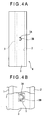
- the injection port sealing device 40 seals a circumferential portion of the tab 3A restored to the original position, and includes a sealing resin supplying device (not shown) that supplies an ultraviolet-curable resin 5 (see FIG. 4B ) to the circumferential portion of the tab 3A and an ultraviolet ray supplying device 401 that supplies ultraviolet rays to the ultraviolet-curable resin 5 covering an upper surface of the tab 3A.
- the ultraviolet ray supplying device 401 is controlled by the control unit main body 223.
- the first molding die 1 is chucked by the first centripetal device 11 A and the second molding die 2 is chucked by the second centripetal device 11B, whereby each molding die is centripetally positioned and the outer diameter is measured.
- the spindles 131 and 132 respectively absorbs and holds the first molding die 1 and the second molding die 2 by the first measuring device 13A and the second measuring device 13B, and the first measuring device 13A and the second measuring device 13B respectively measure the thickness of the first molding die 1 between the surface center position absorbed by the spindle 131 and the bottom surface center position thereof and the thickness of the second molding die 2 between the surface center position absorbed by the spindle 132 and the top surface center position thereof.
- the molding die positioning device 14 positions each of the spindles 131 and 132 in a spacing direction, using data on the thickness of the first molding die 1 between the surface center position absorbed by the spindle 131 and the bottom surface center position thereof, the thickness of the second molding die 2 between the surface center position absorbed by the spindle 132 and the top surface center position thereof, and center thickness, to allow the center position of the first molding die 1 and the center position of the second molding die 2 to be apart from each other by a predetermined distance (center thickness).
- the molding die positioning device 14 positions each of the spindles 131 and 132 in a rotating direction so that an injecting position is at a position where a value of a portion corresponding to the thickness of the peripheral portion of a lens becomes a maximum value in order to facilitate an insertion of the nozzle 211 when the resin material for forming a plastic lens is injected into the mold 4.
- a position of each of the spindles 131 and 132 where a value of a portion corresponding to the thickness of the peripheral portion of a lens becomes a maximum value is decided based on the astigmatic axis direction of the second molding die 2 measured by using the mold astigmatic axis detecting device 12.
- a value of a portion corresponding to a thickness of a peripheral portion of the second molding die 2 and a portion corresponding to the thickness of the peripheral portion of a plastic lens at the injecting position is measured. Based on the value of the portion corresponding to the thickness of the peripheral portion of the second molding die 2 and the value of the portion corresponding to the thickness of the peripheral portion of a plastic lens, an injection port position in a thickness direction of the peripheral portion of the first molding die 1 and the second molding die 2 with the lower surface of the second molding die 2 as a reference is calculated. Then, based on the outer diameter of each of the first molding die 1 and the second molding die 2, outer peripheral values thereof are calculated.
- the injection port forming device 15 performs an injection port forming step in which the part of the tape 3 is cut out non-circularly, whereby the tab 3A is formed.
- the position at which the tab 3A is to be formed on the tape 3 in a height direction (the position in a width direction of the tape 3) is decided based on the calculated value of the injection port position with the lower surface of the second molding die 2 which is obtained in the previous step as a reference.
- the position in a lateral direction (the position in a longitudinal direction of the tape 3) is decided by controlling a tape winding start position so that the tab 3A comes to the position at which a value of a portion corresponding to the thickness of the peripheral portion of the positioned plastic lens becomes a maximum value.
- the tape winding device 16 winds the tape 3 on which the tab 3A has been formed around the peripheral surfaces of the first molding die 1 and the second molding die 2.
- the first molding die 1 and the second molding die 2 are synchronously rotated by the spindles 131 and 132, whereby the tape 3 is wound around the peripheral surfaces of the first molding die 1 and the second molding die 2.
- the height of the lower surface of the second molding die 2 is the same as the height of the lower edge of the tape 3 (see FIG. 4A ).
- the tape 3 When the tape 3 is wound around the entire peripheral surfaces of the first molding die 1 and the second molding die 2 and a portion of the tape 3 overlaps another portion thereof, the tape 3 is cut. As a result, the mold 4 is structured.
- the resin injection device 20 injects the resin material for forming a plastic lens into the mold 4.
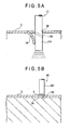
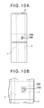
- the mold 4 is positioned so that the tab 3A is at the highest position. After that, the nozzle 211 is lowered and the tab 3A is depressed with the lower end portion thereof (see FIG. 5A ). The tab 3A is deformed in a curved manner due to the elastic force thereof. Since the tab 3A is deformed, the bent portion and the vacant portion formed through depressing of the tab 3A, form the injection port 3B having an annular shape on the tape 3.
- the resin material for forming a plastic lens is injected into the mold 4 from the injection port 3B via the nozzle 211.
- the control unit 22 initiates and terminates the injection and switches the injection flow.
- the sensor 224 detects that the fluid level of the resin material for forming a plastic lens has reached the vicinity of the injection port 3B, and the injection flow is gradually decreased.
- the signal is transmitted from the sensor 222 to the control unit 22, thereby stopping the injection of the resin material for forming a plastic lens.
- the nozzle 211 When a predetermined amount of the resin material is injected into the mold 4, the nozzle 211 is ascended. As a result, the tab 3A depressed by the lower end portion of the nozzle 211 returns to a position close to the original position due to the elastic force thereof and the ascendant level of the resin material (see the imaginary line of FIG. 5A ).
- the tab restoring device 30 is operated.
- the suction pipe 301 is moved to the vicinity of the tab 3A, the tab 3A is sucked by the suction pipe 301 by operating the vacuum suction device, and the injection port 3B is sealed.
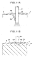
- the injection port sealing device 40 is operated to thereby seal the injection port 3B.
- the ultraviolet-curable resin 5 is applied only to the tab 3A of the tape 3 (see FIG. 5B ) and the ultraviolet ray supplying device 401 irradiates ultraviolet rays onto the ultraviolet-curable resin 5, thereby curing the ultraviolet-curable resin 5.
- FIGS. 5A and 5B in order to indicate a configuration of the tab 3A clearly, a lateral surface of the cut out portion forming the tab 3A is illustrated in a wide manner.
- the mold 4 is placed in a furnace to be heated and cured.
- the mold 4 is taken out of the furnace, the tape 3 wound around the mold 4 is peeled off, and the first molding die 1 and the second molding die 2 are removed, whereby the base material of a plastic lens is formed.
- the surface of the base material is polished, processed, etc. if required, whereby a plastic lens is obtained.
- the first exemplary embodiment can obtain the following effects.
- the invention is not limited to the above second exemplary embodiment.
- the invention can be modified, improved, or the like as long as the object of the invention is attained.
- each of the tabs 3A and 53A may be processed after the tape 3 is wound around the peripheral surfaces of the first molding die 1 and the second molding die 2.
- a member other than the nozzle 211 may be newly provided and the member may wedge each of the tabs 3A and 53A.
- each of the plurality of tabs 3A and the plurality of tabs 53A may be arranged close to each other in the longitudinal direction of the tape 3 and the resin may be injected into the mold 4 by inserting the nozzle 221 in each of the plurality of tabs 3A and the plurality of tabs 53A.
- the tab 53A may be formed. In this case, by depressing the tabs 53A overlapping one another by a single nozzle 211, the lower end portion of the nozzle 211 may be inserted into the inner portion of the mold 4.
- the invention can be applied to a device in which a plastic lens for glasses, a telescope, a lens for a camera, or the like is manufactured.
Landscapes
- Engineering & Computer Science (AREA)
- Mechanical Engineering (AREA)
- Manufacturing & Machinery (AREA)
- Health & Medical Sciences (AREA)
- Ophthalmology & Optometry (AREA)
- Casting Or Compression Moulding Of Plastics Or The Like (AREA)
- Moulds For Moulding Plastics Or The Like (AREA)
Claims (7)
- Verfahren zum Ausbilden einer Hohlform (4) umfassend:Wickeln eines Bands (3) um Umfangsoberflächen eines ersten Hohlformwerkzeugs (1) und eines zweiten Hohlformwerkzeugs (2), um eine Hohlform (4) zusammenzubauen, undAusbilden einer Einspeisöffnung an dem Band (3) zum Einspeisen eines Harzmaterials zum Ausbilden einer Kunststofflinse in die Hohlform (4),
dadurch gekennzeichnet, dassein Lappen (53A) durch nicht-kreisförmiges Herausschneiden eines Teils des Bands (3) ausgebildet wird,das Wickeln an dem Band (3) um Umfangsoberflächen des ersten Hohlformwerkzeugs (1) und des zweiten Hohlformwerkzeugs (2) nach dem Ausbilden des Lappens (53A) durchgeführt wird,die Einspeisöffnung einen Einspeisöffnungshauptkörper (53B) und den Lappen (53A) zum Abdichten des Einspeisöffnungshauptkörpers (53B) beinhaltet,das Ausbilden des Lappens beinhaltet, den Lappen (53A) zum Abdichten des vorab ausgebildeten Einspeisöffnungshauptkörpers (53B) auszubilden und einen vorab ausgebildeten bandartigen Einspeisöffnungsausbildungsabschnitt (53C), der den Einspeisöffnungshauptkörper (53B) aufweist, auf den Lappen (53A) zu überlagern,das Überlagern des Bands beinhaltet, den Einspeisöffnungshauptkörper (53B), der so ausgebildet ist, dass er eine Fläche aufweist, die kleiner als die Fläche des Lappens (53A) ist, so anzuordnen, dass der Einspeisöffnungshauptkörper (53B) oberhalb des Lappens (53A) angeordnet ist, unddas Wickeln des Bands beinhaltet, das Band (3) so um die Umfangsoberflächen des ersten Hohlformwerkzeugs (1) und des zweiten Hohlformwerkzeugs (2) zu wickeln, dass beide Endabschnitte des Bands (3) aufeinander überlagert sind und der Lappen (53A) freigelegt ist. - Verfahren zum Ausbilden einer Hohlform (4) nach Anspruch 1, bei demder Einspeisöffnungsausbildungsabschnitt (53C) mit dem Endabschnitt des Bands (3) zusammenhängend ausgebildet ist, unddas Ausbilden des Einspeisöffnungshauptkörpers und das Ausbilden des Lappens im Wesentlichen zum gleichen Zeitpunkt durchgeführt werden.
- Verfahren zum Ausbilden einer Kunststofflinse umfassend:Formen der Hohlform (4) durch Verwenden des Verfahrens zum Ausbilden einer Hohlform (4) nach Anspruch 1 oder 2,nachfolgendes Herunterdrücken des Lappens (53A) durch eine Düse (211) und Einspeisen des Harzmaterials zum Ausbilden der Kunststofflinse aus der Düse (211) von der Einspeisöffnung in die Hohlform (4) undZurückziehen und Zurücksetzen des durch die Düse (211) heruntergedrückten Lappens (53A) in dessen ursprüngliche Stellung nach dem Einspeisen des Harzes,wobei das Zurückziehen durch Ansaugen des Lappens (53A) durchgeführt wird.
- Verfahren zum Ausbilden einer Kunststofflinse nach Anspruch 3, das ferner ein Abdichten der Einspeisöffnung (53B) nach dem Einspeisen des Harzes umfasst.
- Hohlformausbildevorrichtung (510) umfassendeine Einrichtung zum Wickeln eines Bands (3) um Umfangsoberflächen eines ersten Hohlformwerkzeugs (1) und eines zweiten Hohlformwerkzeugs (2),
gekennzeichnet durcheine Einrichtung zum Ausbilden eines Lappens (53A) an dem Band (3) zum Einspeisen eines Harzmaterials zum Ausbilden einer Kunststofflinse,wobei die Lappenausbildeeinrichtung den Lappen (53A) durch nicht-kreisförmiges Herausschneiden eines Teils des Lappens (53A) ausbildet,eine Einrichtung (15) zum Ausbilden eines Einspeisöffnungshauptkörpers (53B) an einem anderen Ende des Bands (3), der eine Fläche aufweist, die kleiner als die Fläche des Lappens (53A) ist, undeine Bandwickeleinrichtung (16; 516) zum Überlagern beider Endabschnitte des Bands (3), so dass der Einspeisöffnungshauptkörper (53B) oberhalb des Lappens (53A) angeordnet ist, und zum Wickeln des Bands (3) um die Umfangsoberflächen des ersten Hohlformwerkzeugs (1) und des zweiten Hohlformwerkzeugs (2). - Herstellvorrichtung für eine Kunststofflinse umfassend:die Hohlformausbildevorrichtung (510) nach Anspruch 5,eine Harzeinspeiseinrichtung mit einer Düse (211) zum Herunterdrücken des Lappens (53A), wobei die Einrichtung das Harzmaterial zum Ausbilden der Kunststofflinse durch die Düse (211) aus einer Einspeisöffnung (53B) in eine Hohlform (4) einspeist, undeine Einrichtung zum Zurückziehen und Zurücksetzen des durch die Düse (211) heruntergedrückten Lappens (53A) in dessen ursprüngliche Stellung durch Ansaugen des Lappens (53A).
- Herstellvorrichtung für eine Kunststofflinse nach Anspruch 6, ferner umfassend eine Einrichtung (40) zum Abdichten der Einspeisöffnung (53B).
Applications Claiming Priority (3)
| Application Number | Priority Date | Filing Date | Title |
|---|---|---|---|
| JP2006012051 | 2006-01-20 | ||
| JP2006012052 | 2006-01-20 | ||
| JP2006304323A JP4957196B2 (ja) | 2006-01-20 | 2006-11-09 | 成型用モールドの成形方法及びその成形装置、プラスチックレンズの製造方法及びその製造装置 |
Publications (3)
| Publication Number | Publication Date |
|---|---|
| EP1810817A2 EP1810817A2 (de) | 2007-07-25 |
| EP1810817A3 EP1810817A3 (de) | 2008-06-25 |
| EP1810817B1 true EP1810817B1 (de) | 2009-11-11 |
Family
ID=37963585
Family Applications (1)
| Application Number | Title | Priority Date | Filing Date |
|---|---|---|---|
| EP07001026A Expired - Fee Related EP1810817B1 (de) | 2006-01-20 | 2007-01-18 | Verfahren und Vorrichtung zur Herstellung einer Form sowie Verfahren und Vorrichtung zur Herstellung von Kunststofflinsen |
Country Status (5)
| Country | Link |
|---|---|
| US (1) | US8262951B2 (de) |
| EP (1) | EP1810817B1 (de) |
| JP (1) | JP4957196B2 (de) |
| KR (1) | KR100854188B1 (de) |
| DE (1) | DE602007003108D1 (de) |
Cited By (1)
| Publication number | Priority date | Publication date | Assignee | Title |
|---|---|---|---|---|
| CN109605694A (zh) * | 2018-12-21 | 2019-04-12 | 丹阳市雷登智能科技有限公司 | 镜片模具的合模方法以及检测装置和合模机 |
Families Citing this family (12)
| Publication number | Priority date | Publication date | Assignee | Title |
|---|---|---|---|---|
| JP4827181B2 (ja) * | 2006-08-29 | 2011-11-30 | オリンパス株式会社 | 撮像装置 |
| WO2010114023A1 (ja) * | 2009-03-31 | 2010-10-07 | Hoya株式会社 | 累進屈折力眼鏡レンズの製造方法 |
| JP2010240866A (ja) * | 2009-04-01 | 2010-10-28 | Seiko Epson Corp | プラスチックレンズ成形装置 |
| JP5430334B2 (ja) * | 2009-10-05 | 2014-02-26 | Hoya株式会社 | 成形型及びプラスチックレンズの製造方法 |
| JP5717363B2 (ja) * | 2010-06-23 | 2015-05-13 | Hoya株式会社 | プラスチックレンズ成形用成形型およびプラスチックレンズの製造方法 |
| TW201313458A (zh) * | 2011-09-29 | 2013-04-01 | Hon Hai Prec Ind Co Ltd | 模仁加工方法 |
| KR101383132B1 (ko) * | 2012-08-17 | 2014-04-08 | 한국기초과학지원연구원 | 안경 렌즈용 모노머 자동 주입장비 및 이를 이용한 안경렌즈 생산방법 |
| KR101597099B1 (ko) * | 2015-10-21 | 2016-02-24 | 최재권 | 시력검사용 렌즈 성형방법 |
| KR102166475B1 (ko) * | 2017-12-14 | 2020-10-16 | 주식회사 엘지화학 | 배터리 모듈의 제조 방법 |
| KR102133094B1 (ko) * | 2018-10-29 | 2020-07-10 | 주식회사 케이오씨솔루션 | 광학재료용 모노머의 몰드 자동 주입방법 |
| FR3097141B1 (fr) * | 2019-06-12 | 2021-05-14 | Secam | Dispositif de remplissage d’une substance durcissable dans un insert assemblé dans un trou d’un panneau sandwich |
| CN115157506B (zh) * | 2021-02-04 | 2023-11-28 | 浙江大学台州研究院 | 一种精准检测以及控制液位的镜片浇注方法 |
Family Cites Families (17)
| Publication number | Priority date | Publication date | Assignee | Title |
|---|---|---|---|---|
| GB2236273B (en) * | 1989-09-27 | 1992-09-30 | Shinko Sellbic Co Ltd | Stringiness-preventing pad used in an injection mould |
| FR2672540B1 (fr) * | 1991-02-08 | 1994-12-09 | Itw De France | Bouchon pour une ouverture circulaire pratiquee dans une tole, et procede de fabrication de panneaux sandwichs utilisant ce bouchon. |
| JP3345925B2 (ja) * | 1992-11-20 | 2002-11-18 | セイコーエプソン株式会社 | プラスチック硬化物の製造方法 |
| JPH07164550A (ja) * | 1993-12-15 | 1995-06-27 | Nikon Corp | 眼鏡用プラスチックレンズの製造方法 |
| FR2718075B1 (fr) * | 1994-03-29 | 1996-06-07 | Essilor Int | Procédé pour la constitution d'un moule propre à l'obtention d'une lentille optique, moule correspondant et lentille optique obtenue. |
| JP3646743B2 (ja) * | 1995-09-25 | 2005-05-11 | セイコーエプソン株式会社 | プラスチックレンズ原料液の注入方法 |
| JPH09300478A (ja) * | 1996-05-16 | 1997-11-25 | Nikon Corp | 光学素子の成形方法、成形用ガスケット、光学素子の成形に用いる注入機 |
| JP3800711B2 (ja) * | 1996-07-25 | 2006-07-26 | セイコーエプソン株式会社 | プラスチックレンズの製造方法 |
| JP2000108217A (ja) * | 1998-10-02 | 2000-04-18 | Seiko Epson Corp | プラスチックレンズの製造方法 |
| JP2001277262A (ja) * | 2000-04-04 | 2001-10-09 | Seiko Epson Corp | 注型成形用キャビティの封止方法およびこれを用いたプラスチックレンズの製造方法 |
| JP2002240053A (ja) | 2001-02-21 | 2002-08-28 | Seiko Epson Corp | プラスチック製品の注型成形方法及び装置 |
| US6416689B1 (en) * | 2001-03-21 | 2002-07-09 | Essilor International Compagnie General D'optique | Method for molding plastic lenses |
| JP2003231134A (ja) * | 2002-02-08 | 2003-08-19 | Seiko Epson Corp | 眼鏡用プラスチックレンズの注型重合方法 |
| JP2003231135A (ja) * | 2002-02-08 | 2003-08-19 | Seiko Epson Corp | 眼鏡用プラスチックレンズの注型重合方法 |
| US6843940B2 (en) * | 2002-08-05 | 2005-01-18 | Essilor International Compagnie Generale D'optique | Method and mold for molding plastic lenses |
| JP4214870B2 (ja) * | 2003-09-10 | 2009-01-28 | セイコーエプソン株式会社 | 光学物品の製造方法 |
| KR20070087715A (ko) * | 2005-07-06 | 2007-08-29 | 민병직 | 탭핑된 몰드의 폴리머 주입 방법 및 몰드용 테이프 |
-
2006
- 2006-11-09 JP JP2006304323A patent/JP4957196B2/ja not_active Expired - Fee Related
-
2007
- 2007-01-18 EP EP07001026A patent/EP1810817B1/de not_active Expired - Fee Related
- 2007-01-18 KR KR1020070005578A patent/KR100854188B1/ko not_active IP Right Cessation
- 2007-01-18 DE DE602007003108T patent/DE602007003108D1/de active Active
- 2007-01-22 US US11/655,922 patent/US8262951B2/en not_active Expired - Fee Related
Cited By (2)
| Publication number | Priority date | Publication date | Assignee | Title |
|---|---|---|---|---|
| CN109605694A (zh) * | 2018-12-21 | 2019-04-12 | 丹阳市雷登智能科技有限公司 | 镜片模具的合模方法以及检测装置和合模机 |
| CN109605694B (zh) * | 2018-12-21 | 2020-10-30 | 丹阳市雷登智能科技有限公司 | 镜片模具的合模方法以及检测装置和合模机 |
Also Published As
| Publication number | Publication date |
|---|---|
| DE602007003108D1 (de) | 2009-12-24 |
| US8262951B2 (en) | 2012-09-11 |
| JP2007216665A (ja) | 2007-08-30 |
| KR100854188B1 (ko) | 2008-08-26 |
| EP1810817A2 (de) | 2007-07-25 |
| EP1810817A3 (de) | 2008-06-25 |
| JP4957196B2 (ja) | 2012-06-20 |
| KR20070077088A (ko) | 2007-07-25 |
| US20070170557A1 (en) | 2007-07-26 |
Similar Documents
| Publication | Publication Date | Title |
|---|---|---|
| EP1810817B1 (de) | Verfahren und Vorrichtung zur Herstellung einer Form sowie Verfahren und Vorrichtung zur Herstellung von Kunststofflinsen | |
| CN101404241B (zh) | 保护带剥离方法及采用该保护带剥离方法的装置 | |
| JP2006192710A (ja) | 溶融樹脂押出積層造形方法およびその装置 | |
| CS235013B2 (en) | Tube covering tank, method of its production and equipment for application of this method | |
| CN107891224B (zh) | 接合结构体及该接合结构体的制造方法 | |
| JP2007245515A (ja) | プラスチックレンズの製造方法及びその製造装置 | |
| US6347655B1 (en) | Die bonding device and semiconductor device | |
| US11077614B2 (en) | Ledge forming system for producing a conjunct nozzle | |
| EP2065168A1 (de) | Verfahren und vorrichtung zur herstellung eines schlauchs mit darin befindlichem rohr | |
| US11203165B2 (en) | Methods and apparatus for embedding a wire intermittently | |
| KR101977150B1 (ko) | 자동차 부품용 맞춤형 고무호스의 제조방법 및 이에 제조된 자동차 부품용 맞춤형 고무호스 | |
| CN107876977B (zh) | 接合结构体及该接合结构体的制造方法 | |
| KR101677949B1 (ko) | 자동차용 고무호스의 테이핑 자동 가압장치 | |
| JP4280328B2 (ja) | 留置針組立体および内針の製造方法 | |
| JP2006240042A (ja) | プラスチックレンズの製造方法及びその製造装置 | |
| JP2010067782A (ja) | 表面保護フィルム剥離装置 | |
| CN106017233A (zh) | 一种单刀剥离导爆索的进刀曲线控制技术 | |
| KR100915647B1 (ko) | 초음파 천공 장치 및 이를 이용한 범퍼 페시어 천공 방법 | |
| KR100650093B1 (ko) | 다층 기록 매체의 형성 방법 및 장치 및 다층 기록 매체 | |
| JP2008296985A (ja) | 接着剤類収容パウチおよびその製造法 | |
| JP3785725B2 (ja) | プラスチックレンズの製造方法及び製造装置 | |
| US20230415434A1 (en) | Retractable mold built-in precision pins to locate components during layup process for fabrication of wind turbine blades | |
| CN100544927C (zh) | 成型用模具的成形方法及其成形装置、塑料透镜的制造方法及其制造装置 | |
| JPH08142100A (ja) | 中空樹脂成形品の製造方法及びそのためのガス注入孔封止装置 | |
| CN108136686A (zh) | 塑料焊接方法和设备 |
Legal Events
| Date | Code | Title | Description |
|---|---|---|---|
| PUAI | Public reference made under article 153(3) epc to a published international application that has entered the european phase |
Free format text: ORIGINAL CODE: 0009012 |
|
| AK | Designated contracting states |
Kind code of ref document: A2 Designated state(s): AT BE BG CH CY CZ DE DK EE ES FI FR GB GR HU IE IS IT LI LT LU LV MC NL PL PT RO SE SI SK TR |
|
| AX | Request for extension of the european patent |
Extension state: AL BA HR MK YU |
|
| PUAL | Search report despatched |
Free format text: ORIGINAL CODE: 0009013 |
|
| AK | Designated contracting states |
Kind code of ref document: A3 Designated state(s): AT BE BG CH CY CZ DE DK EE ES FI FR GB GR HU IE IS IT LI LT LU LV MC NL PL PT RO SE SI SK TR |
|
| AX | Request for extension of the european patent |
Extension state: AL BA HR MK RS |
|
| 17P | Request for examination filed |
Effective date: 20081107 |
|
| AKX | Designation fees paid |
Designated state(s): DE FR GB |
|
| GRAP | Despatch of communication of intention to grant a patent |
Free format text: ORIGINAL CODE: EPIDOSNIGR1 |
|
| GRAS | Grant fee paid |
Free format text: ORIGINAL CODE: EPIDOSNIGR3 |
|
| GRAA | (expected) grant |
Free format text: ORIGINAL CODE: 0009210 |
|
| AK | Designated contracting states |
Kind code of ref document: B1 Designated state(s): DE FR GB |
|
| REG | Reference to a national code |
Ref country code: GB Ref legal event code: FG4D |
|
| REF | Corresponds to: |
Ref document number: 602007003108 Country of ref document: DE Date of ref document: 20091224 Kind code of ref document: P |
|
| PLBE | No opposition filed within time limit |
Free format text: ORIGINAL CODE: 0009261 |
|
| STAA | Information on the status of an ep patent application or granted ep patent |
Free format text: STATUS: NO OPPOSITION FILED WITHIN TIME LIMIT |
|
| 26N | No opposition filed |
Effective date: 20100812 |
|
| REG | Reference to a national code |
Ref country code: DE Ref legal event code: R082 Ref document number: 602007003108 Country of ref document: DE Representative=s name: HOFFMANN - EITLE, DE |
|
| REG | Reference to a national code |
Ref country code: DE Ref legal event code: R082 Ref document number: 602007003108 Country of ref document: DE Representative=s name: HOFFMANN - EITLE, DE Effective date: 20130807 Ref country code: DE Ref legal event code: R082 Ref document number: 602007003108 Country of ref document: DE Representative=s name: HOFFMANN - EITLE PATENT- UND RECHTSANWAELTE PA, DE Effective date: 20130807 Ref country code: DE Ref legal event code: R081 Ref document number: 602007003108 Country of ref document: DE Owner name: HOYA LENS MANUFACTURING PHILIPPINES INC., PH Free format text: FORMER OWNER: SEIKO EPSON CORP., TOKYO, JP Effective date: 20130807 |
|
| REG | Reference to a national code |
Ref country code: FR Ref legal event code: TP Owner name: HOYA LENS MANUFACTURING PHILIPPINES INC., PH Effective date: 20131003 |
|
| REG | Reference to a national code |
Ref country code: GB Ref legal event code: 732E Free format text: REGISTERED BETWEEN 20140220 AND 20140226 |
|
| REG | Reference to a national code |
Ref country code: FR Ref legal event code: PLFP Year of fee payment: 9 |
|
| PGFP | Annual fee paid to national office [announced via postgrant information from national office to epo] |
Ref country code: DE Payment date: 20150113 Year of fee payment: 9 |
|
| PGFP | Annual fee paid to national office [announced via postgrant information from national office to epo] |
Ref country code: FR Payment date: 20150108 Year of fee payment: 9 Ref country code: GB Payment date: 20150114 Year of fee payment: 9 |
|
| REG | Reference to a national code |
Ref country code: DE Ref legal event code: R119 Ref document number: 602007003108 Country of ref document: DE |
|
| GBPC | Gb: european patent ceased through non-payment of renewal fee |
Effective date: 20160118 |
|
| REG | Reference to a national code |
Ref country code: FR Ref legal event code: ST Effective date: 20160930 |
|
| PG25 | Lapsed in a contracting state [announced via postgrant information from national office to epo] |
Ref country code: DE Free format text: LAPSE BECAUSE OF NON-PAYMENT OF DUE FEES Effective date: 20160802 Ref country code: GB Free format text: LAPSE BECAUSE OF NON-PAYMENT OF DUE FEES Effective date: 20160118 |
|
| PG25 | Lapsed in a contracting state [announced via postgrant information from national office to epo] |
Ref country code: FR Free format text: LAPSE BECAUSE OF NON-PAYMENT OF DUE FEES Effective date: 20160201 |