EP1809489B1 - Radnaben-gelenk-einheit - Google Patents
Radnaben-gelenk-einheit Download PDFInfo
- Publication number
- EP1809489B1 EP1809489B1 EP05796223A EP05796223A EP1809489B1 EP 1809489 B1 EP1809489 B1 EP 1809489B1 EP 05796223 A EP05796223 A EP 05796223A EP 05796223 A EP05796223 A EP 05796223A EP 1809489 B1 EP1809489 B1 EP 1809489B1
- Authority
- EP
- European Patent Office
- Prior art keywords
- bearing
- joint
- wheel hub
- journal
- constant velocity
- Prior art date
- Legal status (The legal status is an assumption and is not a legal conclusion. Google has not performed a legal analysis and makes no representation as to the accuracy of the status listed.)
- Expired - Lifetime
Links
Images


Classifications
-
- F—MECHANICAL ENGINEERING; LIGHTING; HEATING; WEAPONS; BLASTING
- F16—ENGINEERING ELEMENTS AND UNITS; GENERAL MEASURES FOR PRODUCING AND MAINTAINING EFFECTIVE FUNCTIONING OF MACHINES OR INSTALLATIONS; THERMAL INSULATION IN GENERAL
- F16D—COUPLINGS FOR TRANSMITTING ROTATION; CLUTCHES; BRAKES
- F16D3/00—Yielding couplings, i.e. with means permitting movement between the connected parts during the drive
- F16D3/16—Universal joints in which flexibility is produced by means of pivots or sliding or rolling connecting parts
- F16D3/20—Universal joints in which flexibility is produced by means of pivots or sliding or rolling connecting parts one coupling part entering a sleeve of the other coupling part and connected thereto by sliding or rolling members
- F16D3/22—Universal joints in which flexibility is produced by means of pivots or sliding or rolling connecting parts one coupling part entering a sleeve of the other coupling part and connected thereto by sliding or rolling members the rolling members being balls, rollers, or the like, guided in grooves or sockets in both coupling parts
- F16D3/223—Universal joints in which flexibility is produced by means of pivots or sliding or rolling connecting parts one coupling part entering a sleeve of the other coupling part and connected thereto by sliding or rolling members the rolling members being balls, rollers, or the like, guided in grooves or sockets in both coupling parts the rolling members being guided in grooves in both coupling parts
- F16D3/2237—Universal joints in which flexibility is produced by means of pivots or sliding or rolling connecting parts one coupling part entering a sleeve of the other coupling part and connected thereto by sliding or rolling members the rolling members being balls, rollers, or the like, guided in grooves or sockets in both coupling parts the rolling members being guided in grooves in both coupling parts where the grooves are composed of radii and adjoining straight lines, i.e. undercut free [UF] type joints
-
- B—PERFORMING OPERATIONS; TRANSPORTING
- B60—VEHICLES IN GENERAL
- B60B—VEHICLE WHEELS; CASTORS; AXLES FOR WHEELS OR CASTORS; INCREASING WHEEL ADHESION
- B60B27/00—Hubs
-
- B—PERFORMING OPERATIONS; TRANSPORTING
- B60—VEHICLES IN GENERAL
- B60B—VEHICLE WHEELS; CASTORS; AXLES FOR WHEELS OR CASTORS; INCREASING WHEEL ADHESION
- B60B27/00—Hubs
- B60B27/0005—Hubs with ball bearings
-
- B—PERFORMING OPERATIONS; TRANSPORTING
- B60—VEHICLES IN GENERAL
- B60B—VEHICLE WHEELS; CASTORS; AXLES FOR WHEELS OR CASTORS; INCREASING WHEEL ADHESION
- B60B27/00—Hubs
- B60B27/0015—Hubs for driven wheels
- B60B27/0021—Hubs for driven wheels characterised by torque transmission means from drive axle
- B60B27/0026—Hubs for driven wheels characterised by torque transmission means from drive axle of the radial type, e.g. splined key
-
- B—PERFORMING OPERATIONS; TRANSPORTING
- B60—VEHICLES IN GENERAL
- B60B—VEHICLE WHEELS; CASTORS; AXLES FOR WHEELS OR CASTORS; INCREASING WHEEL ADHESION
- B60B27/00—Hubs
- B60B27/0015—Hubs for driven wheels
- B60B27/0036—Hubs for driven wheels comprising homokinetic joints
- B60B27/0042—Hubs for driven wheels comprising homokinetic joints characterised by the fixation of the homokinetic joint to the hub
-
- B—PERFORMING OPERATIONS; TRANSPORTING
- B60—VEHICLES IN GENERAL
- B60B—VEHICLE WHEELS; CASTORS; AXLES FOR WHEELS OR CASTORS; INCREASING WHEEL ADHESION
- B60B27/00—Hubs
- B60B27/0094—Hubs one or more of the bearing races are formed by the hub
-
- F—MECHANICAL ENGINEERING; LIGHTING; HEATING; WEAPONS; BLASTING
- F16—ENGINEERING ELEMENTS AND UNITS; GENERAL MEASURES FOR PRODUCING AND MAINTAINING EFFECTIVE FUNCTIONING OF MACHINES OR INSTALLATIONS; THERMAL INSULATION IN GENERAL
- F16C—SHAFTS; FLEXIBLE SHAFTS; ELEMENTS OR CRANKSHAFT MECHANISMS; ROTARY BODIES OTHER THAN GEARING ELEMENTS; BEARINGS
- F16C19/00—Bearings with rolling contact, for exclusively rotary movement
- F16C19/02—Bearings with rolling contact, for exclusively rotary movement with bearing balls essentially of the same size in one or more circular rows
- F16C19/14—Bearings with rolling contact, for exclusively rotary movement with bearing balls essentially of the same size in one or more circular rows for both radial and axial load
- F16C19/18—Bearings with rolling contact, for exclusively rotary movement with bearing balls essentially of the same size in one or more circular rows for both radial and axial load with two or more rows of balls
- F16C19/181—Bearings with rolling contact, for exclusively rotary movement with bearing balls essentially of the same size in one or more circular rows for both radial and axial load with two or more rows of balls with angular contact
- F16C19/183—Bearings with rolling contact, for exclusively rotary movement with bearing balls essentially of the same size in one or more circular rows for both radial and axial load with two or more rows of balls with angular contact with two rows at opposite angles
- F16C19/184—Bearings with rolling contact, for exclusively rotary movement with bearing balls essentially of the same size in one or more circular rows for both radial and axial load with two or more rows of balls with angular contact with two rows at opposite angles in O-arrangement
- F16C19/186—Bearings with rolling contact, for exclusively rotary movement with bearing balls essentially of the same size in one or more circular rows for both radial and axial load with two or more rows of balls with angular contact with two rows at opposite angles in O-arrangement with three raceways provided integrally on parts other than race rings, e.g. third generation hubs
-
- F—MECHANICAL ENGINEERING; LIGHTING; HEATING; WEAPONS; BLASTING
- F16—ENGINEERING ELEMENTS AND UNITS; GENERAL MEASURES FOR PRODUCING AND MAINTAINING EFFECTIVE FUNCTIONING OF MACHINES OR INSTALLATIONS; THERMAL INSULATION IN GENERAL
- F16C—SHAFTS; FLEXIBLE SHAFTS; ELEMENTS OR CRANKSHAFT MECHANISMS; ROTARY BODIES OTHER THAN GEARING ELEMENTS; BEARINGS
- F16C2326/00—Articles relating to transporting
- F16C2326/01—Parts of vehicles in general
- F16C2326/02—Wheel hubs or castors
-
- F—MECHANICAL ENGINEERING; LIGHTING; HEATING; WEAPONS; BLASTING
- F16—ENGINEERING ELEMENTS AND UNITS; GENERAL MEASURES FOR PRODUCING AND MAINTAINING EFFECTIVE FUNCTIONING OF MACHINES OR INSTALLATIONS; THERMAL INSULATION IN GENERAL
- F16D—COUPLINGS FOR TRANSMITTING ROTATION; CLUTCHES; BRAKES
- F16D3/00—Yielding couplings, i.e. with means permitting movement between the connected parts during the drive
- F16D3/16—Universal joints in which flexibility is produced by means of pivots or sliding or rolling connecting parts
- F16D3/20—Universal joints in which flexibility is produced by means of pivots or sliding or rolling connecting parts one coupling part entering a sleeve of the other coupling part and connected thereto by sliding or rolling members
- F16D3/22—Universal joints in which flexibility is produced by means of pivots or sliding or rolling connecting parts one coupling part entering a sleeve of the other coupling part and connected thereto by sliding or rolling members the rolling members being balls, rollers, or the like, guided in grooves or sockets in both coupling parts
- F16D3/223—Universal joints in which flexibility is produced by means of pivots or sliding or rolling connecting parts one coupling part entering a sleeve of the other coupling part and connected thereto by sliding or rolling members the rolling members being balls, rollers, or the like, guided in grooves or sockets in both coupling parts the rolling members being guided in grooves in both coupling parts
- F16D2003/22326—Attachments to the outer joint member, i.e. attachments to the exterior of the outer joint member or to the shaft of the outer joint member
-
- Y—GENERAL TAGGING OF NEW TECHNOLOGICAL DEVELOPMENTS; GENERAL TAGGING OF CROSS-SECTIONAL TECHNOLOGIES SPANNING OVER SEVERAL SECTIONS OF THE IPC; TECHNICAL SUBJECTS COVERED BY FORMER USPC CROSS-REFERENCE ART COLLECTIONS [XRACs] AND DIGESTS
- Y10—TECHNICAL SUBJECTS COVERED BY FORMER USPC
- Y10S—TECHNICAL SUBJECTS COVERED BY FORMER USPC CROSS-REFERENCE ART COLLECTIONS [XRACs] AND DIGESTS
- Y10S464/00—Rotary shafts, gudgeons, housings, and flexible couplings for rotary shafts
- Y10S464/904—Homokinetic coupling
- Y10S464/906—Torque transmitted via radially spaced balls
Definitions
- the invention relates to a wheel hub constant velocity joint unit in which a wheel hub with a through hole, which carries an internal shaft toothing, is clamped to the outer joint part of a constant velocity joint on which a pin is formed with an outer shaft toothing, wherein inner shaft toothing of the through hole and outer shaft toothing engage the pin, and a double-row wheel bearing is pushed onto the wheel hub, which comprises an inner bearing ring on which an end face of the outer joint part is directly supported.
- a screw which is supported on the outside of the wheel hub and which is screwed into a threaded hole in the journal, serves to tension.
- Such a unit is out of the DE 203 20 496 U1 known, which corresponds to the preambles of claims 1, 7, 9 and 11.
- Arrangements of this type are used on driven, in particular steered wheels of motor vehicles, wherein the wheel and optionally a brake disc are screwed to the flange of the wheel hub, while the constant velocity joint an integral part of a drive shaft (side shaft) forms, consisting of an intermediate shaft, an inner sliding joint and consists of the constant velocity joint mentioned here, which can be designed as a constant velocity joint (front wheel drive) or also as a sliding joint (rear wheel drive).
- the bearing arrangement is to be used in a wheel carrier or steering knuckle.
- the interpretation is to dimension the wheel bearing as small as possible, both for cost reasons with respect to the wheel bearing as well as in terms of the size of the wheel carrier or stub axle.
- the pin diameter is designed on the outer joint part to the required minimum strength, the pin diameter at the same time determines the inner diameter of the wheel hub and thus indirectly, on the strength-related wall thickness of the hub, the inner diameter of the wheel bearing. Due to the elasticity of the pin designed in this way, it comes with torque change, especially in torque surges, which are passed through the assembly to relative movements between the outer joint part and the inner bearing race at the mutual abutment surfaces. This leads to noise and also to fit corrosion.
- a first solution lies in a significantly reduced center distance of joint and bearing in the ratio of given sizes for the bearing width and the joint diameter.
- other solutions are in a qualitatively modified dimensioning of the pin, which is shown much shorter and thicker. This also changes the inner diameter of the wheel hub and thus indirectly the inner diameter and the pitch circle diameter of the wheel bearing.
- Advantageous effects are a substantial increase in the tilting rigidity of the bearing and an increase in the bearing load capacity and thus the bearing life.
- the qualitatively changed dimensioning can be defined by different characteristic size ratios, which differ qualitatively from the previously used size ratios.
- the ratio of bearing width B L and pin diameter at the bearing base D Z is less than 1, ie B L / D Z ⁇ 1.
- Another preferred embodiment provides that the ratio of pin length L Z and pitch circle diameter of the bearing balls is less than 0.5, ie L Z / TKD ⁇ 0.5.
- the ratio of the used tooth length L DEL . and pitch diameter of the bearing balls is less than 0.25, ie L VEZ. / TKD ⁇ 0.25.
- the ratio of pitch circle diameter of the bearing balls and bearing width is greater than 1.9, ie TKD / B L > 1.9.
- another embodiment is characterized in that the cross-sectional area A E of the wheel hub in the region of a separate bearing inner ring and square of the elongation length L DEHN a screw for connecting the hub and outer joint part is greater than 0.2, ie A E / L DEHN 2 >0; 2.
- the rigidity in the strained volume of the wheel hub with the cross section A E can be shown.
- the ratio of center distance A GL between constant velocity universal joint and wheel bearing on the one hand and pin diameter on the journal base D Z on the other hand is less than 2, ie A GL / D Z ⁇ 2 in particular, the ratio of center distance between constant velocity universal joint and wheel bearing on the one hand and pin diameter at the journal base D Z on the other hand less than 1.5, ie A GL / D Z ⁇ 1.5, in particular less than 1.2, ie A GL / D Z ⁇ 1.2.
- a particularly torsionally stiff pin is achieved in the construction in order to minimize the relative movements between the bearing inner ring and hinge stop surface.
- a third solution assumes that the ratio of pitch circle diameter of the wheel bearing TKD and pin length L Z is greater than 2, ie TKD / L Z > 2. It may be preferably provided that the ratio of pitch circle diameter of the wheel bearing TKD and pin length L Z greater Is 2.25, ie TKD / L Z > 2.25, in particular greater than 2.85, ie TKD / L Z > 2.85.
- a torsional stiffness of the wheel bearing is coupled to the rotational stiffness of the pin to minimize the noise generated by the relative movement between the bearing inner ring and the joint stop surface, as well as the influence of the deformations, in particular the wheel hub during operation.
- the ratio of center distance A GL between constant velocity universal joint and wheel bearing on the one hand and pin length L Z on the other hand is greater than 1.95, ie A GL / L Z > 1.95, wherein the ratio in particular greater than 2.0 should be, ie A GL / L Z > 2.0.
- the wheel bearing comprises only a separate bearing inner ring.
- the wheel hub axially opposite to the inner shaft toothing has a diameter reduction of the through hole to further increase the strength of the hub.
- the pin has a central threaded bore into which a screw for clamping the wheel hub is screwed to the outer joint part.
- the joint is a fixed joint, wherein the center of the joint M G is defined axially by the plane of the ball centers with the joint extended.
- the joint is a sliding joint, wherein the center of the joint M G is defined axially by the plane of the ball centers in the extended and set to the center of the axial displacement V S joint.
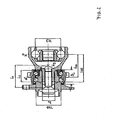
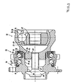
- a wheel hub unit 11 for a drive wheel of a motor vehicle is connected to a constant velocity fixed joint 12 for connection to a drive shaft.
- the wheel hub unit 11 comprises a bearing unit 13 and a wheel hub 30, wherein the bearing unit 13 is mounted on the wheel hub 30 and axially clamped between the wheel hub 30 and constant velocity fixed joint 12.
- the wheel hub 30 includes a flange for screwing a wheel to which a brake disc can be screwed.
- the wheel hub 30 further has a passage opening 29 in which an internal shaft toothing 14 is formed from the side of the joint. At the flange a central substantially radial support surface 15 is formed.
- the constant velocity fixed joint 12 is formed in the manner of a UF joint and includes an outer joint part 16, an inner joint part 17, torque transmitting balls 18 and a ball cage 19. The balls are held and guided in pairs of outer ball tracks 20 in the outer joint part and inner ball tracks 21 in the inner joint part.
- a substantially radial support surface 22 is formed on the hub side.
- a central pin 23 is attached to the outer joint part, which carries an outer shaft toothing 24, which engages in the inner shaft toothing 14 of the hub.
- the pin further has a continuous central threaded bore 25 is formed, into which a screw 27 is screwed, which is supported with its screw head 28 on the radial support surface 15 of the flange 12.
- the double-row bearing 13 comprises a bearing outer ring 31 which can be inserted into a wheel carrier and unspecified outer bearing grooves for two rows of bearing balls 32, 33 is formed.
- a first inner bearing groove for the ball row 32 is formed directly in the wheel hub 30, while a second ball groove for the second ball row 33 is formed in a separate bearing inner ring 34.
- the bearing inner ring 34 projects axially beyond the wheel hub 30, so that the bearing arrangement 13 can be prestressed by the action of the support surface 22 on the outer joint part by means of the screw 27 supported on the support surface 15.
- the arrangement after the FIGS. 1 and 2 is designed to minimize the pitch circle diameter TKD of the wheel bearing.
- the pin 23 is designed for minimum strength and has at a relatively small pin diameter D Z a large journal length L Z.
- D Z the distance between the constructive bearing center M L and the constructive joint means M G increases ; this distance is denoted by A GL .
- L GZ the distance also drawn from the center of the joint to the end of the pin, which is denoted by L GZ and corresponds approximately to A GL + L Z / 2.
- the pitch circle diameter PCD of the joint is drawn.
- the support length L S of the bearing which has a so-called O-configuration, the lines of action of the balls lie on symmetrical conical surfaces which open to each other, and the bearing width B L of the camp.
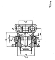
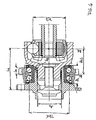
- a wheel hub unit 41 for a drive wheel of a motor vehicle is connected to a fixed constant velocity joint 42 for connection to a drive shaft.
- the wheel hub unit 41 comprises a bearing unit 43 and a wheel hub 60, wherein the bearing unit 43 is mounted on the wheel hub 60 and axially braced between the wheel hub 60 and constant velocity fixed joint 42.
- the wheel hub 60 includes a flange for screwing a wheel to which a brake disc can be screwed.
- the wheel hub 60 further has a passage opening 59 in which an internal shaft toothing 44 is formed from the side of the joint. At the flange a central substantially radial support surface 45 is formed.
- the constant velocity fixed joint 42 is formed in the manner of a UF joint and includes an outer joint part 46, an inner joint part 47, torque transmitting balls 48 and a ball cage 49.
- the balls are held and guided in pairs of outer ball tracks 50 in the outer joint part and inner ball tracks 51 in the inner joint part.
- a substantially radial support surface 52 is formed on the hub side.
- a central pin 53 is attached to the outer joint part, which carries an outer shaft toothing 54, which engages in the inner shaft toothing 44 of the hub.
- a continuous central threaded bore 55 is further formed, into which a screw 57 is screwed, which is supported with its screw head 58 on the radial support surface 45 of the wheel hub 60.
- the support surface 45 is in this case formed on a diameter reduction 56 of the passage opening 59.
- the double-row bearing 43 comprises a bearing outer ring 61 which can be inserted into a wheel carrier and unspecified outer bearing grooves for two rows of bearing balls 62, 63 is formed.
- a first inner bearing groove for the ball row 62 is formed directly in the wheel hub 41, while a second ball groove for the second ball row 63 in a separate bearing inner ring 64 is formed.
- the bearing inner ring 64 projects axially beyond the wheel hub 60, so that the bearing arrangement 43 can be prestressed on the outer joint part 46 under the action of the support surface 52 by means of the screw 57 supported on the support surface 45.
- the inventive arrangement according to the Figures 3 and 4 a short thick and thus torsionally stiff pin.
- the micro-movements occurring so far under varying torque between the support surface on the outer joint part and the corresponding counter surface on the separate bearing inner ring no longer occur in the joint according to the invention.
- a wheel hub unit 71 for a drive wheel of a motor vehicle is connected to a constant velocity sliding joint 72 for connection to a drive shaft, wherein a bearing unit 73 is mounted on the wheel hub unit 71 and axially clamped between the wheel hub unit 71 and the constant velocity sliding joint 72.
- the wheel hub 90 includes a flange for screwing a wheel to which a brake disc can be screwed.
- the wheel hub 90 further has a passage opening 89 in which an inner shaft toothing 74 is formed from the side of the joint forth.
- On the flange is a central in formed substantially radial support surface 75.
- the constant velocity sliding joint 72 is formed like a VL joint and includes an outer joint part 76, an inner joint part 77, torque transmitting balls 78 and a ball cage 79.
- the balls are held and guided in pairs of outer ball tracks 80 in the outer joint part and inner ball tracks 81 in the inner joint part.
- a substantially radial support surface 82 is formed on the hub side.
- a central pin 83 is attached to the outer joint part, which carries an outer shaft toothing 84, which engages in the inner shaft toothing 74 of the hub.
- the pin further has a continuous central threaded bore 85 is formed, into which a screw 87 is screwed, which is supported with its screw head 88 on the radial support surface 75 of the wheel hub 90.
- the support surface 75 is in this case formed on a diameter reduction 86 of the passage opening 89.
- the double-row bearing 73 comprises a bearing outer ring 91 which can be inserted into a wheel carrier and unspecified outer bearing grooves for two rows of bearing balls 92, 93 is formed.
- a first inner bearing groove for the ball row 62 is formed in a bearing inner ring 94, while a second ball groove for the second ball row 63 is formed in a bearing inner ring 95.
- the bearing inner ring 94 is axially over the hub 90, so that the bearing assembly 73 can be biased by the action of the support surface 82 on the outer joint part by means of the supporting surface 75 on the support screw 87.
- the inventive arrangement according to the Figures 5 and 6 a short thick and thus torsionally stiff pin.
- the micro-movements occurring so far under varying torque between the support surface on the outer joint part and the corresponding counter surface on the separate bearing inner ring no longer occur in the joint according to the invention.
Landscapes
- Engineering & Computer Science (AREA)
- Mechanical Engineering (AREA)
- General Engineering & Computer Science (AREA)
- Rolling Contact Bearings (AREA)
- Coupling Device And Connection With Printed Circuit (AREA)
- Auxiliary Devices For And Details Of Packaging Control (AREA)
- Mounting Of Bearings Or Others (AREA)
Applications Claiming Priority (2)
| Application Number | Priority Date | Filing Date | Title |
|---|---|---|---|
| DE102004054907A DE102004054907A1 (de) | 2004-11-12 | 2004-11-12 | Radnaben-Gelenk-Einheit |
| PCT/EP2005/011059 WO2006050785A1 (de) | 2004-11-12 | 2005-10-14 | Radnaben-gelenk-einheit |
Publications (2)
| Publication Number | Publication Date |
|---|---|
| EP1809489A1 EP1809489A1 (de) | 2007-07-25 |
| EP1809489B1 true EP1809489B1 (de) | 2009-04-15 |
Family
ID=35427390
Family Applications (1)
| Application Number | Title | Priority Date | Filing Date |
|---|---|---|---|
| EP05796223A Expired - Lifetime EP1809489B1 (de) | 2004-11-12 | 2005-10-14 | Radnaben-gelenk-einheit |
Country Status (8)
| Country | Link |
|---|---|
| US (1) | US7824272B2 (enExample) |
| EP (1) | EP1809489B1 (enExample) |
| JP (1) | JP4938677B2 (enExample) |
| KR (1) | KR101264073B1 (enExample) |
| CN (1) | CN100554005C (enExample) |
| AT (1) | ATE428579T1 (enExample) |
| DE (2) | DE102004054907A1 (enExample) |
| WO (1) | WO2006050785A1 (enExample) |
Cited By (1)
| Publication number | Priority date | Publication date | Assignee | Title |
|---|---|---|---|---|
| DE102015203413A1 (de) | 2015-02-26 | 2016-09-01 | Schaeffler Technologies AG & Co. KG | Radlageranordnung |
Families Citing this family (19)
| Publication number | Priority date | Publication date | Assignee | Title |
|---|---|---|---|---|
| DE102005054284B4 (de) | 2005-11-11 | 2009-02-05 | Gkn Driveline Deutschland Gmbh | Gleichlaufgelenk-Radnaben-Anordnung mit Hohlanbindung |
| DE102006030682A1 (de) * | 2006-07-04 | 2008-01-17 | Schaeffler Kg | Radnaben-Gelenk-Einheit |
| JP5117128B2 (ja) * | 2007-07-02 | 2013-01-09 | Ntn株式会社 | 車輪用軸受装置 |
| DE102008003646A1 (de) | 2008-01-09 | 2009-07-16 | GM Global Technology Operations, Inc., Detroit | Radnabengelenkeinheit für ein Fahrzeug |
| JP5121526B2 (ja) * | 2008-03-25 | 2013-01-16 | 本田技研工業株式会社 | シャフトドライブ装置 |
| US8616779B2 (en) | 2010-11-29 | 2013-12-31 | Honda Motor Co., Ltd. | Shortened driveshaft stem |
| DE102012008155A1 (de) | 2012-04-24 | 2013-10-24 | Volkswagen Aktiengesellschaft | Gleichlaufgelenk für ein Kraftfahrzeug sowie Anordnung aus einem Gleichlaufgelenk und einer Radnabe |
| DE102012105958A1 (de) * | 2012-07-04 | 2014-01-23 | Thyssenkrupp Steel Europe Ag | Verfahren zur Herstellung eines Verbindungselements zur Übertragung von Drehbewegungen |
| KR101431095B1 (ko) * | 2012-12-24 | 2014-08-21 | 주식회사 일진글로벌 | 구동 휠 베어링장치 |
| KR101532076B1 (ko) * | 2013-08-14 | 2015-06-29 | 주식회사 일진글로벌 | 구동 휠 베어링장치 |
| KR102131856B1 (ko) | 2013-11-04 | 2020-07-08 | 현대모비스 주식회사 | 허브 베어링 |
| KR101599155B1 (ko) * | 2014-12-30 | 2016-03-02 | 현대위아 주식회사 | 등속조인트 |
| CN104802593B (zh) * | 2015-04-16 | 2017-01-25 | 南京航空航天大学 | 轮毂轴承单元 |
| DE102019130321B4 (de) | 2019-11-11 | 2022-04-14 | Audi Ag | Radlagereinheit für ein Kraftfahrzeug sowie Verfahren zum Herstellen einer Radlagereinheit |
| DE102022121486A1 (de) | 2022-08-25 | 2024-03-07 | Audi Aktiengesellschaft | Radlagereinheit für ein Kraftfahrzeug sowie Kraftfahrzeug |
| KR102887849B1 (ko) | 2023-09-05 | 2025-11-18 | 주식회사 일진글로벌 | 자동차용 휠 허브 베어링 유닛 |
| KR20250100343A (ko) | 2023-12-26 | 2025-07-03 | 주식회사 일진글로벌 | 자동차용 휠 허브 베어링 유닛 |
| KR20250100346A (ko) | 2023-12-26 | 2025-07-03 | 주식회사 일진글로벌 | 자동차용 휠 허브 베어링 유닛 |
| KR20250100339A (ko) | 2023-12-26 | 2025-07-03 | 주식회사 일진글로벌 | 개선된 강성 구조를 가지는 자동차용 휠 허브 베어링 유닛 |
Family Cites Families (12)
| Publication number | Priority date | Publication date | Assignee | Title |
|---|---|---|---|---|
| DE3430067C1 (de) * | 1984-08-16 | 1989-04-06 | Löhr & Bromkamp GmbH, 6050 Offenbach | Gelenkwelle |
| DE3536796A1 (de) * | 1985-10-16 | 1987-04-16 | Kugelfischer G Schaefer & Co | Zweireihiges waelzlager, insbesondere fuer raeder von kraftfahrzeugen |
| JPH0375003A (ja) * | 1989-08-17 | 1991-03-29 | Kurata:Kk | 洋服等の皺伸ばし機能を具えた家具 |
| JPH0375003U (enExample) * | 1989-11-27 | 1991-07-29 | ||
| JPH1191307A (ja) * | 1997-09-26 | 1999-04-06 | Ntn Corp | ハブユニット |
| JPH11190346A (ja) * | 1997-12-26 | 1999-07-13 | Ntn Corp | 車輪用軸受ユニット |
| JP2001225605A (ja) * | 2000-02-16 | 2001-08-21 | Nsk Ltd | 自動車用車輪駆動装置 |
| JP3902392B2 (ja) * | 2000-10-10 | 2007-04-04 | Ntn株式会社 | 駆動車輪用軸受装置 |
| JP4613462B2 (ja) * | 2001-08-08 | 2011-01-19 | 株式会社ジェイテクト | 車軸用軸受装置 |
| JP3650746B2 (ja) * | 2001-09-17 | 2005-05-25 | Ntn株式会社 | 車輪用軸受の固定構造及び車輪用軸受 |
| DE10338172B3 (de) | 2003-08-20 | 2005-06-23 | Gkn Driveline Deutschland Gmbh | Radnaben-Drehgelenk-Anordnung |
| DE20320496U1 (de) | 2003-12-16 | 2004-10-07 | Fag Kugelfischer Ag | Nabe |
-
2004
- 2004-11-12 DE DE102004054907A patent/DE102004054907A1/de not_active Withdrawn
-
2005
- 2005-10-14 CN CNB2005800463498A patent/CN100554005C/zh not_active Expired - Lifetime
- 2005-10-14 AT AT05796223T patent/ATE428579T1/de not_active IP Right Cessation
- 2005-10-14 KR KR1020077010766A patent/KR101264073B1/ko not_active Expired - Lifetime
- 2005-10-14 DE DE502005007104T patent/DE502005007104D1/de not_active Expired - Lifetime
- 2005-10-14 WO PCT/EP2005/011059 patent/WO2006050785A1/de not_active Ceased
- 2005-10-14 EP EP05796223A patent/EP1809489B1/de not_active Expired - Lifetime
- 2005-10-14 US US11/667,621 patent/US7824272B2/en active Active
- 2005-10-14 JP JP2007540517A patent/JP4938677B2/ja not_active Expired - Lifetime
Cited By (1)
| Publication number | Priority date | Publication date | Assignee | Title |
|---|---|---|---|---|
| DE102015203413A1 (de) | 2015-02-26 | 2016-09-01 | Schaeffler Technologies AG & Co. KG | Radlageranordnung |
Also Published As
| Publication number | Publication date |
|---|---|
| DE502005007104D1 (de) | 2009-05-28 |
| CN101155700A (zh) | 2008-04-02 |
| JP2008519722A (ja) | 2008-06-12 |
| CN100554005C (zh) | 2009-10-28 |
| EP1809489A1 (de) | 2007-07-25 |
| ATE428579T1 (de) | 2009-05-15 |
| JP4938677B2 (ja) | 2012-05-23 |
| KR20070113189A (ko) | 2007-11-28 |
| US7824272B2 (en) | 2010-11-02 |
| DE102004054907A1 (de) | 2006-09-14 |
| US20080242433A1 (en) | 2008-10-02 |
| WO2006050785A1 (de) | 2006-05-18 |
| KR101264073B1 (ko) | 2013-05-15 |
Similar Documents
| Publication | Publication Date | Title |
|---|---|---|
| EP1809489B1 (de) | Radnaben-gelenk-einheit | |
| DE102005054283B4 (de) | Radnaben-Drehgelenk-Anordnung mit Stirnverzahnung | |
| WO2008003293A2 (de) | Radnaben-gelenk-einheit | |
| DE19843632B4 (de) | Gleichlaufgelenk | |
| EP2142386B1 (de) | Lageranordnung einer über ein drehgelenk antreibbaren radnabe eines kraftfahrzeuges | |
| DE3239121C2 (de) | Lagerungsanordnung einer über ein Gleichlaufdrehgelenk antreibbaren Radnabe | |
| EP1910100B1 (de) | Radlageranordnung mit stirnverzahnung | |
| DE60117098T2 (de) | Vorrichtung für Antriebsrad eines Motorfahrzeuges | |
| DE2329554A1 (de) | Lageranordnung fuer eine antreibbare radnabe eines motorfahrzeugs | |
| DE102004054908B4 (de) | Gelenkaußenteil eines Gleichlaufdrehgelenks für eine Radnaben-Gelenk-Einheit | |
| WO2005028217A1 (de) | Radnaben-drehgelenk-anordnung | |
| WO2005050044A1 (de) | Gelenkaussenteil mit abstützscheibe | |
| DE2626170C3 (de) | Differentialgetriebe mit kombiniert gelagerten Zentralrädern | |
| DE102004055786A1 (de) | Radlagereinheit | |
| DE19842408A1 (de) | Fahrzeuganstriebsstrang | |
| DE102005054285B3 (de) | Radnaben-Drehgelenk-Anordnung mit Stirnverzahnung und Radlagerung | |
| DE2721098A1 (de) | Universalgelenk | |
| EP1912800B1 (de) | Radlagereinheit | |
| EP3819136B1 (de) | Radlagereinheit für ein kraftfahrzeug sowie verfahren zum herstellen einer radlagereinheit | |
| DE102005036660A1 (de) | Radlagereinheit | |
| DE102005052471A1 (de) | Radnabe mit zwischen den Löchern für Radschrauben ausgebildeten axialen Ausnehmungen | |
| DE112022001732T5 (de) | Radlagervorrichtung | |
| DE1836832U (de) | Bremsscheibe, insbesondere fuer schienenfahrzeuge. | |
| DE102018129285A1 (de) | Radlager für ein Kraftfahrzeug | |
| DD224552B1 (de) | Kombinierte anordnung einer vorderen fahrerhauslagerung fuer kippbare fahrerhaeuser |
Legal Events
| Date | Code | Title | Description |
|---|---|---|---|
| PUAI | Public reference made under article 153(3) epc to a published international application that has entered the european phase |
Free format text: ORIGINAL CODE: 0009012 |
|
| 17P | Request for examination filed |
Effective date: 20070418 |
|
| AK | Designated contracting states |
Kind code of ref document: A1 Designated state(s): AT BE BG CH CY CZ DE DK EE ES FI FR GB GR HU IE IS IT LI LT LU LV MC NL PL PT RO SE SI SK TR |
|
| RAP1 | Party data changed (applicant data changed or rights of an application transferred) |
Owner name: GKN DRIVELINE DEUTSCHLAND GMBH Owner name: SCHAEFFLER KG |
|
| DAX | Request for extension of the european patent (deleted) | ||
| GRAP | Despatch of communication of intention to grant a patent |
Free format text: ORIGINAL CODE: EPIDOSNIGR1 |
|
| GRAP | Despatch of communication of intention to grant a patent |
Free format text: ORIGINAL CODE: EPIDOSNIGR1 |
|
| GRAS | Grant fee paid |
Free format text: ORIGINAL CODE: EPIDOSNIGR3 |
|
| GRAA | (expected) grant |
Free format text: ORIGINAL CODE: 0009210 |
|
| AK | Designated contracting states |
Kind code of ref document: B1 Designated state(s): AT BE BG CH CY CZ DE DK EE ES FI FR GB GR HU IE IS IT LI LT LU LV MC NL PL PT RO SE SI SK TR |
|
| REG | Reference to a national code |
Ref country code: CH Ref legal event code: EP Ref country code: GB Ref legal event code: FG4D Free format text: NOT ENGLISH |
|
| REG | Reference to a national code |
Ref country code: IE Ref legal event code: FG4D |
|
| REF | Corresponds to: |
Ref document number: 502005007104 Country of ref document: DE Date of ref document: 20090528 Kind code of ref document: P |
|
| NLV1 | Nl: lapsed or annulled due to failure to fulfill the requirements of art. 29p and 29m of the patents act | ||
| PG25 | Lapsed in a contracting state [announced via postgrant information from national office to epo] |
Ref country code: LT Free format text: LAPSE BECAUSE OF FAILURE TO SUBMIT A TRANSLATION OF THE DESCRIPTION OR TO PAY THE FEE WITHIN THE PRESCRIBED TIME-LIMIT Effective date: 20090415 Ref country code: FI Free format text: LAPSE BECAUSE OF FAILURE TO SUBMIT A TRANSLATION OF THE DESCRIPTION OR TO PAY THE FEE WITHIN THE PRESCRIBED TIME-LIMIT Effective date: 20090415 Ref country code: ES Free format text: LAPSE BECAUSE OF FAILURE TO SUBMIT A TRANSLATION OF THE DESCRIPTION OR TO PAY THE FEE WITHIN THE PRESCRIBED TIME-LIMIT Effective date: 20090726 |
|
| PG25 | Lapsed in a contracting state [announced via postgrant information from national office to epo] |
Ref country code: SE Free format text: LAPSE BECAUSE OF FAILURE TO SUBMIT A TRANSLATION OF THE DESCRIPTION OR TO PAY THE FEE WITHIN THE PRESCRIBED TIME-LIMIT Effective date: 20090715 Ref country code: IS Free format text: LAPSE BECAUSE OF FAILURE TO SUBMIT A TRANSLATION OF THE DESCRIPTION OR TO PAY THE FEE WITHIN THE PRESCRIBED TIME-LIMIT Effective date: 20090815 Ref country code: LV Free format text: LAPSE BECAUSE OF FAILURE TO SUBMIT A TRANSLATION OF THE DESCRIPTION OR TO PAY THE FEE WITHIN THE PRESCRIBED TIME-LIMIT Effective date: 20090415 Ref country code: PL Free format text: LAPSE BECAUSE OF FAILURE TO SUBMIT A TRANSLATION OF THE DESCRIPTION OR TO PAY THE FEE WITHIN THE PRESCRIBED TIME-LIMIT Effective date: 20090415 Ref country code: NL Free format text: LAPSE BECAUSE OF FAILURE TO SUBMIT A TRANSLATION OF THE DESCRIPTION OR TO PAY THE FEE WITHIN THE PRESCRIBED TIME-LIMIT Effective date: 20090415 Ref country code: SI Free format text: LAPSE BECAUSE OF FAILURE TO SUBMIT A TRANSLATION OF THE DESCRIPTION OR TO PAY THE FEE WITHIN THE PRESCRIBED TIME-LIMIT Effective date: 20090415 |
|
| REG | Reference to a national code |
Ref country code: IE Ref legal event code: FD4D |
|
| PG25 | Lapsed in a contracting state [announced via postgrant information from national office to epo] |
Ref country code: RO Free format text: LAPSE BECAUSE OF FAILURE TO SUBMIT A TRANSLATION OF THE DESCRIPTION OR TO PAY THE FEE WITHIN THE PRESCRIBED TIME-LIMIT Effective date: 20090415 Ref country code: IE Free format text: LAPSE BECAUSE OF FAILURE TO SUBMIT A TRANSLATION OF THE DESCRIPTION OR TO PAY THE FEE WITHIN THE PRESCRIBED TIME-LIMIT Effective date: 20090415 Ref country code: DK Free format text: LAPSE BECAUSE OF FAILURE TO SUBMIT A TRANSLATION OF THE DESCRIPTION OR TO PAY THE FEE WITHIN THE PRESCRIBED TIME-LIMIT Effective date: 20090415 Ref country code: CZ Free format text: LAPSE BECAUSE OF FAILURE TO SUBMIT A TRANSLATION OF THE DESCRIPTION OR TO PAY THE FEE WITHIN THE PRESCRIBED TIME-LIMIT Effective date: 20090415 Ref country code: EE Free format text: LAPSE BECAUSE OF FAILURE TO SUBMIT A TRANSLATION OF THE DESCRIPTION OR TO PAY THE FEE WITHIN THE PRESCRIBED TIME-LIMIT Effective date: 20090415 |
|
| PLBE | No opposition filed within time limit |
Free format text: ORIGINAL CODE: 0009261 |
|
| STAA | Information on the status of an ep patent application or granted ep patent |
Free format text: STATUS: NO OPPOSITION FILED WITHIN TIME LIMIT |
|
| PG25 | Lapsed in a contracting state [announced via postgrant information from national office to epo] |
Ref country code: SK Free format text: LAPSE BECAUSE OF FAILURE TO SUBMIT A TRANSLATION OF THE DESCRIPTION OR TO PAY THE FEE WITHIN THE PRESCRIBED TIME-LIMIT Effective date: 20090415 |
|
| 26N | No opposition filed |
Effective date: 20100118 |
|
| PG25 | Lapsed in a contracting state [announced via postgrant information from national office to epo] |
Ref country code: BG Free format text: LAPSE BECAUSE OF FAILURE TO SUBMIT A TRANSLATION OF THE DESCRIPTION OR TO PAY THE FEE WITHIN THE PRESCRIBED TIME-LIMIT Effective date: 20090715 |
|
| BERE | Be: lapsed |
Owner name: SCHAEFFLER K.G. Effective date: 20091031 Owner name: GKN DRIVELINE DEUTSCHLAND G.M.B.H. Effective date: 20091031 |
|
| PG25 | Lapsed in a contracting state [announced via postgrant information from national office to epo] |
Ref country code: MC Free format text: LAPSE BECAUSE OF NON-PAYMENT OF DUE FEES Effective date: 20091031 |
|
| REG | Reference to a national code |
Ref country code: CH Ref legal event code: PL |
|
| PG25 | Lapsed in a contracting state [announced via postgrant information from national office to epo] |
Ref country code: LI Free format text: LAPSE BECAUSE OF NON-PAYMENT OF DUE FEES Effective date: 20091031 Ref country code: BE Free format text: LAPSE BECAUSE OF NON-PAYMENT OF DUE FEES Effective date: 20091031 Ref country code: CH Free format text: LAPSE BECAUSE OF NON-PAYMENT OF DUE FEES Effective date: 20091031 Ref country code: GR Free format text: LAPSE BECAUSE OF FAILURE TO SUBMIT A TRANSLATION OF THE DESCRIPTION OR TO PAY THE FEE WITHIN THE PRESCRIBED TIME-LIMIT Effective date: 20090716 |
|
| PG25 | Lapsed in a contracting state [announced via postgrant information from national office to epo] |
Ref country code: GB Free format text: LAPSE BECAUSE OF NON-PAYMENT OF DUE FEES Effective date: 20091014 |
|
| PG25 | Lapsed in a contracting state [announced via postgrant information from national office to epo] |
Ref country code: AT Free format text: LAPSE BECAUSE OF NON-PAYMENT OF DUE FEES Effective date: 20091014 |
|
| PG25 | Lapsed in a contracting state [announced via postgrant information from national office to epo] |
Ref country code: IT Free format text: LAPSE BECAUSE OF FAILURE TO SUBMIT A TRANSLATION OF THE DESCRIPTION OR TO PAY THE FEE WITHIN THE PRESCRIBED TIME-LIMIT Effective date: 20090415 |
|
| PG25 | Lapsed in a contracting state [announced via postgrant information from national office to epo] |
Ref country code: LU Free format text: LAPSE BECAUSE OF NON-PAYMENT OF DUE FEES Effective date: 20091014 |
|
| PG25 | Lapsed in a contracting state [announced via postgrant information from national office to epo] |
Ref country code: HU Free format text: LAPSE BECAUSE OF FAILURE TO SUBMIT A TRANSLATION OF THE DESCRIPTION OR TO PAY THE FEE WITHIN THE PRESCRIBED TIME-LIMIT Effective date: 20091016 |
|
| PG25 | Lapsed in a contracting state [announced via postgrant information from national office to epo] |
Ref country code: TR Free format text: LAPSE BECAUSE OF FAILURE TO SUBMIT A TRANSLATION OF THE DESCRIPTION OR TO PAY THE FEE WITHIN THE PRESCRIBED TIME-LIMIT Effective date: 20090415 |
|
| PG25 | Lapsed in a contracting state [announced via postgrant information from national office to epo] |
Ref country code: CY Free format text: LAPSE BECAUSE OF FAILURE TO SUBMIT A TRANSLATION OF THE DESCRIPTION OR TO PAY THE FEE WITHIN THE PRESCRIBED TIME-LIMIT Effective date: 20090415 |
|
| PG25 | Lapsed in a contracting state [announced via postgrant information from national office to epo] |
Ref country code: PT Free format text: LAPSE BECAUSE OF FAILURE TO SUBMIT A TRANSLATION OF THE DESCRIPTION OR TO PAY THE FEE WITHIN THE PRESCRIBED TIME-LIMIT Effective date: 20090915 |
|
| REG | Reference to a national code |
Ref country code: FR Ref legal event code: PLFP Year of fee payment: 11 |
|
| REG | Reference to a national code |
Ref country code: FR Ref legal event code: PLFP Year of fee payment: 12 |
|
| REG | Reference to a national code |
Ref country code: FR Ref legal event code: PLFP Year of fee payment: 13 |
|
| REG | Reference to a national code |
Ref country code: FR Ref legal event code: PLFP Year of fee payment: 14 |
|
| REG | Reference to a national code |
Ref country code: DE Ref legal event code: R082 Ref document number: 502005007104 Country of ref document: DE Representative=s name: NEUMANN MUELLER OBERWALLENEY & PARTNER PATENTA, DE Ref country code: DE Ref legal event code: R081 Ref document number: 502005007104 Country of ref document: DE Owner name: SCHAEFFLER TECHNOLOGIES AG & CO. KG, DE Free format text: FORMER OWNERS: GKN DRIVELINE DEUTSCHLAND GMBH, 63073 OFFENBACH, DE; SCHAEFFLER KG, 97421 SCHWEINFURT, DE Ref country code: DE Ref legal event code: R081 Ref document number: 502005007104 Country of ref document: DE Owner name: GKN DRIVELINE DEUTSCHLAND GMBH, DE Free format text: FORMER OWNERS: GKN DRIVELINE DEUTSCHLAND GMBH, 63073 OFFENBACH, DE; SCHAEFFLER KG, 97421 SCHWEINFURT, DE |
|
| PGFP | Annual fee paid to national office [announced via postgrant information from national office to epo] |
Ref country code: DE Payment date: 20241022 Year of fee payment: 20 |
|
| PGFP | Annual fee paid to national office [announced via postgrant information from national office to epo] |
Ref country code: FR Payment date: 20241025 Year of fee payment: 20 |
|
| REG | Reference to a national code |
Ref country code: DE Ref legal event code: R071 Ref document number: 502005007104 Country of ref document: DE |