EP1805979B1 - Procede de correction de valeurs mesurees d'images - Google Patents
Procede de correction de valeurs mesurees d'images Download PDFInfo
- Publication number
- EP1805979B1 EP1805979B1 EP05808238.9A EP05808238A EP1805979B1 EP 1805979 B1 EP1805979 B1 EP 1805979B1 EP 05808238 A EP05808238 A EP 05808238A EP 1805979 B1 EP1805979 B1 EP 1805979B1
- Authority
- EP
- European Patent Office
- Prior art keywords
- image
- correction
- measuring device
- measuring
- values
- Prior art date
- Legal status (The legal status is an assumption and is not a legal conclusion. Google has not performed a legal analysis and makes no representation as to the accuracy of the status listed.)
- Active
Links
- 238000000034 method Methods 0.000 title claims description 43
- 238000012937 correction Methods 0.000 claims description 138
- 238000005259 measurement Methods 0.000 claims description 117
- 230000003595 spectral effect Effects 0.000 claims description 94
- 238000005286 illumination Methods 0.000 claims description 36
- 238000004364 calculation method Methods 0.000 claims description 25
- 230000000694 effects Effects 0.000 claims description 20
- 238000006243 chemical reaction Methods 0.000 claims description 15
- 230000001419 dependent effect Effects 0.000 claims description 11
- 230000010287 polarization Effects 0.000 description 60
- 238000007639 printing Methods 0.000 description 25
- 230000006870 function Effects 0.000 description 21
- 230000003287 optical effect Effects 0.000 description 16
- 239000000758 substrate Substances 0.000 description 16
- 241000533901 Narcissus papyraceus Species 0.000 description 10
- 230000008569 process Effects 0.000 description 9
- 239000000523 sample Substances 0.000 description 9
- 238000001228 spectrum Methods 0.000 description 9
- 238000010521 absorption reaction Methods 0.000 description 8
- 238000005516 engineering process Methods 0.000 description 7
- 230000033001 locomotion Effects 0.000 description 7
- 238000000691 measurement method Methods 0.000 description 7
- 238000012360 testing method Methods 0.000 description 7
- 239000003086 colorant Substances 0.000 description 6
- 239000000203 mixture Substances 0.000 description 6
- 238000011156 evaluation Methods 0.000 description 5
- 230000009021 linear effect Effects 0.000 description 5
- 230000005855 radiation Effects 0.000 description 5
- 238000003491 array Methods 0.000 description 4
- 230000005540 biological transmission Effects 0.000 description 4
- 238000001739 density measurement Methods 0.000 description 4
- 238000001035 drying Methods 0.000 description 4
- 230000005284 excitation Effects 0.000 description 4
- 230000001629 suppression Effects 0.000 description 4
- 230000008859 change Effects 0.000 description 3
- 230000006872 improvement Effects 0.000 description 3
- 230000028161 membrane depolarization Effects 0.000 description 3
- 238000004886 process control Methods 0.000 description 3
- 238000012545 processing Methods 0.000 description 3
- 238000003908 quality control method Methods 0.000 description 3
- 230000002829 reductive effect Effects 0.000 description 3
- 238000013459 approach Methods 0.000 description 2
- 230000008901 benefit Effects 0.000 description 2
- 238000012512 characterization method Methods 0.000 description 2
- 239000003795 chemical substances by application Substances 0.000 description 2
- 238000004737 colorimetric analysis Methods 0.000 description 2
- 238000013461 design Methods 0.000 description 2
- 238000003384 imaging method Methods 0.000 description 2
- 238000004519 manufacturing process Methods 0.000 description 2
- 238000007645 offset printing Methods 0.000 description 2
- 230000036961 partial effect Effects 0.000 description 2
- 238000000985 reflectance spectrum Methods 0.000 description 2
- 230000009466 transformation Effects 0.000 description 2
- 238000012935 Averaging Methods 0.000 description 1
- 239000008186 active pharmaceutical agent Substances 0.000 description 1
- 230000000712 assembly Effects 0.000 description 1
- 238000000429 assembly Methods 0.000 description 1
- 238000010276 construction Methods 0.000 description 1
- 230000003247 decreasing effect Effects 0.000 description 1
- 238000000326 densiometry Methods 0.000 description 1
- 238000001514 detection method Methods 0.000 description 1
- 238000011161 development Methods 0.000 description 1
- 230000018109 developmental process Effects 0.000 description 1
- 238000010586 diagram Methods 0.000 description 1
- 238000009826 distribution Methods 0.000 description 1
- 239000000975 dye Substances 0.000 description 1
- 239000000835 fiber Substances 0.000 description 1
- 239000011521 glass Substances 0.000 description 1
- 238000007689 inspection Methods 0.000 description 1
- 230000010354 integration Effects 0.000 description 1
- 230000002452 interceptive effect Effects 0.000 description 1
- 230000000670 limiting effect Effects 0.000 description 1
- 239000011159 matrix material Substances 0.000 description 1
- 238000013208 measuring procedure Methods 0.000 description 1
- 230000007246 mechanism Effects 0.000 description 1
- 230000009022 nonlinear effect Effects 0.000 description 1
- 238000005457 optimization Methods 0.000 description 1
- 239000003973 paint Substances 0.000 description 1
- 230000002093 peripheral effect Effects 0.000 description 1
- 230000000704 physical effect Effects 0.000 description 1
- 239000002243 precursor Substances 0.000 description 1
- 238000000926 separation method Methods 0.000 description 1
- 239000007787 solid Substances 0.000 description 1
- 230000002123 temporal effect Effects 0.000 description 1
- 238000011144 upstream manufacturing Methods 0.000 description 1
Images


Classifications
-
- H—ELECTRICITY
- H04—ELECTRIC COMMUNICATION TECHNIQUE
- H04N—PICTORIAL COMMUNICATION, e.g. TELEVISION
- H04N1/00—Scanning, transmission or reproduction of documents or the like, e.g. facsimile transmission; Details thereof
- H04N1/024—Details of scanning heads ; Means for illuminating the original
- H04N1/028—Details of scanning heads ; Means for illuminating the original for picture information pick-up
- H04N1/02815—Means for illuminating the original, not specific to a particular type of pick-up head
-
- G—PHYSICS
- G01—MEASURING; TESTING
- G01J—MEASUREMENT OF INTENSITY, VELOCITY, SPECTRAL CONTENT, POLARISATION, PHASE OR PULSE CHARACTERISTICS OF INFRARED, VISIBLE OR ULTRAVIOLET LIGHT; COLORIMETRY; RADIATION PYROMETRY
- G01J3/00—Spectrometry; Spectrophotometry; Monochromators; Measuring colours
- G01J3/02—Details
- G01J3/0205—Optical elements not provided otherwise, e.g. optical manifolds, diffusers, windows
- G01J3/0224—Optical elements not provided otherwise, e.g. optical manifolds, diffusers, windows using polarising or depolarising elements
-
- G—PHYSICS
- G01—MEASURING; TESTING
- G01J—MEASUREMENT OF INTENSITY, VELOCITY, SPECTRAL CONTENT, POLARISATION, PHASE OR PULSE CHARACTERISTICS OF INFRARED, VISIBLE OR ULTRAVIOLET LIGHT; COLORIMETRY; RADIATION PYROMETRY
- G01J3/00—Spectrometry; Spectrophotometry; Monochromators; Measuring colours
- G01J3/46—Measurement of colour; Colour measuring devices, e.g. colorimeters
- G01J3/50—Measurement of colour; Colour measuring devices, e.g. colorimeters using electric radiation detectors
- G01J3/51—Measurement of colour; Colour measuring devices, e.g. colorimeters using electric radiation detectors using colour filters
- G01J3/513—Measurement of colour; Colour measuring devices, e.g. colorimeters using electric radiation detectors using colour filters having fixed filter-detector pairs
-
- G—PHYSICS
- G01—MEASURING; TESTING
- G01N—INVESTIGATING OR ANALYSING MATERIALS BY DETERMINING THEIR CHEMICAL OR PHYSICAL PROPERTIES
- G01N21/00—Investigating or analysing materials by the use of optical means, i.e. using sub-millimetre waves, infrared, visible or ultraviolet light
- G01N21/17—Systems in which incident light is modified in accordance with the properties of the material investigated
- G01N21/25—Colour; Spectral properties, i.e. comparison of effect of material on the light at two or more different wavelengths or wavelength bands
- G01N21/27—Colour; Spectral properties, i.e. comparison of effect of material on the light at two or more different wavelengths or wavelength bands using photo-electric detection ; circuits for computing concentration
- G01N21/274—Calibration, base line adjustment, drift correction
-
- G—PHYSICS
- G01—MEASURING; TESTING
- G01J—MEASUREMENT OF INTENSITY, VELOCITY, SPECTRAL CONTENT, POLARISATION, PHASE OR PULSE CHARACTERISTICS OF INFRARED, VISIBLE OR ULTRAVIOLET LIGHT; COLORIMETRY; RADIATION PYROMETRY
- G01J3/00—Spectrometry; Spectrophotometry; Monochromators; Measuring colours
- G01J3/46—Measurement of colour; Colour measuring devices, e.g. colorimeters
- G01J2003/468—Measurement of colour; Colour measuring devices, e.g. colorimeters of objects containing fluorescent agent
Definitions
- the invention relates to a method for the correction of image measured values of a test object determined by means of a photoelectric image measuring device operating in pixel fashion in accordance with the preamble of the independent claim 1.
- a multi-channel, parallelized measuring technique is referred to below as an image measurement technique, since it is typically used for the pixel-by-pixel acquisition of the measurement data of an entire image or an image detail.
- image metrics allow efficient quality control of the printed product and are also used for color control and color control in the image.
- the (pixel-by-pixel) acquisition of image measured values can be carried out using known techniques.
- a well-known possibility is the camera technique. It is used in web presses, digital presses and sheetfed offset presses for quality control. Are known line scan cameras, in which sequentially one image line after the other is detected in parallel. Alternatively, two-dimensional camera systems are also used, which capture a limited two-dimensional image field in parallel and compose larger image areas from several measurements with mechanical offset. Examples of camera technology in the printing press are the products of the company Eltromat GmbH. As a particular example, the patent application EP1213569A2 which describes a camera system that is specially designed for color measurement.
- Using image measurements for color applications or density measurements requires the image measurements to be converted to appropriate sizes.
- the conversion is called colorimetric calibration and can be carried out in a known manner.
- a colorimetric calibration of image measuring devices is described, for example, in the Pulse Jon Y. Hardeberg, Acquisition and Reproduction of Color Images, Colorimetric and Multispectral Approaches, Dissertation.com, 2001, ISBN 1-58112-135-0.
- a correction matrix is determined on the basis of reference measured values, which transforms the image measured values into the desired units (standard color values CIE XYZ or density filter values).
- the image measured values are typically available as RGB values, multi-filter measured values (more than 3 measured values per image pixel) or as spectral measured data (per pixel or pixel).
- the colorimetric measurement accuracy of the system is usually increased, the more different spectral measurements per image pixel are present or the more accurately the filter functions of the measurement system are adapted to the desired evaluation filters (for example, the colorimetric normal observer functions or the density filter functions).
- the colorimetric calibration alone is not sufficient for the application of image measurement technology in the printing environment.
- the measurement performance of the system is also affected by process parameters of the printing process and dependencies in function of the printing medium.
- the printer must be able to check the print quality during printing. At this time, the paint job is still fresh.
- the ink layer on the substrate is wet and has a strong shine. During the drying process, the ink layer takes on the structure of the substrate surface, which reduces the gloss and, especially for dull papers, causes significant changes in the measured values (during the drying phase).
- the difference between measured values determined on a wet and dry substrate can be reduced by the known polarization filter measuring method.
- the sample is illuminated with polarized light, and in the collecting channel, a polarizing filter orthogonal to the polarization direction of the illumination light is used as the analyzer.
- the orthogonal polarizing filters eliminate the component in the measuring light that is reflected from the surface and makes up the variable part.
- the polarization filter measurement technique is mainly used for density measurement and is offered in the commercially available handheld instruments, such as the spectrophotometer SpectroEye from GretagMacbeth.
- the polarization filter measurement technology has so far found no application in imaging color measurement systems for the printing process control. The reason for this is that process control systems have to measure quickly and the orthogonal polarizing filters cause a light loss of a factor of 8 to 10, which would have to be compensated by correspondingly longer measuring times, which in turn would be too slow for the printing process control.
- image measuring systems such as in patent US-A 6,028,682 ( ⁇ DE-A 196 50 223 ) are described, equipped without polarization filter.
- the polarization filter measurement technique is described, for example, in the publication F. Mast and T. Celio (Gretag), The polarization in remission densitometry, Fogra Densitometer Symposium, 1979.
- the polarization filter measurement technique also offers a better linearity of the measured values as a function of changes in layer thickness for the colorimetric characterization of samples with high densities, as occur, for example, in highly pigmented colors.
- the polarization filter measurement technique would thus also enable improved colorimetric control of the inking of the printing press.
- polarization filter density values are calculated with a correction model from the measured values without polarization filter.
- the correction model works with fixed parameters. As an input variable for the model, the printer can only choose between a limited number of paper grades (substrates). For these paper grades, the corresponding correction parameters were previously determined experimentally.
- the correction model corresponds in its simplest form to the subtraction of an offset value from the remission value measured without polarization filter. However, the quality of the correction achieved is not satisfactory. The accuracy of the correction is limited by the multiplicity of different printing substrates with different surface properties. The limited set of typical paper qualities can not replicate this diversity.
- the offset-corrected model is particularly inaccurate for high-density applications, and the implementation is not adequately parameterized for spectral or colorimetric measurements. Measured values in the absorption range, in the flanks or in the transmission range of a spectrum show different differences between measurements with and without polarization filter, which requires a more complex correction model.
- the different surface properties of the pressure samples also cause a problem for the measurement geometry.
- the influence of the measuring geometry is described, for example, in the publication Fogra Anlagensbericht Nr, 6.201, Influences in the densitometric determination of the tone value change in offset printing, Dipl. Ing. Helmut Wordel, 1983.
- the measurement angles prescribed in color measurement technology i.e. 45 ° / 0 ° measurement geometry
- the angle deviations cause differences in the measured values compared to a colorimeter with standard geometry.
- the differences in the measured values are also dependent on the paper quality used. Unique characterization of the measurement differences in the manufacture of the device and a corresponding fixed programmed correction is therefore not sufficient for the subsequent application with different substrates (paper grades).
- the EP 1 094 309 A describes a measuring device for the quality control of printed products, with a lighting channel for illuminating a measuring point, with a remission channel receiving the light reflected remission channel, a downstream and the remitted radiation spectrally analyzing motion unit as well as arranged in the illumination and / or remission channel Pol filters.
- a measuring device can be expanded in such a way that the number of measured values obtainable with the measuring device and the possibilities for further processing can be increased at a reasonable metrological construction cost.
- the present invention is intended to provide a solution to these known problems and to enable the use of a simply designed image measurement technique or any simple color measurement system for the skilled process and color control during printing, thereby interfering with media and geometry dependencies to reduce.
- the present invention is intended to enable a fundamental improvement in the correction of the image measured values to measured values according to the polarization filter measuring technique.
- the correction should be applicable not only for the density values, but for the entire remission spectrum.
- additional measurement differences which are caused by deviations in the measurement geometry or by the illumination arrangement, are compensated.
- the corrections are implemented with a parameterizable model in which the correction parameters used in the model are preferably determined automatically based on reference measured values on the same medium (substrate) and without additional input.
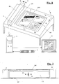
- the Figures 1-4 show a preferred realization of the scanning device. In its general structure, it corresponds to the usual measuring apparatuses, such as those typically used in the graphic industry for pointwise photoelectric measurement of printed sheets taken from a printing process. Such Sheets are also equivalently referred to as a measuring object or sample.
- the scanning device comprises a substructure in the form of a measuring table MT with a usually inclined rectangular surface on which the measuring object S - the printed sheet to be measured - can be positioned.
- the print sheet S typically includes some (here four, for example) plots P1-P4 and one (or more) colorimeters CMS.
- stops are provided on the measuring table MT.
- the fixation of the measuring object S on the measuring table MT is preferably carried out by electrostatic means or by means of known suction mechanisms.
- an elongated measuring beam or measuring carriage MC is arranged, on or in which a measuring device MD (FIG. Fig.2 ) is located.
- the measuring carriage MC extends over the depth of the measuring table MT in the coordinate direction y and is linearly movable back and forth over its width in the coordinate direction x, wherein corresponding drive and control devices are provided on the measuring carriage MC and on or below the measuring table MT.
- the drive device is indicated only symbolically in the drawing by the reference numeral D, the mobility of the measuring carriage MC in the x direction by the arrow A1.
- the actual measuring device MD can be raised and lowered relative to the measuring table surface in the direction of the coordinate axis z by means of conventional driving devices, not shown, and in certain embodiments also in the direction of the coordinate axis y (limited). These two possibilities of movement are in Fig. 2 symbolized by the arrows A2 and A3.
- a white reference WR On the measuring table MT is parallel to the measuring carriage MC a white reference WR. This serves for the calibration of the measuring device MD. Calibration is typically performed prior to each run, with the MD measuring device measuring the white reference. The white reference was previously measured (typically in the factory) using an external device and the measured values stored in the memory of the scanning device, usually in the computer C. Such calibration is common in spectrophotometers and, as such, prior art.
- the scanning device further comprises a processing device in the form of a (possibly also external) computer C with a keyboard K and a color monitor M.
- the computer C works together with a measuring and drive control, not shown here, on the measuring table MT or in the measuring carriage MC and processes the measurement signals generated by the measurement device MD located in the measurement carriage MC and supplied to it via the measurement and drive control MDC, wherein it can display the image information of the sampled measurement object S on the monitor M, among other things.
- the computer C can also initiate and control the movements of the measuring carriage MC and the measuring device MD located therein via the measuring and drive control.
- the scanning corresponds to the extent of the prior art, as for example by commercially available devices from Heidelberger Druckmaschinen AG or by the US-A 6,028,682 (corresponding DE-A-196 50 223 ) given is.
- the mechanical design and the realization of the motorized movability of measuring carriages MC and measuring device MD are in the US-A 6,028,682 described in detail, so that the expert in this regard requires no further explanation. It is understood that the measuring carriage MC can also be arranged parallel to the coordinate direction x, in which case all other orientations and directions of movement would likewise have been rotated by 90 °.
- the measuring device MD located in the measuring carriage MC comprises as the essential components an illumination device for exposing the measurement object to illumination light, pick-up optics for collecting the measurement light remitted by the object to be measured, and a wavelength range-selective photoelectric receiver device for converting the remitted measurement light into electrical measurement signals. These elements are used for pixel-by-pixel scanning of the entire printed sheet and are referred to collectively below as the image measuring unit.
- the measuring device MD is in addition to the above-mentioned image measuring unit still equipped with an independent spectral measuring head for the spectral measurement of individual pixels, as in the Fig. 3 is indicated schematically.
- This spectral measuring head 300 is independent of the other components via a motor drive indicated symbolically in the figure by an arrow A4 Measuring device in y-direction movable and thus in connection with the movement of the measuring carriage MC in x-direction over any pixel of the object to be positioned.
- the spectral measuring head 300 and its drive in the y-direction are also controlled by the measuring and control device.
- the spectral measuring head 300 is equipped with a polarization filter 301, which can be remotely introduced into the measuring beam path or removed therefrom, so that optional spectral measurements with and without polarization filter are possible.
- the movement of the polarizing filter 301 is in the Fig. 3 symbolized by an arrow A5.
- the polarizing filter 301 comprises two concentric parts whose polarization directions are crossed with respect to each other. The outer part is penetrated by the illumination beam path, the inner part of the measuring light beam path.
- more than one independent spectral measuring head can be provided in order, for example, to obtain measurements with and without polarization filter with two spectral measuring heads.
- the spectral measuring head 300 is used in practical applications for high-precision (spectral) measurements on relatively few selected picture elements of the measuring object S. Typically, this means that the color control strip CMS (usually present on printed sheets) Fig.1 ) measured. This can be done in a separate scanning or even together with the or one of the scanning passes of the measuring device MD. In both cases, due to the a priori not exactly known position of selected picture elements, it is particularly advantageous to interpret the image information captured by the measuring device in such a way that it can be used to position the independent spectral measuring head on specific picture elements. In particular, it is possible to determine the exact position of the color control strip CMS during the measuring process, and thus to position the independent spectral measuring head in a targeted manner over the picture elements of interest.
- the spectral measuring head is designed as a high quality color measuring system. It fulfills all requirements for measuring technology of international standards for color measurement (for example ISO 13655 or DIN 5033).
- the spectral individual measuring head 300 is designed with an annular or circular measuring geometry, so that no directional effects occur when the sample is rotated under the single spectral probe.
- An example of the realization of such a spectral measuring head is the spectrophotometer SpectroEye from GretagMacbeth AG, which can be used as a spectral measuring head in the measuring device.
- the spectral measuring head and the image measuring unit have an illumination spectrum in the measuring light without an ultraviolet (UV) component.
- the spectral measuring head 300 is also referred to below as a reference measuring device.
- the Fig. 4 shows the basic structure of the image measuring unit of the measuring device MD.
- the measuring device forms a total (with respect to wavelength ranges) multi-channel line scanner, wherein in the Fig. 4 For the sake of clarity, only the elements belonging to a color channel (wavelength range) are shown.
- a complete measuring device MD contains in the x-direction parallel to each other several of the in Fig. 4 shown configurations. For example, the measuring device may have six such configurations.
- the illumination device comprises per color channel a larger number of light sources 11 in the form of light-emitting diodes, which are lined up linearly in the y-direction. It also preferably comprises per each light source 11 a (cylindrical) collimator lens 12 and a continuous, in the longitudinal direction parallel to the y-coordinate extending slit diaphragm 13.
- the light sources 11 act on the measurement object S within a longitudinally parallel to the y-coordinate extending and at least over a part of the measuring object S extending illumination strip 15 with illumination light.
- each image element of the test object S to be scanned within the illumination strip 15 is exposed to illumination light at a defined angle of incidence (typically 45 ° / 0 °, eg DIN 165361, part 2) suitable for the color measurement.
- a defined angle of incidence typically 45 ° / 0 °, eg DIN 165361, part 2
- the collimator lenses 12 produce a nearly parallel beam path.
- the focal length of the lenses is chosen so that the divergence angle of the collimated beam path (in the y-direction) is less than or equal to 5-10 °.
- This implementation allows a largely uniform continuous line illumination.
- the illumination beam path is in Fig. 4 designated 11a.
- the slit diaphragm 13 limits the angle of incidence transversely to the longitudinal extension of the illumination strip, ie in the direction of the x-axis.
- the "white" radiating type Luxeon DS 25 from Lumileds Lighting LLC, San Jose, CA, USA can be used.
- the photoelectric receiver device comprises (per color channel) a line sensor 21 and an upstream color filter 22, which sensitizes the line sensor to its wavelength passage area.
- the line sensor consists of one or more so-called CIS elements (contact image sensor), which in turn each contain integrated on a chip in a straight line a large number of individual light sensors.
- a suitable CIS element is e.g. the type PI6045J of the company Peripheral Imaging Corporation, San Jose, CA, with a resolution of 600 dpi.
- the Aufpickoptikstoff comprise (per color channel) a line-shaped optical arrangement 31, which is preferably implemented by a substantially linear array of gradient index lenses, so-called. Selfoc lens arrays.
- Suitable selfoc lens arrays are sold by NSG.
- the linear optical arrangement 31 deflects the measuring light reflected from the picture elements of the measuring object S subjected to illumination light onto the associated measuring light.
- Line sensor 21 (measuring light beam path 21a).
- the optical assembly 31 is designed and arranged so that it captures the remitted measurement light from each scanned pixel only under a defined, suitable for color measurements Ausfallswinkel Anlagen (typically 0 ° +/- 5 °, eg DIN 165361, Part 2).
- the (per color channel) sampled pixel row is in Fig. 4 denoted by 16.
- the slit diaphragm 13 is positioned as close as possible to the measurement object S in the illumination beam path.
- the slit 13 limits the illuminated area on the measurement object. It typically has an opening width of 1 mm or smaller.
- the illuminated area of the measurement object (illumination strip 15) thereby has a width (in the x-direction) which is smaller than the field of view of the optical arrangement or selfoc-lens arrays 31 (in the x-direction). This improves the stray light suppression and enables density measurements of small high-density fields in a white environment.
- a fundamental problem of line lighting is that one point in the measuring field receives light from all the light sources (light-emitting diodes). The light from LEDs displaced along the line no longer hits 45 ° but with larger angles onto the measuring field. However, the larger angles violate the normalized color measurement geometry, which allows only illumination angles in the range 40 ° to 50 ° (45 ° +/- 5 °). Deviations from the standard geometry cause measurement errors, which are caused by a different surface effect and by other absorption paths through the ink layer.
- the effective illumination angle range must therefore be limited. This can be realized, for example, by means of a lamellar structure, which is arranged between the individual light-emitting diodes of a line and the measuring field.
- the slats must not be too big, because otherwise a lot of light is lost. Each measuring point only sees the light of a single LED within the permissible angular range.
- collimator lenses 12 which are provided along each light-emitting diode line source and preferably combined physically into lens arrays (a plurality of lenses made from a single plastic part).
- Each collimator lens 12 of a lens array collimates the light from mainly a light emitting diode 11 (or, when using many small light emitting diode chips, a limited array of multiple light emitting diode chips).
- the focal lengths of the collimator lenses 12 are selected such that the divergence angle and the contact angle of the illumination field in the longitudinal direction of the light-emitting diode line (y-direction) are less than +/- 10 °. In this way, an overlap and a homogeneous illumination intensity distribution is achieved within the illumination strip 15.
- the already mentioned diaphragm blades between the light-emitting diodes 11 prevent light from a light-emitting diode from being able to reach the test object via lenses of a neighboring light-emitting diode.
- the light-emitting diode line light source has a limited extent in the direction perpendicular to the line, so that in this dimension the requirements of the standard geometry are met even without additional optics.
- the slit 13 limits the width of the illumination strip 15.
- the scanning of a test object must be contactless.
- the bearing surface of the bow is usually not perfectly flat over the relatively large arc surface. Therefore, during scanning, changes in distance occur between the object to be measured and the measuring device. These must not influence the measured values. This requires the illumination and measuring optics to be pitch-independent over the tolerated range of a few tenths of a millimeter.
- the field of view of the measuring optics is over-illuminated by the illumination (the illumination strip 15 is wider than the width of the optical assembly 31 detected scan line 16). Since the detection angle of the optical assembly 31 must be very limited (according to the color measurement standards only coverage angle of +/- 5 ° are tolerable), the luminance or radiance is measured in the measuring field with the optical assembly, which is independent of the distance. The lighting must therefore only produce a constant, independent of the distance irradiance.
- the measuring device MD To measure the test object in several color channels, the measuring device MD, as already mentioned, with several configurations according to Fig. 4 fitted. These configurations (light sources 11, collimator lenses 12, slit 13, line sensor 21, color filter 22, linear optics assembly 31) are arranged parallel to each other at a small mutual distance (in the x direction) and differ only by different color filters 22nd
- the linear optical assemblies 31 and the line sensors 21 of the individual color channels are offset from one another in the x-direction. Therefore, each of the line sensors 21 receives measurement light from different pixel lines 16 of the measurement object S in the y-direction at a given time. However, moving the measurement carriage MC and thus the measurement device MD in the x-direction over the measurement object S causes all line sensors 21 to be sequential in time with measuring light from all pixel lines 16 of the measuring object S acted upon. If the measuring device MD is mounted on a printing press, the relative movement between the measuring device and the object to be measured results from the printed sheet passing under the measuring device.
- the Figures 1-4 show a preferred realization of the scanning device.
- the measuring carriage MC for example, only the spectral measuring head can be arranged.
- the image measuring unit can be installed directly in the printing press, such as in the known "web inspection" systems.
- the measuring carriage may only contain the image measuring unit or, equivalently, the image measuring unit is installed in the printing machine and an external hand-held measuring device is used as the spectral measuring head.
- the advantage of the first two arrangements is that the measurement can be carried out fully automatically with both units. In the latter arrangement, the printer has to perform the measurements with the external device by hand, which is time consuming and error prone.
- the measuring procedure is described below for the preferred scanning device of Figures 1-4 described.
- a corresponding measurement procedure can be implemented analogously.
- the printer places a printed sheet on the support below the measuring bar and triggers the image measurement.
- the measuring bar is moved over the template.
- the template is measured in whole or in part with the image measuring unit.
- the image measured values recorded by the image measuring unit without polarization filter (the entirety of the Measured values of all pixels of the printed sheet) are converted into remission values with the device color calibration and stored, for example, in an external computer C.
- the spectral measuring head is guided to reference measuring points and measures them with and without polarization filter 301.
- reference measuring points the fields of the colorimeter CMS on the printing sheet S are preferably used.
- predefined positions in the image are traced with the spectral measuring head and measured with and without polarization filter.
- the reflectance spectra acquired by the spectral measuring head with and without polarization filter at the reference measuring points serve as reference values and are likewise stored on the computer C.
- the measurement data of several printed sheets are recorded directly during the printing process and the corresponding measured values are fed to the external computer.
- the printer draws a sheet and automates or manually measures the colorimetric strip of the arc with the spectral probe, appropriate reference readings are generated for correction. They correspond to the current state of the printing press.
- the image measured values can be averaged over all sheets stored in the corresponding period.
- the advantage of the special scanning device according to the Figures 1-4 in that the spectral measurement head 300 generates reference values for the correction of the image measurement values on the same measurement object and simultaneously with the image measurement. Therefore, precise correction values (correction parameters) can be determined for each printing medium. The accuracy over a method that only works with predefined. Values works, is thereby significantly improved.
- the variety of different substrates (substrates, paper grades) is no longer a limitation.
- the temporal dependence of the measurement on the drying process of the ink is eliminated.
- the influence of fluorescence by different evaluation of optical brighteners in the substrate or by luminescent dyes in the color layer can be corrected.
- Another aspect is that the calculation of the correction values can be carried out automatically. The printer does not have paper quality Select more manually when defining the print parameters, which reduces the error rate.
- the measurement result is influenced by various influencing variables, as already explained in the introduction. These factors are e.g. Deviations of the measuring geometry of the image measuring device from the standard geometry, nature / structure of the surface of the test object and possibly the presence of optical brighteners in the printing medium (fluorescence effects). But even the absence of polarizing filters in the image measuring device is to be regarded as an influencing variable, as a result, thereby a different measurement result is achieved than in measurements using polarizing filters.
- the metrological effect of one or more of these influencing variables should, as a general rule, be compensated or eliminated as far as possible. More concretely, the corrected image measured values resulting from the correction should come as close as possible to image measured values which are measured under conditions in which the influencing variables are absent or have no effect.
- corrected image measured values which correspond to image measured values measured with polarization filters, are therefore to be calculated from the image measured values measured without polarization filter by the correction according to the invention.
- the influencing variable deviating measuring geometry does not exist. If the spectral measuring head with polarizing filter is used, the influencing variable missing polarization filter is also missing. Furthermore, the influence of the surface texture of the pressure medium has no effect. The spectral measuring head is therefore ideally suited as a reference measuring device.
- the conversion or correction of the image measured values according to the invention also takes place, for example, in the external computer.
- the correction according to the invention is advantageously carried out in two steps, each step already leading to an improvement on its own, but the combination of the two steps is optimal and therefore preferred.
- a first correction step the image measured values and the reference values of the spectral measuring head without polarization filter are matched to one another, thereby eliminating the media-dependent influence of the directional dependence and the measuring geometry.
- the measured values are thus optimally adapted to measured values, as measured with a standard-compliant color measuring device without polarization filter.
- this step may also include a fluorescence correction if the spectral individual measuring head and the image measuring unit have different illumination light sources.
- polarization filter image
- correction parameters 104 are determined on the basis of the reference values 101 and 102 of the image measuring unit and of the spectral measuring head and supplied to a correction model 105.
- the calculation of the correction parameters 104 and the correction 105 of the image measurement values are automatically performed every measurement.
- the correction model 105 can be implemented with different complexity.
- a simple correction model that allows reasonable improvement uses two parameters: an offset adjustment and a scaling factor.
- the scaling factor is a constant value for the correction of measuring geometry influences.
- the scaling factor is implemented as a characteristic function, which is dependent on the measured remission value and is used spectrally dependent in the field of fluorescence excitation.
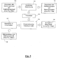
- FIG. 6 schematically shows the determination of the correction parameters for the media-dependent and Meßgeometrischen influencing variables and the fluorescence effects for unpolarized measured values. The procedure is described in more detail below.
- the reference values 102 of the spectral measuring head are adapted to the spectral resolution of the reference values 101 of the image measuring unit. This can be done by averaging over the wavelength interval of the corresponding image measurements.
- the weighting can also be carried out by means of a spectral evaluation function, for example the known normal observer functions for CIE XYZ or the evaluation functions for tristimulus values or density filters. This ev. Required spectral resolution adjustment is in the Figure 6 symbolized by block 102a.
- the reference values 101 and the optionally spectrally adjusted reference values 102 of the spectral measuring head are supplied as input variables to the parameter calculation stage 103.
- the correction model itself is structured in several ways. It includes an offset adjustment, a scaling and possibly a fluorescence and color layer correction.
- an offset value is subtracted from all measured data of the image measuring unit.
- the difference of the reference values 101 and 102 from reference fields of high density is formed and averaged.
- the mean determines the offset value.
- this process is indicated by the block 103a, the resulting offset value or offset correction parameter is denoted by 104a.
- scaling factor correction parameter 104b a mean scaling factor over all spectral measured values is calculated as scaling factor correction parameter 104b.
- the offset value of all measurement data of the image measurement unit is first subtracted, then all image measurement values are multiplied by the scaling factor. It must be ensured that no values outside the physically valid range occur. If this is the case, the calculated values are limited to the valid range.
- Fluorescence effects which are produced by different excitation of the optical brighteners in the substrate, must also be taken into account for the correction. These effects are media specific and can be combined with those in the Fig.1-4 be characterized and corrected corrected scanning device. This correction of the fluorescence effects is advantageously also carried out in the first correction stage.
- the fluorescence correction can be integrated into the scaling factor for matching to paper white. In this case, however, a common constant correction value is no longer sufficient for all spectral wavelengths.
- the correction must be performed differently for each spectral measured value in the active range of the fluorescence emission. For the optical brighteners, this corresponds to the spectral measured values in the wavelength range from 420 nm to 550 nm.
- the spectrally dependent scaling factors are calculated by dividing the reflectance values from the paper white measurements with the spectral measuring head and the image measuring unit in the active wavelength range of the fluorescence excitation.
- the characteristic correction corresponds to the multiplication of the spectral scaling factors on paper white with an additional factor, which depends on the measured reflectance value at the respective spectral support point.
- the characteristic can be equivalently implemented as a function of the remission value or the halftone value.
- c0, c1, c2, c3, ... represent the correction parameters.
- the correction parameters are determined by means of a known compensation calculation on the basis of the reference measured values 101 and 102.
- the compensation calculation is carried out or the correction parameters are calculated such that the reference values corrected with the correction model (using the parameters) correspond as well as possible to the reference values 102, eg in a manner known per se using the method of the smallest quadratic error.
- This part of the parameter calculation is in Fig. 6 symbolized by the block 103c, the corresponding characteristic correction parameters are denoted by 104c.
- the characteristic correction of the measurement value at a pixel is calculated as a weighted average of the correction parameters of each color.
- the weighting corresponds to the surface coverage coefficient of the color in the color structure of the sample.
- the color build-up in a pixel may be known from the pre-stage data or determined by known methods.
- the theory of Neugebauer can be applied. ( Hans EJ Neugebauer "The Theoretical Foundations of Multicolour Printing” Journal of Scientific Photography, Photophysics and Photochemistry, 36, 1937 ).
- the black component can be determined by a measured value in the near infrared range.
- the correction parameters are determined from the mean values of the correction parameters of the different individual colors and used for the conversion of all measured values.
- Fluorescence correction may alternatively be implemented using a physical model.
- the model of Kubelka-Munk with Saunderson correction for the surface effects describes the physical correlations when measuring a color layer on a diffusing substrate.
- the diffuse reflection coefficient of the substrate can be parameterized as a function of the effective integral absorption in the UV wavelength range.
- the second correction step is the transformation of the image measured values without polarization filter into equivalent measured values with polarization filter (polarization filter measured values).
- polarization filter measured values the measured values of each image pixel are transformed with a parameterized model whose parameters from the measured with and without polarization filter reference spectra of the spectral individual head of selected pixels are determined.
- selected picture elements those of the colorimeter CMS in the measurement object S are typically used.
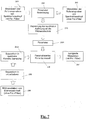
- the Fig. 7 clarifies these relationships.
- parameters 204 for a correction model 205 are formed in a parameter calculation stage 203 and supplied to the model. This then converts the image measurement data 206 (determined without polarization filter) of the image measurement unit into corresponding polarization filter measurement data 407. If necessary, the parameters are adapted in a step 210 to the spectral resolution of the image measuring unit.
- the image measurement data 206 is separated into individual colors (block 208) and further into spectral correction regions (block 209). The conversion to polarization filter measurement data 207 is performed automatically at each measurement.
- the correction to polarization filter measured values is more complex than the correction of the media dependence and the measurement geometry influence explained with reference to FIGS. 5 and 6.
- a spectral correction must be used for a colorimetric application.
- a correction with a value constant per color, as used for the conversion of the density values, is not sufficient. Therefore, a spectral measuring head must be used for the reference measurements to determine the spectral correction parameters.
- the second effect relates to the different degree of depolarization of the measuring light scattered by the sample.
- the degree of depolarization varies significantly between different types of substrates. This component can be described with a scaling factor correction.
- the degree of depolarization is influenced by the spectral absorption of the color layer, therefore this correction must be implemented depending on the spectral reflectance or the spectral density with a characteristic function similar to the fluorescence correction described above.
- the characteristics in the absorption region and in the transmission region of a color spectrum behave differently. Therefore, the correction is color-specific.
- the spectrum of each color is decomposed into at least two spectral ranges for which different correction factors are determined.
- the reference measured values of the color measurement strip which were previously determined with the spectral measurement head with and without polarization filter, are in the external computer; they are again denoted 201 and 202.
- the reference measurements include spot color measurements and raster tone measurements for each color as well as paper white measurement in both measurement modes.
- the reflectance spectra for each color are divided into the different spectral correction ranges.
- the subdivision into absorption and transmission range can be carried out with the full-tone spectra on the basis of a threshold value, for example a remission value of 0.2.
- an offset correction parameter 204a is determined for each spectral correction range. This value is determined by the difference in reflectance values for the highest density spectral measurements. Since the offset correction parameter is subtracted from the measurement without polarization filter, care must be taken that at higher densities in the image, no overcorrection to negative measurements may take place. If this risk exists, only a reduced component of this difference value is used as the offset correction parameter.
- the corresponding calculation stage is designated 203a.
- the paper white spectra (per spectral correction range) are matched by a spectral scaling factor.
- the scaling factor is formed by the quotient of the remission values with and without polarization filter and is designated 204b.
- the corresponding calculation stage is symbolized by block 203b.
- characteristic correction parameters 204c are calculated for each spectral correction range in a step 203c.
- the characteristic is parameterized in the absorption range as a function of the density value, ie as a function of the negative logarithm of the remission value.
- the characteristic curve can be implemented as a function of the remission value or the density value.
- the characteristic function can be described by a power function or by a polynomial approach, as in fluorescence correction.
- the parameters of the characteristic function are determined on the basis of the full tone, halftone tone and paper white measured values by compensation calculation. In the compensation calculation, the measured values used without polarization filter in the characteristic function and evaluated. The goal for the optimization is to determine the parameter set, which minimizes the quadratic differences to the reference measured values with polarization filter.
- the parameter set (the total of all correction parameters) is automatically determined on each sheet for each measurement. If characteristic measured values which are required for the determination of the characteristic correction are missing, a previously determined typical characteristic is assumed.
- the thus determined correction parameter set 204 is transferred to the correction model 205 and applied to the image measured values. If the image measurements are not in spectral form, the spectral correction parameters are first averaged over the corresponding spectral regions of the individual image measurements.
- the color composition is determined, i. which single colors are used with which area coverage.
- the color composition can be transmitted from the precursor data or, as described in connection with the fluorescence correction, calculated from the measured values.
- the spectral correction parameters in the different spectral regions are averaged weighted with the corresponding area coverage coefficients and applied to the image data analogously to the parameter calculation. If the color composition is missing, a best mean correction for the correction model is determined from the spectral correction parameter set for all individual colors, which is then used for all measured values.
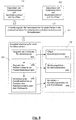
- the inventive conversion into polarization filter measured values can also be implemented without a separate spectral measuring head if the image measuring device is equipped with retractable polarization filters.
- the printed sheet is completely calibrated with the image measuring device without polarizing filter.
- a polarizing filter is pivoted into the lighting and collecting channel and in a separate special scanning with Approximately 10 times smaller scanning speed measured only a portion of the image with polarizing filter.
- This subarea advantageously includes the color control strip CMS or a part of the colorimeter. Due to the lower scanning speed, the measurement times (integration times) required for the use of polarization filters are approximately 10 times longer because of the loss of light.
- the image measuring device (with retracted polarizing filters) itself is used as the reference measuring device.
- the determination of the conversion parameters and the conversion of the measured values then takes place analogously to the method described in US Pat FIGS. 7 and 8th
- the measured values of the measuring device MD with and without polarization filter originating from the selected subregion of the image take the place of the method.
- a polarization filter consisting of two parts with crossed polarization directions is shown symbolically and denoted by 18. The adjustability in the beam paths and from the beam paths is symbolized by the arrow 18a.
Landscapes
- Physics & Mathematics (AREA)
- Spectroscopy & Molecular Physics (AREA)
- General Physics & Mathematics (AREA)
- Engineering & Computer Science (AREA)
- Biochemistry (AREA)
- Analytical Chemistry (AREA)
- Mathematical Physics (AREA)
- Theoretical Computer Science (AREA)
- Health & Medical Sciences (AREA)
- Life Sciences & Earth Sciences (AREA)
- Chemical & Material Sciences (AREA)
- Pathology (AREA)
- Immunology (AREA)
- General Health & Medical Sciences (AREA)
- Multimedia (AREA)
- Signal Processing (AREA)
- Spectrometry And Color Measurement (AREA)
- Investigating Or Analysing Materials By Optical Means (AREA)
Claims (15)
- Procédé de correction de valeurs de mesure d'image (106) d'un objet à mesurer (S) déterminées au moyen d'un dispositif de mesures d'image (MD) photoélectrique travaillant par points d'image, par rapport à au moins une grandeur d'influence ayant un effet sur le résultat de mesure avec l'objectif d'éliminer au moins partiellement l'effet de la technique de mesure de cette au moins une grandeur d'influence, où les valeurs de mesure d'image (106 ; 206) déterminées avec le dispositif de mesure d'image (MD) sont recalculées en valeurs de mesure d'image corrigées (108 ; 107) au moyen d'un modèle de correction (105 ; 205) paramétré par des paramètres de correction (104 ; 204) qui ne contiennent plus totalement ou au moins partiellement l'effet de la technique de mesure de la grandeur d'influence, où les paramètres de correction (104 ; 204) employés pour le modèle de correction (105 ; 205) paramétré sont estimés à l'aide de valeurs de mesure de référence (101, 102 ; 201 ; 202) mesurées à des points de mesure de référence choisis de préférence du même objet à mesurer (S) au moyen d'un dispositif de mesure de référence (300) et du dispositif de mesure d'image (MD), où un dispositif de mesure de référence (300) est employé, chez lequel l'au moins une grandeur d'influence n'est pas présente ou n'a aucun effet ou uniquement un effet de technique de mesure négligeable,
caractérisé en ce
qu'en tant que dispositif de mesure d'image (MD) un dispositif de mesure travaillant par points avec une géométrie de mesure s'écartant de la norme est employé et que des valeurs de mesure d'image (106 ; 206) sont corrigées en ce qui concerne l'influence de la géométrie de mesure déviant de la norme du dispositif de mesure d'image (MD), où, en tant que dispositif de mesure de référence (300), on emploie un dispositif de mesure avec une géométrie de mesure conforme à la norme, où la géométrie de mesure normalisée permet des angles d'éclairage dans la plage de 40 [degrés] à 50 [degrés]. - Procédé selon la revendication 1, caractérisé en ce que les paramètres de correction (104 ; 204) sont calculés au moyen d'un ajustement de courbe qui contient le modèle de correction (105 ; 205) et qui emploie en tant que grandeurs de départ les valeurs de mesure de référence (101, 102 ; 201, 202) mesurées avec le dispositif de mesure de référence (300) et le dispositif de mesure d'image (MD) et en tant que variables les paramètres de correction (104 ; 204), où l'ajustement de courbe est effectué de telle manière et les paramètres de correction (104 ; 204) y sont calculés de telle manière que les valeurs de mesure de référence (101) corrigées à l'aide du modèle de correction (105 ; 205) du dispositif de mesure d'image (MD) s'écartent possiblement peu des valeurs de mesure de référence (102) du dispositif de mesure de référence (300).
- Procédé selon l'une des revendications précédentes, caractérisé en ce que les valeurs de mesure d'image (106 ; 206) sont corrigées en ce qui concerne l'influence d'effets de fluorescence (103c).
- Procédé selon l'une des revendications précédentes, caractérisé en ce qu'en tant que dispositif de mesure d'image (MD), on emploie un dispositif de mesure travaillant par points sans filtre de polarisation et que les valeurs de mesure d'image (106 ; 206) sont corrigées en ce qui concerne l'influence d'une absence de filtre de polarisation dans le dispositif de mesure d'image (MD) et sont ainsi recalculées en valeurs de mesure d'image de filtre de polarisation, où, en tant que dispositif de mesure de référence (300), on emploie un dispositif de mesure avec des filtres de polarisation (301) commutables.
- Procédé selon la revendication 4, caractérisé en ce que des valeurs de mesure de référence (201 ; 202) sont mesurées au moyen du dispositif de mesure de référence (300) à des points de mesure de référence choisis, de préférence du même objet à mesurer (S), une fois avec et une fois sans filtre de polarisation (301) et que les paramètres de correction (104 ; 204) employés pour le modèle de correction (105 ; 205) paramétré sont déterminés à l'aide de ces valeurs de mesure de référence (201 ; 202) mesurées avec (201) et sans (202) filtre de polarisation (301).
- Procédé selon l'une des revendications 4 à 5, caractérisé en ce que des zones de correction spectrale sont mises en place et les valeurs de mesure d'image (106 ; 206) sont associées à ces zones de correction spectrale de sorte que des paramètres de correction spectrale séparés sont calculés pour chaque zone de correction spectrale et que les valeurs de mesure d'image (106 ; 206) de chaque zone de correction spectrale sont corrigées à l'aide des paramètres de correction associés à la zone de correction spectrale respective.
- Procédé selon l'une des revendications précédentes, caractérisé en ce que les valeurs de mesure d'image (106 ; 206) sont corrigées en deux étapes à l'aide d'un modèle de correction (105 ; 205) propre respectif.
- Procédé selon la revendication 7, caractérisé en ce que, dans une première étape, l'influence de la géométrie de mesure du dispositif de mesure d'image (MD), et éventuellement, les effets de fluorescence (103c), sont corrigés, et que, dans une deuxième étape, il y a un recalcul des valeurs de mesure d'image (108) corrigées dans la première étape en valeurs de mesure d'image de filtre de polarisation (208).
- Procédé selon l'une des revendications précédentes, caractérisé en ce que les valeurs de mesure d'image (106 ; 206) sont des valeurs de mesure spectrale.
- Procédé selon l'une des revendications précédentes, caractérisé en ce que, lors du calcul des paramètres de correction (104 ; 204), la résolution spectrale des valeurs de mesure de référence (102 ; 201) mesurées par le diapositif de mesure de référence (300) est ajustée à la résolution spectrale des valeurs de mesure (106 ; 206) mesurées par le dispositif de mesure d'image (MD).
- Procédé selon la revendication 1, caractérisé en ce que le modèle de correction (105 ; 205) paramétré comprend une correction d'offset (103a ; 203a), une mise à l'échelle (103b ; 203b) et une correction de caractéristiques spectrales (103c).
- Procédé selon la revendication 4, caractérisé en ce que le modèle de correction (105 ; 205) paramétré comprend une correction d'offset (103a ; 203a), une mise à l'échelle (103b ; 203b) et une correction de caractéristiques dépendantes d'une réémission ou de la densité (203c).
- Procédé selon l'une des revendications précédentes, caractérisé en ce qu'une tête de mesure spectrale avec une géométrie de mesure conforme à la norme et indépendante de la direction et dotée des filtres de polarisation (301) commutables est employée en tant que dispositif de mesure de référence (300).
- Procédé selon l'une des revendications précédentes, caractérisé en ce qu'en tant que dispositif de mesure d'image (MD) et que dispositif de mesure de référence (300), on emploie chaque fois un diapositif de mesure avec de la lumière d'éclairage sans UV.
- Procédé selon l'une des revendications précédentes, caractérisé en ce qu'un dispositif de balayage est employé, lequel comprend à la fois le dispositif de mesure d'image (MD) travaillant par points et le dispositif de mesure de référence (300).
Priority Applications (1)
| Application Number | Priority Date | Filing Date | Title |
|---|---|---|---|
| EP05808238.9A EP1805979B1 (fr) | 2004-10-28 | 2005-10-28 | Procede de correction de valeurs mesurees d'images |
Applications Claiming Priority (4)
| Application Number | Priority Date | Filing Date | Title |
|---|---|---|---|
| EP04025620A EP1655946A1 (fr) | 2004-10-28 | 2004-10-28 | Dispositif de balayage pour la mesure photoélectrique d'un objet à mesurer |
| CH2642005 | 2005-02-16 | ||
| EP05808238.9A EP1805979B1 (fr) | 2004-10-28 | 2005-10-28 | Procede de correction de valeurs mesurees d'images |
| PCT/EP2005/011591 WO2006045620A1 (fr) | 2004-10-28 | 2005-10-28 | Procede de correction de valeurs mesurees d'images |
Publications (2)
| Publication Number | Publication Date |
|---|---|
| EP1805979A1 EP1805979A1 (fr) | 2007-07-11 |
| EP1805979B1 true EP1805979B1 (fr) | 2019-06-19 |
Family
ID=35636791
Family Applications (2)
| Application Number | Title | Priority Date | Filing Date |
|---|---|---|---|
| EP05808238.9A Active EP1805979B1 (fr) | 2004-10-28 | 2005-10-28 | Procede de correction de valeurs mesurees d'images |
| EP05801762.5A Active EP1805978B1 (fr) | 2004-10-28 | 2005-10-28 | Dispositif de balayage pour la mesure photoélectrique d'un objet à mesurer |
Family Applications After (1)
| Application Number | Title | Priority Date | Filing Date |
|---|---|---|---|
| EP05801762.5A Active EP1805978B1 (fr) | 2004-10-28 | 2005-10-28 | Dispositif de balayage pour la mesure photoélectrique d'un objet à mesurer |
Country Status (4)
| Country | Link |
|---|---|
| US (2) | US7679785B2 (fr) |
| EP (2) | EP1805979B1 (fr) |
| JP (1) | JP2008518218A (fr) |
| WO (2) | WO2006045620A1 (fr) |
Families Citing this family (43)
| Publication number | Priority date | Publication date | Assignee | Title |
|---|---|---|---|---|
| US7924483B2 (en) * | 2006-03-06 | 2011-04-12 | Smith Scott T | Fused multi-array color image sensor |
| WO2007127269A2 (fr) * | 2006-04-25 | 2007-11-08 | Corporation For Laser Optics Research | Affichage multimédia en couleur en projection 3d |
| KR100755680B1 (ko) * | 2006-06-26 | 2007-09-05 | 삼성전자주식회사 | 색 변환 장치 및 방법 |
| DE102006048539A1 (de) * | 2006-10-13 | 2008-04-17 | Heidelberger Druckmaschinen Ag | Farbmesskopfpositionierungsvorrichtung |
| US7589837B2 (en) * | 2006-12-01 | 2009-09-15 | Xerox Corporation | Multiple tile calibration method for color sensors |
| DE102006056758A1 (de) * | 2006-12-01 | 2008-06-05 | Lithec Gmbh | Verfahren und Einrichtung zum Messen von Farb- und Helligkeitsanteilen |
| DE502006005469D1 (de) | 2006-12-18 | 2010-01-07 | X Rite Europe Gmbh | Spektraler fotoelektrischer Messwandler mit optischem Ablenkelement |
| EP1936945B1 (fr) | 2006-12-21 | 2011-02-09 | X-Rite Europe GmbH | Dispositif de balayage avec contrôle éléctronique de distance et sans detecteur de distance |
| DE502006007126D1 (de) | 2006-12-21 | 2010-07-15 | X Rite Europe Gmbh | Farbmesskopf und damit ausgestattete Abtastvorrichtung |
| JP4241843B2 (ja) * | 2007-02-20 | 2009-03-18 | 三菱重工業株式会社 | 膜質評価方法およびその装置ならびに薄膜製造システム |
| DE102008022770B4 (de) * | 2007-05-30 | 2018-01-11 | Heidelberger Druckmaschinen Ag | Verfahren zur Umrechnung von Farbmesswerten in polarisierter oder unpolarisierter Form |
| US7893394B2 (en) * | 2007-11-06 | 2011-02-22 | Ricoh Company Limited | Optical device, image reading device, and filter manufacturing method |
| US7986829B2 (en) * | 2007-11-29 | 2011-07-26 | Canon Kabushiki Kaisha | Generating a transformed interim connection space for spectral data |
| EP2335047A4 (fr) * | 2008-09-12 | 2012-02-22 | Ceramicam Ltd | Dispositif de balayage de surface |
| DE102010004417A1 (de) * | 2009-02-09 | 2010-09-02 | Heidelberger Druckmaschinen Ag | Konvertierung von filterlos gemessenen Farbmesswerten in mit Filtern gemessene Farbmesswerte und umgekehrt |
| JP5393216B2 (ja) * | 2009-03-24 | 2014-01-22 | オリンパス株式会社 | 蛍光観察システムおよび蛍光観察システムの作動方法 |
| JP5393215B2 (ja) * | 2009-03-24 | 2014-01-22 | オリンパス株式会社 | 蛍光観察装置、蛍光観察システムおよび蛍光観察装置の作動方法 |
| JP5440110B2 (ja) | 2009-03-30 | 2014-03-12 | 株式会社リコー | 分光特性取得装置、分光特性取得方法、画像評価装置、及び画像形成装置 |
| JP2010281808A (ja) * | 2009-05-01 | 2010-12-16 | Konica Minolta Sensing Inc | 照明装置およびそれを用いる反射特性測定装置 |
| JP5593635B2 (ja) * | 2009-05-18 | 2014-09-24 | 株式会社リコー | 画像評価装置 |
| JP5627259B2 (ja) * | 2009-05-22 | 2014-11-19 | キヤノン株式会社 | 撮像装置及び撮像方法 |
| JP5402441B2 (ja) * | 2009-09-14 | 2014-01-29 | 株式会社リコー | 反射型光学センサおよび画像形成装置 |
| JP5655437B2 (ja) * | 2009-09-14 | 2015-01-21 | 株式会社リコー | 分光特性取得装置 |
| US8194237B2 (en) * | 2009-10-15 | 2012-06-05 | Authentix, Inc. | Document sensor |
| JP5609068B2 (ja) | 2009-11-04 | 2014-10-22 | 株式会社リコー | 分光測定装置、画像評価装置及び画像形成装置 |
| JP5609611B2 (ja) | 2010-03-11 | 2014-10-22 | 株式会社リコー | 分光特性取得装置、画像評価装置、及び画像形成装置 |
| US8532449B2 (en) * | 2010-05-06 | 2013-09-10 | Intel Corporation | Wafer integrated optical sub-modules |
| US8799769B2 (en) * | 2011-02-08 | 2014-08-05 | Ebay Inc. | Application above-the-fold rendering measurements |
| US8995034B2 (en) * | 2011-06-20 | 2015-03-31 | Samsung Electronics Co., Ltd. | Image forming apparatus and method of color revising |
| JP6051543B2 (ja) | 2012-03-09 | 2016-12-27 | 株式会社リコー | 分光計測装置、画像評価装置及び画像形成装置 |
| US9060078B2 (en) * | 2012-05-30 | 2015-06-16 | Ricoh Company, Ltd. | Printer consistency measurement, evaluation and correction |
| EP2930494B1 (fr) | 2012-11-06 | 2021-08-04 | X-Rite Switzerland GmbH | Appareil de mesure portatif destiné à saisir l'aspect visuel d'un objet de mesure |
| WO2014097489A1 (fr) * | 2012-12-21 | 2014-06-26 | グローリー株式会社 | Capteur spectral |
| JP6232831B2 (ja) | 2013-08-15 | 2017-11-22 | 株式会社リコー | 分光特性取得装置、画像評価装置及び画像形成装置 |
| US10828636B2 (en) * | 2016-10-25 | 2020-11-10 | Fannin Partners Llc | Automated remotely instructed driving of an assay |
| JP6550743B2 (ja) | 2014-02-20 | 2019-07-31 | 株式会社リコー | 分光特性取得装置、画像評価装置及び画像形成装置 |
| JP2015161716A (ja) * | 2014-02-26 | 2015-09-07 | 日本電気株式会社 | 光学フィルタ、光モジュール、光通信システム、および光結合方法 |
| NO337769B1 (no) | 2014-10-14 | 2016-06-20 | Hexagon Raufoss As | Fremgangsmåte og verktøy for produksjon av en klemlinjefri liner |
| TWI616692B (zh) * | 2014-12-29 | 2018-03-01 | 鴻海精密工業股份有限公司 | 光纖連接器及光耦合透鏡 |
| US9869590B2 (en) * | 2015-05-29 | 2018-01-16 | Xerox Corporation | Spatially-resolved FWA spectrophotometer using micropatterned optical filters |
| JP2017207427A (ja) | 2016-05-20 | 2017-11-24 | セイコーエプソン株式会社 | 測定装置、及び印刷装置 |
| US10218926B2 (en) * | 2016-07-21 | 2019-02-26 | Christie Digital Systems Usa, Inc. | Device, system and method for cross-talk reduction in visual sensor systems |
| CN112881305B (zh) * | 2021-01-14 | 2022-11-25 | 河南天子铝业有限公司 | 一种用于铝型材的快速检测设备 |
Family Cites Families (11)
| Publication number | Priority date | Publication date | Assignee | Title |
|---|---|---|---|---|
| JPS5672573A (en) * | 1979-11-19 | 1981-06-16 | Ricoh Co Ltd | Self-scanning type photodiode array and its picture information read system |
| ATE20620T1 (de) * | 1982-04-10 | 1986-07-15 | Hell Rudolf Dr Ing Gmbh | Verfahren und vorrichtung zur dichtemessung von farbschichten noch feuchter druckfarbe. |
| US5330799A (en) * | 1992-09-15 | 1994-07-19 | The Phscologram Venture, Inc. | Press polymerization of lenticular images |
| US5963333A (en) * | 1996-09-12 | 1999-10-05 | Color Savvy Systems Limited | Color sensor |
| DE19650223A1 (de) * | 1996-12-04 | 1998-06-10 | Heidelberger Druckmasch Ag | Abtastvorrichtung zur bildelementweisen fotoelektrischen Ausmessung eines Messobjekts |
| DE29918640U1 (de) | 1999-10-22 | 2000-02-17 | MAN Roland Druckmaschinen AG, 63075 Offenbach | Messvorrichtung für die Qualitätskontrolle von Druckprodukten |
| US6262804B1 (en) * | 2000-02-04 | 2001-07-17 | X-Rite, Incorporated | Handheld color measurement instrument |
| US6597454B1 (en) | 2000-05-12 | 2003-07-22 | X-Rite, Incorporated | Color measurement instrument capable of obtaining simultaneous polarized and nonpolarized data |
| US6633382B2 (en) * | 2001-05-22 | 2003-10-14 | Xerox Corporation | Angular, azimuthal and displacement insensitive spectrophotometer for color printer color control systems |
| WO2005050148A2 (fr) * | 2003-11-18 | 2005-06-02 | Octadem Technologies | Lecteurs de spectre compacts pour determination precise des couleurs |
| JP4172432B2 (ja) * | 2004-07-23 | 2008-10-29 | セイコーエプソン株式会社 | 画像読み取り装置 |
-
2005
- 2005-10-28 WO PCT/EP2005/011591 patent/WO2006045620A1/fr active Application Filing
- 2005-10-28 EP EP05808238.9A patent/EP1805979B1/fr active Active
- 2005-10-28 JP JP2007538342A patent/JP2008518218A/ja not_active Withdrawn
- 2005-10-28 US US11/666,369 patent/US7679785B2/en active Active
- 2005-10-28 US US11/666,365 patent/US7671992B2/en active Active
- 2005-10-28 WO PCT/EP2005/011592 patent/WO2006045621A1/fr active Application Filing
- 2005-10-28 EP EP05801762.5A patent/EP1805978B1/fr active Active
Non-Patent Citations (1)
| Title |
|---|
| None * |
Also Published As
| Publication number | Publication date |
|---|---|
| EP1805979A1 (fr) | 2007-07-11 |
| WO2006045621A8 (fr) | 2006-07-20 |
| US7671992B2 (en) | 2010-03-02 |
| US7679785B2 (en) | 2010-03-16 |
| EP1805978B1 (fr) | 2013-12-04 |
| US20090091760A1 (en) | 2009-04-09 |
| WO2006045621A1 (fr) | 2006-05-04 |
| EP1805978A1 (fr) | 2007-07-11 |
| US20070260413A1 (en) | 2007-11-08 |
| WO2006045620A1 (fr) | 2006-05-04 |
| JP2008518218A (ja) | 2008-05-29 |
Similar Documents
| Publication | Publication Date | Title |
|---|---|---|
| EP1805979B1 (fr) | Procede de correction de valeurs mesurees d'images | |
| EP1180898B1 (fr) | Méthode et dispositif pour la mesure colorimétrique d'un document bidimensionnel | |
| EP1744884B1 (fr) | Procede pour determiner des valeurs de densite et/ou d'encrage et dispositif d'impression pour la mise en oeuvre dudit procede | |
| EP0884178B1 (fr) | Procédé pour reguler l'encrage dans une machine d'impression | |
| EP0713447B1 (fr) | Dispositif de verification d'image d'un produit imprime | |
| DE60216664T2 (de) | Spektrophotometer zur Farbsteuerung eines Farbdruckgeräts, unempfindlich gegen Winkel-, Azimuth- und Abstandsänderung | |
| EP1694049B1 (fr) | Colorimètre et tête de mesure associée | |
| EP1213569B1 (fr) | Dispositif pour la mesure pixel par pixel d'un objet de mesure plat | |
| EP1936337A1 (fr) | Tête manométrique et dispositif de balayage et dispositif de balayage équipé de celle-ci | |
| US7000544B2 (en) | Measurement and regulation of inking in web printing | |
| DE19802920B4 (de) | Verfahren und Vorrichtung zur Farbregelung in Druckmaschinen | |
| EP0505769B1 (fr) | Procédé de détermination du recouvrement de la surface d'un modèle, particulièrement une plaque, et dispositif pour exécuter ce procédé | |
| EP1857280B1 (fr) | Presse rotative dotée d'au moins un système d'encrage et un système de mesure en ligne des couleurs | |
| DE102007041673B4 (de) | Verfahren zur Gewinnung von Druckbild- oder Druckplatteninformationen | |
| EP1512531A1 (fr) | Système de régulation d'encrage pour machines d'impression | |
| EP2034286B1 (fr) | Méthode de contrôle d'un processus d'impression utilisant un système de mesure spectral comprenant un modulateur spatial de lumière | |
| EP4195645B1 (fr) | Procédé de mesure de la densité spectrale de couleur dans l'impression couleur | |
| EP1655946A1 (fr) | Dispositif de balayage pour la mesure photoélectrique d'un objet à mesurer | |
| DE19939162A1 (de) | Verfahren für die wahlweise farbmetrische oder densitometrische Analyse von Bildpunkten mehrfarbiger, in ein Meßfeld gemeinsam angeordneter Rasterstrukturen auf Druckerzeugnissen und portables Densitometer und Farbmeßgerät |
Legal Events
| Date | Code | Title | Description |
|---|---|---|---|
| PUAI | Public reference made under article 153(3) epc to a published international application that has entered the european phase |
Free format text: ORIGINAL CODE: 0009012 |
|
| 17P | Request for examination filed |
Effective date: 20070328 |
|
| AK | Designated contracting states |
Kind code of ref document: A1 Designated state(s): CH DE FR GB IT LI |
|
| DAX | Request for extension of the european patent (deleted) | ||
| RBV | Designated contracting states (corrected) |
Designated state(s): CH DE FR GB IT LI |
|
| 17Q | First examination report despatched |
Effective date: 20100517 |
|
| RAP1 | Party data changed (applicant data changed or rights of an application transferred) |
Owner name: X-RITE SWITZERLAND GMBH |
|
| GRAP | Despatch of communication of intention to grant a patent |
Free format text: ORIGINAL CODE: EPIDOSNIGR1 |
|
| INTG | Intention to grant announced |
Effective date: 20190109 |
|
| GRAS | Grant fee paid |
Free format text: ORIGINAL CODE: EPIDOSNIGR3 |
|
| GRAA | (expected) grant |
Free format text: ORIGINAL CODE: 0009210 |
|
| AK | Designated contracting states |
Kind code of ref document: B1 Designated state(s): CH DE FR GB IT LI |
|
| REG | Reference to a national code |
Ref country code: GB Ref legal event code: FG4D Free format text: NOT ENGLISH |
|
| REG | Reference to a national code |
Ref country code: CH Ref legal event code: EP |
|
| REG | Reference to a national code |
Ref country code: DE Ref legal event code: R096 Ref document number: 502005016052 Country of ref document: DE |
|
| PG25 | Lapsed in a contracting state [announced via postgrant information from national office to epo] |
Ref country code: IT Free format text: LAPSE BECAUSE OF FAILURE TO SUBMIT A TRANSLATION OF THE DESCRIPTION OR TO PAY THE FEE WITHIN THE PRESCRIBED TIME-LIMIT Effective date: 20190619 |
|
| REG | Reference to a national code |
Ref country code: CH Ref legal event code: PL |
|
| REG | Reference to a national code |
Ref country code: DE Ref legal event code: R097 Ref document number: 502005016052 Country of ref document: DE |
|
| PLBE | No opposition filed within time limit |
Free format text: ORIGINAL CODE: 0009261 |
|
| STAA | Information on the status of an ep patent application or granted ep patent |
Free format text: STATUS: NO OPPOSITION FILED WITHIN TIME LIMIT |
|
| PG25 | Lapsed in a contracting state [announced via postgrant information from national office to epo] |
Ref country code: LI Free format text: LAPSE BECAUSE OF NON-PAYMENT OF DUE FEES Effective date: 20191031 Ref country code: CH Free format text: LAPSE BECAUSE OF NON-PAYMENT OF DUE FEES Effective date: 20191031 |
|
| 26N | No opposition filed |
Effective date: 20200603 |
|
| GBPC | Gb: european patent ceased through non-payment of renewal fee |
Effective date: 20191028 |
|
| PG25 | Lapsed in a contracting state [announced via postgrant information from national office to epo] |
Ref country code: GB Free format text: LAPSE BECAUSE OF NON-PAYMENT OF DUE FEES Effective date: 20191028 Ref country code: FR Free format text: LAPSE BECAUSE OF NON-PAYMENT OF DUE FEES Effective date: 20191031 |
|
| PGFP | Annual fee paid to national office [announced via postgrant information from national office to epo] |
Ref country code: DE Payment date: 20241021 Year of fee payment: 20 |