EP1803979A2 - Steuerung für Automatikgetriebe, Verfahren dafür und Automatikgetriebe - Google Patents
Steuerung für Automatikgetriebe, Verfahren dafür und Automatikgetriebe Download PDFInfo
- Publication number
- EP1803979A2 EP1803979A2 EP06026444A EP06026444A EP1803979A2 EP 1803979 A2 EP1803979 A2 EP 1803979A2 EP 06026444 A EP06026444 A EP 06026444A EP 06026444 A EP06026444 A EP 06026444A EP 1803979 A2 EP1803979 A2 EP 1803979A2
- Authority
- EP
- European Patent Office
- Prior art keywords
- input
- clutch
- shifting
- shaft
- gear set
- Prior art date
- Legal status (The legal status is an assumption and is not a legal conclusion. Google has not performed a legal analysis and makes no representation as to the accuracy of the status listed.)
- Withdrawn
Links
Images


Classifications
-
- F—MECHANICAL ENGINEERING; LIGHTING; HEATING; WEAPONS; BLASTING
- F16—ENGINEERING ELEMENTS AND UNITS; GENERAL MEASURES FOR PRODUCING AND MAINTAINING EFFECTIVE FUNCTIONING OF MACHINES OR INSTALLATIONS; THERMAL INSULATION IN GENERAL
- F16H—GEARING
- F16H61/00—Control functions within control units of change-speed- or reversing-gearings for conveying rotary motion ; Control of exclusively fluid gearing, friction gearing, gearings with endless flexible members or other particular types of gearing
- F16H61/68—Control functions within control units of change-speed- or reversing-gearings for conveying rotary motion ; Control of exclusively fluid gearing, friction gearing, gearings with endless flexible members or other particular types of gearing specially adapted for stepped gearings
- F16H61/684—Control functions within control units of change-speed- or reversing-gearings for conveying rotary motion ; Control of exclusively fluid gearing, friction gearing, gearings with endless flexible members or other particular types of gearing specially adapted for stepped gearings without interruption of drive
- F16H61/688—Control functions within control units of change-speed- or reversing-gearings for conveying rotary motion ; Control of exclusively fluid gearing, friction gearing, gearings with endless flexible members or other particular types of gearing specially adapted for stepped gearings without interruption of drive with two inputs, e.g. selection of one of two torque-flow paths by clutches
-
- F—MECHANICAL ENGINEERING; LIGHTING; HEATING; WEAPONS; BLASTING
- F16—ENGINEERING ELEMENTS AND UNITS; GENERAL MEASURES FOR PRODUCING AND MAINTAINING EFFECTIVE FUNCTIONING OF MACHINES OR INSTALLATIONS; THERMAL INSULATION IN GENERAL
- F16H—GEARING
- F16H3/00—Toothed gearings for conveying rotary motion with variable gear ratio or for reversing rotary motion
- F16H3/006—Toothed gearings for conveying rotary motion with variable gear ratio or for reversing rotary motion power being selectively transmitted by parallel flow paths, e.g. dual clutch transmissions
-
- F—MECHANICAL ENGINEERING; LIGHTING; HEATING; WEAPONS; BLASTING
- F16—ENGINEERING ELEMENTS AND UNITS; GENERAL MEASURES FOR PRODUCING AND MAINTAINING EFFECTIVE FUNCTIONING OF MACHINES OR INSTALLATIONS; THERMAL INSULATION IN GENERAL
- F16H—GEARING
- F16H3/00—Toothed gearings for conveying rotary motion with variable gear ratio or for reversing rotary motion
- F16H3/02—Toothed gearings for conveying rotary motion with variable gear ratio or for reversing rotary motion without gears having orbital motion
- F16H3/08—Toothed gearings for conveying rotary motion with variable gear ratio or for reversing rotary motion without gears having orbital motion exclusively or essentially with continuously meshing gears, that can be disengaged from their shafts
- F16H3/087—Toothed gearings for conveying rotary motion with variable gear ratio or for reversing rotary motion without gears having orbital motion exclusively or essentially with continuously meshing gears, that can be disengaged from their shafts characterised by the disposition of the gears
- F16H3/093—Toothed gearings for conveying rotary motion with variable gear ratio or for reversing rotary motion without gears having orbital motion exclusively or essentially with continuously meshing gears, that can be disengaged from their shafts characterised by the disposition of the gears with two or more countershafts
-
- F—MECHANICAL ENGINEERING; LIGHTING; HEATING; WEAPONS; BLASTING
- F16—ENGINEERING ELEMENTS AND UNITS; GENERAL MEASURES FOR PRODUCING AND MAINTAINING EFFECTIVE FUNCTIONING OF MACHINES OR INSTALLATIONS; THERMAL INSULATION IN GENERAL
- F16H—GEARING
- F16H2306/00—Shifting
- F16H2306/40—Shifting activities
- F16H2306/46—Uncoupling of current gear
-
- F—MECHANICAL ENGINEERING; LIGHTING; HEATING; WEAPONS; BLASTING
- F16—ENGINEERING ELEMENTS AND UNITS; GENERAL MEASURES FOR PRODUCING AND MAINTAINING EFFECTIVE FUNCTIONING OF MACHINES OR INSTALLATIONS; THERMAL INSULATION IN GENERAL
- F16H—GEARING
- F16H2306/00—Shifting
- F16H2306/40—Shifting activities
- F16H2306/50—Coupling of new gear
-
- F—MECHANICAL ENGINEERING; LIGHTING; HEATING; WEAPONS; BLASTING
- F16—ENGINEERING ELEMENTS AND UNITS; GENERAL MEASURES FOR PRODUCING AND MAINTAINING EFFECTIVE FUNCTIONING OF MACHINES OR INSTALLATIONS; THERMAL INSULATION IN GENERAL
- F16H—GEARING
- F16H2306/00—Shifting
- F16H2306/40—Shifting activities
- F16H2306/52—Applying torque to new gears
-
- Y—GENERAL TAGGING OF NEW TECHNOLOGICAL DEVELOPMENTS; GENERAL TAGGING OF CROSS-SECTIONAL TECHNOLOGIES SPANNING OVER SEVERAL SECTIONS OF THE IPC; TECHNICAL SUBJECTS COVERED BY FORMER USPC CROSS-REFERENCE ART COLLECTIONS [XRACs] AND DIGESTS
- Y10—TECHNICAL SUBJECTS COVERED BY FORMER USPC
- Y10T—TECHNICAL SUBJECTS COVERED BY FORMER US CLASSIFICATION
- Y10T74/00—Machine element or mechanism
- Y10T74/19—Gearing
- Y10T74/19219—Interchangeably locked
- Y10T74/19251—Control mechanism
Definitions
- This invention relates to a vehicle control unit, control method, and automatic transmission.
- a conventional automatic transmission using a planetary gear type or parallel axes type shift mechanism changes gears by selecting, engaging or disengaging a combination of clutches that are individually provided for gear combinations of different gear ratios.
- This type of transmission is equipped with a torque converter. The torque converter can absorb starting and shifting shocks but is inefficient in shifting and reduces the fuel economy of the vehicle.
- an automated manual transmission has been developed by automating a parallel axes type transmission that has been used as a manual transmission (MT).
- This parallel axes type transmission can minimize clutch slippage by using friction clutches.
- this type provides fewer gears to be engaged and can be efficient in shifting and increase the fuel economy of the vehicle.
- a dual friction clutch transmission of the above example contains various control- and adjustment-related problems. If the clutch exchange cannot be controlled adequately because of a piece-to-piece variation of apparatus, improper transmission temperature, and dispersion of output torque of engine, the good drivability and riding comfort cannot be attained. Moreover, two friction clutches are required to make the transmission high efficient without torque interruption. This increases the production cost and weight of the transmission mechanism.
- This invention relates to a device or method of controlling a vehicle that is equipped with an automatic transmission which may comprise two input shafts, an output shaft, two input clutches that are engaged and disengaged to transmit rotational force from a drive source to the two input shafts, multiple gear sets which transmit drive force at respective gear ratios between the two input shafts and the output shaft, multiple shifting clutches to select a gear set which transmits the drive force among the multiple gear sets, and a friction clutch which transmits force between two input shafts.
- This invention can attain the good drivability and riding comfort that vehicle drivers want without using any complicated control and adjustment as in the dual friction clutch transmission.
- This invention proposes an automatic transmission; a unit and method of controlling thereof that can avoid torque interruptions during shifting without using any complicated control by providing at least one friction or electromagnetic clutch instead of the above dual friction clutches among multiple input shafts.
- a single friction clutch provided among multiple input shafts can continuously transmit torque to the driving wheels.
- one friction or electromagnetic clutch is provided between two transmission input shafts which are the outputs of two input clutches provided on the output shaft of the engine. This friction clutch absorbs the rotational speed difference that generates between the multiple input shafts in shifting and enables steady force transmission to the output shaft during shifting. Below will be explained some embodiments of this invention.
- Fig. 1 shows a configuration of a vehicle that is one embodiment of this invention.
- Transmission 2 is connected to prime mover 1 which gives driving force to a vehicle. Its output shaft 3 drives wheels 29 via a differential gear. Transmission 2 houses actuator group 56 to accomplish starting and shifting. Controller 31 is connected to actuator group 56. Controller 31 instructs input clutch actuator 51, friction clutch actuator 53, and shift actuator 52 to actuate clutches and the shift mechanism to accomplish starting and shifting.
- Electronic controlled throttle valve 30 is provided on engine 1 to control the output of the engine by a request signal sent from engine controller 33. It is also possible to control the engine output by changing ignition timing and fuel injection rate instead of the throttle valve.
- Controller 31 controls transmission torque and revolutions of actuator group 56 and temporarily controls the output of engine 1 by transferring information to and from engine controller 33.
- engine controller 33 and controller 31 are separate, but one of these controllers can contain the function of the other or a single integrated controller can contain all functions of these controllers. In other word, if one of the controllers of this invention contains functions of the other controller, not all controllers are always required. This applies to the other embodiments of this invention.
- this embodiment uses a rear-wheel-drive vehicle as an example, but can apply to a front-wheel-drive vehicle by placing engine 1, transmission 2, and output shaft perpendicular to the movement of the vehicle. Furthermore, this embodiment can apply to a four-wheel-drive vehicle by dividing the output shaft to both front and rear wheels.
- Fig. 2 shows the major configuration of actuator group 56 of Fig. 1.
- actuator group 56 When receiving a command from controller 31, actuator group 56 operates two input clutches (first mesh type clutch 5 and second mesh type clutch 6), three shifting clutches (first shifting mesh type clutch 26, second shifting mesh type clutch 27, and third shifting mesh type clutch 28), and one friction clutch 32 and sends the operating states of these clutches to controller 31.
- first mesh type clutch 5 and second mesh type clutch 6 three shifting clutches (first shifting mesh type clutch 26, second shifting mesh type clutch 27, and third shifting mesh type clutch 28), and one friction clutch 32 and sends the operating states of these clutches to controller 31.
- shifting clutches is not limited to three. It can be any.
- Fig. 3 shows the configuration of transmission 2 of Fig. 1.
- the output of engine 1 that is a drive source is connected to the main input shaft 19 of the transmission.
- First input gear 4 is fixed to the main input shaft 19 of the transmission.
- First input mesh type clutch 5 can selectively transmit force to first input shaft 6.
- first input gear 4 can selectively transmit force to third shaft 9 via second input mesh type clutch 8.
- First input shaft 6 fixes 1st drive gear 11, 3rd drive gear 12, 5th drive gear 13, and one of friction clutches 32 thereon.
- Second input shaft 15 is driven by engagement of second output gear 14 and 4th drive gear 16. Second input shaft 15 fixes 2nd drive gear 18, reverse drive gear 17, and the other of friction clutches 32 thereon.
- the above drive gears are respectively engaged with 1st driven gear 20, 3rd driven gear 21, 5th driven gear 22, reverse driven gear 23, 2nd driven gear 24 and 4th driven gear 25.
- 1st shifting mesh type clutch 26, 2nd shifting mesh type clutch 27, and 3rd shifting mesh type clutch 28 selectively transmit drive force to output shaft 3.
- gear set a combination of a drive gear (e.g. 1st drive gear 11) and a driven gear (e.g. 1st driven gear 20) is called a gear set.
- gear 14 can be engaged any gear as long as the gear can drive second input shaft 15.
- the gear ratio of first gear 4 and second gear and the gear ratio of gears that drive the second input shaft must be 1 respectively in this configuration.
- the actuator By a command from controller 31, the actuator (not shown in Fig. 3) actuates first input mesh type clutch 5, second mesh type clutch 8, first shifting mesh type clutch 26, second shifting mesh type clutch 27, third shifting mesh type clutch 28, and friction clutch 32 to transmit or disconnect drive force.
- this embodiment handles a transmission configuration of 5 speeds forward gear and 1 speeds reverse gear, this invention does not limit the number of gear positions as long as gear positions are not continuous on one input shaft.
- Fig. 4 shows how drive force is transmitted when the vehicle starts in Fig. 3.
- second mesh type clutch 8 In the vehicle stop state, second mesh type clutch 8 is engaged. (If the clutch has been disengaged, the clutch is engaged. If the clutch has been engaged, the clutch is kept engaged. This applies to the description below.) First shifting mesh type clutch 26 shifted to the 1st speed side to engage and the other shifting mesh type clutches are disengaged. Then, disengaged friction clutch 32 is gradually engaged. With this, the vehicle can start smoothly. When friction clutch 32 is completely engaged, first input gear 4 and first input shaft 6 rotate at the same speed and first input mesh type clutch 5 is ready to be engaged. Here, the clutch 5 is shifted to engage. In some cases (e.g. for special clutch tooth shapes), clutch engagement may be hard.
- Fig. 5 shows how drive force is transmitted when the vehicle is a steady-state running on 1st speed in Fig. 3.
- second input gear 7 and second input mesh type clutch 8 also have the same rotational speed. In this state, second input mesh type clutch 8 is disengaged. At or after this timing, friction clutch 32 that has ended force transfer is disengaged.
- Fig. 5 shows gear combinations for this steady-state running on 1st speed. It is possible to run the vehicle steadily only by disengaging friction clutch 32 without disengaging second input mesh type clutch 8. Judging from less fuel economy due to dragging of friction clutch 32 and the inertia of third shaft 9 in spite of higher shifting response, it is preferable to disengage third shaft 9 for higher transmission efficiency. It is also preferable to disengage only second input mesh type clutch 8 without disengaging friction clutch 32. Requirement of response or fuel economy is considered to select third shaft 9 or clutch 8 to be disengaged.
- Fig. 6 to Fig. 8 show how drive force is transmitted during up-shifting in Fig. 3.
- Third shifting mesh type clutch 28 is shifted to the 2nd speed position from the 1st speed position (Fig. 5). Then friction clutch 32 is gradually shifted to engage. As shown in Fig. 6, the 2nd-speed drive force gradually starts to advance via 2nd drive gear 18 and 2nd driven gear 24. As shown in Fig. 7, the torque via 1st drive gear 20 becomes very small (approx. 0 which is a preset torque). In this state, first shifting mesh type clutch 26 can be easily disengaged from the 1st-speed gear.
- Fig. 9 shows an operational timing diagram of Fig. 4 to Fig. 8.
- This diagram shows clutch and torque states while a vehicle starts to run, runs at the 1st speed, changes speed from 1st speed to 2nd speed, and runs at the 2nd speed. Note the behavior of the output shaft torque.
- the output shaft torque is not interrupted during shifting because there is a drive force transmission path even during shifting. However, the operation of the friction clutch only is not enough, causing a projection of the output shaft torque as indicated by a dotted line.
- the output shaft torque can have a smooth transition as indicated by a solid line by reducing the throttle valve opening independently of the accelerator operating.
- the engine torque is controlled by the throttle valve opening in this diagram, the other method such as control of ignition timing and fuel supply can be used to reduce the engine torque.
- this embodiment can perform smooth shifting while transmission of the output shaft torque is in progress.
- this embodiment describes up-shifting from the 1st speed position to the 2nd-speed position, a similar method can be applied to perform smooth shifting without interruption of the output shaft torque for all up-shifting operations using multiple input shafts.
- Fig. 10 to Fig. 13 show how drive force is transmitted when the vehicle performs down-shifting in Fig. 3.
- Fig. 10 shows a flow of drive force in the case of a steady-state running on 5th speed.
- Fig. 11 shows a flow of drive force immediately after shifting starts.
- friction clutch 32 is gradually shifted from the state of Fig. 10 to engage, the rotational speed of second input mesh type clutch 8 becomes equal to the rotational speed of second input gear 7 and second input mesh type clutch 8 is ready to be engaged.
- clutch engagement may be hard.
- Second shifting mesh type clutch 27 is disengaged from 5th driven gear 22 and/or friction clutch 32 is disengaged. This sets the steady-state running on 4th speed (see Fig. 13). After this, first input mesh type clutch 5 is engaged to be ready for next shifting. This improves the shifting response. Judging from less fuel economy due to dragging of friction clutch 32 and the inertia of first input shaft 6, first input mesh type clutch 5 is left disengaged. Requirement of response or fuel economy is considered to determine which clutch is to be disengaged.
- Fig. 14 shows an operational timing diagram of Fig. 10 to Fig. 13.
- This diagram shows clutch and torque states while a vehicle runs at the 5th speed, changes speed from 5th speed to 4th speed, and runs at the 4th speed. Note the behavior of the output shaft torque.
- the output shaft torque is not interrupted during shifting because there is a drive force transmission path even during shifting.
- this embodiment can perform smooth shifting while transmission of the output shaft torque is in progress.
- a similar method can be applied to perform smooth shifting without interruption of the output shaft torque for all down-shifting operations using multiple input shafts.
- Fig. 15 shows an example of configuration of controller 31 and engine controller 33 of Fig. 1.
- Controller 31 is built up as a control unit which is equipped with input section 60, output section 62, and arithmetic processing unit 61.
- engine controller 33 is built up as a control unit which is equipped with input section 63, output section 65, and computer 64.
- Each of these controllers inputs multiple vehicle status detection signals and outputs multiple actuator operation signals according to a control method which has been stored in the arithmetic processing unit.
- Fig. 16 shows a control flow chart of controller 31.
- Controller 31 reads information at Step 101 and judges whether shifting has started at Step 102. In judgment of whether shifting has started, controller 31 determines a gear position from velocity data and accelerator operating which are in the read information. When this determined gear position is not equal to the current gear position, shifting starts and control is transferred to Step 103. If the determined gear position is equal to the current gear position, shifting is suppressed and controller 31 stops processing.
- controller 31 judges whether the shifting is up-shifting or down-shifting at Step 103. In up-shifting, controller 31 implements the above up-shifting operation at Step 104. In down-shifting, controller 31 implements the above down-shifting operation at Step 105.
- Fig. 17 shows a configuration of transmission 2 which is a second embodiment of this invention.
- first input shaft 6 is hollow to concentrically contain second input shaft 15.
- the drive force from the engine is to the input shafts by second input mesh type clutch 8.
- the operation of this transmission is the same as that of the first embodiment, but the transmission of the second embodiment is smaller thanks to the hollow two-axis shaft configuration.
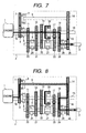
- Fig. 18 shows a sectional view of the input shaft of Fig. 17 as an example.
- the output from the engine is transmitted to sleeve gear 41 of second input mesh type clutch 8 through main transmission input shaft 19 and rotor 39.
- Sleeve gear 41 can be selectively engaged with mesh type gear 42 of second input shaft 15.
- First input mesh type clutch 5 on first input shaft 6 is so constructed to slide on first input shaft.
- sleeve gear 42 is constructed so as to be selectively engaged with mesh type gear 43 of rotor 39 to transmit the output of the engine to first input shaft 6.
- the first and second mesh type clutches are constructed to form a twin-clutch configuration.
- Fig. 19 shows a sectional view of transmission 2 which is a third embodiment of this invention.
- friction clutch 32 is hard to be operated if it is in the center of the transmission. In such a case, friction clutch 32 must be placed in the end of the transmission.
- one part of friction clutch 32 is provided on the end of second input shaft 15. Drive force from the engine is transmitted to first input shaft 6 through the other part of friction clutch 32, gear 48, gear 47, third shaft 46, gear 45, and gear 13.
- Fig. 20 shows a sectional view of transmission 2 which is a fourth embodiment of this invention.
- Embodiment 3 provides friction clutch 32 on one end of transmission, but output shaft 3 is provided between first input shaft 6 and second input shaft 15 or in the center (of the transmission).
- One part of friction clutch 32 is provided on second input shaft of friction clutch 32 and the other part of friction clutch 32 is connected to the first input shaft with a gear set of gears 48 and 49.
- This configuration does not use a hollow two-axis shaft structure, but is still compact and more simplified than the configuration of Fig. 19.
- Fig. 21 shows a sectional view of transmission 2 which is a fifth embodiment of this invention.
- This embodiment provides friction clutch 32 in the transmission of Fig. 20 closer to the engine.
- One part of friction clutch 32 is connected to second input shaft 15 with third shaft 51, gear 52, and gear 49.
- the other part of friction clutch 32 is connected to first input shaft 6 with gears 48 and 50.
- This embodiment is very effective when pipes to lubricate the friction clutch and actuator positions are very limited.
- an embodiment of this invention is a transmission which comprises multiple drive-line selective mechanisms which are connected to a drive source, multiple input shafts which are selectively engaged to transmit drive force or disengaged by the drive-line selective mechanisms, output shaft to output drive force, and one or more gear sets of a drive gear mounted on the input shaft and a driven gear which is engaged with the drive gear so that the gear may be selectively engaged to the output shaft or disengaged from the output shaft, or one or more gear sets of a drive gear mounted on the output shaft and a driven gear which is engaged with the drive gear so that the gear may be selectively engaged to the input shaft or disengaged from the input shaft ; wherein the transmission is equipped with a means that can continuously change the quantity of drive force transmitted between the input shafts.
- the embodiment can use friction clutches as the drive-line selective mechanisms, mesh type clutches or synchronous mesh type clutches as the drive-line selective mechanisms, and a friction clutch or electromagnetic clutch as the means that can continuously change the quantity of drive force.
- the transmission can be so constructed that gear sets provided on a single input shaft may not form consecutive gear positions, that a third shaft may be provided to receive drive force from at least one of the input shafts, and that there may be no difference between rotational speeds of the input shafts when a means that can continuously change the quantity of drive force is engaged.
- the transmission of this invention enables construction of input shafts of the concentric hollow two-axis shaft type, provision of a means that can continuously change the quantity of drive force transmitted on the third shaft, and connection of the means with the input shaft by mean of gear sets.
- An embodiment of this invention is an automatic transmission, a transmission controller, or a transmission controlling method, wherein when one of multiple drive-line selective mechanisms connected to a drive source is engaged and drive force is transmitted to the output shaft via some gear sets, another drive-line selective mechanism is engaged; and when a gear set which is provided on an input shaft connected to the other drive-line selective mechanism and different from the above gear set is selected and then the means capable of continuously changing the quantity of drive force is operated to increase the transmission torque, the drive force path is changed from the current gear set that transmits the drive force to a gear set of the higher speed position; and when the transmission torque of the current gear set is about 0, the current gear set is deselected and the gear set of the higher speed position is selected to transmit the drive force to the output shaft.
- An embodiment of this invention is an automatic transmission, a transmission controller, or a transmission controlling method in accordance with claim 15, wherein the means capable of continuously changing the quantity of drive force is gradually disabled to transmit torque after only the gear set of the low-speed position is selected to drive.
- the output of the drive source may be equal to the output shaft torque that is made by a gear set of the low-speed position when the transmission torque of the means capable of continuously changing the quantity of drive force is gradually decreased.
- a gear set of the lowest speed position half-engage a drive-line selective mechanism, and start to drive the vehicle when the means capable of continuously changing the quantity of drive force is disabled.
- this invention can provide a vehicle transmission which controls the engine, friction clutches and mesh type clutch clutches in cooperation to improve the fuel economy and reduce shifting shocks.
Landscapes
- Engineering & Computer Science (AREA)
- General Engineering & Computer Science (AREA)
- Mechanical Engineering (AREA)
- Control Of Transmission Device (AREA)
- Structure Of Transmissions (AREA)
Applications Claiming Priority (1)
| Application Number | Priority Date | Filing Date | Title |
|---|---|---|---|
| JP2005378169A JP2007177925A (ja) | 2005-12-28 | 2005-12-28 | 自動車の制御装置,制御方法、及び自動変速機 |
Publications (3)
| Publication Number | Publication Date |
|---|---|
| EP1803979A2 true EP1803979A2 (de) | 2007-07-04 |
| EP1803979A8 EP1803979A8 (de) | 2007-08-22 |
| EP1803979A3 EP1803979A3 (de) | 2011-01-05 |
Family
ID=37890538
Family Applications (1)
| Application Number | Title | Priority Date | Filing Date |
|---|---|---|---|
| EP06026444A Withdrawn EP1803979A3 (de) | 2005-12-28 | 2006-12-20 | Steuerung für Automatikgetriebe, Verfahren dafür und Automatikgetriebe |
Country Status (4)
| Country | Link |
|---|---|
| US (1) | US20070144288A1 (de) |
| EP (1) | EP1803979A3 (de) |
| JP (1) | JP2007177925A (de) |
| CN (1) | CN100487273C (de) |
Cited By (1)
| Publication number | Priority date | Publication date | Assignee | Title |
|---|---|---|---|---|
| DE102013109627B4 (de) | 2012-09-14 | 2018-08-30 | Subaru Corporation | Getriebe |
Families Citing this family (9)
| Publication number | Priority date | Publication date | Assignee | Title |
|---|---|---|---|---|
| WO2010122646A1 (ja) | 2009-04-23 | 2010-10-28 | トヨタ自動車株式会社 | 車両用変速機の変速制御装置 |
| JP5465614B2 (ja) * | 2010-06-17 | 2014-04-09 | Ntn株式会社 | 車両用モータ駆動装置および自動車 |
| US8439801B2 (en) | 2011-01-27 | 2013-05-14 | Schaeffler Technologies AG & Co. KG | Method for controlling an automated shift gearbox |
| JP5545778B2 (ja) * | 2012-08-08 | 2014-07-09 | 富士重工業株式会社 | 変速機 |
| JP5439555B2 (ja) * | 2012-08-08 | 2014-03-12 | 富士重工業株式会社 | 変速機 |
| JP6064517B2 (ja) * | 2012-10-26 | 2017-01-25 | アイシン精機株式会社 | 動力伝達装置 |
| DE102016223177B4 (de) * | 2016-11-23 | 2021-06-17 | Zf Friedrichshafen Ag | Verfahren zum Betreiben eines Fahrzeugantriebsstranges |
| KR102785690B1 (ko) * | 2019-09-11 | 2025-03-24 | 현대자동차주식회사 | 하이브리드 파워트레인 |
| CN113090718A (zh) * | 2020-01-08 | 2021-07-09 | 舍弗勒技术股份两合公司 | 变速器及两挡电桥驱动系统 |
Family Cites Families (13)
| Publication number | Priority date | Publication date | Assignee | Title |
|---|---|---|---|---|
| US4513631A (en) * | 1983-06-16 | 1985-04-30 | General Motors Corporation | Dual input clutch transmission |
| DE19824415A1 (de) * | 1998-05-30 | 1999-12-02 | Volkswagen Ag | Doppelwellengetriebe und ein Verfahren zu dessen Betrieb |
| DE59805014D1 (de) * | 1998-08-25 | 2002-09-05 | Ford Global Tech Inc | Wechselgetriebe in 3-Wellenbauweise, insbesondere für Kraftfahrzeuge |
| EP1270301A3 (de) * | 2001-06-19 | 2007-02-21 | Hitachi, Ltd. | Kraftfahrzeuggetriebe mit Schaltungen ohne Drehmoment Unterbrechung |
| JP3988428B2 (ja) * | 2001-10-09 | 2007-10-10 | 株式会社日立製作所 | 自動変速機,制御装置、および自動車 |
| DE10305241A1 (de) * | 2003-02-08 | 2004-09-23 | Zf Friedrichshafen Ag | Sechs- oder siebengängiges Doppelkupplungsgetriebe |
| US6832978B2 (en) * | 2003-02-21 | 2004-12-21 | Borgwarner, Inc. | Method of controlling a dual clutch transmission |
| JP3952977B2 (ja) * | 2003-03-19 | 2007-08-01 | 日産自動車株式会社 | 多段式自動変速機の変速制御装置 |
| JP4038460B2 (ja) * | 2003-09-04 | 2008-01-23 | 株式会社日立製作所 | アクティブシフト変速機,変速機制御装置、および自動車 |
| US7140267B2 (en) * | 2003-10-22 | 2006-11-28 | General Motors Corporation | Multi-speed dual clutch transmission |
| JP4375001B2 (ja) * | 2003-12-04 | 2009-12-02 | 株式会社日立製作所 | 自動車の駆動装置および駆動方法 |
| US7082850B2 (en) * | 2003-12-30 | 2006-08-01 | Eaton Corporation | Hybrid powertrain system |
| US7291087B2 (en) * | 2005-01-13 | 2007-11-06 | General Motors Corporation | Planetary manual transmission |
-
2005
- 2005-12-28 JP JP2005378169A patent/JP2007177925A/ja not_active Withdrawn
-
2006
- 2006-12-15 CN CNB2006101700482A patent/CN100487273C/zh not_active Expired - Fee Related
- 2006-12-20 EP EP06026444A patent/EP1803979A3/de not_active Withdrawn
- 2006-12-27 US US11/645,706 patent/US20070144288A1/en not_active Abandoned
Cited By (1)
| Publication number | Priority date | Publication date | Assignee | Title |
|---|---|---|---|---|
| DE102013109627B4 (de) | 2012-09-14 | 2018-08-30 | Subaru Corporation | Getriebe |
Also Published As
| Publication number | Publication date |
|---|---|
| CN1991201A (zh) | 2007-07-04 |
| CN100487273C (zh) | 2009-05-13 |
| US20070144288A1 (en) | 2007-06-28 |
| EP1803979A3 (de) | 2011-01-05 |
| JP2007177925A (ja) | 2007-07-12 |
| EP1803979A8 (de) | 2007-08-22 |
Similar Documents
| Publication | Publication Date | Title |
|---|---|---|
| CN105667491B (zh) | 用于混合动力车辆变速器的控制系统和方法 | |
| JP3598998B2 (ja) | ツィンクラッチ式歯車変速機の歯車打音防止装置 | |
| JP3826888B2 (ja) | 多段式自動変速機の変速制御装置 | |
| CN101173711B (zh) | 双离合器变速器的齿轮选择方法 | |
| CN105620460B (zh) | 用于混合动力车辆变速器的控制系统和方法 | |
| US7628720B2 (en) | Vehicle control apparatus and method | |
| EP2653754B1 (de) | Steuerungsvorrichtung für ein doppelkupplungsgetriebe und steuerverfahren für ein doppelkupplungsgetriebe | |
| JP2004308841A (ja) | 多段式自動変速機の変速制御装置 | |
| US20020035010A1 (en) | Transmission system for vehicle | |
| EP1803979A2 (de) | Steuerung für Automatikgetriebe, Verfahren dafür und Automatikgetriebe | |
| JP2005054938A (ja) | 車両の変速装置 | |
| JP2005195115A (ja) | 車両用変速機 | |
| EP2947355B1 (de) | Startkupplungssteuerungsvorrichtung für ein automatikgetriebe | |
| GB2433301A (en) | A method of controlling a powershift transmission during change-of-mind shifts | |
| JP2003278898A (ja) | 自動変速機 | |
| JP4533870B2 (ja) | ツインクラッチ式変速機の制御装置及び方法 | |
| JP2016002950A (ja) | 車両の動力伝達制御装置 | |
| JPH1137260A (ja) | ツインクラッチ式変速機の変速制御装置 | |
| JP2004324768A (ja) | 自動変速機 | |
| JP2006194405A (ja) | ツインクラッチ式マニュアルトランスミッションの変速制御装置 | |
| JP2003278913A (ja) | 車両用自動変速装置 | |
| JP2005180628A (ja) | マニュアルトランスミッションの自動変速制御装置 | |
| CN116906525A (zh) | 多档位换档变速机构及其控制方法以及车辆 | |
| JP2003014061A (ja) | 自動変速機 | |
| JP2005337149A (ja) | 自動変速機の制御装置 |
Legal Events
| Date | Code | Title | Description |
|---|---|---|---|
| PUAI | Public reference made under article 153(3) epc to a published international application that has entered the european phase |
Free format text: ORIGINAL CODE: 0009012 |
|
| AK | Designated contracting states |
Kind code of ref document: A2 Designated state(s): AT BE BG CH CY CZ DE DK EE ES FI FR GB GR HU IE IS IT LI LT LU LV MC NL PL PT RO SE SI SK TR |
|
| AX | Request for extension of the european patent |
Extension state: AL BA HR MK YU |
|
| RIN1 | Information on inventor provided before grant (corrected) |
Inventor name: KUROIWA, HIROSHI,C/O HITACHI CAR ENGINEERING CO., Inventor name: IBAMOTO, MASAHIKO,C/O HITACHI, LTD., INTELLECTUAL Inventor name: OZAKI, NAOYUKI,C/O HITACHI, LTD., INTELLECTUAL PRO |
|
| 17P | Request for examination filed |
Effective date: 20080331 |
|
| PUAL | Search report despatched |
Free format text: ORIGINAL CODE: 0009013 |
|
| AK | Designated contracting states |
Kind code of ref document: A3 Designated state(s): AT BE BG CH CY CZ DE DK EE ES FI FR GB GR HU IE IS IT LI LT LU LV MC NL PL PT RO SE SI SK TR |
|
| AX | Request for extension of the european patent |
Extension state: AL BA HR MK RS |
|
| RIC1 | Information provided on ipc code assigned before grant |
Ipc: F16H 61/688 20060101ALN20101130BHEP Ipc: F16H 3/093 20060101ALN20101130BHEP Ipc: F16H 3/00 20060101AFI20101130BHEP |
|
| STAA | Information on the status of an ep patent application or granted ep patent |
Free format text: STATUS: THE APPLICATION HAS BEEN WITHDRAWN |
|
| 18W | Application withdrawn |
Effective date: 20110523 |