EP1801463A2 - Schaltvorrichtung für ein Getriebe - Google Patents
Schaltvorrichtung für ein Getriebe Download PDFInfo
- Publication number
- EP1801463A2 EP1801463A2 EP06024481A EP06024481A EP1801463A2 EP 1801463 A2 EP1801463 A2 EP 1801463A2 EP 06024481 A EP06024481 A EP 06024481A EP 06024481 A EP06024481 A EP 06024481A EP 1801463 A2 EP1801463 A2 EP 1801463A2
- Authority
- EP
- European Patent Office
- Prior art keywords
- shift
- switching
- gate
- positions
- automatic
- Prior art date
- Legal status (The legal status is an assumption and is not a legal conclusion. Google has not performed a legal analysis and makes no representation as to the accuracy of the status listed.)
- Granted
Links
Images


Classifications
-
- F—MECHANICAL ENGINEERING; LIGHTING; HEATING; WEAPONS; BLASTING
- F16—ENGINEERING ELEMENTS AND UNITS; GENERAL MEASURES FOR PRODUCING AND MAINTAINING EFFECTIVE FUNCTIONING OF MACHINES OR INSTALLATIONS; THERMAL INSULATION IN GENERAL
- F16H—GEARING
- F16H59/00—Control inputs to control units of change-speed-, or reversing-gearings for conveying rotary motion
- F16H59/02—Selector apparatus
- F16H59/0204—Selector apparatus for automatic transmissions with means for range selection and manual shifting, e.g. range selector with tiptronic
-
- F—MECHANICAL ENGINEERING; LIGHTING; HEATING; WEAPONS; BLASTING
- F16—ENGINEERING ELEMENTS AND UNITS; GENERAL MEASURES FOR PRODUCING AND MAINTAINING EFFECTIVE FUNCTIONING OF MACHINES OR INSTALLATIONS; THERMAL INSULATION IN GENERAL
- F16H—GEARING
- F16H59/00—Control inputs to control units of change-speed-, or reversing-gearings for conveying rotary motion
- F16H59/02—Selector apparatus
- F16H2059/0295—Selector apparatus with mechanisms to return lever to neutral or datum position, e.g. by return springs
-
- F—MECHANICAL ENGINEERING; LIGHTING; HEATING; WEAPONS; BLASTING
- F16—ENGINEERING ELEMENTS AND UNITS; GENERAL MEASURES FOR PRODUCING AND MAINTAINING EFFECTIVE FUNCTIONING OF MACHINES OR INSTALLATIONS; THERMAL INSULATION IN GENERAL
- F16H—GEARING
- F16H61/00—Control functions within control units of change-speed- or reversing-gearings for conveying rotary motion ; Control of exclusively fluid gearing, friction gearing, gearings with endless flexible members or other particular types of gearing
- F16H61/22—Locking of the control input devices
-
- F—MECHANICAL ENGINEERING; LIGHTING; HEATING; WEAPONS; BLASTING
- F16—ENGINEERING ELEMENTS AND UNITS; GENERAL MEASURES FOR PRODUCING AND MAINTAINING EFFECTIVE FUNCTIONING OF MACHINES OR INSTALLATIONS; THERMAL INSULATION IN GENERAL
- F16H—GEARING
- F16H63/00—Control outputs from the control unit to change-speed- or reversing-gearings for conveying rotary motion or to other devices than the final output mechanism
- F16H63/40—Control outputs from the control unit to change-speed- or reversing-gearings for conveying rotary motion or to other devices than the final output mechanism comprising signals other than signals for actuating the final output mechanisms
- F16H63/42—Ratio indicator devices
-
- Y—GENERAL TAGGING OF NEW TECHNOLOGICAL DEVELOPMENTS; GENERAL TAGGING OF CROSS-SECTIONAL TECHNOLOGIES SPANNING OVER SEVERAL SECTIONS OF THE IPC; TECHNICAL SUBJECTS COVERED BY FORMER USPC CROSS-REFERENCE ART COLLECTIONS [XRACs] AND DIGESTS
- Y10—TECHNICAL SUBJECTS COVERED BY FORMER USPC
- Y10T—TECHNICAL SUBJECTS COVERED BY FORMER US CLASSIFICATION
- Y10T74/00—Machine element or mechanism
- Y10T74/20—Control lever and linkage systems
- Y10T74/20012—Multiple controlled elements
- Y10T74/20018—Transmission control
- Y10T74/20067—Control convertible between automatic and manual operation
-
- Y—GENERAL TAGGING OF NEW TECHNOLOGICAL DEVELOPMENTS; GENERAL TAGGING OF CROSS-SECTIONAL TECHNOLOGIES SPANNING OVER SEVERAL SECTIONS OF THE IPC; TECHNICAL SUBJECTS COVERED BY FORMER USPC CROSS-REFERENCE ART COLLECTIONS [XRACs] AND DIGESTS
- Y10—TECHNICAL SUBJECTS COVERED BY FORMER USPC
- Y10T—TECHNICAL SUBJECTS COVERED BY FORMER US CLASSIFICATION
- Y10T74/00—Machine element or mechanism
- Y10T74/20—Control lever and linkage systems
- Y10T74/20012—Multiple controlled elements
- Y10T74/20018—Transmission control
- Y10T74/20085—Restriction of shift, gear selection, or gear engagement
Definitions
- the present invention relates to a switching device for an automated or automatic transmission, in particular of a motor vehicle, having the features of the preamble of claim 1.
- Such a transmission is for example from the EP 0 416 227 A1 known and has a shift lever for selecting automatic shift stages and gears of the transmission, which can be converted from a stable starting position into a plurality of immediately adjacent labile shift positions for selecting the automatic shift stages and gears, from which it automatically returns to the starting position. Furthermore, a display is provided which is used to visualize the currently engaged gear and / or the currently activated automatic shift stage.
- the known switching device comprises two shift gates, which intersect in the stable starting position and each have on either side of the stable starting position one of the unstable switching positions.
- a transmission control assigns the starting position and the shift positions to the individual automatic shift stages which can be selected by deflecting or tapping the shift lever into the unstable shift positions.
- the automatic shift stages is also a manual shift stage, in which can be switched by forwards and backwards tapping the shift lever between the individual gears of the transmission.
- the automatic shift stages include a parking position in which a parking brake of the transmission is activated.
- the shift lever is adjustable in a shift gate having four juxtaposed stable shift positions, which are each associated with an automatic shift stage of the transmission.
- the outer stable switching positions which is designed as a manual shift stage
- border three labile switching positions one of which is configured as a forward-switching stage and arranged in the shift gate.
- the other two unstable switch positions are arranged on both sides of the stable manual shift position in a cross track, which the shift gate in the manual shift position crosses.
- the two unstable switching positions of the cross lane are used to upshift and downshift the gears.
- the other stable shift positions of the shift gate are an idle shift stage, a reverse shift stage, and a park shift stage.
- the DE 20 2004 004 151 U1 shows a switching device in which a shift lever in an automatic shift gate for switching between automatic shift stages is adjustable and can be transferred via a cross track in a tap shift gate, in which it is adjustable for switching between gears.
- the shift lever In the tip shift gate, the shift lever has a stable shift position, in which the shift lever automatically returns from all unstable shift positions of the three lanes.
- a shift lever is adjustable in two interconnected via a cross track switching lanes for selecting gears or automatic shift stages.
- the known switching device is monostable and has only a single stable switching position for the shift lever.
- the shift lever is manually deflected from its stable shift position in one or the other shift gate in the respective desired shift position. Subsequently, the lever returns automatically after releasing from any possible deflection position in the stable switching position.
- the present invention is concerned with the problem of providing for a switching device of the type mentioned an improved embodiment, which characterized in particular by easy handling and preferably by a high level of operational reliability.
- the invention is based on the general idea, the shift lever between two stable switching positions, namely the starting position and a rest position, adjustable to design, the shift lever can be transferred only in the starting position in a plurality of immediately adjacent labile switching positions. In this way, the stable rest position can be easily assigned a decoupled from normal driving transmission function.
- the switching device can be particularly easy to use and has increased reliability.
- the rest position is associated with a parking shift stage of the transmission, in which a parking brake of the transmission is activated.
- a parking brake of the transmission is activated.
- a locking button may be provided, which secures the displaced in the rest position shift lever in the rest position in the unactuated state and only in the actuated state, a lead out of the shift lever from the rest position permits.
- said locking button can be designed so that it secures the shifted in the initial position shift lever in the starting position in the actuated state and only in the unactuated state allows an adjustment of the shift lever in the adjacent labile switch positions. This measure also increases the reliability and ease of operation of the transmission, since when transferring the shift lever from the rest position to the starting position, an inadvertent deflection of the shift lever in one of the unstable switching positions is not possible.
- a further increase in comfort and increased reliability can be achieved in that the safety button allows only in the actuated state, a transfer of the shift lever from the starting position to the rest position. This makes it possible to avoid accidental transfer of the shift lever in the rest position during driving.
- a switching device 1 according to the invention comprises a shift lever 2, which is adjustable in a shift gate assembly 3, and a display 4 and a transmission control 5.
- the switching device 1 is used to actuate an automated or automatic transmission 6, preferably a motor vehicle.
- the shift gate assembly 3 which can also be referred to as a real shift gate configuration, comprises a first shift gate 7 and a second shift gate 8 intersecting the first shift gate 7.
- the first shift gate 7 is preferably oriented parallel to the vehicle longitudinal direction in the installed state and will therefore also be referred to as the longitudinal track 7 in the following designated.
- the second shift gate 8 is preferably oriented transversely to the vehicle longitudinal direction and is therefore also referred to below as the cross track 8. Longitudinal lane 7 and cross lane 8 are preferably perpendicular to each other.
- the real shift gate configuration 3 is designed such that it provides a stable starting position 9 and a plurality of unstable shift positions 10 to 13 for the shift lever 2.
- the labile switching positions 10 to 13 are arranged immediately adjacent to the stable starting position 9 and are characterized in that the deflected from the stable starting position 9 in one of the unstable switching positions 10 to 13 shift lever 2 automatically returns to the starting position 9.
- the switching device 1 is provided with corresponding return means.
- the starting position 9 is arranged centrally with respect to the switching positions 10 to 13.
- the shift lever 2 must be deflected from the starting position 9 for transferring into the shift position 10 forward, in the shift position 11 to the rear, in the shift position 12 to the left and in the shift position 13 to the right.
- the left shift position 12 and the right shift position 13 on the cross track 8 on both sides of the Starting position 9 while the front-switching position 10 and the rear-switching position 11 are arranged in the longitudinal axis 7 on both sides of the starting position 9.
- the shift gate assembly 3 comprises a rest position 14 designated as further stable switching position, in which the shift lever 2 from the initial position 9 can be transferred.
- the stable rest position 14 is also arranged in the longitudinal lane 7 and that end. Since there is no further cross track, the shift lever 2 can only be moved out of the rest position 14 in one direction, namely in the direction of the starting position 9.
- stable switching positions are symbolized by double circles, while labile switching positions are represented by single circles.
- the transmission control 5 assigns the stable starting position 9 and the unstable switching positions 10 to 13 automatic shift stages and / or gears of the transmission 6 to.
- an indicated by a double arrow electronic active connection 15 between the transmission control 5 and the shift gate assembly 3 is provided.
- the transmission control 5 is connected by an electronic operative connection 16 with the display 4.
- the display 4 serves to visualize the currently engaged gear and / or the currently activated automatic gear shift stage.
- the display 4 serves here for the visualization of all possible gears and automatic shift stages.
- the transmission 6 comprises, as automatic shift stages, a forward shift stage D, an idle shift stage N and a reverse shift stage R.
- a manual shift stage M is provided here in which, by deflecting the shift lever 2 into downshift positions adjacent thereto, so-called downshift position, characterized by a minus sign (-), and for upshifting, so-called upshift position, characterized by a plus sign (+), the individual gears (1) to (6) of the transmission 6 can be selected.
- the aforementioned shift positions, gears and automatic shift stages are electronically assigned via the transmission control 5 to the starting position 9 and to the adjacent four unstable shift positions 10 to 13.
- the transmission control 5 is on usual manner, for example, coupled via an indicated by a double arrow electronic operative connection 23 to the transmission 6.
- the transmission 6 comprises a parking shift stage P, in which a parking lock of the transmission 6 is activated.
- This parking shift stage P is assigned to the stable rest position 14.
- the park shift stage P of the rest position 14 is not assigned electronically via the transmission control 5, but mechanically.
- a corresponding mechanical operative connection 17 between the rest position 14 and the transmission 6 is symbolized in FIG. 1 by a double arrow.
- This mechanical operative connection 17 is realized for example by a cable.
- the switching device 1 preferably comprises exactly two stable switching positions, namely the starting position 9 and the rest position 14, as well as exactly four labile shift lever positions 10 to 13. About this total of 6 shift positions 9 to 14 all gears and automatic transmission stages of the transmission 6 can be selected.
- the transmission control 5 simulates a virtual shift gate configuration 18, which is visualized to the user via the display 4.
- the virtual shift gate configuration 18 comprises two parallel shift gates, namely an automatic shift gate 19 for selecting the automatic shift stages and a jog shift gate 20 for selecting the gears. Furthermore, a connecting lane 21 is provided, which extends transversely to the two shift gates 19, 20 and connects them together.
- the automatic shift gate 19 a plurality of virtual stable shift gate positions are simulated, to each of which one of the automatic shift stages, here the forward shift stage D, the reverse shift stage R and in between the idle shift stage N, is assigned.
- the jogging lane 20 includes only one virtual stable Shift gate position to which the manual shift stage M is assigned.
- the jog shift gate 20 on both sides of the manual shift stage M additionally includes two virtual labile shift gate positions to which the upshift position (+) and the downshift position (-) are assigned.
- the connection lane 21 is here arranged to virtually connect the manual shift stage M to the forward shift stage D.
- the display 4 visualizes the real stable rest position 14, which is assigned to the parking shift stage P.
- the display 4 preferably visualizes the shiftable forward gears of the transmission 6.
- the respective active automatic shift stage and the respectively engaged gear are symbolized by a ring filling the respective double circle.
- the shift lever 2 is in the rest position 14. This is assigned to the parking shift stage P, which is signaled on the display 4 by a corresponding emphasis.
- the switching device 1 is additionally equipped with a locking button 22, which is integrated in the embodiment shown here in the shift lever 2 and is formed or arranged on this.
- the fuse button 22 is unconfirmed.
- the safety button 22 is designed so that in its unactuated state of the displaced in the rest position 14 shift lever 2 is secured in the rest position 14 and thus is unadjustable. The parking shift stage P is thus effectively secured.
- the safety key 22 is actuated, eg by depression. In its actuated state, the safety button 22 releases the shift lever 2, so that it can be brought out of the rest position 14.
- the locking button 22 in the rest position 14 ver admiratorym shift lever 2, however, the parking shift stage P and thus the parking brake of the transmission 6 remains active.
- 4a to 4c show the displaced to the starting position 9 shift lever 2 when actuated lock button 22.
- the fuse button 22 is designed so that it secures the shifted in the starting position 9 shift lever 2 in the initial position 9 in the actuated state, and so in that it can not be transferred into the adjacent unstable switching positions 10 to 13.
- the shift lever 2 can be adjusted only between the rest position 14 and the starting position 9.
- the transmission control 5 automatically activates the idle shift stage N when the shift lever 2 is transferred from the rest position 14 into the starting position 9.
- the shift lever 2 can deflect from its initial position 9 in the labile switching positions 10 to 13, but not in the stable rest position 14th
- a further backup in the form of a locking device not shown here may be provided.
- the shift lever 2 may be e.g. only be transferred from the rest position 14 in the starting position 9 when an ignition key is arranged in the ignition, while it is unscrewed from the trigger position and when the driver operates the service brake.
- the idle switching stage N is activated.
- the shift lever 2 can now be moved to the front, back, left and right in the corresponding labile switch positions 10 to 13.
- the transmission controller 5 arranges the deflection of the shift lever 2 in response to the direction of movement of this shift lever deflection movement of the Shift lever 2 in the virtual shift gate configuration 18 in the corresponding direction.
- the operation of the switching device 1 will be explained in more detail with reference to FIGS. 6 to 9 with several examples.
- the shift lever 2 In the initial state, the shift lever 2 is in the real starting position 9 and within the virtual shift gate configuration 18 in the idle shift stage N. According to the virtual automatic shift gate 19, only a deflection of the shift lever 2 in the front-shift position 10 and in the rear Switching position 11 to a switching operation, while deflections to the left and right are ignored.
- additional securing may be provided, such that the transmission control 5 also ignores forward deflection and backward deflection as long as the neutral gear shift N is activated and the service brake of the vehicle is unactuated , This means that when the neutral gear shift stage N is active, switching to another automatic gear shift stage by deflecting the shift lever 2 into one of the unstable shift positions 10 to 13 is only possible when the service brake of the vehicle is actuated.
- the shift lever 2 is deflected forward in the labile front-switching position 10.
- the transmission control 5 causes an activation of the reverse gear R.
- the virtual automatic shift gate 19 of the shift lever 2 is adjusted accordingly, which is shown in FIG. 6b of the display 4 can be removed.
- the transmission control 5 switches from the idle shift stage N to the forward shift stage D.
- the active shift state or the current position of the shift lever 2 within the virtual Wegsenkonfiguration 18 is shown in FIG. 7b again to remove the display 4.
- the forward shift stage D starting from the idle shift stage N, the first transmission gear is automatically engaged, which can also be seen in the display 4.
- the shift lever 2 If the shift lever 2 is located in the virtual automatic shift gate 19 in the forward shift stage D, it can be transferred into the virtual jogging lane 20 via a virtual linkage lane 20, as shown in FIG. 8a, by way of a deflection into the left shift position 12 there in the manual switching stage M, which according to Fig. 8b again the display 4 can be removed.
- the manual shift stage M By activating the manual shift stage M, the currently engaged transmission gear is not changed. In the example, the first gear is thus engaged.
- the shift lever 2 can now be deflected within the virtual tilting lane 20 by pre-tapping and tapping back into the labile forward shift position 10 or the unstable rear shift position 11. This is accompanied by a gradual upshifting and downshifting of the gears. In the example shown in FIG. 9b, 5th gear is engaged.
Abstract
Description
- Die vorliegende Erfindung betrifft eine Schaltvorrichtung für ein automatisiertes oder automatisches Getriebe, insbesondere eines Kraftfahrzeugs, mit den Merkmalen des Oberbegriffs des Anspruchs 1.
- Ein derartiges Getriebe ist beispielsweise aus der
EP 0 416 227 A1 bekannt und weist einen Schalthebel zum Auswählen von Automatikschaltstufen und Gängen des Getriebes auf, der aus einer stabilen Ausgangsstellung in mehrere unmittelbar benachbarte labile Schaltstellungen zum Auswählen der Automatikschaltstufen und der Gänge überführbar ist, aus denen er selbsttätig in die Ausgangsstellung zurückkehrt. Des weiteren ist eine Anzeige vorgesehen, die zum Visualisieren des aktuell eingelegten Gangs und/oder der aktuell aktivierten Automatikschaltstufe dient. Die bekannte Schaltvorrichtung umfasst zwei Schaltgassen, die sich in der stabilen Ausgangsstellung kreuzen und die jeweils beiderseits der stabilen Ausgangsstellung je eine der labilen Schaltstellungen aufweisen. Eine Getriebesteuerung ordnet der Ausgangsstellung und den Schaltstellungen die einzelnen Automatikschaltstufen zu, die durch Auslenken oder Tippen des Schalthebels in die labilen Schaltstellungen auswählbar sind. Unter den Automatikschaltstufen befindet sich auch eine Manualschaltstufe, in der durch Vor- und Zurücktippen des Schalthebels zwischen den einzelnen Gängen des Getriebes umschaltbar ist. Des weiteren umfassen die Automatikschaltstufen eine Parkstellung, in der eine Parksperre des Getriebes aktiviert ist. - Aus der
DE 197 37 296 C2 ist eine weitere Schaltvorrichtung bekannt, bei welcher der Schalthebel in einer Schaltgasse verstellbar ist, die vier nebeneinander angeordnete stabile Schaltstellungen aufweist, die jeweils einer Automatikschaltstufe des Getriebes zugeordnet sind. An eine der aussenliegenden stabilen Schaltstellungen, die als Manualschaltstufe ausgestaltet ist, grenzen drei labile Schaltstellungen an, von denen die eine als Vorwärts-Schaltstufe ausgestaltet und in der Schaltgasse angeordnet ist. Die beiden anderen labilen Schaltstellungen sind beiderseits der stabilen Manualschaltstellung in einer Quergasse angeordnet, welche die Schaltgasse in der Manualschaltstellung kreuzt. Die beiden labilen Schaltstellungen der Quergasse dienen zum Hoch- und Herunterschalten der Gänge. Die anderen stabilen Schaltstellungen der Schaltgasse sind eine Leerlauf-Schaltstufe, eine Rückwärts-Schaltstufe und eine Park-Schaltstufe. - Die
DE 20 2004 004 151 U1 zeigt eine Schaltvorrichtung, bei der ein Schalthebel in einer Automatik-Schaltgasse zum Umschalten zwischen Automatikschaltstufen verstellbar ist und über eine Quergasse in eine Tipp-Schaltgasse überführbar ist, in der er zum Umschalten zwischen Getriebegängen verstellbar ist. In der Tipp-Schaltgasse weist der Schalthebel eine stabile Schaltstellung auf, in welche der Schalthebel aus allen labilen Schaltstellungen der drei Gassen selbsttätig zurückkehrt. - Aus der
DE 197 14 459 A1 ist ebenfalls eine Schaltvorrichtung bekannt, bei der ein Schalthebel über eine Quergasse von einer Automatik-Schaltgasse in eine Tipp-Schaltgasse überführbar ist. Die beiden Kreuzungspunkte zwischen den drei Gassen bilden dabei jeweils stabile Schaltstellungen, während die übrigen Schaltstellungen instabil sind. Aus den instabilen Schaltstellungen kehrt der Schalthebel in die jeweils benachbarte stabile Schaltstellung selbsttätig zurück. - Aus der
DE 102 06 985 A1 ist eine weitere Schaltvorrichtung bekannt, bei der ein Schalthebel in zwei über eine Quergasse miteinander verbundene Schaltgassen zum Auswählen von Getriebegängen bzw. von Automatikschaltstufen verstellbar ist. Die bekannte Schaltvorrichtung ist monostabil und weist für den Schalthebel nur eine einzige stabile Schaltstellung auf. Zum Auswählen eines Getriebegangs bzw. einer Automatikschaltstufe wird der Schalthebel manuell aus seiner stabilen Schaltstellung in der einen oder in der anderen Schaltgasse in die jeweils gewünschte Schaltstellung ausgelenkt. Anschließend kehrt der Schalthebel nach dem Loslassen aus jeder möglichen Auslenkstellung selbsttätig in die stabile Schaltstellung zurück. - Die vorliegende Erfindung beschäftigt sich mit dem Problem, für eine Schaltvorrichtung der eingangs genannten Art eine verbesserte Ausführungsform anzugeben, die sich insbesondere durch eine einfache Handhabung und vorzugsweise durch eine hohe Betriebssicherheit auszeichnet.
- Dieses Problem wird erfindungsgemäß durch den Gegenstand des unabhängigen Anspruchs gelöst. Vorteilhafte Ausführungsformen sind Gegenstand der abhängigen Ansprüche.
- Die Erfindung beruht auf dem allgemeinen Gedanken, den Schalthebel zwischen zwei stabilen Schaltstellungen, nämlich der Ausgangsstellung und einer Ruhestellung, verstellbar auszugestalten, wobei der Schalthebel ausschließlich in der Ausgangsstellung in mehrere unmittelbar benachbarte labile Schaltstellungen überführbar ist. Auf diese Weise lässt sich der stabilen Ruhestellung einfach eine vom normalen Fahrbetrieb abgekoppelte Getriebefunktion zuordnen. Die Schaltvorrichtung lässt sich dadurch besonders einfach bedienen und besitzt eine erhöhte Betriebssicherheit.
- Zweckmäßig wird der Ruhestellung eine Parkschaltstufe des Getriebes zugeordnet, bei welcher eine Parksperre des Getriebes aktiviert ist. Durch die ausschließlich der Parkfunktion zugeordnete Ruhestellung und die allen Fahrfunktionen des Getriebes zugeordnete Ausgangsstellung lässt sich optisch und haptisch und somit für den Fahrzeugführer intuitiv eine klare Trennung zwischen der Parkfunktion und den Fahrfunktionen erreichen, was die Betriebssicherheit des Getriebes erhöht und gleichzeitig seine Bedienung vereinfacht.
- Bei einer bevorzugten Ausführungsform kann eine Sicherungstaste vorgesehen sein, die im unbetätigten Zustand den in die Ruhestellung verstellten Schalthebel in der Ruhestellung sichert und nur im betätigten Zustand ein Herausführen des Schalthebels aus der Ruhestellung zulässt. Durch diese Maßnahme kann ein versehentliches Überführen des Schalthebels aus der Ruhestellung in die Ausgangsstellung vermieden werden, was die Betriebssicherheit der Schaltvorrichtung erhöht.
- Bei einer Weiterbildung kann besagte Sicherungstaste so ausgestaltet sein, dass sie im betätigten Zustand den in die Ausgangsstellung verstellten Schalthebel in der Ausgangsstellung sichert und nur im unbetätigten Zustand ein Verstellen des Schalthebels in die benachbarten labilen Schaltstellungen zulässt. Auch diese Maßnahme erhöht die Betriebssicherheit und den Betätigungskomfort des Getriebes, da beim Überführen des Schalthebels von der Ruhestellung in die Ausgangsstellung ein versehentliches Auslenken des Schalthebels in eine der labilen Schaltstellungen nicht möglich ist.
- Eine weitere Komfortsteigerung und Erhöhung der Betriebssicherheit lässt sich dadurch erzielen, dass die Sicherungstaste nur im betätigten Zustand ein Überführen des Schalthebels von der Ausgangsstellung in die Ruhestellung zulässt. Hierdurch lässt sich ein versehentliches Überführen des Schalthebels in die Ruhestellung während des Fahrbetriebs vermeiden.
- Weitere wichtige Merkmale und Vorteile der Erfindung ergeben sich aus den Unteransprüchen, aus den Zeichnungen und aus der zugehörigen Figurenbeschreibung anhand der Zeichnungen.
- Es versteht sich, dass die vorstehend genannten und die nachstehend noch zu erläuternden Merkmale nicht nur in der jeweils angegebenen Kombination, sondern auch in anderen Kombinationen oder in Alleinstellung verwendbar sind, ohne den Rahmen der vorliegenden Erfindung zu verlassen.
- Bevorzugte Ausführungsbeispiele der Erfindung sind in den Zeichnungen dargestellt und werden in der nachfolgenden Beschreibung näher erläutert, wobei sich gleiche Bezugszeichen auf gleiche oder ähnliche oder funktional gleiche Bauteile beziehen.
- Es zeigen, jeweils schematisch,
- Fig. 1
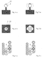
- eine stark vereinfachte, schaltplanartige Prinzipdarstellung einer Schaltvorrichtung,
- Fig. 2 bis 5
- jeweils einem Schalthebel in a) einer Seitenansicht und b) einer Draufsicht mit c) der zugehörigen Anzeige bei unterschiedlichen Schaltstellungen,
- Fig. 6 bis 9
- jeweils den Schalthebel a) in einer Draufsicht mit Betätigungsrichtung und b) mit zugehöriger Anzeige.
- Entsprechend Fig. 1 umfasst eine erfindungsgemäße Schaltvorrichtung 1 einen Schalthebel 2, der in einer Schaltgassenanordnung 3 verstellbar ist, sowie eine Anzeige 4 und eine Getriebesteuerung 5. Die Schaltvorrichtung 1 dient zum Betätigen eines automatisierten oder automatischen Getriebes 6, vorzugsweise eines Kraftfahrzeugs.
- Die Schaltgassenanordnung 3, die auch als reelle Schaltgassenkonfiguration bezeichnet werden kann, umfasst eine erste Schaltgasse 7 und eine die erste Schaltgasse 7 kreuzende zweite Schaltgasse 8. Die erste Schaltgasse 7 ist im Einbauzustand vorzugsweise parallel zur Fahrzeuglängsrichtung orientiert und wird daher im folgenden auch als Längsgasse 7 bezeichnet. Im Unterschied dazu ist die zweite Schaltgasse 8 vorzugsweise quer zur Fahrzeuglängsrichtung orientiert und wird daher im folgenden auch als Quergasse 8 bezeichnet. Längsgasse 7 und Quergasse 8 stehen vorzugsweise senkrecht aufeinander. Die reelle Schaltgassenkonfiguration 3 ist so ausgestaltet, dass sie für den Schalthebel 2 eine stabile Ausgangsstellung 9 sowie mehrere labile Schaltstellungen 10 bis 13 bereitstellt. Die labilen Schaltstellungen 10 bis 13 sind unmittelbar benachbart zur stabilen Ausgangsstellung 9 angeordnet und charakterisieren sich dadurch, dass der aus der stabilen Ausgangsstellung 9 in eine der labilen Schaltstellungen 10 bis 13 ausgelenkte Schalthebel 2 automatisch in die Ausgangsstellung 9 zurückkehrt. Hierzu ist die Schaltvorrichtung 1 mit entsprechenden Rückstellmitteln versehen. Die Ausgangsstellung 9 ist bezüglich der Schaltstellungen 10 bis 13 zentral angeordnet. In der gezeigten, bevorzugten Einbausituation muss der Schalthebel 2 aus der Ausgangsstellung 9 zum Überführen in die Schaltstellung 10 nach vorn, in die Schaltstellung 11 nach hinten, in die Schaltstellung 12 nach links und in die Schaltstellung 13 nach rechts ausgelenkt werden. Somit liegen die Links-Schaltstellung 12 und die Rechts-Schaltstellung 13 auf der Quergasse 8 beiderseits der Ausgangsstellung 9 während die Vorne-Schaltstellung 10 und die Hinten-Schaltstellung 11 in der Längsgasse 7 beiderseits der Ausgangsstellung 9 angeordnet sind.
- Des weiteren umfasst die Schaltgassenanordnung 3 eine als Ruhestellung 14 bezeichnete weitere stabile Schaltstellung, in welche der Schalthebel 2 aus der Ausgangsstellung 9 überführbar ist. Die stabile Ruhestellung 14 ist ebenfalls in der Längsgasse 7 angeordnet und zwar endseitig. Da keine weitere Quergasse vorhanden ist, ist der Schalthebel 2 aus der Ruhestellung 14 nur in einer Richtung, nämlich in Richtung zur Ausgangsstellung 9 herausführbar. In Fig. 1 sind stabile Schaltstellungen durch Doppelkreise symbolisiert, während labile Schaltstellungen durch Einfachkreise dargestellt sind.
- Die Getriebesteuerung 5 ordnet der stabilen Ausgangsstellung 9 und den labilen Schaltstellungen 10 bis 13 Automatikschaltstufen und/oder Gänge des Getriebes 6 zu. Hierzu ist eine durch einen Doppelpfeil angedeutete elektronische Wirkverbindung 15 zwischen der Getriebesteuerung 5 und der Schaltgassenanordnung 3 vorgesehen. Des weiteren ist die Getriebesteuerung 5 durch eine elektronische Wirkverbindung 16 mit der Anzeige 4 verbunden. Die Anzeige 4 dient zum Visualisieren des aktuell eingelegten Gangs und/oder der aktuell aktivierten Automatikschaltstufe. Des weiteren dient die Anzeige 4 hier zur Visualisierung aller möglichen Gänge und Automatikschaltstufen. Beispielsweise umfasst das Getriebe 6 als Automatikschaltstufen eine Vorwärts-Schaltstufe D, eine Leerlauf-Schaltstufe N und eine Rückwärts-Schaltstufe R. Des weiteren ist hier eine Manual-Schaltstufe M vorgesehen, in der durch Auslenken des Schalthebels 2 in dazu benachbarte Schaltstellungen zum Herunterschalten, so genannte Runterschaltstellung, gekennzeichnet durch ein Minus-Zeichen (-), und zum Hochschalten, so genannte Hochschaltstellung, gekennzeichnet durch ein Plus-Zeichen (+), die einzelnen Gänge (1) bis (6) des Getriebes 6 anwählbar sind.
- Die vorgenannten Schaltstellungen, Getriebegänge und Automatikschaltstufen sind über die Getriebesteuerung 5 elektronisch der Ausgangsstellung 9 und den dazu benachbarten vier labilen Schaltstellungen 10 bis 13 zugeordnet. Die Getriebesteuerung 5 ist dabei auf übliche Weise, z.B. über eine durch einen Doppelpfeil angedeutete elektronische Wirkverbindung 23 mit dem Getriebe 6 gekoppelt.
- Des weiteren umfasst das Getriebe 6 eine Parkschaltstufe P, in der eine Parksperre des Getriebes 6 aktiviert ist. Diese Park-Schaltstufe P ist der stabilen Ruhestellung 14 zugeordnet. Entsprechend einer bevorzugten Ausführungsform der vorliegenden Erfindung ist die Park-Schaltstufe P der Ruhestellung 14 nicht elektronisch über die Getriebesteuerung 5, sondern mechanisch zugeordnet. Eine entsprechende mechanische Wirkverbindung 17 zwischen der Ruhestellung 14 und dem Getriebe 6 ist in Fig. 1 durch einen Doppelpfeil symbolisiert. Diese mechanische Wirkverbindung 17 ist beispielsweise durch einen Seilzug realisiert. Somit kann die Parksperre des Getriebes 6 beim Überführen des Schalthebels 2 in die Ruhestellung 14 mechanisch durch eine Zwangskopplung zwischen Getriebe 6 und Schalthebel 2 aktiviert werden, wobei die Verstellbewegung des Schalthebels 2 den dazu erforderlichen Antrieb liefert.
- Die Schaltvorrichtung 1 umfasst vorzugsweise genau zwei stabile Schaltstellungen, nämlich die Ausgangsstellung 9 und die Ruhestellung 14, sowie genau vier labile Schalthebelstellungen 10 bis 13. Über diese insgesamt 6 Schaltstellungen 9 bis 14 sind alle Gänge und Automatikschaltstufen des Getriebes 6 auswählbar.
- Um die Bedienung der Schaltvorrichtung 1 für den Anwender zu vereinfachen, simuliert die Getriebesteuerung 5 eine virtuelle Schaltgassenkonfiguration 18, die dem Anwender über die Anzeige 4 visualisiert wird. Die virtuelle Schaltgassenkonfiguration 18 umfasst zwei parallele Schaltgassen, nämlich eine Automatik-Schaltgasse 19 zum Auswählen der Automatikschaltstufen und eine Tipp-Schaltgasse 20 zum Auswählen der Gänge. Des weiteren ist eine Verbindungsgasse 21 vorgesehen, die sich quer zu den beiden Schaltgassen 19, 20 erstreckt und diese miteinander verbindet. In der Automatikschaltgasse 19 werden mehrere virtuelle stabile Schaltgassenpositionen simuliert, denen jeweils eine der Automatik-Schaltstufen, hier die Vorwärts-Schaltstufe D, die Rückwärts-Schaltstufe R und dazwischen die Leerlauf-Schaltstufe N, zugeordnet ist. Im Unterschied dazu umfasst die Tipp-Schaltgasse 20 nur eine virtuelle stabile Schaltgassenposition, der die Manual-Schaltstufe M zugeordnet ist. Jedoch umfasst die Tipp-Schaltgasse 20 beiderseits der Manual-Schaltstufe M zusätzlich zwei virtuelle labile Schaltgassenpositionen, denen die Hochschaltstellung (+) und die Runterschaltstellung (-) zugeordnet sind. Die Verbindungsgasse 21 ist hier so angeordnet, dass sie virtuell die Manual-Schaltstufe M mit der Vorwärts-Schaltstufe D verbindet. Des weiteren visualisiert die Anzeige 4 die reelle stabile Ruhestellung 14, der die Park-Schaltstufe P zugeordnet ist. Außerdem visualisiert die Anzeige 4 vorzugsweise die schaltbaren Vorwärtsgänge des Getriebes 6. In den anderen Fig. sind die jeweils aktive Automatikschaltstufe und der jeweils eingelegte Getriebegang durch einen den jeweiligen Doppelkreis ausfüllenden Ring symbolisiert.
- Mit Bezug auf die Fig. 2 bis 5 wird im folgenden das Überführen des Schalthebels 2 von der Ruhestellung 14 zur Ausgangsstellung 9 und umgekehrt näher erläutert.
- In den Fig. 2a bis 2c befindet sich der Schalthebel 2 in der Ruheposition 14. Dieser ist die Park-Schaltstufe P zugeordnet, was an der Anzeige 4 durch eine entsprechende Hervorhebung signalisiert ist. Bei der hier gezeigten bevorzugten Ausführungsform ist die Schaltvorrichtung 1 zusätzlich mit einer Sicherungstaste 22 ausgestattet, die bei der hier gezeigten Ausführungsform in den Schalthebel 2 integriert ist bzw. an diesem ausgebildet oder angeordnet ist. Im Zustand der Fig. 2a bis 2c ist die Sicherungstaste 22 unbetätigt. Die Sicherungstaste 22 ist so ausgestaltet, dass in ihrem unbetätigten Zustand der in die Ruhestellung 14 verstellte Schalthebel 2 in der Ruhestellung 14 gesichert ist und somit unverstellbar ist. Die Park-Schaltstufe P ist somit effektiv gesichert.
- In den Fig. 3a bis 3c ist die Sicherungstaste 22 betätigt, z.B. durch Niederdrücken. In ihrem betätigten Zustand gibt die Sicherungstaste 22 den Schalthebel 2 frei, so dass dieser aus der Ruhestellung 14 herausgeführt werden kann. Durch Betätigen der Sicherungstaste 22 bei in die Ruhestellung 14 verstelltem Schalthebel 2 bleibt jedoch die Park-Schaltstufe P und somit die Parksperre des Getriebes 6 aktiv.
- Die Fig. 4a bis 4c zeigen den in die Ausgangsstellung 9 verstellten Schalthebel 2 bei betätigter Sicherungstaste 22. Die Sicherungstaste 22 ist dabei so ausgestaltet, dass sie im betätigen Zustand den in die Ausgangsstellung 9 verstellten Schalthebel 2 in der Ausgangsstellung 9 sichert, und zwar so, dass er nicht in die benachbarten labilen Schaltstellungen 10 bis 13 überführbar ist. Bei betätigter Sicherungstaste 22 lässt sich der Schalthebel 2 ausschließlich zwischen der Ruhestellung 14 und der Ausgangsstellung 9 verstellen. Wie Fig. 4c entnehmbar ist, aktiviert die Getriebesteuerung 5 beim Überführen des Schalthebels 2 von der Ruhestellung 14 in die Ausgangsstellung 9 automatisch die Leerlauf-Schaltstufe N.
- Erst wenn die Sicherungstaste 22 nach dem Überführen des Schalthebels 2 in die Ausgangsstellung 9 entsprechend den Fig. 5a bis 5c unbetätigt ist, lässt sich der Schalthebel 2 von seiner Ausgangsstellung 9 in die labilen Schaltstellungen 10 bis 13 auslenken, jedoch nicht mehr in die stabile Ruhestellung 14.
- Für die Überführung des Schalthebels 2 aus der Ruhestellung 14 in die Ausgangsstellung 9 kann eine weitere Sicherung in Form einer hier nicht näher gezeigten Riegelvorrichtung vorgesehen sein. Diese verriegelt den Schalthebel 2 in der Ruhestellung 14, solange ein Zündschlüssel eines mit dem Getriebe 6 ausgestatteten Fahrzeugs in ein Zündschloss eingesteckt ist und/oder solange sich der Zündschlüssel im Zündschloss in einer Abzugsposition befindet und/oder solange eine Betriebsbremse des Fahrzeugs unbetätigt ist. Mit anderen Worten, der Schalthebel 2 kann z.B. nur dann aus der Ruhestellung 14 in die Ausgangsstellung 9 überführt werden, wenn ein Zündschlüssel im Zündschloss angeordnet ist, dabei aus der Abzugsposition herausgedreht ist und wenn der Fahrzeugführer die Betriebsbremse betätigt.
- Ist der Schalthebel 2 erfolgreich von der Ruhestellung 14 in die Ausgangsstellung 9 überführt, ist die Leerlauf-Schaltstufe N aktiviert. Der Schalthebel 2 kann nun nach vorn, hinten, links und rechts in die entsprechenden labilen Schaltstellungen 10 bis 13 ausgelenkt werden. Die Getriebesteuerung 5 ordnet die Auslenkung des Schalthebels 2 in Abhängigkeit der Bewegungsrichtung dieser Schalthebelauslenkung einer Bewegung des Schalthebels 2 in der virtuellen Schaltgassenkonfiguration 18 in der entsprechenden Richtung zu. Im folgenden wird anhand der Fig. 6 bis 9 mit mehreren Beispielen die Funktionsweise der Schaltvorrichtung 1 näher erläutert.
- Im Ausgangszustand befindet sich der Schalthebel 2 in der reellen Ausgangsstellung 9 und innerhalb der virtuellen Schaltgassenkonfiguration 18 in der Leerlauf-Schaltstufe N. Entsprechend der virtuellen Automatik-Schaltgasse 19 führt nur ein Auslenken des Schalthebels 2 in die Vorne-Schaltstellung 10 und in die Hinten-Schaltstellung 11 zu einem Schaltvorgang, während Auslenkungen nach links und rechts ignoriert werden. Um kritische Situationen für das Getriebe 6 zu vermeiden, kann eine zusätzliche Sicherung vorgesehen sein, dergestalt, dass die Getriebesteuerung 5 auch ein Auslenken nach vorn und ein Auslenken nach hinten ignoriert, solange die Leerlauf-Schaltstufe N aktiviert ist und die Betriebsbremse des Fahrzeugs unbetätigt ist. Das bedeutet, dass bei aktiver Leerlauf-Schaltstufe N ein Umschalten in eine andere Automatikschaltstufe durch Auslenken des Schalthebels 2 in eine der labilen Schaltstellungen 10 bis 13 nur dann möglich ist, wenn die Betriebsbremse des Fahrzeugs betätigt ist.
- Entsprechend Fig. 6a wird der Schalthebel 2 nach vorn in die labile Vorne-Schaltstellung 10 ausgelenkt. In der Folge bewirkt die Getriebesteuerung 5 eine Aktivierung der Rückwärts-Schaltstufe R. In der virtuellen Automatik-Schaltgasse 19 wird dadurch der Schalthebel 2 entsprechend verstellt, was gemäß Fig. 6b der Anzeige 4 entnehmbar ist.
- Wird jedoch der Schalthebel 2 entsprechend Fig. 7a in die Hinten-Schaltstellung 11 ausgelenkt, bewirkt die Getriebesteuerung 5 ausgehend von der Leerlauf-Schaltstufe N ein Umschalten in die Vorwärts-Schaltstufe D. Der aktive Schaltzustand bzw. die aktuelle Position des Schalthebels 2 innerhalb der virtuellen Schaltgassenkonfiguration 18 ist gemäß Fig. 7b wieder der Anzeige 4 zu entnehmen. Durch die Aktivierung der Vorwärts-Schaltstufe D ausgehend von der Leerlauf-Schaltstufe N wird automatisch der erste Getriebegang eingelegt, was ebenfalls in der Anzeige 4 erkennbar ist.
- Befindet sich der Schalthebel 2 in der virtuellen Automatik-Schaltgasse 19 in der Vorwärts-Schaltstufe D lässt er sich entsprechend Fig. 8a durch eine Auslenkung in die Links-Schaltstellung 12 über die virtuelle Verbindungsgasse 11 in die virtuelle Tipp-Gasse 20 überführen, und zwar dort in die Manual-Schaltstufe M, was entsprechend Fig. 8b wieder der Anzeige 4 entnehmbar ist. Mit dem Aktivieren der Manual-Schaltstufe M wird dabei der aktuell eingelegte Getriebegang nicht verändert. Im Beispiel bleibt somit der erste Gang eingelegt.
- Entsprechen Fig. 9a kann nun durch Vortippen und Zurücktippen in die labile Vorne-Schaltstellung 10 bzw. die labile Hinten-Schaltstellung 11 der Schalthebel 2 innerhalb der virtuellen Tipp-Gasse 20 ausgelenkt werden. Damit geht ein schrittweises Hochschalten und Runterschalten der Getriebegänge einher. In dem in Fig. 9b gezeigten Beispiel ist der 5. Gang eingelegt.
- Bemerkenswert ist, dass der Schalthebel 2 trotz unterschiedlicher virtueller stabiler Schaltstellungen innerhalb der virtuellen Schaltgassen 19, 20 reell stets nur die stabile Ausgangsstellung 9 einnimmt.
Claims (10)
- Schaltvorrichtung für ein automatisiertes oder automatisches Getriebe (6), insbesondere eines Kraftfahrzeugs,- mit einem Schalthebel (2) zum Auswählen von Automatikschaltstufen und Gängen des Getriebes (6), der aus einer stabilen Ausgangsstellung (9) in mehrere unmittelbar benachbarte labile Schaltstellungen (10, 11, 12, 13) zum Auswählen der Automatikschaltstufen und der Gänge überführbar ist, aus denen er selbsttätig in die Ausgangsstellung (9) zurückkehrt,- mit einer Anzeige (4) zum Visualisieren des aktuell eingelegten Gangs und/oder der aktuell aktivierten Automatikschaltstufe,dadurch gekennzeichnet, dass der Schalthebel (2) außerdem aus der Ausgangsstellung (9) in eine stabile Ruhestellung (14) überführbar ist, aus der er ausschließlich in Richtung der Ausgangsstellung (9) herausführbar ist.
- Schaltvorrichtung nach Anspruch 1, dadurch gekennzeichnet, dass ausschließlich zwei stabile Schaltstellungen vorgesehen sind, nämlich die Ausgangsstellung (9) und die Ruhestellung (14).
- Schaltvorrichtung nach Anspruch 1 oder 2, dadurch gekennzeichnet,- dass eine Sicherungstaste (22) vorgesehen ist, die im unbetätigten Zustand den in die Ruhestellung (14) verstellten Schalthebel (2) in der Ruhestellung (14) sichert und nur im betätigten Zustand ein Herausführen des Schalthebels (2) aus der Ruhestellung (14) zulässt, und/oder- dass die Sicherungstaste (22) im betätigten Zustand den in die Ausgangsstellung (9) verstellten Schalthebel (2) in der Ausgangsstellung (9) sichert, derart, dass er nur im unbetätigten Zustand in die benachbarten labilen Schaltstellungen (10, 11, 12, 13) verstellbar ist, und/oder- dass die Sicherungstaste (22) nur im betätigten Zustand ein Überführen des Schalthebels (2) von der Ausgangsstellung (9) in die Ruhestellung (14) zulässt, und/oder- dass die Sicherungstaste (22) am Schalthebel (2) ausgebildet ist oder in diesen integriert ist.
- Schaltvorrichtung nach einem der Ansprüche 1 bis 3, dadurch gekennzeichnet,- dass genau vier labile Schaltstellungen (10, 11, 12, 13) benachbart zur Ausgangsstellung (9) angeordnet sind, und/oder- dass zwei zur Ausgangsstellung (9) benachbarte labile Schaltstellungen (10, 11) in einer ersten Schaltgasse (7) oder Längsgasse (7) angeordnet sind, und/oder- dass zwei zur Ausgangsstellung (9) benachbarte labile Schaltstellungen (12, 13) in einer zweiten Schaltgasse (8) oder Quergasse (8) angeordnet sind, und/oder- dass die erste Schaltgasse (7) oder Längsgasse (7) senkrecht zur zweiten Schaltgasse (8) oder Quergasse (8) angeordnet ist, und/oder- dass die Ruhestellung (14) an einem Ende der ersten Schaltgasse (7) oder Längsgasse (7) angeordnet ist.
- Schaltvorrichtung nach einem der Ansprüche 1 bis 4, dadurch gekennzeichnet,- dass bei in die Ruhestellung (14) verstelltem Schalthebel (2) eine Parksperre des Getriebes (6) aktiviert ist, und/oder- dass die Parksperre beim Überführen des Schalthebels (2) in die Ruhestellung (14) mechanisch durch die Verstellbewegung des Schalthebels (2) aktiviert wird.
- Schaltvorrichtung nach einem der Ansprüche 1 bis 5, dadurch gekennzeichnet,- dass eine Getriebesteuerung (5) vorgesehen ist, die den labilen Schaltstellungen (10, 11, 12, 13) die Automatikschaltstufen und die Gänge zuordnet und die den jeweils ausgewählten Gang oder die jeweils ausgewählte Automatikschaltstufe elektronisch aktiviert, und/oder- dass die Getriebesteuerung (5) eine virtuelle Schaltgassenkonfiguration (18) simuliert, die eine Automatik-Schaltgasse (19) zum Auswählen der Automatikschaltstufen und eine dazu parallele Tipp-Schaltgasse (20) zum Auswählen der Gänge sowie eine quer zu den Schaltgassen (19, 20) verlaufende Verbindungsgasse (21) aufweist, und/oder- dass die Automatik-Schaltgasse (19) mehrere virtuelle stabile Schaltgassenpositionen aufweist, denen jeweils eine der Automatikschaltstufen zugeordnet ist, und/oder- dass die virtuellen stabilen Schaltgassenpositionen der Automatik-Schaltgasse (19) eine Vorwärts-Schaltstufe (D), eine Rückwärts-Schaltstufe (R) und eine, vorzugsweise dazwischen angeordnete, Leerlauf-Schaltstufe (N) umfassen, und/oder- dass die Tipp-Schaltgasse (20) eine virtuelle stabile Schaltgassenposition, der eine Manual-Schaltstufe (M) zugeordnet ist, und zwei dazu direkt benachbarte virtuelle labile Schaltgassenpositionen aufweist, denen eine Hochschaltstellung und eine Herunterschaltstellung zum Umschalten der Gänge zugeordnet sind, und/oder- dass die Verbindungsgasse (21) zwei virtuelle stabile Schaltgassenpositionen aufweist, denen jeweils eine der Automatikschaltstufen zugeordnet ist, und/oder- dass die virtuellen stabilen Schaltgassenpositionen der Verbindungsgasse die Manual-Schaltstufe (M) der Tipp-Schaltgasse (20) und die Vorwärts-Schaltstufe (D) der Automatik-Schaltgasse (19) sind.
- Schaltvorrichtung nach Anspruch 6, dadurch gekennzeichnet,- dass die Anzeige (4) die virtuelle Schaltgassenkonfiguration (18) visualisiert, und/oder- dass das Überführen des Schalthebels (2) in einer Bewegungsrichtung aus der stabilen Ausgangsstellung (9) in eine der labilen Schaltstellungen (10, 11, 12, 13) ein Umschalten des Schalthebels (2) aus dessen aktueller virtueller Schaltgassenposition in die in derselben Bewegungsrichtung direkt benachbarte virtuelle Schaltgassenposition bewirkt.
- Schaltvorrichtung nach einem der Ansprüche 1 bis 7, dadurch gekennzeichnet, dass eine Riegelvorrichtung vorgesehen ist, die den in die Ruhestellung (14) verstellten Schalthebel (2) in der Ruhestellung (14) verriegelt, solange wenigstens eine der folgenden Bedingungen erfüllt ist:- ein Zündschlüssel eines mit dem Getriebe (6) ausgestatteten Fahrzeugs befindet sich nicht im Zündschloss;- der Zündschlüssel befindet sich im Zündschloss in einer Abzugsposition;- eine Betriebsbremse des Fahrzeugs ist unbetätigt.
- Schaltvorrichtung nach einem der Ansprüche 1 bis 8, dadurch gekennzeichnet, dass eine Getriebesteuerung (5), die den labilen Schaltstellungen (10, 11, 12, 13) Automatikschaltstufen zuordnet, so ausgestaltet ist, dass sie Auslenkungen des Schalthebels (2) in eine dieser labilen Schaltstufen ignoriert, wenn die aktuell aktivierte Automatikschaltstufe eine Leerlauf-Schaltstufe N ist und wenn eine Betriebsbremse eines mit dem Getriebe (6) ausgestatteten Fahrzeugs unbetätigt ist.
- Schaltvorrichtung nach einem der Ansprüche 1 bis 9, dadurch gekennzeichnet, dass eine Getriebesteuerung (5), die den labilen Schaltstellungen (10, 11, 12, 13) Automatikschaltstufen zuordnet, so ausgestaltet ist, dass sie bei aktuell aktivierter Leerlauf-Schaltstufe N die Auslenkungen des Schalthebels (2) in eine dieser labilen Schaltstufen nur dann berücksichtigt, wenn die Auslenkung in eine Vorne-Schaltstellung (10) oder in eine Hinten-Schaltstellung (11) erfolgt.
Applications Claiming Priority (1)
| Application Number | Priority Date | Filing Date | Title |
|---|---|---|---|
| DE102005062298A DE102005062298A1 (de) | 2005-12-24 | 2005-12-24 | Schaltvorrichtung für ein Getriebe |
Publications (3)
| Publication Number | Publication Date |
|---|---|
| EP1801463A2 true EP1801463A2 (de) | 2007-06-27 |
| EP1801463A3 EP1801463A3 (de) | 2008-06-18 |
| EP1801463B1 EP1801463B1 (de) | 2013-10-23 |
Family
ID=37890529
Family Applications (1)
| Application Number | Title | Priority Date | Filing Date |
|---|---|---|---|
| EP06024481.1A Expired - Fee Related EP1801463B1 (de) | 2005-12-24 | 2006-11-25 | Schaltvorrichtung für ein Getriebe |
Country Status (4)
| Country | Link |
|---|---|
| US (1) | US7878087B2 (de) |
| EP (1) | EP1801463B1 (de) |
| JP (1) | JP4747083B2 (de) |
| DE (1) | DE102005062298A1 (de) |
Cited By (2)
| Publication number | Priority date | Publication date | Assignee | Title |
|---|---|---|---|---|
| CN102815212A (zh) * | 2011-06-09 | 2012-12-12 | 现代自动车株式会社 | 点火控制类型的汽车杆设备 |
| EP2868948A1 (de) * | 2013-10-29 | 2015-05-06 | Volvo Car Corporation | Verfahren zum Schalten von Gängen, und Schaltanordnung |
Families Citing this family (13)
| Publication number | Priority date | Publication date | Assignee | Title |
|---|---|---|---|---|
| DE102005062296B3 (de) * | 2005-12-24 | 2007-08-09 | Dr.Ing.H.C. F. Porsche Ag | Getriebeschaltvorrichtung |
| DE102007007667A1 (de) * | 2007-02-13 | 2008-08-14 | Leopold Kostal Gmbh & Co. Kg | Elektrische Schalteinrichtung für ein Kraftfahrzeug |
| DE102007037750B4 (de) * | 2007-08-10 | 2013-03-14 | Bayerische Motoren Werke Aktiengesellschaft | Wählhebel für ein Kraftfahrzeug |
| DE102007047120B4 (de) * | 2007-10-02 | 2013-01-10 | Audi Ag | Schalteinheit für ein insbesondere elektronisch geschaltetes Getriebe eines Kraftfahrzeugs |
| DE102008049935A1 (de) | 2008-10-02 | 2010-04-08 | Dura Automotive Systems Einbeck Gmbh | Verfahren zur Schaltbetätigung eines Automatikgetriebes oder automatischen Schaltgetriebes eines Fahrzeugs und Wählbetätigungsvorrichtung |
| GB0905843D0 (en) * | 2009-04-03 | 2009-05-20 | Bentley Motors Ltd | Selector |
| DE112011100277T5 (de) * | 2010-01-19 | 2012-11-08 | Honda Motor Co., Ltd. | Schaltvorrichtung |
| US20130220055A1 (en) * | 2012-02-28 | 2013-08-29 | Nissan North America, Inc. | Multifunctional integrated shifter |
| US9476501B2 (en) * | 2013-05-21 | 2016-10-25 | GM Global Technology Operations LLC | Gear shifter |
| US9115803B2 (en) * | 2013-08-28 | 2015-08-25 | Ford Global Technologies, Llc | Methods and systems for operating a transmission |
| DE102015102586A1 (de) * | 2015-02-24 | 2016-08-25 | Küster Holding GmbH | Schalteinheit für ein Getriebe eines Kraftfahrzeuges |
| KR102584369B1 (ko) * | 2018-12-11 | 2023-10-04 | 에스엘 주식회사 | 차량용 변속 장치 |
| CN112344007B (zh) * | 2019-08-08 | 2022-04-26 | 广州汽车集团股份有限公司 | 一种单稳态电子换挡机构的换挡方法 |
Citations (4)
| Publication number | Priority date | Publication date | Assignee | Title |
|---|---|---|---|---|
| DE19714495A1 (de) | 1997-04-08 | 1998-10-15 | Bayerische Motoren Werke Ag | Wähleinrichtung mit einer Anzeigeeinrichtung |
| DE10112698A1 (de) | 2001-03-16 | 2002-09-19 | Daimler Chrysler Ag | Schaltvorrichtung für ein Kraftfahrzeuggetriebe |
| DE10206985A1 (de) | 2002-02-20 | 2003-08-21 | Bayerische Motoren Werke Ag | Getriebeschalteinrichtung |
| DE202004004151U1 (de) | 2004-03-17 | 2004-06-03 | Zf Friedrichshafen Ag | Schaltvorrichtung für automatisierte oder automatische Getriebe |
Family Cites Families (17)
| Publication number | Priority date | Publication date | Assignee | Title |
|---|---|---|---|---|
| DE3929268A1 (de) * | 1989-09-02 | 1991-03-07 | Bayerische Motoren Werke Ag | Kraftfahrzeuggetriebe |
| JPH10100723A (ja) * | 1996-09-27 | 1998-04-21 | Toyota Motor Corp | 自動変速機の表示装置 |
| DE19714459C2 (de) | 1997-04-08 | 2001-11-29 | Framatome Connectors Int | Steckverbinder mit einer Gehäuseverriegelung |
| DE19737296C2 (de) * | 1997-08-27 | 1999-11-18 | Daimler Chrysler Ag | Selbsttätige Schaltvorrichtung eines Gangwechselgetriebes mit einem Handwählorgan |
| JP3962968B2 (ja) * | 1999-04-12 | 2007-08-22 | スズキ株式会社 | 自動車用変速機のパーキング装置 |
| JP2001280463A (ja) * | 2000-03-31 | 2001-10-10 | Isuzu Motors Ltd | 車両の自動変速装置 |
| JP2002139143A (ja) * | 2000-11-06 | 2002-05-17 | Tokai Rika Co Ltd | 車両用変速機制御装置 |
| DE10208387B4 (de) * | 2001-02-28 | 2014-01-30 | Kabushiki Kaisha Tokai Rika Denki Seisakusho | Gerät zum elektrischen Steuern eines Getriebes eines Fahrzeuges |
| DE60238731D1 (de) * | 2001-03-02 | 2011-02-10 | Toyota Motor Co Ltd | Schaltvorrichtung für ein Kraftfahrzeug |
| JP2002276782A (ja) * | 2001-03-16 | 2002-09-25 | Fuji Heavy Ind Ltd | 自動変速機の入力装置 |
| JP4590772B2 (ja) * | 2001-04-12 | 2010-12-01 | トヨタ自動車株式会社 | シフト制御装置 |
| DE10156091A1 (de) * | 2001-10-05 | 2003-07-10 | Zf Lemfoerder Metallwaren Ag | Signalgeber zum Einstellen der Betriebszustände einer selbsttätigen Schaltvorrichtung |
| JP3996380B2 (ja) * | 2001-11-27 | 2007-10-24 | 株式会社東海理化電機製作所 | シフトロック装置 |
| DE10223854A1 (de) * | 2002-05-28 | 2003-12-11 | Zf Lemfoerder Metallwaren Ag | Optische Anzeigevorrichtung einer Wählhebelanordnung |
| DE10326118B4 (de) * | 2003-06-06 | 2005-04-14 | ZF Lemförder Metallwaren AG | Schaltvorrichtung zur mechanisch kopplungsfreien Übertragung von Schaltbefehlen an ein automatisches Kraftfahrzeuggetriebe |
| JP2005119394A (ja) * | 2003-10-15 | 2005-05-12 | Atsumi Tec:Kk | 車両用自動変速操作装置 |
| JP4789758B2 (ja) * | 2005-11-25 | 2011-10-12 | 日産自動車株式会社 | Atセレクタカバー |
-
2005
- 2005-12-24 DE DE102005062298A patent/DE102005062298A1/de not_active Ceased
-
2006
- 2006-11-25 EP EP06024481.1A patent/EP1801463B1/de not_active Expired - Fee Related
- 2006-12-13 JP JP2006335764A patent/JP4747083B2/ja not_active Expired - Fee Related
- 2006-12-26 US US11/645,838 patent/US7878087B2/en not_active Expired - Fee Related
Patent Citations (4)
| Publication number | Priority date | Publication date | Assignee | Title |
|---|---|---|---|---|
| DE19714495A1 (de) | 1997-04-08 | 1998-10-15 | Bayerische Motoren Werke Ag | Wähleinrichtung mit einer Anzeigeeinrichtung |
| DE10112698A1 (de) | 2001-03-16 | 2002-09-19 | Daimler Chrysler Ag | Schaltvorrichtung für ein Kraftfahrzeuggetriebe |
| DE10206985A1 (de) | 2002-02-20 | 2003-08-21 | Bayerische Motoren Werke Ag | Getriebeschalteinrichtung |
| DE202004004151U1 (de) | 2004-03-17 | 2004-06-03 | Zf Friedrichshafen Ag | Schaltvorrichtung für automatisierte oder automatische Getriebe |
Cited By (2)
| Publication number | Priority date | Publication date | Assignee | Title |
|---|---|---|---|---|
| CN102815212A (zh) * | 2011-06-09 | 2012-12-12 | 现代自动车株式会社 | 点火控制类型的汽车杆设备 |
| EP2868948A1 (de) * | 2013-10-29 | 2015-05-06 | Volvo Car Corporation | Verfahren zum Schalten von Gängen, und Schaltanordnung |
Also Published As
| Publication number | Publication date |
|---|---|
| US20070144294A1 (en) | 2007-06-28 |
| JP2007168771A (ja) | 2007-07-05 |
| EP1801463B1 (de) | 2013-10-23 |
| JP4747083B2 (ja) | 2011-08-10 |
| DE102005062298A1 (de) | 2007-06-28 |
| EP1801463A3 (de) | 2008-06-18 |
| US7878087B2 (en) | 2011-02-01 |
Similar Documents
| Publication | Publication Date | Title |
|---|---|---|
| EP1801463B1 (de) | Schaltvorrichtung für ein Getriebe | |
| DE10206985B4 (de) | Getriebeschalteinrichtung | |
| DE102005062296B3 (de) | Getriebeschaltvorrichtung | |
| EP2049818B1 (de) | Schaltvorrichtung für ein automatisiertes oder automatisches getriebe | |
| DE102007010052A1 (de) | Steuer-/Regelvorrichtung für ein Automatikgetriebe | |
| DE4332265C1 (de) | Anordnung zum Steuern des Gangwechsels eines selbsttätig schaltenden Gangwechselgetriebes eines Kraftfahrzeuges | |
| WO2004090388A1 (de) | Mehrstufiges schaltgetriebe für eine brennkraftmaschine | |
| WO2008074375A1 (de) | Schaltungsbedienelement für ein getriebe eines kraftfahrzeugs mit elektronisch gesteuerter schaltung | |
| EP1549866B1 (de) | Fahrstufen-eingabeeinheit | |
| DE19850685A1 (de) | Wähleinrichtung für ein automatisches Getriebe eines Kraftfahrzeugs | |
| DE102006039955B4 (de) | Rückwärts- und Parksperrvorrichtung in einem Getriebesteuermechanismus | |
| EP1432934A1 (de) | Signalgeber zum einstellen der betriebszustände einer selbsttätigen schaltvorrichtung | |
| DE4308637A1 (de) | Schaltvorrichtung für ein Handschaltgetriebe eines Kraftfahrzeuges | |
| DE102007047120A1 (de) | Schalteinheit für ein insbesondere elektronisch geschaltetes Getriebe eines Kraftfahrzeugs | |
| DE102005048875B4 (de) | Schalteinheit für ein elektronisch geschaltetes Getriebe eines Kraftfahrzeugs | |
| DE10315643B3 (de) | Shift by wire-Schaltung mit P-Position | |
| DE3439161A1 (de) | Getriebesteuerung | |
| DE3337930C2 (de) | Wählschalter in einer Schaltsteuerung für Automatgetriebe | |
| DE3742600C2 (de) | ||
| DE19849076A1 (de) | Wähleinrichtung für ein automatisch geschaltetes Getriebe eines Kraftfahrzeugs | |
| EP1380773B1 (de) | Vorrichtung und Verfahren zur Steuerung eines automatisierten Schaltgetriebes eines Kraftfahrzeuges | |
| DE102004026106B4 (de) | Schaltvorrichtung eines Automatikgetriebes für Fahrzeuge | |
| DE102005025888A1 (de) | Schalteinheit für elektronisch geschaltetes Getriebe in Kraftfahrzeugen | |
| EP0025198A2 (de) | Schaltvorrichtung für Zahnräderwechselgetriebe in Gruppenbauart für Kraftfahrzeuge | |
| WO1997021944A1 (de) | Elektrohydraulische steuereinrichtung für lastschaltgetriebe |
Legal Events
| Date | Code | Title | Description |
|---|---|---|---|
| PUAI | Public reference made under article 153(3) epc to a published international application that has entered the european phase |
Free format text: ORIGINAL CODE: 0009012 |
|
| AK | Designated contracting states |
Kind code of ref document: A2 Designated state(s): AT BE BG CH CY CZ DE DK EE ES FI FR GB GR HU IE IS IT LI LT LU LV MC NL PL PT RO SE SI SK TR |
|
| AX | Request for extension of the european patent |
Extension state: AL BA HR MK YU |
|
| RAP1 | Party data changed (applicant data changed or rights of an application transferred) |
Owner name: DR. ING. H.C. F. PORSCHE AKTIENGESELLSCHAFT |
|
| PUAL | Search report despatched |
Free format text: ORIGINAL CODE: 0009013 |
|
| AK | Designated contracting states |
Kind code of ref document: A3 Designated state(s): AT BE BG CH CY CZ DE DK EE ES FI FR GB GR HU IE IS IT LI LT LU LV MC NL PL PT RO SE SI SK TR |
|
| AX | Request for extension of the european patent |
Extension state: AL BA HR MK RS |
|
| RIC1 | Information provided on ipc code assigned before grant |
Ipc: F16H 59/10 20060101ALI20080513BHEP Ipc: F16H 59/02 20060101AFI20070404BHEP |
|
| RAP1 | Party data changed (applicant data changed or rights of an application transferred) |
Owner name: DR. ING. H.C. F. PORSCHE AKTIENGESELLSCHAFT |
|
| 17P | Request for examination filed |
Effective date: 20081218 |
|
| AKX | Designation fees paid |
Designated state(s): DE FR GB IT |
|
| 17Q | First examination report despatched |
Effective date: 20090129 |
|
| RAP1 | Party data changed (applicant data changed or rights of an application transferred) |
Owner name: DR. ING. H.C. F. PORSCHE AG |
|
| GRAP | Despatch of communication of intention to grant a patent |
Free format text: ORIGINAL CODE: EPIDOSNIGR1 |
|
| INTG | Intention to grant announced |
Effective date: 20130730 |
|
| GRAS | Grant fee paid |
Free format text: ORIGINAL CODE: EPIDOSNIGR3 |
|
| GRAA | (expected) grant |
Free format text: ORIGINAL CODE: 0009210 |
|
| AK | Designated contracting states |
Kind code of ref document: B1 Designated state(s): DE FR GB IT |
|
| REG | Reference to a national code |
Ref country code: GB Ref legal event code: FG4D Free format text: NOT ENGLISH |
|
| REG | Reference to a national code |
Ref country code: DE Ref legal event code: R096 Ref document number: 502006013296 Country of ref document: DE Effective date: 20131219 |
|
| REG | Reference to a national code |
Ref country code: DE Ref legal event code: R097 Ref document number: 502006013296 Country of ref document: DE |
|
| REG | Reference to a national code |
Ref country code: FR Ref legal event code: ST Effective date: 20140731 |
|
| PG25 | Lapsed in a contracting state [announced via postgrant information from national office to epo] |
Ref country code: IT Free format text: LAPSE BECAUSE OF FAILURE TO SUBMIT A TRANSLATION OF THE DESCRIPTION OR TO PAY THE FEE WITHIN THE PRESCRIBED TIME-LIMIT Effective date: 20131023 |
|
| PLBE | No opposition filed within time limit |
Free format text: ORIGINAL CODE: 0009261 |
|
| STAA | Information on the status of an ep patent application or granted ep patent |
Free format text: STATUS: NO OPPOSITION FILED WITHIN TIME LIMIT |
|
| GBPC | Gb: european patent ceased through non-payment of renewal fee |
Effective date: 20140123 |
|
| 26N | No opposition filed |
Effective date: 20140724 |
|
| REG | Reference to a national code |
Ref country code: DE Ref legal event code: R097 Ref document number: 502006013296 Country of ref document: DE Effective date: 20140724 |
|
| PG25 | Lapsed in a contracting state [announced via postgrant information from national office to epo] |
Ref country code: GB Free format text: LAPSE BECAUSE OF NON-PAYMENT OF DUE FEES Effective date: 20140123 Ref country code: FR Free format text: LAPSE BECAUSE OF NON-PAYMENT OF DUE FEES Effective date: 20131223 |
|
| PGFP | Annual fee paid to national office [announced via postgrant information from national office to epo] |
Ref country code: DE Payment date: 20191024 Year of fee payment: 14 |
|
| REG | Reference to a national code |
Ref country code: DE Ref legal event code: R119 Ref document number: 502006013296 Country of ref document: DE |
|
| PG25 | Lapsed in a contracting state [announced via postgrant information from national office to epo] |
Ref country code: DE Free format text: LAPSE BECAUSE OF NON-PAYMENT OF DUE FEES Effective date: 20210601 |