EP1549866B1 - Fahrstufen-eingabeeinheit - Google Patents
Fahrstufen-eingabeeinheit Download PDFInfo
- Publication number
- EP1549866B1 EP1549866B1 EP03807737A EP03807737A EP1549866B1 EP 1549866 B1 EP1549866 B1 EP 1549866B1 EP 03807737 A EP03807737 A EP 03807737A EP 03807737 A EP03807737 A EP 03807737A EP 1549866 B1 EP1549866 B1 EP 1549866B1
- Authority
- EP
- European Patent Office
- Prior art keywords
- input unit
- selector lever
- stage input
- manual gear
- manual
- Prior art date
- Legal status (The legal status is an assumption and is not a legal conclusion. Google has not performed a legal analysis and makes no representation as to the accuracy of the status listed.)
- Expired - Lifetime
Links
- 230000004913 activation Effects 0.000 claims description 3
- 230000005540 biological transmission Effects 0.000 description 14
- 238000010079 rubber tapping Methods 0.000 description 6
- 230000000903 blocking effect Effects 0.000 description 3
- 230000007935 neutral effect Effects 0.000 description 3
- 239000000523 sample Substances 0.000 description 3
- 230000006835 compression Effects 0.000 description 2
- 238000007906 compression Methods 0.000 description 2
- 238000004891 communication Methods 0.000 description 1
- 238000010276 construction Methods 0.000 description 1
- 230000001419 dependent effect Effects 0.000 description 1
- 230000000694 effects Effects 0.000 description 1
- 230000008030 elimination Effects 0.000 description 1
- 238000003379 elimination reaction Methods 0.000 description 1
- 238000005516 engineering process Methods 0.000 description 1
- 230000003287 optical effect Effects 0.000 description 1
- 230000000007 visual effect Effects 0.000 description 1
Images


Classifications
-
- F—MECHANICAL ENGINEERING; LIGHTING; HEATING; WEAPONS; BLASTING
- F16—ENGINEERING ELEMENTS AND UNITS; GENERAL MEASURES FOR PRODUCING AND MAINTAINING EFFECTIVE FUNCTIONING OF MACHINES OR INSTALLATIONS; THERMAL INSULATION IN GENERAL
- F16H—GEARING
- F16H59/00—Control inputs to control units of change-speed- or reversing-gearings for conveying rotary motion
- F16H59/02—Selector apparatus
- F16H59/08—Range selector apparatus
- F16H59/10—Range selector apparatus comprising levers
- F16H59/105—Range selector apparatus comprising levers consisting of electrical switches or sensors
-
- F—MECHANICAL ENGINEERING; LIGHTING; HEATING; WEAPONS; BLASTING
- F16—ENGINEERING ELEMENTS AND UNITS; GENERAL MEASURES FOR PRODUCING AND MAINTAINING EFFECTIVE FUNCTIONING OF MACHINES OR INSTALLATIONS; THERMAL INSULATION IN GENERAL
- F16H—GEARING
- F16H61/00—Control functions within control units of change-speed- or reversing-gearings for conveying rotary motion ; Control of exclusively fluid gearing, friction gearing, gearings with endless flexible members or other particular types of gearing
- F16H61/22—Locking of the control input devices
-
- F—MECHANICAL ENGINEERING; LIGHTING; HEATING; WEAPONS; BLASTING
- F16—ENGINEERING ELEMENTS AND UNITS; GENERAL MEASURES FOR PRODUCING AND MAINTAINING EFFECTIVE FUNCTIONING OF MACHINES OR INSTALLATIONS; THERMAL INSULATION IN GENERAL
- F16H—GEARING
- F16H61/00—Control functions within control units of change-speed- or reversing-gearings for conveying rotary motion ; Control of exclusively fluid gearing, friction gearing, gearings with endless flexible members or other particular types of gearing
- F16H61/12—Detecting malfunction or potential malfunction, e.g. fail safe ; Circumventing or fixing failures
-
- Y—GENERAL TAGGING OF NEW TECHNOLOGICAL DEVELOPMENTS; GENERAL TAGGING OF CROSS-SECTIONAL TECHNOLOGIES SPANNING OVER SEVERAL SECTIONS OF THE IPC; TECHNICAL SUBJECTS COVERED BY FORMER USPC CROSS-REFERENCE ART COLLECTIONS [XRACs] AND DIGESTS
- Y10—TECHNICAL SUBJECTS COVERED BY FORMER USPC
- Y10T—TECHNICAL SUBJECTS COVERED BY FORMER US CLASSIFICATION
- Y10T74/00—Machine element or mechanism
- Y10T74/20—Control lever and linkage systems
- Y10T74/20012—Multiple controlled elements
- Y10T74/20018—Transmission control
-
- Y—GENERAL TAGGING OF NEW TECHNOLOGICAL DEVELOPMENTS; GENERAL TAGGING OF CROSS-SECTIONAL TECHNOLOGIES SPANNING OVER SEVERAL SECTIONS OF THE IPC; TECHNICAL SUBJECTS COVERED BY FORMER USPC CROSS-REFERENCE ART COLLECTIONS [XRACs] AND DIGESTS
- Y10—TECHNICAL SUBJECTS COVERED BY FORMER USPC
- Y10T—TECHNICAL SUBJECTS COVERED BY FORMER US CLASSIFICATION
- Y10T74/00—Machine element or mechanism
- Y10T74/20—Control lever and linkage systems
- Y10T74/20012—Multiple controlled elements
- Y10T74/20018—Transmission control
- Y10T74/2003—Electrical actuator
-
- Y—GENERAL TAGGING OF NEW TECHNOLOGICAL DEVELOPMENTS; GENERAL TAGGING OF CROSS-SECTIONAL TECHNOLOGIES SPANNING OVER SEVERAL SECTIONS OF THE IPC; TECHNICAL SUBJECTS COVERED BY FORMER USPC CROSS-REFERENCE ART COLLECTIONS [XRACs] AND DIGESTS
- Y10—TECHNICAL SUBJECTS COVERED BY FORMER USPC
- Y10T—TECHNICAL SUBJECTS COVERED BY FORMER US CLASSIFICATION
- Y10T74/00—Machine element or mechanism
- Y10T74/20—Control lever and linkage systems
- Y10T74/20012—Multiple controlled elements
- Y10T74/20018—Transmission control
- Y10T74/20085—Restriction of shift, gear selection, or gear engagement
- Y10T74/20104—Shift element interlock
Definitions
- the present invention relates to the locking of actuators specifically in one of a speed input unit for an automatic transmission in vehicles. More particularly, the invention relates to a manual speed input unit having a plurality of actuators, such as a selector lever and a push button.
- Shift-by-wire circuits have the fundamental problem that in gearbox failure or in the event of failure of the vehicle electronics (failure of the transmission control unit, failure of the circuit electronics, line interruption, Failure of the power supply, etc.) the transmission can no longer execute the commands of the driver or the transmission can no longer be configured.
- a guaranteed not overlooked feedback represents the locking or setting of the corresponding actuator.
- the driver immediately recognizes that the desired transmission setting can not be executed or implemented.
- the object of the present invention is therefore to provide a multi-component manual input unit with regard to the operating elements a simultaneous blocking of all components under certain conditions can be performed.
- a manual speed input unit for selecting speed levels with a first actuating element for selecting at least one driving stage and at least one further actuating element for setting additional functions.
- a pawl which can be moved by means of an actuator is provided, by means of which the first and the at least one further actuating element can be locked and unlocked at the same time.
- the speed input unit according to the invention is designed such that differ in their operation at least two actuators.
- the first actuating element can represent a selector lever and the second actuating element a button.
- the pawl is inventively arranged so that in a first position of the pawl all actuators are locked and therefore can not be operated and in a second position of the pawl all actuators are unlocked and can be operated.
- the first position by mechanical spring force and the second position occupied by electrical activation of the actuator are advantageousously, the first position by mechanical spring force and the second position occupied by electrical activation of the actuator.
- the selector lever is a monostable selector lever, which returns to its original position after manual deflection in at least one direction.
- the button returns to its original position after its operation.
- the actuator is preferably an electromagnet.
- the speed input unit comprises a plurality of actuators, wherein by a corresponding arrangement relative to the pawl, a first part of these actuators locked and at the same time the other part can be unlocked.
- FIG. 1 shows a perspective view obliquely from above on an embodiment of a manual speed input unit 1 according to the invention.
- the speed input unit 1 has two actuating elements in the form of a selector lever 2 and a pushbutton 3.
- the lower end of the selector lever (snap-10) is pressed by a built-in lower part of the lever shaft compression spring 9 against a wedge-shaped latching contour 11, so that after a deflection of the selector lever to the selector lever pivot point 12 again the original middle Position of the lever is taken.
- This behavior of the selector lever 2 is called monostable Behavior referred to as the selector lever always occupies a preferred middle position.
- the driving position P (PARK), the driver according to the embodiment of Figure 1, regardless of the selector lever adjustment by pressing the button 3 select. After pressing the button 3, this also returns to its original position.
- the inventive manual gear input unit of the above embodiment is shown from the side.
- the selector lever 2 is in the undeflected state, the button 3 is not activated.
- the shaft of the button 3 has a protuberance 15 in the amount of a sensor 5.
- the sensor 5 has a contact lever on which in the non-activated state ( Figure 1) of the button 3 is opened.
- the protuberance 15 closes the contact lever of the sensor 5 (FIG. 2).
- the contact closure causes the corresponding electrical command to the transmission in this case to take the P (PARK).
- a pawl 6 is provided which is pivotally mounted at one end 7.
- the pawl 6 takes an engagement of the pawl 6 in the two actuators (selector lever 2 and button 3) so that a locking of these actuators 2.3 takes place.
- the engagement is realized by recesses of the pawl 6 at the level of the probe shaft and the undeflected selector shaft.
- the shaft of the respective actuating element may have a recess into which the pawl is pivoted.
- the pivoting of the pawl 6 is effected on the one hand by an actuator 8 (e.g., an electromagnet) on the other hand by a return spring. It makes sense, therefore, the pawl 6 monostable and indeed in such a way that in the de-energized state of the manual speed input unit 1, the return spring causes a mutual engagement of the pawl 6 with the actuators 2.3 and thus a lock.
- the releasing position of the pawl 6 is preferably given by the energized position of the actuator 8, so that in case of failure of the power supply (power supply) solely by the purely mechanical restoring force of the return spring, the actuators are locked 2.3.
- the pawl 6 is arranged in the figure 4 so that the recesses 14 the Shaft of the respective actuating element comprise, so that on the one hand, the selector lever 2 is no longer deflected from its initial position and on the other hand, the button 3 can not be pressed.
- Figure 4 describes the situation in case of elimination of the electrical power supply, in which by the bias of a return spring, the engagement of the pawl is effected in the actuators and their blocking. A tilting or tapping the selector lever 2 and a depression of the button 3 is no longer possible in this state, whereby the driver is made aware that the control of the transmission and thus a speed step selection is no longer possible.
- FIG. 5 shows the situation with existing electrical energy.
- the pawl is deflected against the force of the return spring and the shafts of both actuators released, so that a tilting or tapping of the selector lever 2 and a push of the button 3 is possible.
- Both actuators 2, 3 are activated, i. the selector lever 2 can be tilted and the button 3 can be pressed, the protuberance 15 closes the contact of the probe sensor 5.
- FIG. 4 only the selector lever 2 is tilted and the pushbutton 3 is shown pressed down, although in practice the simultaneous activation is unlikely.
- Figures 1 to 5 show only one possible embodiment of the invention.
- the selector lever 3 for example, by another lane or by other selector lever
- all driving levels P, R, N, D are selected while another actuator or even more actuators (such as the button) is not necessarily for the operation of the Gear must serve.
- the individual actuators can be locked or released in a corresponding grouping simultaneously.
- all speed steps can also be selected by several buttons (one button each for P, R, N and D) that are disabled or released under certain conditions.
Landscapes
- Engineering & Computer Science (AREA)
- General Engineering & Computer Science (AREA)
- Mechanical Engineering (AREA)
- Arrangement Or Mounting Of Control Devices For Change-Speed Gearing (AREA)
- Gear-Shifting Mechanisms (AREA)
Description
- Die vorliegende Erfindung bezieht sich auf das Sperren bzw. Freigeben von Betätigungselementen speziell bei einem einer Fahrstufen-Eingabeeinheit für ein Automatik-Getriebe in Fahrzeugen. Die Erfindung betrifft insbesondere eine manuelle Fahrstufen-Eingabeeinheit mit mehreren Betätigungselementen, wie beispielsweise einem Wählhebel und einem Taster.
- Im Fahrzeugbau werden Automatik-Getriebe eingesetzt die verschiedene Fahrstufen zur Verfügung stellen. Die Fahrstufen - abgekürzt mit P,R,N und D (P=Park, R=Reverse, N=Neutral, D=Drive) - können vom Fahrer mit einem Wählhebel bzw. einem Taster angewählt werden. Bei modernen Fahrzeugen wird die vom Fahrer ausgewählte Fahrstufe über eine entsprechende Elektronik abgetastet und elektronisch an die Getriebeelektronik übertragen, die das Getriebe entsprechend verstellt. Dabei entfällt die früher übliche mechanische Verbindung zwischen dem Getriebe und der manuellen Fahrstufen-Eingabeeinheit (Wählhebel und/oder Taster). Dieses Konzept wird allgemein als "Shift-by-wire-Schaltung" bezeichnet.
- Shift-by-wire-Schaltungen haben das grundsätzliche Problem, dass bei Getriebenotlauf bzw. bei Ausfall der Kfz-Elektronik (Ausfall des Getriebesteuergerätes, Ausfall der Schaltungselektronik, Leitungsunterbrechung, Ausfall der Spannungsversorgung, usw.) das Getriebe die Befehle des Fahrers nicht mehr ausführen kann bzw. das Getriebe nicht mehr konfiguriert werden kann.
- Aus EP 1062 439 B1 ist bei einer solchen Situation eine optische, akustische oder haptische (taktile) Rückmeldung an den Fahrer bekannt. Eine haptische Rückmeldung wird beispielsweise durch eine Erhöhung oder Reduzierung der Betätigungskraft dargestellt. Derartige haptische aber auch optische und akustische Rückmeldungen werden vom Fahrer nicht immer sicher erkannt, im schlimmsten Fall werden sie sogar ignoriert.
- Eine garantiert nicht übersehbare Rückmeldung stellt das Sperren bzw. Festsetzen des entsprechenden Betätigungselementes dar. Dadurch erkennt der Fahrer sofort, dass die gewünschte Getriebe-Einstellung nicht ausgeführt bzw. umgesetzt werden kann.
- Eine derartige Sperrung eines einzigen Betätigungselementes für konventionelle Schaltungen (Seilzug- oder Stangenverbindung zum Getriebe) ist bekannt. Insbesondere bei herkömmlichen Automatikschaltungen werden unter gewissen Bedingungen die Fahrstufen PARK und NEUTRAL gesperrt.
- Bei Shift-by-wire-Schaltungen besteht die Möglichkeit die Anwahl der verschiedenen Fahrstufen (P, R, N, D) auf zwei oder mehrere Betätigungselemente (beispielsweise Wählhebel und Taster) aufzuteilen bzw. in die manuelle Fahrstufen-Eingabeeinheit weitere Betätigungselemente, die nicht zur Bedienung des Getriebes dienen sondern andere Funktionen haben, aufzunehmen.
- Aus der gattungsgemäßen US-A-4 324 151 ist eine manuelle Eingabe-Einheit bekannt, wobei durch eine manuelle Sperre zwei Bedienungselemente gleichzeitig gesperrt werden können.
- Aufgabe der vorliegenden Erfindung ist es daher eine hinsichtlich der Bedienelemente mehrkomponentige manuelle Eingabe-Einheit bereitzustellen in der eine gleichzeitige Sperrung aller Komponenten unter gewissen Randbedingungen durchgeführt werden kann.
- Die oben genannte Aufgabe wird durch eine manuelle Fahrstufen-Eingabeeinheit gemäß den Merkmalen des Anspruchs 1 gelöst. Die abhängigen Ansprüche bilden den zentralen Gedanken der Erfindung in besonders vorteilhafter Weise weiter.
- Beansprucht wird gemäß der vorliegenden Erfindung eine manuelle Fahrstufen-Eingabeeinheit zum Auswählen von Fahrstufen mit einem ersten Betätigungselement zum Auswählen zumindest einer Fahrstufe und zumindest einem weiteren Betätigungselement zur Einstellung weiterer Funktionen. Erfindungsgemäß ist dabei eine mittels eines Aktuators bewegbare Sperrklinke vorgesehen, durch welche das erste und das zumindest eine weitere Betätigungselement gleichzeitig verriegelt und entriegelt werden können.
- Insbesondere ist die erfindungsgemäße Fahrstufen-Eingabeeinheit derart ausgebildet, dass sich mindestens zwei Betätigungselemente in ihrer Funktionsweise unterscheiden.
- Dabei kann das erste Betätigungselement einen Wählhebel und das zweite Betätigungselement einen Taster darstellen.
- Die Sperrklinke ist erfindungsgemäß so angeordnet, dass in einer ersten Position der Sperrklinke alle Betätigungselemente verriegelt sind und daher nicht betätigt werden können und in einer zweiten Position der Sperrklinke alle Betätigungselemente entriegelt sind und betätigt werden können.
- Vorteilhafterweise wird die erste Position durch mechanische Federkraft und die zweite Position durch elektrische Aktivierung des Aktuators eingenommen.
- In einer bevorzugten Ausführungsform der Erfindung stellt der Wählhebel einen monostabilen Wählhebel dar, der nach dem manuellen Auslenken in zumindest eine Richtung wieder in seine Ausgangslage zurückkehrt.
- Ebenso kehrt der Taster nach seiner Betätigung wieder in seine Ausgangslage zurück.
- Im Sinne einer einfachen Bedienweise der Fahrstufen-Eingabeeinheit stellt der Aktuator vorzugsweise einen Elektromagneten dar.
- In einer weiteren Ausführungsform der Erfindung weist die Fahrstufen-Eingabeeinheit eine Mehrzahl von Betätigungselementen auf, wobei durch eine entsprechende Anordnung relativ zur Sperrklinke ein erster Teil dieser Betätigungselemente verriegelt und gleichzeitig der andere Teil entriegelt werden kann.
- Weitere Merkmale, Eigenschaften und Vorteile der vorliegenden Erfindung werden nunmehr anhand von Ausführungsbeispielen und unter Bezugnahme auf die begleitenden Figuren der Zeichnungen erläutert.
- Figur 1
- zeigt eine perspektivische Sicht von schräg oben vorne auf eine erfindungsgemäße manuelle Fahrstufen-Eingabeeinheit mit einem in einem Gehäuse teilweise integrierten Wählhebel und einem Taster als Betätigungselemente,
- Figur 2
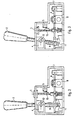
- zeigt schematisch einen Schnitt durch die wesentlichsten Komponenten der erfindungsgemäßen manuellen Fahrstufen-Eingabeeinheit im verriegelten Zustand der beiden Betätigungselemente,
- Figur 3
- zeigt schematisch einen Schnitt durch die wesentlichsten Komponenten der erfindungsgemäßen manuellen Fahrstufen-Eingabeeinheit im entriegelten und betätigten Zustand beider Betätigungselemente,
- Figur 4
- zeigt eine perspektivische Sicht von schräg oben hinten auf eine erfindungsgemäße manuelle Fahrstufen-Eingabeeinheit mit einem Wählhebel und einem Taster als Betätigungselemente ohne Gehäuse im verriegelten Zustand,
- Figur 5
- zeigt eine perspektivische Sicht von schräg oben hinten auf eine erfindungsgemäße manuelle Fahrstufen-Eingabeeinheit mit einem Wählhebel und einem Taster als Betätigungselemente ohne Gehäuse im entriegelten Zustand.
- Figur 1 zeigt eine perspektivische Sicht von schräg oben vorne auf ein Ausführungsbeispiel einer erfindungsgemäßen manuellen Fahrstufen-Eingabeeinheit 1. In diesem Ausführungsbeispiel weist die Fahrstufen-Eingabeeinheit 1 zwei Betätigungselemente in Form eines Wählhebels 2 sowie eines Tasters 3 auf.
- Das untere Ende des Wählhebels (Einrast-Pin 10) wird durch eine im unteren Teil des Hebel-Schaftes integrierte Druckfeder 9 gegen eine keilförmige Einrast-Kontur 11 gedrückt, so dass nach einer Auslenkung des Wählhebels um den Wählhebel-Drehpunkt 12 wieder die ursprünglich mittlere Position des Hebels eingenommen wird. Dieses Verhalten des Wählhebels 2 wird als monostabiles Verhalten bezeichnet, da der Wählhebel stets eine bevorzugte mittlere Position einnimmt. Durch Antippen und damit Auslenken des Wählhebels in der in das Gehäuse oder dessen Abdeckung eingeschnittenen Gasse 13 nach vorne oder nach hinten ist es dem Fahrer möglich eine andere Fahrstufe zu wählen, zum Beispiel falls die vorher ausgewählte Fahrstufe N (NEUTRAL) war, kann R (REVERSE) durch Antippen nach vorne sowie D (DRIVE) durch Antippen nach hinten gewählt werden. Falls die zuletzt ausgewählte Fahrstufe D war, kann durch einmaliges Antippen nach vorne die Fahrstufe N und durch zweimaliges Antippen die Fahrstufe R gewählt werden. Durch eine spezielle Aufnahme-Sensorik 4 für den Wählhebel wird die zuletzt gewählte Fahrstufe abgetastet und elektronisch an die Getriebeelektronik weitergegeben.
- Die Fahrstufe P (PARK) kann der Fahrer gemäß dem Ausführungsbeispiel der Figur 1 unabhängig von der Wählhebeleinstellung durch Drücken des Tasters 3 anwählen. Nach dem Betätigen des Tasters 3 kehrt dieser ebenfalls wieder in seine Ausgangsstellung zurück.
- In Figur 2 ist die erfindungsgemäße manuelle Fahrstufen-Eingabeeinheit des obigen Ausführungsbeispieles von der Seite dargestellt. Der Wählhebel 2 befindet sich im nichtausgelenkten Zustand, der Taster 3 ist nicht aktiviert. Der Schaft des Tasters 3 hat eine Protuberanz 15 in Höhe eines Sensors 5. Der Sensor 5 weist einen Kontakthebel auf der im nicht-aktivierten Zustand (Figur 1) des Tasters 3 geöffnet ist. Bei Betätigung des Tasters schließt die Protuberanz 15 den Kontakthebel des Sensors 5 (Figur 2). Der Kontaktschluss bewirkt den entsprechenden elektrischen Befehl an das Getriebe in diesem Fall die Fahrstufe P (PARK) einzunehmen.
- Um beispielsweise bei Ausfall der elektrischen Kommunikation dem Fahrer eine sichere nicht zu ignorierende Rückmeldung zu geben, dass die Betätigung der manuellen Fahrstufen-Eingabeeinheit keinerlei Wirkung mehr hat ist in der manuellen Fahrstufen-Eingabeeinheit eine Sperrklinke 6 vorgesehen die an einem Ende 7 schwenkbar gelagert ist. Durch Schwenken der Sperrklinke 6 erfolgt ein Eingriff der Sperrklinke 6 in die beiden Betätigungselemente (Wählhebel 2 und Taster 3) so dass eine Arretierung dieser Betätigungselemente 2,3 erfolgt. In diesem Ausführungsbeispiel wird der Eingriff durch Aussparungen der Sperrklinke 6 auf Höhe des Tasterschaftes sowie des nichtausgelenkten Wählhebelschaftes realisiert. Genauso kann aber auch der Schaft des jeweiligen Betätigungselementes eine Aussparung aufweisen in die die Sperrklinke eingeschwenkt wird. Durch die Arretierung ist eine Sperrung der beiden Betätigungselemente derart gegeben, dass der Wählhebel 2 nicht mehr bewegt und der Taster 3 nicht mehr gedrückt werden kann.
- Das Schwenken der Sperrklinke 6 wird einerseits durch einen Aktuator 8 (z.B. ein Elektromagnet) andererseits durch eine Rückstellfeder bewirkt. Sinnvollerweise ist also auch die Sperrklinke 6 monostabil und zwar in der Weise, dass im stromlosen Zustand der manuellen Fahrstufen-Eingabeeinheit 1 die Rückstellfeder ein gegenseitiges Eingreifen der Sperrklinke 6 mit den Betätigungselementen 2,3 und damit eine Arretierung bewirkt. Die freigebende Position der Sperrklinke 6 ist vorzugsweise durch die bestromte Stellung des Aktuators 8 gegeben, so dass bei Ausfall der Energiezufuhr (Spannungsversorgung) allein durch die rein mechanische Rückstellkraft der Rückstellfeder die Betätigungselemente 2,3 gesperrt werden.
- In den Figuren 4 und 5 ist der erfindungsgemäße Mechanismus zur Arretierung der beiden unterschiedlichen Betätigungselement (Wählhebel 2 und Taster 3) deutlich dargestellt:
- Die Sperrklinke 6 ist in der Figur 4 so angeordnet, dass die Aussparungen 14 den Schaft der jeweiligen Betätigungselementes umfassen, so dass einerseits der Wählhebel 2 aus seiner Ausgangsstellung nicht mehr ausgelenkt und andererseits der Taster 3 nicht mehr gedrückt werden kann. Figur 4 beschreibt die Situation bei Wegfall der elektrischen Energiezufuhr, bei der durch die Vorspannung einer Rückstellfeder der Eingriff der Sperrklinke in die Betätigungselemente und deren Sperrung bewirkt wird. Ein Kippen bzw. Antippen des Wählhebels 2 und ein Niederdrücken des Tasters 3 ist in diesem Zustand nicht mehr möglich, wodurch dem Fahrer bewusst gemacht wird, dass die Kontrolle über das Getriebe und damit eine Fahrstufenauswahl nicht mehr möglich ist.
- In Figur 5 ist die Situation bei vorhandener elektrischer Energie dargestellt. Durch Bestromung des Aktuators 8 wird die Sperrklinke gegen die Kraft der Rückstellfeder ausgelenkt und die Schäfte beider Betätigungselemente freigegeben, so dass ein Kippen bzw. Antippen des Wählhebels 2 sowie ein Drücken des Tasters 3 möglich ist. Beide Betätigungselemente 2,3 sind aktiviert, d.h. der Wählhebel 2 kann verkippt werden und der Taster 3 kann gedrückt werden, wobei die Protuberanz 15 den Kontakt des Taster-Sensors 5 schließt. Nur zur Verdeutlichung sind in Figur 4 sowohl der Wählhebel 2 verkippt als auch der Taster 3 gedrückt dargestellt, obwohl in der Praxis die gleichzeitige Aktivierung eher unwahrscheinlich ist.
- Die Figuren 1 bis 5 zeigen nur eine mögliche Ausgestaltung der Erfindung. Genauso können durch eine andere Ausführung des Wählhebels 3 (beispielsweise durch eine weitere Gasse oder durch weitere Wählhebel) alle Fahrstufen P,R,N,D angewählt werden während ein weiteres Betätigungselement oder überhaupt weitere Betätigungselemente (wie beispielsweise der Taster) nicht unbedingt zur Bedienung des Getriebes dienen muss. Dabei können die einzelnen Betätigungselemente in entsprechender Gruppierung gleichzeitig gesperrt oder freigegeben werden. Möglich wäre z.B. eine Ausführung mit zwei Wählhebeln, wobei mit dem einen Hebel die Fahrstufen P,R,N,D eingelegt werden können und mit dem anderen Wählhebel die Gänge manuell geschaltet werden können (z.B. schrittweises Schalten der Gänge 1 bis 5). Genauso können aber auch sämtliche Fahrstufen durch mehrere Taster angewählt werden (je eine Taste für P,R,N und D) die unter gewissen Bedingungen gesperrt oder freigegeben werden.
-
- 1
- Manuelle Fahrstufen-Eingabeeinheit
- 2
- Wählhebel
- 3
- Taster
- 4
- Sensorik für Wählhebel
- 5
- Sensor für Taster
- 6
- Sperrklinke
- 7
- Lagerstelle Sperrklinke
- 8
- Aktuator (z.B. Elektromagnet)
- 9
- Druckfeder
- 10
- Einrast-Pin
- 11
- Einrast-Kontur
- 12
- Wählhebel-Drehpunkt
- 13
- Gasse
- 14
- Aussparung in der Sperrklinke
- 15
- Protuberanz am Tasterschaft
Claims (9)
- Manuelle Fahrstufen-Eingabeeinheit (1) zum Auswählen von Fahrstufen mit einem ersten Betätigungselement (2) zum Auswählen zumindest einer Fahrstufe und zumindest einem weiteren Betätigungselement (3) zur Einstellung weiterer Funktionen, wobei
eine bewegbare Sperrklinke (6) vorgesehen ist, durch welche das erste und das zumindest eine weitere Betätigungselement (2,3) gleichzeitig verriegelt und entriegelt werden könne,
dadurch gekennzeichnet, daß
die Sperrklinke durch einen Aktuator bewegt wird. - Manuelle Fahrstufen-Eingabeeinheit (1) nach Anspruch 1,
dadurch gekennzeichnet, dass
sich mindestens zwei Betätigungselemente in ihrer Funktionsweise unterscheiden. - Manuelle Fahrstufen-Eingabeeinheit (1) nach Anspruch 2,
dadurch gekennzeichnet, dass
die Einheit (1) aus zwei unterschiedlichen Betätigungselementen besteht, wobei das erste Betätigungselement einen Wählhebel (2) und das zweite Betätigungselement einen Taster (3) darstellt. - Manuelle Fahrstufen-Eingabeeinheit (1) nach Anspruch 1, 2 oder 3,
dadurch gekennzeichnet, dass
die Sperrklinke (6) so angeordnet ist, dass in einer ersten Position der Sperrklinke (6) alle Betätigungselemente (2, 3) verriegelt sind und daher nicht betätigt werden können und in einer zweiten Position der Sperrklinke (6) alle Betätigungselemente (2, 3) entriegelt sind und betätigt werden können. - Manuelle Fahrstufen-Eingabeeinheit (1) nach Anspruch 4,
dadurch gekennzeichnet, dass
die erste Position durch mechanische Federkraft
und die zweite Position durch elektrische Aktivierung des Aktuators (8) eingenommen wird. - Manuelle Fahrstufen-Eingabeeinheit (1) nach Anspruch 5,
dadurch gekennzeichnet, dass
der Wählhebel ein monostabiler Wählhebel ist, der nach dem manuellen Auslenken in zumindest eine Richtung wieder in seine Ausgangslage zurückkehrt. - Manuelle Fahrstufen-Eingabeeinheit (1) nach einem der Ansprüche 5 bis 6,
dadurch gekennzeichnet, dass
der Taster nach seiner Betätigung wieder in seine Ausgangslage zurückkehrt. - Manuelle Fahrstufen-Eingabeeinheit (1) nach einem der Ansprüche 1 bis 7,
dadurch gekennzeichnet, dass
der Aktuator (8) ein Elektromagnet ist. - Manuelle Fahrstufen-Eingabeeinheit (1) nach einem der Ansprüche 1 bis 4,
dadurch gekennzeichnet, dass
die Eingabeeinheit (1) eine Mehrzahl von Betätigungselementen aufweist, wobei durch eine entsprechende Anordnung relativ zur Sperrklinke ein erster Teil dieser Betätigungselemente verriegelt und gleichzeitig der andere Teil entriegelt werden kann.
Applications Claiming Priority (3)
| Application Number | Priority Date | Filing Date | Title |
|---|---|---|---|
| DE10247068 | 2002-10-09 | ||
| DE10247068A DE10247068A1 (de) | 2002-10-09 | 2002-10-09 | Fahrstufen-Eingabeeinheit |
| PCT/DE2003/003382 WO2004033939A1 (de) | 2002-10-09 | 2003-10-09 | Fahrstufen-eingabeeinheit |
Publications (2)
| Publication Number | Publication Date |
|---|---|
| EP1549866A1 EP1549866A1 (de) | 2005-07-06 |
| EP1549866B1 true EP1549866B1 (de) | 2006-12-06 |
Family
ID=32038387
Family Applications (1)
| Application Number | Title | Priority Date | Filing Date |
|---|---|---|---|
| EP03807737A Expired - Lifetime EP1549866B1 (de) | 2002-10-09 | 2003-10-09 | Fahrstufen-eingabeeinheit |
Country Status (6)
| Country | Link |
|---|---|
| US (1) | US6993994B2 (de) |
| EP (1) | EP1549866B1 (de) |
| JP (1) | JP4365320B2 (de) |
| DE (2) | DE10247068A1 (de) |
| ES (1) | ES2275137T3 (de) |
| WO (1) | WO2004033939A1 (de) |
Families Citing this family (19)
| Publication number | Priority date | Publication date | Assignee | Title |
|---|---|---|---|---|
| DE10315643B3 (de) * | 2003-04-04 | 2004-10-28 | ZF Lemförder Metallwaren AG | Shift by wire-Schaltung mit P-Position |
| DE102005023969B4 (de) * | 2005-05-20 | 2007-12-06 | HDO Druckguß- und Oberflächentechnik GmbH | Schaltvorrichtung für ein Getriebe eines Kraftfahrzeugs |
| DE102005043288A1 (de) | 2005-09-09 | 2007-03-15 | Leopold Kostal Gmbh & Co. Kg | Elektrische Schalteinrichtung für ein Kraftfahrzeug |
| DE102005044254A1 (de) * | 2005-09-15 | 2007-03-29 | Zf Friedrichshafen Ag | Betätigungseinrichtung mit Zusatzschaltelement |
| JP4650355B2 (ja) * | 2006-06-29 | 2011-03-16 | トヨタ自動車株式会社 | 車両のシフト制御装置 |
| US7814444B2 (en) * | 2007-04-13 | 2010-10-12 | Synopsys, Inc. | Scan compression circuit and method of design therefor |
| GB2452054B (en) | 2007-08-23 | 2012-04-18 | Jaguar Cars | A shift-by-wire selector control system for a motor vehicle transmission |
| DE102008015874A1 (de) * | 2008-03-26 | 2009-10-01 | Lemförder Electronic GmbH | Betätigungseinrichtung mit Haptikemulation |
| WO2009155896A1 (de) * | 2008-06-23 | 2009-12-30 | Luk Lamellen Und Kupplungsbau Beteiligungs Kg | Verfahren zur steuerung eines antriebsstrangs |
| JP5167185B2 (ja) * | 2009-03-31 | 2013-03-21 | 富士機工株式会社 | シフトレバー装置 |
| DE102009039113B4 (de) | 2009-08-27 | 2013-09-05 | Audi Ag | Schalteinheit für ein insbesondere elektronisch geschaltetes Getriebe eines Kraftfahrzeugs |
| DE102012112144A1 (de) * | 2012-12-12 | 2014-06-26 | Dr. Ing. H.C. F. Porsche Aktiengesellschaft | Betätigungsanordnung für ein automatisches Kraftfahrzeuggetriebe und für eine Bremsvorrichtung sowie Verfahren zum Betätigen einer derartigen Betätigungsanordnung |
| US9476501B2 (en) * | 2013-05-21 | 2016-10-25 | GM Global Technology Operations LLC | Gear shifter |
| JP6060941B2 (ja) * | 2014-07-03 | 2017-01-18 | マツダ株式会社 | 車両用シフト装置 |
| JP6060942B2 (ja) * | 2014-07-03 | 2017-01-18 | マツダ株式会社 | 車両用シフト装置 |
| JP6060943B2 (ja) * | 2014-07-03 | 2017-01-18 | マツダ株式会社 | 車両用シフト装置 |
| KR102425035B1 (ko) * | 2017-10-16 | 2022-07-27 | 현대자동차주식회사 | 변속 장치를 포함하는 차량 |
| DE102018202729B3 (de) * | 2018-02-23 | 2019-08-01 | Audi Ag | Sperrvorrichtung für einen Wählhebel eines Kraftfahrzeugs mit automatischem Getriebe |
| RU205855U1 (ru) * | 2021-02-09 | 2021-08-11 | Общество с ограниченной ответственностью "Автомобильный завод "ГАЗ" (ООО "Автозавод "ГАЗ") | Селектор с электронным управлением автоматической коробкой передач |
Family Cites Families (21)
| Publication number | Priority date | Publication date | Assignee | Title |
|---|---|---|---|---|
| US3765262A (en) * | 1972-06-29 | 1973-10-16 | Gen Motors Corp | Transmission shift control |
| US4324151A (en) * | 1980-05-12 | 1982-04-13 | International Harvester Company | Four quadrant control lever restraint |
| JPS57191133A (en) * | 1981-05-19 | 1982-11-24 | Nissan Motor Co Ltd | Operating mechanism of idler gear |
| DE8629219U1 (de) * | 1986-11-03 | 1987-02-26 | Vofa-Werk Xavier Vorbrüggen GmbH & Co KG, 4000 Düsseldorf | Schalteinrichtung für die Betätigung eines Fahrzeuggetriebes |
| US4821605A (en) * | 1988-05-03 | 1989-04-18 | General Motors Corporation | Transmission shift control assembly |
| GB9218273D0 (en) * | 1992-08-27 | 1992-10-14 | Eaton Corp | Scrolling gear ratio selection control system and method |
| US5402870A (en) * | 1993-05-18 | 1995-04-04 | Grand Haven Stamped Products, Div. Of Jsj Corporation | Vehicle park/lock mechanism |
| GB9322836D0 (en) * | 1993-11-05 | 1993-12-22 | Rover Group | A selector mechanism for a vehicle transmission |
| US5582073A (en) * | 1994-09-26 | 1996-12-10 | Tsuda Kogyo Kabushiki Kaisha | Shift lever assembly for automatic transmission |
| US5899115A (en) * | 1995-10-24 | 1999-05-04 | Fuji Kiko Co., Ltd. | Shift select lever device for automatic transmission |
| US6282974B1 (en) * | 1996-03-12 | 2001-09-04 | Fujikiko Kabushiki Kaisha | Operating apparatus for automatic transmission |
| US5791197A (en) * | 1996-07-24 | 1998-08-11 | Grand Haven Stamped Products | Automatic transmission shifter with manual shift mode |
| US5827149A (en) * | 1996-07-30 | 1998-10-27 | Hi-Lex Corporation | Electrically operated park lock for automatic transmission |
| DE19714495A1 (de) * | 1997-04-08 | 1998-10-15 | Bayerische Motoren Werke Ag | Wähleinrichtung mit einer Anzeigeeinrichtung |
| DE19810479A1 (de) * | 1998-03-11 | 1999-09-16 | Bayerische Motoren Werke Ag | Automatikgetriebe in Kraftfahrzeugen |
| US6374978B1 (en) * | 1999-04-16 | 2002-04-23 | Douglas Autotech Corporation | Transmission lock |
| DE19933320B4 (de) * | 1999-07-16 | 2006-10-12 | Bayerische Motoren Werke Ag | Schaltsperreneinrichtung für den Wählhebel eines elektronisch gesteuerten Automatikgetriebes |
| WO2001008919A1 (en) * | 1999-07-29 | 2001-02-08 | Grand Haven Stamped Products | Shifter with park lock and neutral lock |
| US6661114B2 (en) * | 2000-05-31 | 2003-12-09 | Kabushiki Kaisha Tokai Rika Denki Seisakusho | Shift apparatus for vehicles |
| DE10126129B4 (de) * | 2000-05-31 | 2011-06-01 | Kabushiki Kaisha Tokai Rika Denki Seisakusho | Schaltgerät für Fahrzeuge |
| ES2333940T3 (es) * | 2000-09-19 | 2010-03-03 | Kabushiki Kaisha Tokai Rika Denki Seisakusho | Mecanismo de bloqueo, dispositivo de palanca de cambio de velocidades, y una unidad de bloqueo de cambio de velocidades. |
-
2002
- 2002-10-09 DE DE10247068A patent/DE10247068A1/de not_active Ceased
-
2003
- 2003-10-09 ES ES03807737T patent/ES2275137T3/es not_active Expired - Lifetime
- 2003-10-09 EP EP03807737A patent/EP1549866B1/de not_active Expired - Lifetime
- 2003-10-09 WO PCT/DE2003/003382 patent/WO2004033939A1/de not_active Ceased
- 2003-10-09 JP JP2004542199A patent/JP4365320B2/ja not_active Expired - Fee Related
- 2003-10-09 DE DE50305918T patent/DE50305918D1/de not_active Expired - Lifetime
-
2004
- 2004-09-13 US US10/939,937 patent/US6993994B2/en not_active Expired - Lifetime
Also Published As
| Publication number | Publication date |
|---|---|
| JP4365320B2 (ja) | 2009-11-18 |
| US20050028632A1 (en) | 2005-02-10 |
| US6993994B2 (en) | 2006-02-07 |
| ES2275137T3 (es) | 2007-06-01 |
| JP2006502036A (ja) | 2006-01-19 |
| DE10247068A1 (de) | 2004-04-22 |
| DE50305918D1 (de) | 2007-01-18 |
| EP1549866A1 (de) | 2005-07-06 |
| WO2004033939A1 (de) | 2004-04-22 |
Similar Documents
| Publication | Publication Date | Title |
|---|---|---|
| EP1549866A1 (de) | Fahrstufen-eingabeeinheit | |
| DE4332265C1 (de) | Anordnung zum Steuern des Gangwechsels eines selbsttätig schaltenden Gangwechselgetriebes eines Kraftfahrzeuges | |
| EP2148998B1 (de) | Betätigungseinrichtung mit sperrvorrichtung | |
| DE10206985B4 (de) | Getriebeschalteinrichtung | |
| EP1464875A2 (de) | Monostabile Schaltvorrichtung mit P-Position | |
| EP2786048B1 (de) | Betätigungsvorrichtung für ein getriebe eines kraftfahrzeugs | |
| DE102007058922B3 (de) | Betätigungseinrichtung mit Kulissenwelle | |
| DE102005041569B4 (de) | Gangschaltungsvorrichtung und Verfahren zum Steuern derselben | |
| DE69615624T2 (de) | Getriebeschalthebel | |
| EP1810306B1 (de) | Betätigungseinrichtung mit tasten | |
| DE112011100277T5 (de) | Schaltvorrichtung | |
| EP1809928A1 (de) | Betätigungseinrichtung mit drehschalter | |
| DE102007038495A1 (de) | Betätigungseinrichtung mit Schaltschlittensperre | |
| DE19850685A1 (de) | Wähleinrichtung für ein automatisches Getriebe eines Kraftfahrzeugs | |
| EP1432934A1 (de) | Signalgeber zum einstellen der betriebszustände einer selbsttätigen schaltvorrichtung | |
| EP1611375B1 (de) | Shift by wire-schaltung mit p-position | |
| EP1554509B1 (de) | Schaltvorrichtung für ein automatisches getriebe | |
| EP1801463B1 (de) | Schaltvorrichtung für ein Getriebe | |
| DE102006059992A1 (de) | Schaltungsbedienelement für ein Getriebe eines Kraftfahrzeugs mit elektronisch gesteuerter Schaltung | |
| DE3439161A1 (de) | Getriebesteuerung | |
| DE102007014745B4 (de) | Elektrische Schalteinrichtung für ein Kraftfahrzeug | |
| DE102007058823B4 (de) | Betätigungseinrichtung mit variablem Bewegungsbereich | |
| DE3742600C2 (de) | ||
| EP0718527B1 (de) | Schalteinrichtung für ein Kraftfahrzeug mit einem automatischen Getriebe | |
| EP0770802A2 (de) | Schalteinrichtung für Kraftfahrzeug-Wechselgetriebe mit Abbremsung der Eingangswelle beim Einschalten des Rückwärtsganges |
Legal Events
| Date | Code | Title | Description |
|---|---|---|---|
| PUAI | Public reference made under article 153(3) epc to a published international application that has entered the european phase |
Free format text: ORIGINAL CODE: 0009012 |
|
| 17P | Request for examination filed |
Effective date: 20040805 |
|
| AK | Designated contracting states |
Kind code of ref document: A1 Designated state(s): AT BE BG CH CY CZ DE DK EE ES FI FR GB GR HU IE IT LI LU MC NL PT RO SE SI SK TR |
|
| RBV | Designated contracting states (corrected) |
Designated state(s): DE ES FR GB IT SE |
|
| GRAP | Despatch of communication of intention to grant a patent |
Free format text: ORIGINAL CODE: EPIDOSNIGR1 |
|
| GRAS | Grant fee paid |
Free format text: ORIGINAL CODE: EPIDOSNIGR3 |
|
| GRAA | (expected) grant |
Free format text: ORIGINAL CODE: 0009210 |
|
| AK | Designated contracting states |
Kind code of ref document: B1 Designated state(s): DE ES FR GB IT SE |
|
| REG | Reference to a national code |
Ref country code: GB Ref legal event code: FG4D Free format text: NOT ENGLISH |
|
| REF | Corresponds to: |
Ref document number: 50305918 Country of ref document: DE Date of ref document: 20070118 Kind code of ref document: P |
|
| GBT | Gb: translation of ep patent filed (gb section 77(6)(a)/1977) |
Effective date: 20070110 |
|
| REG | Reference to a national code |
Ref country code: SE Ref legal event code: TRGR |
|
| ET | Fr: translation filed | ||
| REG | Reference to a national code |
Ref country code: ES Ref legal event code: FG2A Ref document number: 2275137 Country of ref document: ES Kind code of ref document: T3 |
|
| PLBE | No opposition filed within time limit |
Free format text: ORIGINAL CODE: 0009261 |
|
| STAA | Information on the status of an ep patent application or granted ep patent |
Free format text: STATUS: NO OPPOSITION FILED WITHIN TIME LIMIT |
|
| 26N | No opposition filed |
Effective date: 20070907 |
|
| PGFP | Annual fee paid to national office [announced via postgrant information from national office to epo] |
Ref country code: ES Payment date: 20091117 Year of fee payment: 7 Ref country code: SE Payment date: 20091007 Year of fee payment: 7 |
|
| PGFP | Annual fee paid to national office [announced via postgrant information from national office to epo] |
Ref country code: GB Payment date: 20091007 Year of fee payment: 7 |
|
| PGFP | Annual fee paid to national office [announced via postgrant information from national office to epo] |
Ref country code: IT Payment date: 20101016 Year of fee payment: 8 |
|
| GBPC | Gb: european patent ceased through non-payment of renewal fee |
Effective date: 20101009 |
|
| PG25 | Lapsed in a contracting state [announced via postgrant information from national office to epo] |
Ref country code: GB Free format text: LAPSE BECAUSE OF NON-PAYMENT OF DUE FEES Effective date: 20101009 |
|
| PG25 | Lapsed in a contracting state [announced via postgrant information from national office to epo] |
Ref country code: SE Free format text: LAPSE BECAUSE OF NON-PAYMENT OF DUE FEES Effective date: 20101010 |
|
| REG | Reference to a national code |
Ref country code: ES Ref legal event code: FD2A Effective date: 20111118 |
|
| PG25 | Lapsed in a contracting state [announced via postgrant information from national office to epo] |
Ref country code: ES Free format text: LAPSE BECAUSE OF NON-PAYMENT OF DUE FEES Effective date: 20101010 |
|
| PGFP | Annual fee paid to national office [announced via postgrant information from national office to epo] |
Ref country code: FR Payment date: 20111103 Year of fee payment: 9 |
|
| REG | Reference to a national code |
Ref country code: DE Ref legal event code: R081 Ref document number: 50305918 Country of ref document: DE Owner name: ZF FRIEDRICHSHAFEN AG, DE Free format text: FORMER OWNER: ZF LEMFOERDER GMBH, 49448 LEMFOERDE, DE Effective date: 20120626 |
|
| REG | Reference to a national code |
Ref country code: FR Ref legal event code: ST Effective date: 20130628 |
|
| PG25 | Lapsed in a contracting state [announced via postgrant information from national office to epo] |
Ref country code: IT Free format text: LAPSE BECAUSE OF NON-PAYMENT OF DUE FEES Effective date: 20121009 Ref country code: FR Free format text: LAPSE BECAUSE OF NON-PAYMENT OF DUE FEES Effective date: 20121031 |
|
| PGFP | Annual fee paid to national office [announced via postgrant information from national office to epo] |
Ref country code: DE Payment date: 20161004 Year of fee payment: 14 |
|
| REG | Reference to a national code |
Ref country code: DE Ref legal event code: R119 Ref document number: 50305918 Country of ref document: DE |
|
| PG25 | Lapsed in a contracting state [announced via postgrant information from national office to epo] |
Ref country code: DE Free format text: LAPSE BECAUSE OF NON-PAYMENT OF DUE FEES Effective date: 20180501 |