EP1796986B1 - Verpackung für grosswälzlager - Google Patents
Verpackung für grosswälzlager Download PDFInfo
- Publication number
- EP1796986B1 EP1796986B1 EP05793521A EP05793521A EP1796986B1 EP 1796986 B1 EP1796986 B1 EP 1796986B1 EP 05793521 A EP05793521 A EP 05793521A EP 05793521 A EP05793521 A EP 05793521A EP 1796986 B1 EP1796986 B1 EP 1796986B1
- Authority
- EP
- European Patent Office
- Prior art keywords
- packaging
- bottom part
- retaining element
- base plate
- large anti
- Prior art date
- Legal status (The legal status is an assumption and is not a legal conclusion. Google has not performed a legal analysis and makes no representation as to the accuracy of the status listed.)
- Expired - Lifetime
Links
Images





Classifications
-
- B—PERFORMING OPERATIONS; TRANSPORTING
- B65—CONVEYING; PACKING; STORING; HANDLING THIN OR FILAMENTARY MATERIAL
- B65D—CONTAINERS FOR STORAGE OR TRANSPORT OF ARTICLES OR MATERIALS, e.g. BAGS, BARRELS, BOTTLES, BOXES, CANS, CARTONS, CRATES, DRUMS, JARS, TANKS, HOPPERS, FORWARDING CONTAINERS; ACCESSORIES, CLOSURES, OR FITTINGS THEREFOR; PACKAGING ELEMENTS; PACKAGES
- B65D71/00—Bundles of articles held together by packaging elements for convenience of storage or transport, e.g. portable segregating carrier for plural receptacles such as beer cans or pop bottles; Bales of material
- B65D71/70—Trays provided with projections or recesses in order to assemble multiple articles, e.g. intermediate elements for stacking
-
- B—PERFORMING OPERATIONS; TRANSPORTING
- B65—CONVEYING; PACKING; STORING; HANDLING THIN OR FILAMENTARY MATERIAL
- B65D—CONTAINERS FOR STORAGE OR TRANSPORT OF ARTICLES OR MATERIALS, e.g. BAGS, BARRELS, BOTTLES, BOXES, CANS, CARTONS, CRATES, DRUMS, JARS, TANKS, HOPPERS, FORWARDING CONTAINERS; ACCESSORIES, CLOSURES, OR FITTINGS THEREFOR; PACKAGING ELEMENTS; PACKAGES
- B65D21/00—Nestable, stackable or joinable containers; Containers of variable capacity
- B65D21/02—Containers specially shaped, or provided with fittings or attachments, to facilitate nesting, stacking, or joining together
- B65D21/0209—Containers specially shaped, or provided with fittings or attachments, to facilitate nesting, stacking, or joining together stackable or joined together one-upon-the-other in the upright or upside-down position
- B65D21/0217—Containers with a closure presenting stacking elements
- B65D21/0223—Containers with a closure presenting stacking elements the closure and the bottom presenting local co-operating elements, e.g. projections and recesses
-
- B—PERFORMING OPERATIONS; TRANSPORTING
- B65—CONVEYING; PACKING; STORING; HANDLING THIN OR FILAMENTARY MATERIAL
- B65D—CONTAINERS FOR STORAGE OR TRANSPORT OF ARTICLES OR MATERIALS, e.g. BAGS, BARRELS, BOTTLES, BOXES, CANS, CARTONS, CRATES, DRUMS, JARS, TANKS, HOPPERS, FORWARDING CONTAINERS; ACCESSORIES, CLOSURES, OR FITTINGS THEREFOR; PACKAGING ELEMENTS; PACKAGES
- B65D25/00—Details of other kinds or types of rigid or semi-rigid containers
- B65D25/02—Internal fittings
- B65D25/10—Devices to locate articles in containers
-
- F—MECHANICAL ENGINEERING; LIGHTING; HEATING; WEAPONS; BLASTING
- F16—ENGINEERING ELEMENTS AND UNITS; GENERAL MEASURES FOR PRODUCING AND MAINTAINING EFFECTIVE FUNCTIONING OF MACHINES OR INSTALLATIONS; THERMAL INSULATION IN GENERAL
- F16C—SHAFTS; FLEXIBLE SHAFTS; ELEMENTS OR CRANKSHAFT MECHANISMS; ROTARY BODIES OTHER THAN GEARING ELEMENTS; BEARINGS
- F16C41/00—Other accessories, e.g. devices integrated in the bearing not relating to the bearing function as such
- F16C41/04—Preventing damage to bearings during storage or transport thereof or when otherwise out of use
-
- B—PERFORMING OPERATIONS; TRANSPORTING
- B65—CONVEYING; PACKING; STORING; HANDLING THIN OR FILAMENTARY MATERIAL
- B65D—CONTAINERS FOR STORAGE OR TRANSPORT OF ARTICLES OR MATERIALS, e.g. BAGS, BARRELS, BOTTLES, BOXES, CANS, CARTONS, CRATES, DRUMS, JARS, TANKS, HOPPERS, FORWARDING CONTAINERS; ACCESSORIES, CLOSURES, OR FITTINGS THEREFOR; PACKAGING ELEMENTS; PACKAGES
- B65D85/00—Containers, packaging elements or packages, specially adapted for particular articles or materials
- B65D85/68—Containers, packaging elements or packages, specially adapted for particular articles or materials for machines, engines or vehicles in assembled or dismantled form
-
- F—MECHANICAL ENGINEERING; LIGHTING; HEATING; WEAPONS; BLASTING
- F16—ENGINEERING ELEMENTS AND UNITS; GENERAL MEASURES FOR PRODUCING AND MAINTAINING EFFECTIVE FUNCTIONING OF MACHINES OR INSTALLATIONS; THERMAL INSULATION IN GENERAL
- F16C—SHAFTS; FLEXIBLE SHAFTS; ELEMENTS OR CRANKSHAFT MECHANISMS; ROTARY BODIES OTHER THAN GEARING ELEMENTS; BEARINGS
- F16C2300/00—Application independent of particular apparatuses
- F16C2300/10—Application independent of particular apparatuses related to size
- F16C2300/14—Large applications, e.g. bearings having an inner diameter exceeding 500 mm
Definitions
- the invention relates to a package for the shipping and handling of large rolling bearings, consisting of a lower part and a top, which are staggered into each other and define a space between them for receiving at least one large rolling bearing.
- slewing bearing is to be interpreted in such a way that it also includes its bearing components, such as, for example, a bearing inner race or a bearing outer race. But even for completely different rotationally symmetric parts, the invention appears applicable.
- the invention is therefore an object of the invention to provide a package for slewing bearings, which is universally applicable.
- this object is achieved according to the characterizing part of claim 1 in conjunction with the preamble in that an outer surface of the large roller bearing is encompassed at a plurality of spaced circumferential locations of a lockable holding element, wherein the releasably connected to the lower part retaining element in its position so changeable is that its distance relative to a center of the package can be increased or decreased.
- the advantage of the solution according to the invention is that of the same packaging different sized bearings can be accommodated.
- the holding element which surrounds the large rolling bearing or a bearing component, for example, the roller bearing outer ring, at a plurality of spaced apart circumferential locations, is changeable in position.
- the retaining element is at a certain point depending on the respective circumference of the slewing bearing connected to the lower part, so that it rests against its lateral surface. If a larger or a smaller slewing bearing is now received by the same packaging, then the holding element is offset accordingly, so that its distance is increased or decreased relative to the center of the package and it always bears against the lateral surface of the respective slewing bearing.
- the large roller bearing is encompassed at various circumferential locations and securely fixed in the package.
- the fixing of the large rolling bearing in the package is of particular importance, since this optional with road vehicles. Rail vehicles, transported by ship or in aircraft and is thus exposed to a variety of movements.
- the holding element is connected to the lower part by positive and / or non-positive connection.
- a positive connection will be preferred, since in this way a particularly simple separation of the holding element and lower part is possible.
- a particularly advantageous embodiment of the retaining element is apparent from claim 3. Thereafter, it is provided that an eccentrically offset pin is arranged on an upper side of a circular base plate, while an underside of the base plate is provided with a centrally arranged cylindrical pin.
- the base plate is now inserted in different circumferential positions in the lower part, so that the eccentrically staggered pin can move in a circular orbit and can be locked at any point of its orbit, so that with respect to a center of the packaging always a different distance is adjustable ,
- the circular base plate formed on its lateral surface with a toothing is provided which engages in an associated, also provided with a toothed circular space of the lower part. In this way, it is ensured by a corresponding positive connection that the base plate is locked at the point at which the eccentrically offset pin arranged around the outer surface of the large roller bearing.
- the upper side of the circular base plate is provided with a scale which can be brought into conformity with a mark in the side wall of the first free space.
- the coincidence of scaling and marking ensures that the holding element can be positioned with its eccentrically offset pin exactly at the point at which extends the lateral surface of the respective large rolling bearing.
- the inside of the lower and / or the upper part is provided with vertically arranged apertures.
- These openings provide increased stability of the upper and lower part, which must be given given the existing weight of slewing bearings necessarily.
- the type of vertically arranged openings is arbitrary, d. h., In the foreground is only the stability.
- the openings are formed by mutually parallel webs, which are employed in longitudinal and transverse rows to each other.
- Another embodiment of the apertures is apparent from claim 9. After that, they should be arranged in a circle, be formed in the radial direction spaced webs, wherein at least at a peripheral location parallel to a side edge extending webs are arranged.
- the upper and / or the lower part should be provided on its inner side with a centrally arranged exemption.
- This exemption is of particular importance for the lower part, as it serves to remove the slewing bearing. This is done in such a way that with a lifting means the large rolling bearing is attacked starting from the exemption and thus can be lifted out.
- the lower part is provided on its outer side with protruding stack elements which engage in associated, arranged on the upper side of the upper part recesses.
- the stacking elements ensure that secure stacking of packaging is possible. Either one package is stacked exactly over the other package, or one package is stacked on top of two packages.
- the formation of the stack elements is secondary, that is, they may have different shapes.
- the top of the upper part and the underside of the lower part to be provided with exemptions for receiving a clamping means.
- This clamping device ensures that the upper part can not detach from the lower part of the packaging.
- the packaging should be made of a resistant to lubricant and corrosion protection plastic. This is necessary because the packaging material may take no damage by the substances mentioned even with very long transport times or very long storage times to be reusable.
- At least the upper part of the packaging is made of a transparent plastic. This is advantageous because a visual inspection of the contents of the package without disassembly is always uncomplicated.
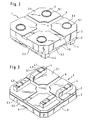
- the in the FIGS. 1 . 2 and 3 illustrated packaging 1 consists of the lower part 2 and the upper part 3, which define between them a non-visible space for receiving a large roller bearing.
- Both the lower part 2 and the upper part 3 consist of a base plate 2.1, 3.1 of the perpendicularly arranged side walls 2.2, 3.2 extend upwards and downwards, which are coordinated so that the lower part 2 and upper part 3 are slipped into each other, similar to Principle of a cake box.
- the lower part 2 is provided with stacking elements 4, which are formed approximately rectangular and each have two arcuate recesses 4.1, so that a substantially niksegmentartiger projection 4.2 is formed.
- both the upper side of the upper part 3 and the lower side of the lower part 2 are provided with reliefs 6 which in the present case intersect at the center. These serve to receive a tensioning means, for example a belt, and ensure that the upper part 3 can not be detached from the lower part 2 of the packaging 1.
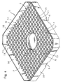
- FIGS. 4 and 5 are inner sides of upper parts 3 of a package 1 shown, which are equipped with openings 7, 8. These are formed in the first case by mutually parallel webs 7.1, 7.2, which are employed in longitudinal and transverse rows to each other. The webs 7.1, 7.2 are connected to the base plate 3.1 of the upper part 3, so that the waffle-like openings 7 are formed.
- the openings 8 are formed by circularly arranged, in the radial direction of spaced webs 8.1, which are connected at several circumferential locations with parallel to the side walls 3.2 extending webs 8.2.
- the type and position of the webs 7.1, 7.2, 8.1, 8.2 is ultimately irrelevant, it is only important that a high stability of the part is achieved.
- the FIGS. 4 and 5 show further that in both cases in the upper part 3, a circularly formed exemption 9 is present.
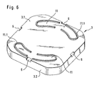
- FIGS. 7 and 6 are shown differently configured stacking elements consisting of the arcuate segments 10 which engage in associated recesses 11.
- the recess 11 is bounded by beads 11.1, which enclose the arcuate segments 10 and thus prevent slipping.
- FIGS. 8 to 13 The actual invention, according to which it is important to make the same packaging suitable for size differently sized slewing bearings, goes out of the FIGS. 8 to 13 forth, first that in the FIGS. 10, 10a . 11, 12 and 13 shown retaining element is described in detail.
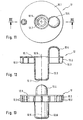
- the retaining element denoted by 12 can be produced in one piece as an injection-molded part in a simple manner and consists of the circular base plate 12.1, whose lateral surface 12.2 is provided with a toothing 12.3.
- the pin 12.4 is arranged, which is offset eccentrically to the axis of rotation 12.5 of the retaining element 12 is positioned.
- the underside of the base plate 12.1 is provided with the centrally arranged cylindrical pin 12.6, which extends in the opposite axial direction as the pin 12.4.
- this pin may be 12.6 provided on its lower end face with the positive locking element 12.7 or slightly conical. In this way it is prevented that the retaining element 12 can fall out of the lower part 2 when not engaged large rolling bearing 15.
- the eccentrically staggered pin 12.4 moves on a circular path, so that different distances of the pin 12.4 are adjustable from a center of the package 1, as the FIGS. 8 and 9 demonstrate.
- the top of the base plate 12.1 of the support member 12 is provided with a circumferential scale 12.8.
- the given numerical values in the range of 270 - 370 correspond to the diameter of the slewing bearings in mm. If a corresponding value is brought into conformity with the marking 13.3 of the side wall 13.1, then the eccentrically offset pin 12.4 of the holding element 12 is exactly in the correct position to bear against the outer surface of the relevant large-diameter rolling bearing.
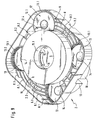
- the base plate 2.1 is provided with a radial direction of spaced, circular webs 8.1, which at four equally spaced circumferential locations are connected parallel to the side walls 2.2 extending webs 8.2, wherein the circular recess 9 is formed centrally.
- the circularly extending webs 8.1 are interrupted in each corner region by a first circular clearance 13, which is bounded by the 360 ° circumferential side wall 13.1. While the side wall 13.1 is provided with the toothing 13.2, the first free space 13 is continued by a second free space 14, which is smaller in diameter than the free space 13.
- FIG. 9 shows, designated 15 and schematically illustrated large roller bearing is placed on the inside of the lower part 2 so that its designated 15.1 inner bore coincides approximately with the exemption 9.
- the holding elements designated 12 were introduced so that their eccentric to the axis of rotation 12.5 staggered pins 12.4 on the lateral surface of the large roller bearing 15 come to rest.
- the large roller bearing 15 is encompassed at four circumferential locations by the pins 12.4, so that it can not slip, the large roller bearing 15 rests on a portion of the base plate 12.1 of the support member 12. While the holding element 12 is guided with its pin 12.6 in the second free space 14, its base plate 12.1 is housed in the first free space 13.
- the radially outwardly directed toothing 12.3 of the retaining element 12 engages in the radially inwardly directed toothing 13.2 of the side wall 13.1, so that the retaining element 12 is fixed in a form-fitting manner in the first free space 13.
- the first is first lifted by being retracted with a hoist in the columns 16, which are limited by the rectilinear webs 8.2.
- the holding elements 12 are first removed from the two free spaces 13, 14, to then be used again so that their pins 12.4 arrive at the enlarged in diameter lateral surface of the large rolling bearing 15 to the plant.
- FIG. 9 can further recognize that in the package 1 and large rolling bearings 15 are accommodated with a different axial width, because the side walls 2.2 of the lower part 2 with the side walls 3.2 of the upper part 3 (not shown) cover in their height expansion. Without inserted large roller bearing 15, the overlap of the side walls 2.2, 3.2 largest and it decreases with increasing axial width of the large roller bearing 15. In other words, the distance between the base plate 2.1 of the lower part 2 of the base plate 3.1 of the upper part 3 is determined by the axial width of the large roller bearing 15.
- the packaging of only one slewing bearing is described in the embodiments described above, the invention should also extend to multi-piece packaging. This means that a plurality of large roller bearings can be accommodated in a packaging unit, which are then accommodated in the manner described.
Landscapes
- Engineering & Computer Science (AREA)
- Mechanical Engineering (AREA)
- General Engineering & Computer Science (AREA)
- Packaging Of Machine Parts And Wound Products (AREA)
- Stackable Containers (AREA)
- Packaging Of Annular Or Rod-Shaped Articles, Wearing Apparel, Cassettes, Or The Like (AREA)
- Pallets (AREA)
- Containers Having Bodies Formed In One Piece (AREA)
- Details Of Rigid Or Semi-Rigid Containers (AREA)
- Packages (AREA)
- Apparatus For Radiation Diagnosis (AREA)
Description
- Die Erfindung betrifft eine Verpackung für den Versand und die Handhabung von Großwälzlagern, bestehend aus einem Unterteil und einem Oberteil, die ineinander stülpbar sind und zwischen sich einen Raum zur Aufnahme wenigstens eines Großwälzlagers begrenzen. Im Sinne der Erfindung ist dabei der Begriff Großwälzlager so auszulegen, dass darunter auch dessen Lagerbestandteile, wie beispielsweise ein Lagerinnen- oder ein Lageraußenring, fallen. Aber auch für völlig andersartige rotationssymmetrische Teile erscheint die Erfindung anwendbar.
- Der Fachmann versteht unter Großwälzlagern Lagereinheiten, deren Durchmesser sich etwa im Bereich zwischen 360 und 610 mm bewegen. Bedingt durch diese großen Abmessungen ergeben sich Lagergewichte von 30 kg und mehr. Es liegt auf der Hand, dass derartige Großwälzlager für den Transport entsprechend verpackt werden müssen, um sie sicher handhaben zu können.
- In diesem Zusammenhang ist es allgemein bekannt, dass solche Lager in Kisten aus Holz verpackt werden, wobei das Wälzlager vor dem Einsetzen in die Kiste entweder mit Kunststoffband umwickelt oder mit Hilfe von Beuteln und Wellpappe geschützt wird. Diese Verpackungsart erfordert jedoch eine aufwendige Packmittelvorbereitung und ist daher teuer. Beispielsweise ist der Wickelprozess sehr zeitaufwendig. Darüber hinaus sind die Holzkisten den jeweiligen Außenmaßen des Großwälzlagers anzupassen und es ist entsprechend viel Polstermaterial zu verwenden, das wiederum entsorgt werden muß.
- Aus den deutschen Geschmacksmusteranmeldungen
Nr. 401 07 626 ,401 07 641 ,401 07 642 ,402 03 397 sind Lagerbehältnisse für Lager und dessen Teile bekannt geworden, die aus einem Unterteil und einem Oberteil bestehen. Beide Teile sind ineinander stülpbar und begrenzen zwischen sich einen Raum zur Aufnahme des Großwälzlagers. - Nachteilig dabei ist, dass derartige Lagerbehältnisse immer auf die verwendete Lagergröße abzustimmen sind. Dies erfolgt derart, dass im Lagerbehältnis Einsätze vorhanden sind, die das Lager aufnehmen. Diese Einsätze sind den jeweiligen Lagergrößen anzupassen. Der Lagerhersteller muß demnach eine Vielzahl von unterschiedlich dimensionierten Einsätzen bereitstellen, was die gesamte Verpackung wiederum kostenmäßig in unnötiger Weise belastet.
- Ausgehend von den bekannten Nachteilen des Standes der Technik liegt der Erfindung daher die Aufgabe zugrunde, eine Verpackung für Großwälzlager bereitzustellen, die universell anwendbar ist.
- Erfindungsgemäß wird diese Aufgabe nach dem kennzeichnenden Teil von Anspruch 1 in Verbindung mit dessen Oberbegriff dadurch gelöst, dass eine äußere Mantelfläche des Großwälzlagers an mehreren voneinander beabstandeten Umfangsstellen von einem feststellbaren Halteelement umgriffen ist, wobei das mit dem Unterteil lösbar verbundene Halteelement in seiner Stellung derart veränderbar ist, dass sein Abstand bezogen auf einen Mittelpunkt der Verpackung vergrößer- oder verkleinerbar ist.
- Der Vorteil der erfindungsgemäßen Lösung liegt darin, dass von der gleichen Verpackung unterschiedlich groß dimensionierte Lager aufgenommen werden können. Dies wird dadurch ermöglicht, dass das Halteelement, das das Großwälzlager oder einen Lagerbestandteil, beispielsweise den Wälzlageraußenring, an mehreren voneinander beabstandeten Umfangsstellen umgreift, in seiner Position veränderbar ist. Das bedeutet, das Halteelement wird in Abhängigkeit von jeweiligen Umfang des Großwälzlagers an einer bestimmten Stelle mit dem Unterteil verbunden, so dass es an dessen Mantelfläche anliegt. Wird nun von der gleichen Verpackung ein größeres oder ein kleineres Großwälzlager aufgenommen, so wird das Halteelement entsprechend versetzt, so dass sein Abstand bezogen auf den Mittelpunkt der Verpackung vergrößert oder verkleinert ist und es stets an der Mantelfläche des jeweiligen Großwälzlagers anliegt. Auf dies Weise ist das Großwälzlager an verschiedenen Umfangsstellen umgriffen und in der Verpackung sicher fixiert. Das Fixieren des Großwälzlagers in der Verpackung ist von besonderer Bedeutung, da dieses wahlweise mit Straßenfahrzeugen. Schienenfahrzeugen, mit Schiffen oder in Flugzeugen transportiert wird und somit vielfältigen Bewegungen ausgesetzt ist.
- Weitere vorteilhafte Ausgestaltungen der Erfindung sind in den Unteransprüchen beschrieben.
- So ist nach Anspruch 2 vorgesehen, dass das Halteelement mit dem Unterteil durch Form- und/oder Kraftschluß verbunden ist. Vorteilhafter Weise wird man eine formschlüssige Verbindung allerdings bevorzugen, da auf diese Art und Weise eine besonders einfache Trennung von Halteelement und Unterteil möglich ist.
- Eine besonders vorteilhafte Ausführungsvariante des Halteelements geht aus Anspruch 3 hervor. Danach ist vorgesehen, dass auf einer Oberseite einer kreisförmig ausgebildeten Grundplatte ein exzentrisch versetzt angeordneter Stift angeordnet ist, während eine Unterseite der Grundplatte mit einem zentrisch angeordneten zylindrisch Zapfen versehen ist. Die Grundplatte ist nun in verschiedenen Umfangsstellungen in das Unterteil einsteckbar, so dass der exzentrisch versetzt angeordnete Stift sich auf einer kreisförmigen Umlaufbahn bewegen kann und an jeder Stelle seiner Umlaufbahn arretierbar ist, so dass in Bezug auf einen Mittelpunkt der Verpackung immer ein unterschiedlicher Abstand einstellbar ist.
- Als vorteilhaft hat es sich in diesem Zusammenhang erwiesen, wenn gemäß Anspruch 4 die kreisförmig ausgebildete Grundplatte an ihrer Mantelfläche mit einer Verzahnung versehen ist, die in einen zugehörigen, ebenfalls mit einer Verzahnung versehenen kreisförmigen Freiraum des Unterteils eingreift. Auf diese Weise ist durch eine entsprechende formschlüssige Verbindung sichergestellt, dass die Grundplatte an der Stelle arretiert ist, an der der exzentrisch versetzt angeordnete Stift die äußere Mantelfläche des Großwälzlagers umgreift.
- Nach einem weiteren Merkmal der Erfindung gemäß Anspruch 5 ist vorgesehen, dass die Oberseite der kreisförmig ausgebildeten Grundplatte mit einer Skalierung versehen ist, die mit einer Markierung in der Seitenwand des ersten Freiraums in Übereinstimmung bringbar ist. Die Übereinstimmung von Skalierung und Markierung sorgt dafür, dass das Halteelement mit seinem exzentrisch versetzt angeordneten Stift genau an der Stelle positioniert werden kann, an der sich die Mantelfläche des jeweiligen Großwälzlagers erstreckt.
- Als vorteilhaft hat es sich nach Anspruch 6 erwiesen, wenn der zylindrische Zapfen an seiner Stirnseite mit einem Formschlusselement versehen ist, das in ein zugehöriges Formschlusselement im Unterteil eingreift. Dadurch wird verhindert, dass das Halteelement im unbelasteten Zustand, d. h., ohne ein Großwälzlager, in der Verpackung lose herumliegt.
- Nach einem weiteren zusätzlichen Merkmal gemäß Anspruch 7 ist vorgesehen, dass die Innenseite des Unter- und/oder des Oberteils mit senkrecht angeordneten Durchbrechungen versehen ist. Diese Durchbrechungen sorgen für eine erhöhte Stabilität von Ober- und Unterteil, die bei dem vorhanden Gewicht der Großwälzlager auch unbedingt gegeben sein muß. Die Art der senkrecht angeordneten Durchbrechungen ist dabei beliebig, d. h., im Vordergrund steht lediglich die Stabilität.
- Nach Anspruch 8 ist vorgesehen, dass die Durchbrechungen durch parallel zueinander angeordnete Stege gebildet sind, welche in Längs- und in Querreihen zueinander angestellt sind. Eine andere Ausbildung der Durchbrechungen geht aus Anspruch 9 hervor. Danach sollen diese durch kreisförmig angeordnete, in radialer Richtung voneinander beabstandete Stege gebildet sein, wobei wenigstens an einer Umfangsstelle parallel zu einer Seitenkante verlaufende Stege angeordnet sind.
- Nach einem zusätzlichen weiteren Merkmal der Erfindung gemäß Anspruch 10 soll das Ober- und/oder das Unterteil an seiner Innenseite mit einer zentrisch angeordneten Freistellung versehen sein. Diese Freistellung ist besonders für das Unterteil von maßgebender Bedeutung, da sie zur Entnahme des Großwälzlagers dient. Die erfolgt derart, dass mit einem Hebemittel das Großwälzlager ausgehend von der Freistellung untergriffen wird und somit heraushebbar ist.
- Nach einem weiteren Merkmal der Erfindung gemäß Anspruch 11 ist vorgesehen, dass das Unterteil an seiner Außenseite mit hervorstehenden Stapelelementen versehen ist, die in zugehörige, auf der Oberseite des Oberteils angeordnete Ausnehmungen eingreifen. Wie der Name schon sagt, sorgen die Stapelelemente dafür, dass ein sicheres Stapeln von Verpackungen möglich ist. Entweder wird eine Verpackung genau über die andere Verpackung gestapelt oder es wird eine Verpackung auf Lücke über zwei Verpackungen gestapelt. Die Ausbildung der Stapelelemente ist dabei zweitrangig, d.h., diese können unterschiedliche Gestalt aufweisen.
- Nach Anspruch 12 ist vorgesehen, dass diese zylinderförmig ausgebildet sind und in kreisrunde Ausnehmungen eingreifen. Aus Anspruch 13 geht hervor, dass diese rechteckig ausgebildet sind und einen kreissegmentartigen Vorsprung besitzen.
- Nach einem weiteren zusätzlichen Merkmal der Erfindung gemäß Anspruch 14 sollen die Oberseite des Oberteils und die Unterseite des Unterteils mit Freistellungen zur Aufnahme eines Spannmittel versehen sein. Dieses Spannmittel sorgt dafür, dass sich das Oberteil nicht vom Unterteil der Verpackung lösen kann.
- Aus Anspruch 15 geht hervor, dass die Verpackung aus einem gegen Schmierstoff und Korrosionsschutzmittel unempfindlichen Kunststoff hergestellt sein soll. Dies ist erforderlich, da das Verpackungsmaterial auch bei sehr langen Transportzeiten oder bei sehr langen Lagerzeiten keinen Schaden durch die genannten Stoffe nehmen darf, um wieder verwendungsfähig zu sein.
- Auch ist nach dem Anspruch 16 vorgesehen, dass wenigstens das Oberteil der Verpackung aus einem durchsichtigen Kunststoff hergestellt ist. Dies ist von Vorteil, da eine visuelle Kontrolle des Inhaltes der Verpackung ohne Demontage jederzeit unkompliziert möglich ist.
- Wie Anspruch 17 erkennen lässt, sollen sich die Seitenwände vom Unterteil und vom Oberteil in ihrer Höhenausdehnung überdecken. Der Vorteil dieser Ausführungsvariante liegt darin, dass in der Verpackung nicht nur Großwälzlager unterschiedlichen Durchmessers, sondern auch unterschiedlicher axialer Breite unterbringbar sind. Je breiter die Wälzlager in axialer Richtung sind, um so geringer wird die Überdeckung der Seitenwände von Unterteil und Oberteil ausfallen, da das Oberteil vom Lager praktisch angehoben wird. Oder anders ausgedrückt, der Abstand der Grundplatte des Unterteils von der Grundplatte des Oberteils wird von der axialen Breite des Ladegutes bestimmt.
- Die Erfindung wird an nachstehenden Ausführungsbeispielen näher erläutert.
- Es zeigen:
- Figur 1
- zwei übereinander gestapelte Verpackungen,
- Figuren 2,3
- je eine Draufsicht von oben und von unten auf eine Verpackung,
- Figuren 4,5
- je eine Draufsicht auf ein Oberteil von innen,
- Figur 6
- eine Draufsicht auf ein Oberteil von oben,
- Figur 7
- eine Draufsicht auf ein Unterteil von unten,
- Figuren 8,9
- je eine Draufsicht auf ein Unterteil mit eingelegtem Halteelement und mit eingelegtem Halteelement und Lager,
- Figur 10
- eine perspektivische Darstellung eines Halteelementes,
- Figur 10a
- eine Draufsicht auf ein im Unterteil angeordnetes Halteelement,
- Figur 11
- eine Draufsicht auf ein Halteelement,
- Figur 12
- einen Schnitt entlang der Linie XII - XII in
Figur 11 und - Figur 13
- eine Seitenansicht eines Halteelements.
- Die in den
Figuren 1 ,2 und 3 dargestellte Verpackung 1 besteht aus dem Unterteil 2 und dem Oberteil 3, die zwischen sich einen nicht sichtbaren Raum zur Aufnahme eines Großwälzlagers begrenzen. Sowohl das Unterteil 2 als auch das Oberteil 3 bestehen aus einer Grundplatte 2.1, 3.1 von der sich rechtwinklig angeordnete Seitenwände 2.2, 3.2 nach oben und nach unten erstrecken, die so aufeinander abgestimmt sind, dass Unterteil 2 und Oberteil 3 ineinander stülpbar sind, ähnlich dem Prinzip einer Tortenschachtel. Das Unterteil 2 ist mit Stapelelementen 4 versehen, die in etwa rechteckig ausgebildet sind und je zwei bogenförmige Ausnehmungen 4.1 aufweisen, so daß ein im Wesentlichen kreissegmentartiger Vorsprung 4.2 gebildet ist. Auf dem Oberteil 3 sind zugehörige Ausnehmungen 5 gebildet, welche von vier bogenförmigen Wülsten 5.1 begrenzt sind. Stapelelement 4 und zugehörige Ausnehmung 5 müssen nun so aufeinander abgestimmt sein, dass ein Verrutschen der gemäßFigur 1 übereinander angeordneten Verpackungen 1 verhindert ist. Dies erfolgt derart, dass die Wulst 5.1 des Oberteils 3 in die bogenförmige Ausnehmung 4.1 des Stapelelements 4 des Unterteils 2 eingreift. Wie aus den genannten Figuren weiter ersichtlich, sind sowohl die Oberseite des Oberteils 3 als auch die Unterseite des Unterteils 2 mit Freistellungen 6 versehen, die sich im vorliegenden Fall im Mittelpunkt kreuzen. Diese dienen zur Aufnahme eines Spannmittels, beispielsweise eines Riemens, und sorgen dafür, dass sich das Oberteil 3 nicht vom Unterteil 2 der Verpackung 1 lösen kann. - In den
Figuren 4 und5 sind Innenseiten von Oberteilen 3 einer Verpackung 1 gezeigt, welche mit Durchbrechungen 7, 8 ausgestattet sind. Diese werden im ersten Fall durch parallel zueinander angeordnete Stege 7.1, 7.2 gebildet, die in Längs- und in Querreihen zueinander angestellt sind. Die Stege 7.1, 7.2 sind dabei mit der Grundplatte 3.1 des Oberteils 3 verbunden, so dass die waffelartig angeordneten Durchbrechungen 7 gebildet sind. Im zweiten Fall sind die Durchbrechungen 8 durch kreisförmig angeordnete, in radialer Richtung von einander beabstandete Stege 8.1 gebildet, welche an mehreren Umfangsstellen mit parallel zu den Seitenwänden 3.2 verlaufenden Stegen 8.2 verbunden sind. Die Art und Lage der Stege 7.1, 7.2, 8.1, 8.2 ist letztendlich unerheblich, es kommt lediglich darauf an, dass eine hohe Stabilität des Teils erreicht wird. DieFiguren 4 und5 zeigen weiter, dass in beiden Fällen im Oberteil 3 eine kreisförmig ausgebildete Freistellung 9 vorhanden ist. - In den
Figuren 7 und6 sind andersartig ausgebildete Stapelelemente gezeigt, die aus den bogenförmigen Segmenten 10 bestehen, welche in zugehörige Ausnehmungen 11 eingreifen. Die Ausnehmung 11 wird dabei von Wülsten 11.1 begrenzt, die die bogenförmigen Segmente 10 umschließen und somit am Verrutschen hindern. - Die eigentliche Erfindung, nach der es darauf ankommt, die gleiche Verpackung für in der Größe unterschiedlich dimensionierte Großwälzlager verwendungsfähig zu machen, geht aus den
Figuren 8 bis 13 hervor, wobei zunächst das in denFiguren 10, 10a ,11, 12 und 13 dargestellte Halteelement näher beschrieben wird. - Das mit 12 bezeichnete Halteelement ist als Spritzgussteil in einfacher Weise einteilig herstellbar und besteht aus der kreisförmig ausgebildeten Grundplatte 12.1, deren Mantelfläche 12.2 mit einer Verzahnung 12.3 versehen ist. Auf der Oberseite der Grundplatte 12.1 ist der Stift 12.4 angeordnet, der exzentrisch versetzt zur Drehachse 12.5 des Halteelements 12 positioniert ist. Die Unterseite der Grundplatte 12.1 ist mit dem zentrisch angeordneten zylindrischen Zapfen 12.6 versehen, der sich in entgegengesetzter axialer Richtung als der Stift 12.4 erstreckt. Wie die
Figuren 12 und 13 zeigen, kann dieser Zapfen 12.6 an seiner unteren Stirnseite mit dem Formschlusselement 12.7 versehen oder leicht konisch ausgebildet sein. Auf diese Weise ist verhindert, dass das Halteelement 12 aus dem Unterteil 2 bei nicht eingelegtem Großwälzlager 15 herausfallen kann. Bei Drehung des Halteelementes 12 um seine Achse 12.5 bewegt sich der exzentrisch versetzt angeordnete Stift 12.4 auf einer Kreisbahn, so dass unterschiedliche Abstände des Stiftes 12.4 von einem Zentrum der Verpackung 1 einstellbar sind, wie dieFiguren 8 und9 zeigen. - Wie aus
Figur 10a erkennbar, ist es vorteilhaft, wenn die Oberseite der Grundplatte 12.1 des Halteelements 12 mit einer umlaufenden Skalierung 12.8 versehen ist. Die angegebenen Zahlenwerte im Bereich von 270 - 370 entsprechen dem Durchmesser der Großwälzlager in mm. Wird ein entsprechender Wert mit der Markierung 13.3 der Seitenwand 13.1 in Übereinstimmung gebracht, so steht der exzentrisch versetzte Stift 12.4 des Halteelements 12 genau in richtiger Position zur Anlage an der äußeren Mantelfläche des betreffenden Großwälzlagers. - Das in den
Figuren 8 und9 gezeigte Unterteil 2 der Verpackung 1 ist in der bereits unterFigur 5 beschriebenen Weise mit Durchbrechungen 8 zur Erhöhung seiner mechanischen Stabilität versehen. Dazu ist die Grundplatte 2.1 mit ein radialer Richtung von einander beabstandeten, kreisförmigen Stegen 8.1 versehen, die an vier gleichmäßig voneinander beabstandeten Umfangsstellen mit parallel zu den Seitenwänden 2.2 verlaufenden Stegen 8.2 verbunden sind, wobei mittig die kreisförmige Freistellung 9 gebildet ist. Die kreisförmig verlaufenden Stege 8.1 sind in jeden Eckbereich von einem ersten kreisrunden Freiraum 13 unterbrochen, der durch die um 360° umlaufende Seitenwand 13.1 begrenzt ist. Während die Seitenwand 13.1 mit der Verzahnung 13.2 versehen ist, ist der erste Freiraum 13 durch einen zweiten Freiraum 14 fortgesetzt, der im Durchmesser kleiner als der Freiraum 13 ist. - Wie insbesondere
Figur 9 zeigt, wird das mit 15 bezeichnete und schematisch dargestellte Großwälzlager auf die Innenseite des Unterteils 2 so abgelegt, dass seine mit 15.1 bezeichnete Innenbohrung in etwa mit der Freistellung 9 übereinstimmt. Davor wurden die mit 12 bezeichneten Halteelemente so eingeführt, dass deren exzentrisch zur Drehachse 12.5 versetzt angeordneten Stifte 12.4 an der Mantelfläche des Großwälzlagers 15 zur Anlage gelangen. Auf diese Weise ist das Großwälzlager 15 an vier Umfangsstellen durch die Stifte 12.4 umgriffen, so dass es nicht verrutschen kann, wobei das Großwälzlager 15 auf einem Teil der Grundplatte 12.1 des Halteelements 12 aufliegt. Während das Halteelement 12 mit seinem Zapfen 12.6 im zweiten Freiraum 14 geführt ist, ist dessen Grundplatte 12.1 im ersten Freiraum 13 untergebracht. Dabei greift die radial nach außen gerichtete Verzahnung 12.3 des Halteelementes 12 in die radial nach innen gerichtete Verzahnung 13.2 der Seitenwand 13.1 ein, so dass das Halteelement 12 im ersten Freiraum 13 formschlüssig festgelegt ist. Wird nun das Großwälzlager 15 durch ein im Durchmesser gröβeres ersetzt, so wird zunächst das erste herausgehoben, indem mit einem Hebezeug in die Spalten 16 eingefahren wird, welche durch die geradlinig ausgebildeten Stege 8.2 begrenzt sind. Danach werden die Halteelemente 12 zunächst aus den beiden Freiräumen 13, 14 entfernt, um anschließend wieder so eingesetzt zu werden, dass deren Stifte 12.4 an der im Durchmesser vergrößerten Mantelfläche des Großwälzlagers 15 zur Anlage gelangen. -
Figur 9 läßt weiter erkennen, dass in der Verpackung 1 auch Großwälzlager 15 mit einer unterschiedlichen axialen Breite unterbringbar sind, weil sich die Seitenwände 2.2 von Unterteil 2 mit den Seitenwänden 3.2 des Oberteils 3 (nicht dargestellt) in ihrer Höhenausdehnung überdecken. Ohne eingesetztes Großwälzlager 15 ist die Überdeckung der Seitenwände 2.2, 3.2 am größten und sie nimmt mit zunehmender axialer Breite des Großwälzlagers 15 ab. Anders ausgedrückt, der Abstand der Grundplatte 2.1 des Unterteils 2 von der Grundplatte 3.1 des Oberteils 3 wird von der axialen Breite des Großwälzlagers 15 bestimmt. - An dieser Stelle sei abschließend darauf hingewiesen, dass an den vorstehend beschriebenen Ausführungsbeispielen zwar die Verpackung nur eines Großwälzlagers beschrieben ist, die Erfindung sich aber auch auf Mehrstückverpackungen erstrecken soll. Dies bedeutet, dass in einer Verpackungseinheit mehrere Großwälzlager untergebracht sein können, die dann in der beschriebenen Weise aufgenommen sind.
-
- 1
- Verpackung
- 2
- Unterteil
- 2.1
- Grundplatte
- 2.2
- Seitenwand
- 3
- Oberteil
- 3.1
- Grundpaltte
- 3.2
- Seitenwand
- 4
- Stapelelement
- 4.1
- bogenförmige
Ausnehmung - 4.2
- Vorsprung
- 5
- Ausnehmung
- 5.1
- Wulst
- 6
- Freistellung
- 7
- Durchbrechung
- 7.1
- Steg
- 7.2
- Steg
- 8
- Durchbrechung
- 8.1
- Steg
- 8.2
- Steg
- 9
- Freistellung
- 10
- Stapelelement
- 11
- Ausnehmung
- 11.1
- Wulst
- 12
- Halteelement
- 12.1
- Grundplatte
- 12.2
- Mantelfläche
- 12.3
- Verzahnung
- 12.4
- Stift
- 12.5
- Drehachse
- 12.6
- Zapfen
- 12.7
- Formschlußelement
- 12.8
- Skalierung
- 13
- erster Freiraum
- 13.1
- Seitenwand
- 13.2
- Verzahnung
- 13.3
- Markierung
- 14
- zweiter Freiraum
- 15
- Großwälzlager
- 15.1
- Innenbohrung
- 16
- Spalt
Claims (17)
- Verpackung (1) für den Versand und die Handhabung von Großwälzlagern (15), bestehend aus einem Unterteil (2) und einem Oberteil (3), die ineinander stülpbar sind und zwischen sich einen Raum zur Aufnahme wenigstens eines Großwälzlagers (15) begrenzen, dadurch gekennzeichnet, dass eine äußere Mantelfläche des Großwälzlagers (15) an mehreren voneinander beabstandeten Umfangsstellen von einem feststellbaren Halteelement umgriffen ist, wobei das mit dem Unterteil (2) lösbar verbundene Halteelement in seiner Stellung derart veränderbar ist, dass sein Abstand bezogen auf einen Mittelpunkt der Verpackung (1) vergrößer- oder verkleinerbar ist.
- Verpackung (1) nach Anspruch 1, dadurch gekennzeichnet, dass das Halteelement mit dem Unterteil (2) durch Form- und/oder Kraftschluß verbunden ist.
- Verpackung (1) nach Anspruch 1, dadurch gekennzeichnet, dass an dem Halteelement (12) auf einer Oberseite einer kreisförmig ausgebildeten Grundplatte (12.1) ein exzentrisch versetzt angeordneter Stift (12.4) angeordnet ist, während eine Unterseite der Grundplatte (12.1) mit einem zentrisch angeordneten zylindrischen Zapfen (12.6) versehen ist.
- Verpackung (1) nach Anspruch 3, dadurch gekennzeichnet, dass die kreisförmig ausgebildete Grundplatte (12.1) des Halteelements (12) an ihrer Mantelfläche (12.2) mit einer Verzahnung (12.3) versehen ist, die in einen zugehörigen, ebenfalls mit einer Verzahnung (13.2) versehenen kreisförmigen Freiraum (13) des Unterteils (2) eingreift.
- Verpackung (1 ) nach Anspruch 3, dadurch gekennzeichnet, dass die Oberseite der kreisförmig ausgebildeten Grundplatte (12,1) des Halteelements (12) mit einer Skalierung (12.8) versehen ist, die mit einer Markierung (13.3) in der Seitenwand (13.1) des ersten Freiraums (13) in Übereinstimmung brinbar ist.
- Verpackung (1) nach Anspruch 3, dadurch gekennzeichnet, dass der zylindrische Zapfen (12.6) des Halteelements (12) an seiner Stirnseite mit einem Form-schlußelement (12.7) versehen ist, das in ein zugehöriges Formschluß-element im Unterteil (2) eingreift.
- Verpackung (1) nach Anspruch 1, dadurch gekennzeichnet, dass die Innenseite des Unter- (2) und/oder des Oberteils (3) mit senkrecht angeordneten Durchbrechungen (7,8) versehen ist.
- Verpackung (1) nach Anspruch 7, dadurch gekennzeichnet, dass die Durchbrechungen (7) durch parallel zueinander angeordnete Stege (7.1,7.2) gebildet sind, welche in Längs- und Querreihen zueinander angeordnet sind.
- Verpackung (1) nach Anspruch 7, dadurch gekennzeichnet, dass die Durchbrechungen (8) durch kreisförmig angeordnete, in radialer Richtung voneinander beabstandete Stege (8.1) gebildet sind, wobei wenigstens an einer Umfangsstelle parallel zu einer Seitenkante verlaufende Stege (8.2) angeordnet sind.
- Verpackung (1) nach Anspruch 1, dadurch gekennzeichnet, dass das Ober- (3) und/oder Unterteil (2) an seiner Innenseite mit einer zentrisch angeordneten Freistellung (9) versehen ist.
- Verpackung (1) nach Anspruch 1, dadurch gekennzeichnet, dass das Unterteil (2) an seiner Außenseite mit hervorstehenden Stapelelementen (4,10) versehen ist, die in zugehörige, auf der Oberseite des Oberteils (3) angeordnete Ausnehmungen (5,11) eingreifen.
- Verpackung (1) nach Anspruch 10, dadurch gekennzeichnet, dass die Stapelelemente zylinderförmig ausgebildet sind und in kreisrunde Ausnehmungen eingreifen.
- Verpackung (1) nach Anspruch 10, dadurch gekennzeichnet, dass die Stapelelemente (4) rechteckförmig ausgebildet sind und einen kreissegmentartigen Vorsprung (4.2) aufweisen.
- Verpackung (1) nach Anspruch 1, dadurch gekennzeichnet, dass die Oberseite des Oberteils (3) und die Unterseite des Unterteils (2) mit Freistellungen (6) zur Aufnahme eines Spannmittels versehen sind.
- Verpackung (1) nach Anspruch 1, dadurch gekennzeichnet, dass sie aus einem gegen Schmierstoff und Korrosionsschutzmittel unempfindlichen Kunststoff hergestellt ist.
- Verpackung (1) nach Anspruch 15, dadurch gekennzeichnet, dass wenigstens das Oberteil (3) aus einem durchsichtigen Kunststoff hergestellt ist.
- Verpackung (1) nach Anspruch 1, dadurch gekennzeichnet, dass sich die Seitenwände (2.2, 3.2) vom Unterteil (2) und vom Oberteil (3) in ihrer Höhenausdehnung überdecken.
Applications Claiming Priority (2)
| Application Number | Priority Date | Filing Date | Title |
|---|---|---|---|
| DE102004048286A DE102004048286B4 (de) | 2004-10-05 | 2004-10-05 | Verpackung für Großwälzlager |
| PCT/EP2005/010096 WO2006037457A1 (de) | 2004-10-05 | 2005-09-20 | Verpackung für grosswälzlager |
Publications (2)
| Publication Number | Publication Date |
|---|---|
| EP1796986A1 EP1796986A1 (de) | 2007-06-20 |
| EP1796986B1 true EP1796986B1 (de) | 2008-11-26 |
Family
ID=35635379
Family Applications (1)
| Application Number | Title | Priority Date | Filing Date |
|---|---|---|---|
| EP05793521A Expired - Lifetime EP1796986B1 (de) | 2004-10-05 | 2005-09-20 | Verpackung für grosswälzlager |
Country Status (7)
| Country | Link |
|---|---|
| US (1) | US7562775B2 (de) |
| EP (1) | EP1796986B1 (de) |
| JP (1) | JP4709842B2 (de) |
| AT (1) | ATE415359T1 (de) |
| DE (2) | DE102004048286B4 (de) |
| RO (1) | RO122631B1 (de) |
| WO (1) | WO2006037457A1 (de) |
Families Citing this family (15)
| Publication number | Priority date | Publication date | Assignee | Title |
|---|---|---|---|---|
| USD593391S1 (en) * | 2007-03-26 | 2009-06-02 | Pneutools, Incorporated | Reversible fastener cap |
| BRPI0818691A2 (pt) * | 2007-10-02 | 2014-09-30 | Bayer Cropscience Ag | Métodos para melhorar o crescimento vegetal. |
| CN101559851B (zh) * | 2009-05-19 | 2011-02-16 | 好孩子儿童用品有限公司 | 轴承包装盒 |
| JP5598967B2 (ja) * | 2009-06-08 | 2014-10-01 | 三甲株式会社 | 軸受搬送用コンテナ |
| JP5658981B2 (ja) * | 2010-11-25 | 2015-01-28 | Ntn株式会社 | コンテナ |
| US9915282B2 (en) | 2012-06-06 | 2018-03-13 | Pneutools, Incorporated | Stacked caps with connecting stems |
| DE102012218637A1 (de) * | 2012-10-12 | 2014-04-17 | Aktiebolaget Skf | Transportverpackung für ein ringförmiges Lagerteil |
| EP2810887A1 (de) * | 2013-06-05 | 2014-12-10 | ALWA GmbH & Co. KG Konstruktion & Formenbau | Vorrichtung zur Aufnahme und Halterung von Gegenständen sowie Transportvorrichtung |
| US20160290404A1 (en) * | 2013-11-06 | 2016-10-06 | Aktiebolaget Skf | Packaging device for rolling element bearings |
| CN103922014B (zh) * | 2014-05-07 | 2016-02-24 | 广西玉柴机器股份有限公司 | 活塞环包装盒 |
| CN104608986B (zh) * | 2014-12-20 | 2018-04-24 | 新昌县小将永进轴承厂 | 一种防潮轴承储放箱 |
| US10370148B2 (en) * | 2016-01-19 | 2019-08-06 | Snacktops, Inc. | Mountable food container |
| KR200485819Y1 (ko) * | 2016-06-21 | 2018-02-27 | (주)선일플라스틱 | 베어링용 케이지 운반용 적치기구 |
| CN108100415A (zh) * | 2017-12-27 | 2018-06-01 | 新昌县隆豪轴承有限公司 | 一种存取方便的轴承存放箱 |
| US20250153899A1 (en) * | 2023-11-09 | 2025-05-15 | Doskocil Manufacturing Company, Inc. | Stackable container assembly |
Family Cites Families (23)
| Publication number | Priority date | Publication date | Assignee | Title |
|---|---|---|---|---|
| US2621807A (en) * | 1948-01-29 | 1952-12-16 | Edmund H Rendich | Display positioning device |
| US3089964A (en) * | 1954-09-30 | 1963-05-14 | Ibm | Inverter with output clamp and r-c circuit |
| US3080964A (en) * | 1959-05-01 | 1963-03-12 | Buckeye Molding Co | Container |
| FR1332570A (fr) * | 1962-04-06 | 1963-07-19 | Roulements A Aiguilles Sa | Perfectionnement au conditionnement des roulements à galets, aiguilles, billes ou autres |
| US3247955A (en) * | 1964-06-05 | 1966-04-26 | Timken Roller Bearing Co | Interlocking package for bearing assemblies |
| US3318443A (en) * | 1964-10-08 | 1967-05-09 | Donald A Hillis | Dispensing container for band saw blades |
| US4191291A (en) * | 1979-01-25 | 1980-03-04 | Brown Ronald W | Dental organizer and container |
| DE8018779U1 (de) * | 1980-07-12 | 1980-10-09 | Skf Kugellagerfabriken Gmbh | Halte- und Montagevorrichtung |
| DE3412661A1 (de) * | 1984-04-02 | 1985-10-10 | Fritzsche-Ludwig GmbH & Co KG, 1000 Berlin | Vorrichtung zum aufbewahren und zurschaustellen von gegenstaenden, insbesondere kugellagern, medaillen, muenzen und dgl. |
| JPS62203821A (ja) * | 1986-02-28 | 1987-09-08 | Iseki & Co Ltd | トラクタ−のエアクリ−ナ |
| US5037277A (en) * | 1989-07-26 | 1991-08-06 | Flow International Corporation | Poppet valve for a high pressure fluid pump |
| US5447234A (en) * | 1992-11-13 | 1995-09-05 | Eastman Kodak Company | Recyclable/reusable containers for packaging graphical sheet materials |
| US5685429A (en) * | 1992-11-13 | 1997-11-11 | Eastman Kodak Company | Adjustable chocking element |
| US5346065A (en) * | 1993-02-11 | 1994-09-13 | Minnesota Mining And Manufacturing Company | Media shipping container |
| DE9304895U1 (de) * | 1993-03-31 | 1993-06-17 | BASF Magnetics GmbH, 6800 Mannheim | Mehrweg-Sammelverpackung für gestapelte Wickelrollen |
| DE9409451U1 (de) * | 1994-06-01 | 1994-09-22 | Hp Haushaltprodukte Gmbh, 56410 Montabaur | Vorrichtung zum Aufnehmen und Bereithalten scheibenförmiger Gegenstände |
| US5755323A (en) * | 1996-04-09 | 1998-05-26 | The Timken Company | Package and kit for and method of selecting a replacement bearing |
| JPH1121021A (ja) * | 1997-07-08 | 1999-01-26 | N Ii C Logistics Kk | 円形物保管棚 |
| JPH11255271A (ja) * | 1998-03-11 | 1999-09-21 | Gifu Plast Ind Co Ltd | 小動物収容箱 |
| JP2000168778A (ja) * | 1998-12-10 | 2000-06-20 | Dainippon Ink & Chem Inc | 合成樹脂製容器 |
| JP4233197B2 (ja) * | 2000-06-27 | 2009-03-04 | 三甲株式会社 | 仕切容器 |
| JP2003128154A (ja) * | 2001-10-25 | 2003-05-08 | Mitsuaki Arita | 生花等の梱包用容器 |
| US20050274634A1 (en) * | 2004-03-05 | 2005-12-15 | Darryl Christmas | Container and system for constraining and paying out coiled steel rule or the like |
-
2004
- 2004-10-05 DE DE102004048286A patent/DE102004048286B4/de not_active Expired - Fee Related
-
2005
- 2005-09-20 RO ROA200700222A patent/RO122631B1/ro unknown
- 2005-09-20 WO PCT/EP2005/010096 patent/WO2006037457A1/de not_active Ceased
- 2005-09-20 AT AT05793521T patent/ATE415359T1/de not_active IP Right Cessation
- 2005-09-20 US US11/576,551 patent/US7562775B2/en not_active Expired - Lifetime
- 2005-09-20 JP JP2007535044A patent/JP4709842B2/ja not_active Expired - Lifetime
- 2005-09-20 DE DE502005006095T patent/DE502005006095D1/de not_active Expired - Lifetime
- 2005-09-20 EP EP05793521A patent/EP1796986B1/de not_active Expired - Lifetime
Also Published As
| Publication number | Publication date |
|---|---|
| JP4709842B2 (ja) | 2011-06-29 |
| JP2008515730A (ja) | 2008-05-15 |
| US7562775B2 (en) | 2009-07-21 |
| DE102004048286A1 (de) | 2006-04-06 |
| US20080047853A1 (en) | 2008-02-28 |
| WO2006037457A1 (de) | 2006-04-13 |
| EP1796986A1 (de) | 2007-06-20 |
| DE102004048286B4 (de) | 2010-04-15 |
| ATE415359T1 (de) | 2008-12-15 |
| DE502005006095D1 (de) | 2009-01-08 |
| RO122631B1 (ro) | 2009-10-30 |
Similar Documents
| Publication | Publication Date | Title |
|---|---|---|
| DE102004048286B4 (de) | Verpackung für Großwälzlager | |
| DE2516337C3 (de) | Stapel aus einer Mehrzahl von verpackten, rollenartigen Artikeln | |
| EP2955123B1 (de) | Vorrichtung zum transportieren von stückgut und system damit | |
| EP1996487B1 (de) | Mehrfach verwendbare transporteinheit für folienrollen und dergleichen | |
| EP0764125B1 (de) | Vorrichtung und verfahren zum transport von gefahrgutbehältern in containern | |
| EP0535481B1 (de) | Stirnwand aus spanlos verformbarem Material für eine Wickelfolie | |
| DE69406626T2 (de) | Positioniervorrichtung für eine Spule und Verpackungsverfahren unter Benutzung dieser Vorrichtung | |
| DE4241115A1 (de) | Stirnwand aus Spritzgußmaterial für eine Wickelfolie | |
| DE7810193U1 (de) | Wickelkern fuer streifenfoermige materalien | |
| DE102005003765B4 (de) | Ladungsträger zur Festlegung von wenigstens einem Grosswälzlager | |
| DE102012024788B4 (de) | Palettenvorrichtung zum Stapeln von Gerüstrahmen | |
| DE69001768T2 (de) | Endkappen fuer behaelter. | |
| EP2583908A1 (de) | Lager- und Transportpalette | |
| DE202017100104U1 (de) | Vorrichtung zur Transportsicherung | |
| DE9102843U1 (de) | Zusammenlegbarer quaderförmiger Behälter | |
| EP3556677A1 (de) | Stapelbehälter und transportsystem für derartige behälter | |
| DE3790890C2 (de) | ||
| DE4018476C2 (de) | Behältersystem mit profilierten Platten und Vorrichtung zum Befüllen und Entladen hierfür | |
| DE29723338U1 (de) | Leichtbaubehälter für hängend zu transportierendes Gut | |
| DE4133842A1 (de) | Formstueck und griffrille fuer polyfaesser | |
| DE102016104262B3 (de) | Mehrweg-Transportbox | |
| DE202022104145U1 (de) | Wickeleinheit für band- oder kabelförmige Materialien | |
| DE102016107711A1 (de) | Vorrichtung und Verfahren zur Transportsicherung | |
| DE9103623U1 (de) | Palette | |
| WO2024223753A1 (de) | Set zur werkzeugfreien herstellung einer transportkiste, transportkiste, verwendung eines sets, verfahren zur montage einer transportkiste und verwendung einer transportkiste |
Legal Events
| Date | Code | Title | Description |
|---|---|---|---|
| PUAI | Public reference made under article 153(3) epc to a published international application that has entered the european phase |
Free format text: ORIGINAL CODE: 0009012 |
|
| 17P | Request for examination filed |
Effective date: 20070402 |
|
| AK | Designated contracting states |
Kind code of ref document: A1 Designated state(s): AT BE BG CH CY CZ DE DK EE ES FI FR GB GR HU IE IS IT LI LT LU LV MC NL PL PT RO SE SI SK TR |
|
| DAX | Request for extension of the european patent (deleted) | ||
| GRAP | Despatch of communication of intention to grant a patent |
Free format text: ORIGINAL CODE: EPIDOSNIGR1 |
|
| GRAS | Grant fee paid |
Free format text: ORIGINAL CODE: EPIDOSNIGR3 |
|
| GRAA | (expected) grant |
Free format text: ORIGINAL CODE: 0009210 |
|
| AK | Designated contracting states |
Kind code of ref document: B1 Designated state(s): AT BE BG CH CY CZ DE DK EE ES FI FR GB GR HU IE IS IT LI LT LU LV MC NL PL PT RO SE SI SK TR |
|
| REG | Reference to a national code |
Ref country code: GB Ref legal event code: FG4D Free format text: NOT ENGLISH |
|
| REG | Reference to a national code |
Ref country code: CH Ref legal event code: EP |
|
| REG | Reference to a national code |
Ref country code: IE Ref legal event code: FG4D Free format text: LANGUAGE OF EP DOCUMENT: GERMAN |
|
| REF | Corresponds to: |
Ref document number: 502005006095 Country of ref document: DE Date of ref document: 20090108 Kind code of ref document: P |
|
| REG | Reference to a national code |
Ref country code: SE Ref legal event code: TRGR |
|
| REG | Reference to a national code |
Ref country code: CH Ref legal event code: PUEA Owner name: SCHAEFFLER KG Free format text: SCHAEFFLER KG#INDUSTRIESTRASSE 1-3#91074 HERZOGENAURACH (DE) $ FAG KUGELFISCHER AG & CO. OHG#FT/SWE-TR POSTFACH 1260#97419 SCHWEINFURT (DE) -TRANSFER TO- SCHAEFFLER KG#INDUSTRIESTRASSE 1-3#91074 HERZOGENAURACH (DE) |
|
| RAP2 | Party data changed (patent owner data changed or rights of a patent transferred) |
Owner name: SCHAEFFLER KG |
|
| PG25 | Lapsed in a contracting state [announced via postgrant information from national office to epo] |
Ref country code: LT Free format text: LAPSE BECAUSE OF FAILURE TO SUBMIT A TRANSLATION OF THE DESCRIPTION OR TO PAY THE FEE WITHIN THE PRESCRIBED TIME-LIMIT Effective date: 20081126 Ref country code: ES Free format text: LAPSE BECAUSE OF FAILURE TO SUBMIT A TRANSLATION OF THE DESCRIPTION OR TO PAY THE FEE WITHIN THE PRESCRIBED TIME-LIMIT Effective date: 20090308 |
|
| NLV1 | Nl: lapsed or annulled due to failure to fulfill the requirements of art. 29p and 29m of the patents act | ||
| PG25 | Lapsed in a contracting state [announced via postgrant information from national office to epo] |
Ref country code: NL Free format text: LAPSE BECAUSE OF FAILURE TO SUBMIT A TRANSLATION OF THE DESCRIPTION OR TO PAY THE FEE WITHIN THE PRESCRIBED TIME-LIMIT Effective date: 20081126 Ref country code: LV Free format text: LAPSE BECAUSE OF FAILURE TO SUBMIT A TRANSLATION OF THE DESCRIPTION OR TO PAY THE FEE WITHIN THE PRESCRIBED TIME-LIMIT Effective date: 20081126 Ref country code: SI Free format text: LAPSE BECAUSE OF FAILURE TO SUBMIT A TRANSLATION OF THE DESCRIPTION OR TO PAY THE FEE WITHIN THE PRESCRIBED TIME-LIMIT Effective date: 20081126 Ref country code: IS Free format text: LAPSE BECAUSE OF FAILURE TO SUBMIT A TRANSLATION OF THE DESCRIPTION OR TO PAY THE FEE WITHIN THE PRESCRIBED TIME-LIMIT Effective date: 20090326 Ref country code: PL Free format text: LAPSE BECAUSE OF FAILURE TO SUBMIT A TRANSLATION OF THE DESCRIPTION OR TO PAY THE FEE WITHIN THE PRESCRIBED TIME-LIMIT Effective date: 20081126 Ref country code: FI Free format text: LAPSE BECAUSE OF FAILURE TO SUBMIT A TRANSLATION OF THE DESCRIPTION OR TO PAY THE FEE WITHIN THE PRESCRIBED TIME-LIMIT Effective date: 20081126 |
|
| REG | Reference to a national code |
Ref country code: IE Ref legal event code: FD4D |
|
| PG25 | Lapsed in a contracting state [announced via postgrant information from national office to epo] |
Ref country code: IE Free format text: LAPSE BECAUSE OF FAILURE TO SUBMIT A TRANSLATION OF THE DESCRIPTION OR TO PAY THE FEE WITHIN THE PRESCRIBED TIME-LIMIT Effective date: 20081126 Ref country code: DK Free format text: LAPSE BECAUSE OF FAILURE TO SUBMIT A TRANSLATION OF THE DESCRIPTION OR TO PAY THE FEE WITHIN THE PRESCRIBED TIME-LIMIT Effective date: 20081126 Ref country code: BG Free format text: LAPSE BECAUSE OF FAILURE TO SUBMIT A TRANSLATION OF THE DESCRIPTION OR TO PAY THE FEE WITHIN THE PRESCRIBED TIME-LIMIT Effective date: 20090226 Ref country code: EE Free format text: LAPSE BECAUSE OF FAILURE TO SUBMIT A TRANSLATION OF THE DESCRIPTION OR TO PAY THE FEE WITHIN THE PRESCRIBED TIME-LIMIT Effective date: 20081126 Ref country code: RO Free format text: LAPSE BECAUSE OF FAILURE TO SUBMIT A TRANSLATION OF THE DESCRIPTION OR TO PAY THE FEE WITHIN THE PRESCRIBED TIME-LIMIT Effective date: 20081126 |
|
| PG25 | Lapsed in a contracting state [announced via postgrant information from national office to epo] |
Ref country code: PT Free format text: LAPSE BECAUSE OF FAILURE TO SUBMIT A TRANSLATION OF THE DESCRIPTION OR TO PAY THE FEE WITHIN THE PRESCRIBED TIME-LIMIT Effective date: 20090427 Ref country code: CZ Free format text: LAPSE BECAUSE OF FAILURE TO SUBMIT A TRANSLATION OF THE DESCRIPTION OR TO PAY THE FEE WITHIN THE PRESCRIBED TIME-LIMIT Effective date: 20081126 |
|
| PLBE | No opposition filed within time limit |
Free format text: ORIGINAL CODE: 0009261 |
|
| STAA | Information on the status of an ep patent application or granted ep patent |
Free format text: STATUS: NO OPPOSITION FILED WITHIN TIME LIMIT |
|
| 26N | No opposition filed |
Effective date: 20090827 |
|
| BERE | Be: lapsed |
Owner name: FAG KUGELFISCHER AG & CO. OHG Effective date: 20090930 Owner name: SCHAEFFLER K.G. Effective date: 20090930 |
|
| PG25 | Lapsed in a contracting state [announced via postgrant information from national office to epo] |
Ref country code: MC Free format text: LAPSE BECAUSE OF NON-PAYMENT OF DUE FEES Effective date: 20090930 |
|
| REG | Reference to a national code |
Ref country code: CH Ref legal event code: PL |
|
| PG25 | Lapsed in a contracting state [announced via postgrant information from national office to epo] |
Ref country code: BE Free format text: LAPSE BECAUSE OF NON-PAYMENT OF DUE FEES Effective date: 20090930 |
|
| PG25 | Lapsed in a contracting state [announced via postgrant information from national office to epo] |
Ref country code: CH Free format text: LAPSE BECAUSE OF NON-PAYMENT OF DUE FEES Effective date: 20090930 Ref country code: LI Free format text: LAPSE BECAUSE OF NON-PAYMENT OF DUE FEES Effective date: 20090930 Ref country code: GR Free format text: LAPSE BECAUSE OF FAILURE TO SUBMIT A TRANSLATION OF THE DESCRIPTION OR TO PAY THE FEE WITHIN THE PRESCRIBED TIME-LIMIT Effective date: 20090227 |
|
| PG25 | Lapsed in a contracting state [announced via postgrant information from national office to epo] |
Ref country code: AT Free format text: LAPSE BECAUSE OF NON-PAYMENT OF DUE FEES Effective date: 20090920 |
|
| PGFP | Annual fee paid to national office [announced via postgrant information from national office to epo] |
Ref country code: IT Payment date: 20100930 Year of fee payment: 6 |
|
| PG25 | Lapsed in a contracting state [announced via postgrant information from national office to epo] |
Ref country code: LU Free format text: LAPSE BECAUSE OF NON-PAYMENT OF DUE FEES Effective date: 20090920 |
|
| PG25 | Lapsed in a contracting state [announced via postgrant information from national office to epo] |
Ref country code: HU Free format text: LAPSE BECAUSE OF FAILURE TO SUBMIT A TRANSLATION OF THE DESCRIPTION OR TO PAY THE FEE WITHIN THE PRESCRIBED TIME-LIMIT Effective date: 20090527 |
|
| PG25 | Lapsed in a contracting state [announced via postgrant information from national office to epo] |
Ref country code: TR Free format text: LAPSE BECAUSE OF FAILURE TO SUBMIT A TRANSLATION OF THE DESCRIPTION OR TO PAY THE FEE WITHIN THE PRESCRIBED TIME-LIMIT Effective date: 20081126 |
|
| PG25 | Lapsed in a contracting state [announced via postgrant information from national office to epo] |
Ref country code: CY Free format text: LAPSE BECAUSE OF FAILURE TO SUBMIT A TRANSLATION OF THE DESCRIPTION OR TO PAY THE FEE WITHIN THE PRESCRIBED TIME-LIMIT Effective date: 20081126 |
|
| PGFP | Annual fee paid to national office [announced via postgrant information from national office to epo] |
Ref country code: GB Payment date: 20110930 Year of fee payment: 7 |
|
| PGFP | Annual fee paid to national office [announced via postgrant information from national office to epo] |
Ref country code: FR Payment date: 20111012 Year of fee payment: 7 Ref country code: SE Payment date: 20110929 Year of fee payment: 7 |
|
| REG | Reference to a national code |
Ref country code: DE Ref legal event code: R081 Ref document number: 502005006095 Country of ref document: DE Owner name: FAG KUGELFISCHER AG & CO. OHG, DE Free format text: FORMER OWNER: FAG KUGELFISCHER AG & CO. OHG, SCHAEFFLER TECHNOLOGIES GMBH &, , DE Effective date: 20120828 Ref country code: DE Ref legal event code: R081 Ref document number: 502005006095 Country of ref document: DE Owner name: SCHAEFFLER TECHNOLOGIES AG & CO. KG, DE Free format text: FORMER OWNER: FAG KUGELFISCHER AG & CO. OHG, SCHAEFFLER TECHNOLOGIES GMBH &, , DE Effective date: 20120828 Ref country code: DE Ref legal event code: R081 Ref document number: 502005006095 Country of ref document: DE Owner name: SCHAEFFLER TECHNOLOGIES GMBH & CO. KG, DE Free format text: FORMER OWNER: FAG KUGELFISCHER AG & CO. OHG, SCHAEFFLER TECHNOLOGIES GMBH &, , DE Effective date: 20120828 Ref country code: DE Ref legal event code: R081 Ref document number: 502005006095 Country of ref document: DE Owner name: SCHAEFFLER TECHNOLOGIES AG & CO. KG, DE Free format text: FORMER OWNERS: FAG KUGELFISCHER AG & CO. OHG, 97421 SCHWEINFURT, DE; SCHAEFFLER TECHNOLOGIES GMBH & CO. KG, 91074 HERZOGENAURACH, DE Effective date: 20120828 Ref country code: DE Ref legal event code: R081 Ref document number: 502005006095 Country of ref document: DE Owner name: FAG KUGELFISCHER AG & CO. OHG, DE Free format text: FORMER OWNERS: FAG KUGELFISCHER AG & CO. OHG, 97421 SCHWEINFURT, DE; SCHAEFFLER TECHNOLOGIES GMBH & CO. KG, 91074 HERZOGENAURACH, DE Effective date: 20120828 |
|
| PG25 | Lapsed in a contracting state [announced via postgrant information from national office to epo] |
Ref country code: SE Free format text: LAPSE BECAUSE OF NON-PAYMENT OF DUE FEES Effective date: 20120921 |
|
| REG | Reference to a national code |
Ref country code: SE Ref legal event code: EUG |
|
| GBPC | Gb: european patent ceased through non-payment of renewal fee |
Effective date: 20120920 |
|
| REG | Reference to a national code |
Ref country code: FR Ref legal event code: ST Effective date: 20130531 |
|
| PG25 | Lapsed in a contracting state [announced via postgrant information from national office to epo] |
Ref country code: GB Free format text: LAPSE BECAUSE OF NON-PAYMENT OF DUE FEES Effective date: 20120920 |
|
| PG25 | Lapsed in a contracting state [announced via postgrant information from national office to epo] |
Ref country code: FR Free format text: LAPSE BECAUSE OF NON-PAYMENT OF DUE FEES Effective date: 20121001 Ref country code: IT Free format text: LAPSE BECAUSE OF NON-PAYMENT OF DUE FEES Effective date: 20120920 |
|
| REG | Reference to a national code |
Ref country code: DE Ref legal event code: R081 Ref document number: 502005006095 Country of ref document: DE Owner name: SCHAEFFLER TECHNOLOGIES GMBH & CO. KG, DE Free format text: FORMER OWNER: FAG KUGELFISCHER AG & CO. OHG, SCHAEFFLER TECHNOLOGIES AG & CO, , DE Effective date: 20140211 Ref country code: DE Ref legal event code: R081 Ref document number: 502005006095 Country of ref document: DE Owner name: FAG KUGELFISCHER AG & CO. OHG, DE Free format text: FORMER OWNER: FAG KUGELFISCHER AG & CO. OHG, SCHAEFFLER TECHNOLOGIES AG & CO, , DE Effective date: 20140211 Ref country code: DE Ref legal event code: R081 Ref document number: 502005006095 Country of ref document: DE Owner name: SCHAEFFLER TECHNOLOGIES AG & CO. KG, DE Free format text: FORMER OWNER: FAG KUGELFISCHER AG & CO. OHG, SCHAEFFLER TECHNOLOGIES AG & CO, , DE Effective date: 20140211 Ref country code: DE Ref legal event code: R081 Ref document number: 502005006095 Country of ref document: DE Owner name: FAG KUGELFISCHER AG & CO. OHG, DE Free format text: FORMER OWNERS: FAG KUGELFISCHER AG & CO. OHG, 97421 SCHWEINFURT, DE; SCHAEFFLER TECHNOLOGIES AG & CO. KG, 91074 HERZOGENAURACH, DE Effective date: 20140211 Ref country code: DE Ref legal event code: R081 Ref document number: 502005006095 Country of ref document: DE Owner name: SCHAEFFLER TECHNOLOGIES AG & CO. KG, DE Free format text: FORMER OWNERS: FAG KUGELFISCHER AG & CO. OHG, 97421 SCHWEINFURT, DE; SCHAEFFLER TECHNOLOGIES AG & CO. KG, 91074 HERZOGENAURACH, DE Effective date: 20140211 |
|
| REG | Reference to a national code |
Ref country code: DE Ref legal event code: R081 Ref document number: 502005006095 Country of ref document: DE Owner name: SCHAEFFLER TECHNOLOGIES AG & CO. KG, DE Free format text: FORMER OWNERS: FAG KUGELFISCHER AG & CO. OHG, 97421 SCHWEINFURT, DE; SCHAEFFLER TECHNOLOGIES GMBH & CO. KG, 91074 HERZOGENAURACH, DE Effective date: 20150323 Ref country code: DE Ref legal event code: R081 Ref document number: 502005006095 Country of ref document: DE Owner name: FAG KUGELFISCHER AG & CO. OHG, DE Free format text: FORMER OWNERS: FAG KUGELFISCHER AG & CO. OHG, 97421 SCHWEINFURT, DE; SCHAEFFLER TECHNOLOGIES GMBH & CO. KG, 91074 HERZOGENAURACH, DE Effective date: 20150323 Ref country code: DE Ref legal event code: R081 Ref document number: 502005006095 Country of ref document: DE Owner name: FAG KUGELFISCHER AG & CO. OHG, DE Free format text: FORMER OWNER: FAG KUGELFISCHER AG & CO. OHG, SCHAEFFLER TECHNOLOGIES GMBH &, , DE Effective date: 20150323 Ref country code: DE Ref legal event code: R081 Ref document number: 502005006095 Country of ref document: DE Owner name: SCHAEFFLER TECHNOLOGIES AG & CO. KG, DE Free format text: FORMER OWNER: FAG KUGELFISCHER AG & CO. OHG, SCHAEFFLER TECHNOLOGIES GMBH &, , DE Effective date: 20150323 |
|
| P01 | Opt-out of the competence of the unified patent court (upc) registered |
Effective date: 20230523 |
|
| PGFP | Annual fee paid to national office [announced via postgrant information from national office to epo] |
Ref country code: SK Payment date: 20240920 Year of fee payment: 20 |
|
| PGFP | Annual fee paid to national office [announced via postgrant information from national office to epo] |
Ref country code: DE Payment date: 20241120 Year of fee payment: 20 |
|
| REG | Reference to a national code |
Ref country code: DE Ref legal event code: R071 Ref document number: 502005006095 Country of ref document: DE |
|
| REG | Reference to a national code |
Ref country code: SK Ref legal event code: MK4A Ref document number: E 4981 Country of ref document: SK Expiry date: 20250920 |
|
| PG25 | Lapsed in a contracting state [announced via postgrant information from national office to epo] |
Ref country code: SK Free format text: LAPSE BECAUSE OF EXPIRATION OF PROTECTION Effective date: 20250920 |