EP1796823B1 - Malaxeur et procede de production de poy(meth)acrylates utilisant ce malaxeur - Google Patents
Malaxeur et procede de production de poy(meth)acrylates utilisant ce malaxeur Download PDFInfo
- Publication number
- EP1796823B1 EP1796823B1 EP05793749A EP05793749A EP1796823B1 EP 1796823 B1 EP1796823 B1 EP 1796823B1 EP 05793749 A EP05793749 A EP 05793749A EP 05793749 A EP05793749 A EP 05793749A EP 1796823 B1 EP1796823 B1 EP 1796823B1
- Authority
- EP
- European Patent Office
- Prior art keywords
- shafts
- mixing kneader
- orifice
- shaft
- process according
- Prior art date
- Legal status (The legal status is an assumption and is not a legal conclusion. Google has not performed a legal analysis and makes no representation as to the accuracy of the status listed.)
- Active
Links
- 238000000034 method Methods 0.000 title claims description 22
- 229920000193 polymethacrylate Polymers 0.000 title claims description 17
- 238000004519 manufacturing process Methods 0.000 title claims description 8
- 238000004898 kneading Methods 0.000 claims abstract description 46
- 230000005284 excitation Effects 0.000 claims abstract description 3
- 238000002156 mixing Methods 0.000 claims description 74
- 239000000178 monomer Substances 0.000 claims description 38
- 239000007787 solid Substances 0.000 claims description 11
- 239000002245 particle Substances 0.000 claims description 10
- 239000004033 plastic Substances 0.000 claims description 6
- 229920003023 plastic Polymers 0.000 claims description 6
- 239000000376 reactant Substances 0.000 claims description 6
- 229920000642 polymer Polymers 0.000 claims description 4
- 230000015572 biosynthetic process Effects 0.000 claims description 3
- 238000009413 insulation Methods 0.000 claims description 2
- 230000002035 prolonged effect Effects 0.000 claims 1
- 238000000926 separation method Methods 0.000 claims 1
- 238000005496 tempering Methods 0.000 abstract description 3
- 238000004140 cleaning Methods 0.000 description 30
- 238000006116 polymerization reaction Methods 0.000 description 16
- MHAJPDPJQMAIIY-UHFFFAOYSA-N Hydrogen peroxide Chemical compound OO MHAJPDPJQMAIIY-UHFFFAOYSA-N 0.000 description 10
- CIWBSHSKHKDKBQ-JLAZNSOCSA-N Ascorbic acid Chemical compound OC[C@H](O)[C@H]1OC(=O)C(O)=C1O CIWBSHSKHKDKBQ-JLAZNSOCSA-N 0.000 description 8
- 239000000463 material Substances 0.000 description 8
- -1 polypropylene Polymers 0.000 description 8
- 239000003054 catalyst Substances 0.000 description 7
- 239000000203 mixture Substances 0.000 description 7
- 229920001223 polyethylene glycol Polymers 0.000 description 7
- IJGRMHOSHXDMSA-UHFFFAOYSA-N Atomic nitrogen Chemical compound N#N IJGRMHOSHXDMSA-UHFFFAOYSA-N 0.000 description 6
- 239000002253 acid Substances 0.000 description 6
- 239000003999 initiator Substances 0.000 description 6
- CHQMHPLRPQMAMX-UHFFFAOYSA-L sodium persulfate Chemical compound [Na+].[Na+].[O-]S(=O)(=O)OOS([O-])(=O)=O CHQMHPLRPQMAMX-UHFFFAOYSA-L 0.000 description 6
- 239000002202 Polyethylene glycol Substances 0.000 description 5
- 150000007513 acids Chemical class 0.000 description 5
- 150000001875 compounds Chemical class 0.000 description 5
- 238000001816 cooling Methods 0.000 description 5
- 239000011261 inert gas Substances 0.000 description 5
- 239000003505 polymerization initiator Substances 0.000 description 5
- 150000003839 salts Chemical class 0.000 description 5
- 239000000243 solution Substances 0.000 description 5
- NIXOWILDQLNWCW-UHFFFAOYSA-N 2-Propenoic acid Natural products OC(=O)C=C NIXOWILDQLNWCW-UHFFFAOYSA-N 0.000 description 4
- 239000004971 Cross linker Substances 0.000 description 4
- CERQOIWHTDAKMF-UHFFFAOYSA-N Methacrylic acid Chemical compound CC(=C)C(O)=O CERQOIWHTDAKMF-UHFFFAOYSA-N 0.000 description 4
- 229910052783 alkali metal Inorganic materials 0.000 description 4
- 235000010323 ascorbic acid Nutrition 0.000 description 4
- 229960005070 ascorbic acid Drugs 0.000 description 4
- 239000011668 ascorbic acid Substances 0.000 description 4
- 238000005336 cracking Methods 0.000 description 4
- 229910052757 nitrogen Inorganic materials 0.000 description 4
- 125000000999 tert-butyl group Chemical group [H]C([H])([H])C(*)(C([H])([H])[H])C([H])([H])[H] 0.000 description 4
- XLYOFNOQVPJJNP-UHFFFAOYSA-N water Substances O XLYOFNOQVPJJNP-UHFFFAOYSA-N 0.000 description 4
- SMZOUWXMTYCWNB-UHFFFAOYSA-N 2-(2-methoxy-5-methylphenyl)ethanamine Chemical compound COC1=CC=C(C)C=C1CCN SMZOUWXMTYCWNB-UHFFFAOYSA-N 0.000 description 3
- PEDCQBHIVMGVHV-UHFFFAOYSA-N Glycerine Chemical compound OCC(O)CO PEDCQBHIVMGVHV-UHFFFAOYSA-N 0.000 description 3
- ZMANZCXQSJIPKH-UHFFFAOYSA-N Triethylamine Chemical compound CCN(CC)CC ZMANZCXQSJIPKH-UHFFFAOYSA-N 0.000 description 3
- 150000001340 alkali metals Chemical class 0.000 description 3
- 150000003863 ammonium salts Chemical class 0.000 description 3
- 239000007864 aqueous solution Substances 0.000 description 3
- 238000006243 chemical reaction Methods 0.000 description 3
- 238000007334 copolymerization reaction Methods 0.000 description 3
- 230000001419 dependent effect Effects 0.000 description 3
- 125000004386 diacrylate group Chemical group 0.000 description 3
- 239000003995 emulsifying agent Substances 0.000 description 3
- 150000002148 esters Chemical class 0.000 description 3
- 239000007788 liquid Substances 0.000 description 3
- 239000003921 oil Substances 0.000 description 3
- 230000001590 oxidative effect Effects 0.000 description 3
- 238000002360 preparation method Methods 0.000 description 3
- MYRTYDVEIRVNKP-UHFFFAOYSA-N 1,2-Divinylbenzene Chemical compound C=CC1=CC=CC=C1C=C MYRTYDVEIRVNKP-UHFFFAOYSA-N 0.000 description 2
- HXVJQEGYAYABRY-UHFFFAOYSA-N 1-ethenyl-4,5-dihydroimidazole Chemical class C=CN1CCN=C1 HXVJQEGYAYABRY-UHFFFAOYSA-N 0.000 description 2
- HZAXFHJVJLSVMW-UHFFFAOYSA-N 2-Aminoethan-1-ol Chemical compound NCCO HZAXFHJVJLSVMW-UHFFFAOYSA-N 0.000 description 2
- KUDUQBURMYMBIJ-UHFFFAOYSA-N 2-prop-2-enoyloxyethyl prop-2-enoate Chemical compound C=CC(=O)OCCOC(=O)C=C KUDUQBURMYMBIJ-UHFFFAOYSA-N 0.000 description 2
- FYRWKWGEFZTOQI-UHFFFAOYSA-N 3-prop-2-enoxy-2,2-bis(prop-2-enoxymethyl)propan-1-ol Chemical compound C=CCOCC(CO)(COCC=C)COCC=C FYRWKWGEFZTOQI-UHFFFAOYSA-N 0.000 description 2
- HRPVXLWXLXDGHG-UHFFFAOYSA-N Acrylamide Chemical compound NC(=O)C=C HRPVXLWXLXDGHG-UHFFFAOYSA-N 0.000 description 2
- QGZKDVFQNNGYKY-UHFFFAOYSA-N Ammonia Chemical compound N QGZKDVFQNNGYKY-UHFFFAOYSA-N 0.000 description 2
- XKRFYHLGVUSROY-UHFFFAOYSA-N Argon Chemical compound [Ar] XKRFYHLGVUSROY-UHFFFAOYSA-N 0.000 description 2
- CURLTUGMZLYLDI-UHFFFAOYSA-N Carbon dioxide Chemical compound O=C=O CURLTUGMZLYLDI-UHFFFAOYSA-N 0.000 description 2
- VZCYOOQTPOCHFL-OWOJBTEDSA-N Fumaric acid Chemical compound OC(=O)\C=C\C(O)=O VZCYOOQTPOCHFL-OWOJBTEDSA-N 0.000 description 2
- XEEYBQQBJWHFJM-UHFFFAOYSA-N Iron Chemical compound [Fe] XEEYBQQBJWHFJM-UHFFFAOYSA-N 0.000 description 2
- BAPJBEWLBFYGME-UHFFFAOYSA-N Methyl acrylate Chemical compound COC(=O)C=C BAPJBEWLBFYGME-UHFFFAOYSA-N 0.000 description 2
- YNAVUWVOSKDBBP-UHFFFAOYSA-N Morpholine Chemical compound C1COCCN1 YNAVUWVOSKDBBP-UHFFFAOYSA-N 0.000 description 2
- NQRYJNQNLNOLGT-UHFFFAOYSA-N Piperidine Chemical compound C1CCNCC1 NQRYJNQNLNOLGT-UHFFFAOYSA-N 0.000 description 2
- 239000000956 alloy Substances 0.000 description 2
- 229910045601 alloy Inorganic materials 0.000 description 2
- 230000005540 biological transmission Effects 0.000 description 2
- 150000001735 carboxylic acids Chemical class 0.000 description 2
- 235000014113 dietary fatty acids Nutrition 0.000 description 2
- 238000006073 displacement reaction Methods 0.000 description 2
- 229930195729 fatty acid Natural products 0.000 description 2
- 239000000194 fatty acid Substances 0.000 description 2
- 238000010438 heat treatment Methods 0.000 description 2
- 229910052500 inorganic mineral Inorganic materials 0.000 description 2
- 230000033001 locomotion Effects 0.000 description 2
- FQPSGWSUVKBHSU-UHFFFAOYSA-N methacrylamide Chemical compound CC(=C)C(N)=O FQPSGWSUVKBHSU-UHFFFAOYSA-N 0.000 description 2
- BDAGIHXWWSANSR-UHFFFAOYSA-N methanoic acid Natural products OC=O BDAGIHXWWSANSR-UHFFFAOYSA-N 0.000 description 2
- 239000011707 mineral Substances 0.000 description 2
- ZIUHHBKFKCYYJD-UHFFFAOYSA-N n,n'-methylenebisacrylamide Chemical compound C=CC(=O)NCNC(=O)C=C ZIUHHBKFKCYYJD-UHFFFAOYSA-N 0.000 description 2
- 239000011505 plaster Substances 0.000 description 2
- 239000000843 powder Substances 0.000 description 2
- 239000007858 starting material Substances 0.000 description 2
- CIHOLLKRGTVIJN-UHFFFAOYSA-N tert‐butyl hydroperoxide Chemical compound CC(C)(C)OO CIHOLLKRGTVIJN-UHFFFAOYSA-N 0.000 description 2
- CWERGRDVMFNCDR-UHFFFAOYSA-N thioglycolic acid Chemical compound OC(=O)CS CWERGRDVMFNCDR-UHFFFAOYSA-N 0.000 description 2
- DHCDFWKWKRSZHF-UHFFFAOYSA-L thiosulfate(2-) Chemical compound [O-]S([S-])(=O)=O DHCDFWKWKRSZHF-UHFFFAOYSA-L 0.000 description 2
- VZCYOOQTPOCHFL-UHFFFAOYSA-N trans-butenedioic acid Natural products OC(=O)C=CC(O)=O VZCYOOQTPOCHFL-UHFFFAOYSA-N 0.000 description 2
- DGVVWUTYPXICAM-UHFFFAOYSA-N β‐Mercaptoethanol Chemical compound OCCS DGVVWUTYPXICAM-UHFFFAOYSA-N 0.000 description 2
- 229920002818 (Hydroxyethyl)methacrylate Polymers 0.000 description 1
- NQQRXZOPZBKCNF-NSCUHMNNSA-N (e)-but-2-enamide Chemical compound C\C=C\C(N)=O NQQRXZOPZBKCNF-NSCUHMNNSA-N 0.000 description 1
- RQHGZNBWBKINOY-PLNGDYQASA-N (z)-4-tert-butylperoxy-4-oxobut-2-enoic acid Chemical compound CC(C)(C)OOC(=O)\C=C/C(O)=O RQHGZNBWBKINOY-PLNGDYQASA-N 0.000 description 1
- FTLTTYGQIYQDEL-UHFFFAOYSA-N 1,1-bis(ethenyl)urea Chemical compound NC(=O)N(C=C)C=C FTLTTYGQIYQDEL-UHFFFAOYSA-N 0.000 description 1
- QLAJNZSPVITUCQ-UHFFFAOYSA-N 1,3,2-dioxathietane 2,2-dioxide Chemical compound O=S1(=O)OCO1 QLAJNZSPVITUCQ-UHFFFAOYSA-N 0.000 description 1
- ZPFAVCIQZKRBGF-UHFFFAOYSA-N 1,3,2-dioxathiolane 2,2-dioxide Chemical compound O=S1(=O)OCCO1 ZPFAVCIQZKRBGF-UHFFFAOYSA-N 0.000 description 1
- MWZJGRDWJVHRDV-UHFFFAOYSA-N 1,4-bis(ethenoxy)butane Chemical compound C=COCCCCOC=C MWZJGRDWJVHRDV-UHFFFAOYSA-N 0.000 description 1
- OGBWMWKMTUSNKE-UHFFFAOYSA-N 1-(2-methylprop-2-enoyloxy)hexyl 2-methylprop-2-enoate Chemical compound CCCCCC(OC(=O)C(C)=C)OC(=O)C(C)=C OGBWMWKMTUSNKE-UHFFFAOYSA-N 0.000 description 1
- IAUGBVWVWDTCJV-UHFFFAOYSA-N 1-(prop-2-enoylamino)propane-1-sulfonic acid Chemical compound CCC(S(O)(=O)=O)NC(=O)C=C IAUGBVWVWDTCJV-UHFFFAOYSA-N 0.000 description 1
- FWQVHBXYJCMRDM-UHFFFAOYSA-N 1-ethenyl-2-ethyl-4,5-dihydroimidazole Chemical compound CCC1=NCCN1C=C FWQVHBXYJCMRDM-UHFFFAOYSA-N 0.000 description 1
- VDSAXHBDVIUOGV-UHFFFAOYSA-N 1-ethenyl-2-methyl-4,5-dihydroimidazole Chemical compound CC1=NCCN1C=C VDSAXHBDVIUOGV-UHFFFAOYSA-N 0.000 description 1
- BDHGFCVQWMDIQX-UHFFFAOYSA-N 1-ethenyl-2-methylimidazole Chemical compound CC1=NC=CN1C=C BDHGFCVQWMDIQX-UHFFFAOYSA-N 0.000 description 1
- QBUVVHDWVUMJOZ-UHFFFAOYSA-N 1-ethenyl-2-propyl-4,5-dihydroimidazole Chemical compound CCCC1=NCCN1C=C QBUVVHDWVUMJOZ-UHFFFAOYSA-N 0.000 description 1
- OSSNTDFYBPYIEC-UHFFFAOYSA-N 1-ethenylimidazole Chemical compound C=CN1C=CN=C1 OSSNTDFYBPYIEC-UHFFFAOYSA-N 0.000 description 1
- OSSNTDFYBPYIEC-UHFFFAOYSA-O 1-ethenylimidazole;hydron Chemical class C=CN1C=C[NH+]=C1 OSSNTDFYBPYIEC-UHFFFAOYSA-O 0.000 description 1
- VOBUAPTXJKMNCT-UHFFFAOYSA-N 1-prop-2-enoyloxyhexyl prop-2-enoate Chemical compound CCCCCC(OC(=O)C=C)OC(=O)C=C VOBUAPTXJKMNCT-UHFFFAOYSA-N 0.000 description 1
- HKNNAYPWWDWHFR-UHFFFAOYSA-N 1-sulfanylbutan-1-ol Chemical compound CCCC(O)S HKNNAYPWWDWHFR-UHFFFAOYSA-N 0.000 description 1
- AEUVIXACNOXTBX-UHFFFAOYSA-N 1-sulfanylpropan-1-ol Chemical compound CCC(O)S AEUVIXACNOXTBX-UHFFFAOYSA-N 0.000 description 1
- JAHNSTQSQJOJLO-UHFFFAOYSA-N 2-(3-fluorophenyl)-1h-imidazole Chemical compound FC1=CC=CC(C=2NC=CN=2)=C1 JAHNSTQSQJOJLO-UHFFFAOYSA-N 0.000 description 1
- SJIXRGNQPBQWMK-UHFFFAOYSA-N 2-(diethylamino)ethyl 2-methylprop-2-enoate Chemical compound CCN(CC)CCOC(=O)C(C)=C SJIXRGNQPBQWMK-UHFFFAOYSA-N 0.000 description 1
- QHVBLSNVXDSMEB-UHFFFAOYSA-N 2-(diethylamino)ethyl prop-2-enoate Chemical compound CCN(CC)CCOC(=O)C=C QHVBLSNVXDSMEB-UHFFFAOYSA-N 0.000 description 1
- JKNCOURZONDCGV-UHFFFAOYSA-N 2-(dimethylamino)ethyl 2-methylprop-2-enoate Chemical compound CN(C)CCOC(=O)C(C)=C JKNCOURZONDCGV-UHFFFAOYSA-N 0.000 description 1
- DPBJAVGHACCNRL-UHFFFAOYSA-N 2-(dimethylamino)ethyl prop-2-enoate Chemical compound CN(C)CCOC(=O)C=C DPBJAVGHACCNRL-UHFFFAOYSA-N 0.000 description 1
- GOXQRTZXKQZDDN-UHFFFAOYSA-N 2-Ethylhexyl acrylate Chemical compound CCCCC(CC)COC(=O)C=C GOXQRTZXKQZDDN-UHFFFAOYSA-N 0.000 description 1
- CKSAKVMRQYOFBC-UHFFFAOYSA-N 2-cyanopropan-2-yliminourea Chemical compound N#CC(C)(C)N=NC(N)=O CKSAKVMRQYOFBC-UHFFFAOYSA-N 0.000 description 1
- WFUGQJXVXHBTEM-UHFFFAOYSA-N 2-hydroperoxy-2-(2-hydroperoxybutan-2-ylperoxy)butane Chemical compound CCC(C)(OO)OOC(C)(CC)OO WFUGQJXVXHBTEM-UHFFFAOYSA-N 0.000 description 1
- OMIGHNLMNHATMP-UHFFFAOYSA-N 2-hydroxyethyl prop-2-enoate Chemical compound OCCOC(=O)C=C OMIGHNLMNHATMP-UHFFFAOYSA-N 0.000 description 1
- RAWISQFSQWIXCW-UHFFFAOYSA-N 2-methylbutan-2-yl 2,2-dimethyloctaneperoxoate Chemical compound CCCCCCC(C)(C)C(=O)OOC(C)(C)CC RAWISQFSQWIXCW-UHFFFAOYSA-N 0.000 description 1
- SMBRHGJEDJVDOB-UHFFFAOYSA-N 2-methylpropanimidamide;dihydrochloride Chemical compound Cl.Cl.CC(C)C(N)=N SMBRHGJEDJVDOB-UHFFFAOYSA-N 0.000 description 1
- CFVWNXQPGQOHRJ-UHFFFAOYSA-N 2-methylpropyl prop-2-enoate Chemical compound CC(C)COC(=O)C=C CFVWNXQPGQOHRJ-UHFFFAOYSA-N 0.000 description 1
- VFZKVQVQOMDJEG-UHFFFAOYSA-N 2-prop-2-enoyloxypropyl prop-2-enoate Chemical compound C=CC(=O)OC(C)COC(=O)C=C VFZKVQVQOMDJEG-UHFFFAOYSA-N 0.000 description 1
- OILUAKBAMVLXGF-UHFFFAOYSA-M 3,5,5-trimethylhexanoate Chemical compound [O-]C(=O)CC(C)CC(C)(C)C OILUAKBAMVLXGF-UHFFFAOYSA-M 0.000 description 1
- FRIBMENBGGCKPD-UHFFFAOYSA-N 3-(2,3-dimethoxyphenyl)prop-2-enal Chemical compound COC1=CC=CC(C=CC=O)=C1OC FRIBMENBGGCKPD-UHFFFAOYSA-N 0.000 description 1
- WWJCRUKUIQRCGP-UHFFFAOYSA-N 3-(dimethylamino)propyl 2-methylprop-2-enoate Chemical compound CN(C)CCCOC(=O)C(C)=C WWJCRUKUIQRCGP-UHFFFAOYSA-N 0.000 description 1
- UFQHFMGRRVQFNA-UHFFFAOYSA-N 3-(dimethylamino)propyl prop-2-enoate Chemical compound CN(C)CCCOC(=O)C=C UFQHFMGRRVQFNA-UHFFFAOYSA-N 0.000 description 1
- GNSFRPWPOGYVLO-UHFFFAOYSA-N 3-hydroxypropyl 2-methylprop-2-enoate Chemical compound CC(=C)C(=O)OCCCO GNSFRPWPOGYVLO-UHFFFAOYSA-N 0.000 description 1
- QZPSOSOOLFHYRR-UHFFFAOYSA-N 3-hydroxypropyl prop-2-enoate Chemical compound OCCCOC(=O)C=C QZPSOSOOLFHYRR-UHFFFAOYSA-N 0.000 description 1
- VFXXTYGQYWRHJP-UHFFFAOYSA-N 4,4'-azobis(4-cyanopentanoic acid) Chemical compound OC(=O)CCC(C)(C#N)N=NC(C)(CCC(O)=O)C#N VFXXTYGQYWRHJP-UHFFFAOYSA-N 0.000 description 1
- OSWFIVFLDKOXQC-UHFFFAOYSA-N 4-(3-methoxyphenyl)aniline Chemical compound COC1=CC=CC(C=2C=CC(N)=CC=2)=C1 OSWFIVFLDKOXQC-UHFFFAOYSA-N 0.000 description 1
- QGXMPHBQJFXJCI-UHFFFAOYSA-N 4-(dimethylamino)butyl prop-2-enoate Chemical compound CN(C)CCCCOC(=O)C=C QGXMPHBQJFXJCI-UHFFFAOYSA-N 0.000 description 1
- JHWGFJBTMHEZME-UHFFFAOYSA-N 4-prop-2-enoyloxybutyl prop-2-enoate Chemical compound C=CC(=O)OCCCCOC(=O)C=C JHWGFJBTMHEZME-UHFFFAOYSA-N 0.000 description 1
- JTHZUSWLNCPZLX-UHFFFAOYSA-N 6-fluoro-3-methyl-2h-indazole Chemical compound FC1=CC=C2C(C)=NNC2=C1 JTHZUSWLNCPZLX-UHFFFAOYSA-N 0.000 description 1
- NLHHRLWOUZZQLW-UHFFFAOYSA-N Acrylonitrile Chemical compound C=CC#N NLHHRLWOUZZQLW-UHFFFAOYSA-N 0.000 description 1
- QGZKDVFQNNGYKY-UHFFFAOYSA-O Ammonium Chemical compound [NH4+] QGZKDVFQNNGYKY-UHFFFAOYSA-O 0.000 description 1
- CPELXLSAUQHCOX-UHFFFAOYSA-M Bromide Chemical compound [Br-] CPELXLSAUQHCOX-UHFFFAOYSA-M 0.000 description 1
- UGFAIRIUMAVXCW-UHFFFAOYSA-N Carbon monoxide Chemical compound [O+]#[C-] UGFAIRIUMAVXCW-UHFFFAOYSA-N 0.000 description 1
- IEPRKVQEAMIZSS-UHFFFAOYSA-N Di-Et ester-Fumaric acid Natural products CCOC(=O)C=CC(=O)OCC IEPRKVQEAMIZSS-UHFFFAOYSA-N 0.000 description 1
- 239000004641 Diallyl-phthalate Substances 0.000 description 1
- IEPRKVQEAMIZSS-WAYWQWQTSA-N Diethyl maleate Chemical compound CCOC(=O)\C=C/C(=O)OCC IEPRKVQEAMIZSS-WAYWQWQTSA-N 0.000 description 1
- 229920005682 EO-PO block copolymer Polymers 0.000 description 1
- JIGUQPWFLRLWPJ-UHFFFAOYSA-N Ethyl acrylate Chemical compound CCOC(=O)C=C JIGUQPWFLRLWPJ-UHFFFAOYSA-N 0.000 description 1
- WQZGKKKJIJFFOK-GASJEMHNSA-N Glucose Natural products OC[C@H]1OC(O)[C@H](O)[C@@H](O)[C@@H]1O WQZGKKKJIJFFOK-GASJEMHNSA-N 0.000 description 1
- WOBHKFSMXKNTIM-UHFFFAOYSA-N Hydroxyethyl methacrylate Chemical compound CC(=C)C(=O)OCCO WOBHKFSMXKNTIM-UHFFFAOYSA-N 0.000 description 1
- DGAQECJNVWCQMB-PUAWFVPOSA-M Ilexoside XXIX Chemical compound C[C@@H]1CC[C@@]2(CC[C@@]3(C(=CC[C@H]4[C@]3(CC[C@@H]5[C@@]4(CC[C@@H](C5(C)C)OS(=O)(=O)[O-])C)C)[C@@H]2[C@]1(C)O)C)C(=O)O[C@H]6[C@@H]([C@H]([C@@H]([C@H](O6)CO)O)O)O.[Na+] DGAQECJNVWCQMB-PUAWFVPOSA-M 0.000 description 1
- LKDRXBCSQODPBY-AMVSKUEXSA-N L-(-)-Sorbose Chemical compound OCC1(O)OC[C@H](O)[C@@H](O)[C@@H]1O LKDRXBCSQODPBY-AMVSKUEXSA-N 0.000 description 1
- GYCMBHHDWRMZGG-UHFFFAOYSA-N Methylacrylonitrile Chemical compound CC(=C)C#N GYCMBHHDWRMZGG-UHFFFAOYSA-N 0.000 description 1
- 239000011837 N,N-methylenebisacrylamide Substances 0.000 description 1
- WHNWPMSKXPGLAX-UHFFFAOYSA-N N-Vinyl-2-pyrrolidone Chemical compound C=CN1CCCC1=O WHNWPMSKXPGLAX-UHFFFAOYSA-N 0.000 description 1
- 239000004743 Polypropylene Substances 0.000 description 1
- OFOBLEOULBTSOW-UHFFFAOYSA-N Propanedioic acid Natural products OC(=O)CC(O)=O OFOBLEOULBTSOW-UHFFFAOYSA-N 0.000 description 1
- 229910018503 SF6 Inorganic materials 0.000 description 1
- 229910000831 Steel Inorganic materials 0.000 description 1
- LSNNMFCWUKXFEE-UHFFFAOYSA-N Sulfurous acid Chemical compound OS(O)=O LSNNMFCWUKXFEE-UHFFFAOYSA-N 0.000 description 1
- UCKMPCXJQFINFW-UHFFFAOYSA-N Sulphide Chemical class [S-2] UCKMPCXJQFINFW-UHFFFAOYSA-N 0.000 description 1
- RTAQQCXQSZGOHL-UHFFFAOYSA-N Titanium Chemical compound [Ti] RTAQQCXQSZGOHL-UHFFFAOYSA-N 0.000 description 1
- GSEJCLTVZPLZKY-UHFFFAOYSA-N Triethanolamine Chemical compound OCCN(CCO)CCO GSEJCLTVZPLZKY-UHFFFAOYSA-N 0.000 description 1
- DAKWPKUUDNSNPN-UHFFFAOYSA-N Trimethylolpropane triacrylate Chemical compound C=CC(=O)OCC(CC)(COC(=O)C=C)COC(=O)C=C DAKWPKUUDNSNPN-UHFFFAOYSA-N 0.000 description 1
- OKKRPWIIYQTPQF-UHFFFAOYSA-N Trimethylolpropane trimethacrylate Chemical compound CC(=C)C(=O)OCC(CC)(COC(=O)C(C)=C)COC(=O)C(C)=C OKKRPWIIYQTPQF-UHFFFAOYSA-N 0.000 description 1
- XTXRWKRVRITETP-UHFFFAOYSA-N Vinyl acetate Chemical compound CC(=O)OC=C XTXRWKRVRITETP-UHFFFAOYSA-N 0.000 description 1
- QYKIQEUNHZKYBP-UHFFFAOYSA-N Vinyl ether Chemical compound C=COC=C QYKIQEUNHZKYBP-UHFFFAOYSA-N 0.000 description 1
- KNUSQTXJWATMLJ-UHFFFAOYSA-N [1-(dimethylamino)-2,2-dimethylpropyl] prop-2-enoate Chemical compound CN(C)C(C(C)(C)C)OC(=O)C=C KNUSQTXJWATMLJ-UHFFFAOYSA-N 0.000 description 1
- LXEKPEMOWBOYRF-UHFFFAOYSA-N [2-[(1-azaniumyl-1-imino-2-methylpropan-2-yl)diazenyl]-2-methylpropanimidoyl]azanium;dichloride Chemical compound Cl.Cl.NC(=N)C(C)(C)N=NC(C)(C)C(N)=N LXEKPEMOWBOYRF-UHFFFAOYSA-N 0.000 description 1
- YRKCREAYFQTBPV-UHFFFAOYSA-N acetylacetone Natural products CC(=O)CC(C)=O YRKCREAYFQTBPV-UHFFFAOYSA-N 0.000 description 1
- NIXOWILDQLNWCW-UHFFFAOYSA-M acrylate group Chemical group C(C=C)(=O)[O-] NIXOWILDQLNWCW-UHFFFAOYSA-M 0.000 description 1
- 150000001252 acrylic acid derivatives Chemical class 0.000 description 1
- 238000005054 agglomeration Methods 0.000 description 1
- 230000002776 aggregation Effects 0.000 description 1
- 150000001298 alcohols Chemical class 0.000 description 1
- 150000008051 alkyl sulfates Chemical class 0.000 description 1
- 229940045714 alkyl sulfonate alkylating agent Drugs 0.000 description 1
- 150000008052 alkyl sulfonates Chemical class 0.000 description 1
- 150000001408 amides Chemical class 0.000 description 1
- 150000001412 amines Chemical class 0.000 description 1
- 150000001414 amino alcohols Chemical class 0.000 description 1
- 229910021529 ammonia Inorganic materials 0.000 description 1
- 150000001450 anions Chemical class 0.000 description 1
- 229910052786 argon Inorganic materials 0.000 description 1
- QVGXLLKOCUKJST-UHFFFAOYSA-N atomic oxygen Chemical compound [O] QVGXLLKOCUKJST-UHFFFAOYSA-N 0.000 description 1
- 125000000751 azo group Chemical group [*]N=N[*] 0.000 description 1
- 239000002585 base Substances 0.000 description 1
- 238000005452 bending Methods 0.000 description 1
- WQZGKKKJIJFFOK-VFUOTHLCSA-N beta-D-glucose Chemical compound OC[C@H]1O[C@@H](O)[C@H](O)[C@@H](O)[C@@H]1O WQZGKKKJIJFFOK-VFUOTHLCSA-N 0.000 description 1
- JQRRFDWXQOQICD-UHFFFAOYSA-N biphenylen-1-ylboronic acid Chemical compound C12=CC=CC=C2C2=C1C=CC=C2B(O)O JQRRFDWXQOQICD-UHFFFAOYSA-N 0.000 description 1
- QUDWYFHPNIMBFC-UHFFFAOYSA-N bis(prop-2-enyl) benzene-1,2-dicarboxylate Chemical compound C=CCOC(=O)C1=CC=CC=C1C(=O)OCC=C QUDWYFHPNIMBFC-UHFFFAOYSA-N 0.000 description 1
- CQEYYJKEWSMYFG-UHFFFAOYSA-N butyl acrylate Chemical compound CCCCOC(=O)C=C CQEYYJKEWSMYFG-UHFFFAOYSA-N 0.000 description 1
- 125000004432 carbon atom Chemical group C* 0.000 description 1
- 239000001569 carbon dioxide Substances 0.000 description 1
- 229910002092 carbon dioxide Inorganic materials 0.000 description 1
- 229910002091 carbon monoxide Inorganic materials 0.000 description 1
- 239000004359 castor oil Substances 0.000 description 1
- 235000019438 castor oil Nutrition 0.000 description 1
- 230000001413 cellular effect Effects 0.000 description 1
- 239000003795 chemical substances by application Substances 0.000 description 1
- 238000010276 construction Methods 0.000 description 1
- 238000010924 continuous production Methods 0.000 description 1
- 229920001577 copolymer Polymers 0.000 description 1
- LDHQCZJRKDOVOX-NSCUHMNNSA-N crotonic acid Chemical compound C\C=C\C(O)=O LDHQCZJRKDOVOX-NSCUHMNNSA-N 0.000 description 1
- JBSLOWBPDRZSMB-FPLPWBNLSA-N dibutyl (z)-but-2-enedioate Chemical compound CCCCOC(=O)\C=C/C(=O)OCCCC JBSLOWBPDRZSMB-FPLPWBNLSA-N 0.000 description 1
- ZBCBWPMODOFKDW-UHFFFAOYSA-N diethanolamine Chemical compound OCCNCCO ZBCBWPMODOFKDW-UHFFFAOYSA-N 0.000 description 1
- IEPRKVQEAMIZSS-AATRIKPKSA-N diethyl fumarate Chemical compound CCOC(=O)\C=C\C(=O)OCC IEPRKVQEAMIZSS-AATRIKPKSA-N 0.000 description 1
- IOMDIVZAGXCCAC-UHFFFAOYSA-M diethyl-bis(prop-2-enyl)azanium;chloride Chemical compound [Cl-].C=CC[N+](CC)(CC)CC=C IOMDIVZAGXCCAC-UHFFFAOYSA-M 0.000 description 1
- LDCRTTXIJACKKU-ARJAWSKDSA-N dimethyl maleate Chemical compound COC(=O)\C=C/C(=O)OC LDCRTTXIJACKKU-ARJAWSKDSA-N 0.000 description 1
- GQOKIYDTHHZSCJ-UHFFFAOYSA-M dimethyl-bis(prop-2-enyl)azanium;chloride Chemical compound [Cl-].C=CC[N+](C)(C)CC=C GQOKIYDTHHZSCJ-UHFFFAOYSA-M 0.000 description 1
- WNAHIZMDSQCWRP-UHFFFAOYSA-N dodecane-1-thiol Chemical compound CCCCCCCCCCCCS WNAHIZMDSQCWRP-UHFFFAOYSA-N 0.000 description 1
- UIWXSTHGICQLQT-UHFFFAOYSA-N ethenyl propanoate Chemical compound CCC(=O)OC=C UIWXSTHGICQLQT-UHFFFAOYSA-N 0.000 description 1
- 125000001495 ethyl group Chemical group [H]C([H])([H])C([H])([H])* 0.000 description 1
- STVZJERGLQHEKB-UHFFFAOYSA-N ethylene glycol dimethacrylate Chemical compound CC(=C)C(=O)OCCOC(=O)C(C)=C STVZJERGLQHEKB-UHFFFAOYSA-N 0.000 description 1
- 235000019253 formic acid Nutrition 0.000 description 1
- 238000009472 formulation Methods 0.000 description 1
- 239000001530 fumaric acid Substances 0.000 description 1
- 239000007789 gas Substances 0.000 description 1
- 239000007863 gel particle Substances 0.000 description 1
- 239000008103 glucose Substances 0.000 description 1
- ZEMPKEQAKRGZGQ-XOQCFJPHSA-N glycerol triricinoleate Natural products CCCCCC[C@@H](O)CC=CCCCCCCCC(=O)OC[C@@H](COC(=O)CCCCCCCC=CC[C@@H](O)CCCCCC)OC(=O)CCCCCCCC=CC[C@H](O)CCCCCC ZEMPKEQAKRGZGQ-XOQCFJPHSA-N 0.000 description 1
- 150000004820 halides Chemical class 0.000 description 1
- LNMQRPPRQDGUDR-UHFFFAOYSA-N hexyl prop-2-enoate Chemical compound CCCCCCOC(=O)C=C LNMQRPPRQDGUDR-UHFFFAOYSA-N 0.000 description 1
- 239000001257 hydrogen Substances 0.000 description 1
- 229910052739 hydrogen Inorganic materials 0.000 description 1
- 125000004435 hydrogen atom Chemical class [H]* 0.000 description 1
- 229940079826 hydrogen sulfite Drugs 0.000 description 1
- 150000002432 hydroperoxides Chemical class 0.000 description 1
- 229910052742 iron Inorganic materials 0.000 description 1
- VZCYOOQTPOCHFL-UPHRSURJSA-N maleic acid Chemical compound OC(=O)\C=C/C(O)=O VZCYOOQTPOCHFL-UPHRSURJSA-N 0.000 description 1
- 239000011976 maleic acid Substances 0.000 description 1
- 150000002734 metacrylic acid derivatives Chemical class 0.000 description 1
- 229910052751 metal Inorganic materials 0.000 description 1
- 239000002184 metal Chemical class 0.000 description 1
- 125000005395 methacrylic acid group Chemical group 0.000 description 1
- DUVTXUGBACWHBP-UHFFFAOYSA-N methyl 2-(1h-benzimidazol-2-ylmethoxy)benzoate Chemical compound COC(=O)C1=CC=CC=C1OCC1=NC2=CC=CC=C2N1 DUVTXUGBACWHBP-UHFFFAOYSA-N 0.000 description 1
- 125000002496 methyl group Chemical group [H]C([H])([H])* 0.000 description 1
- LVHBHZANLOWSRM-UHFFFAOYSA-N methylenebutanedioic acid Natural products OC(=O)CC(=C)C(O)=O LVHBHZANLOWSRM-UHFFFAOYSA-N 0.000 description 1
- QYZFTMMPKCOTAN-UHFFFAOYSA-N n-[2-(2-hydroxyethylamino)ethyl]-2-[[1-[2-(2-hydroxyethylamino)ethylamino]-2-methyl-1-oxopropan-2-yl]diazenyl]-2-methylpropanamide Chemical compound OCCNCCNC(=O)C(C)(C)N=NC(C)(C)C(=O)NCCNCCO QYZFTMMPKCOTAN-UHFFFAOYSA-N 0.000 description 1
- 229910052756 noble gas Inorganic materials 0.000 description 1
- 229920000847 nonoxynol Polymers 0.000 description 1
- SNQQPOLDUKLAAF-UHFFFAOYSA-N nonylphenol Chemical class CCCCCCCCCC1=CC=CC=C1O SNQQPOLDUKLAAF-UHFFFAOYSA-N 0.000 description 1
- 150000001451 organic peroxides Chemical class 0.000 description 1
- 239000001301 oxygen Substances 0.000 description 1
- 229910052760 oxygen Inorganic materials 0.000 description 1
- WXZMFSXDPGVJKK-UHFFFAOYSA-N pentaerythritol Chemical compound OCC(CO)(CO)CO WXZMFSXDPGVJKK-UHFFFAOYSA-N 0.000 description 1
- PNJWIWWMYCMZRO-UHFFFAOYSA-N pent‐4‐en‐2‐one Natural products CC(=O)CC=C PNJWIWWMYCMZRO-UHFFFAOYSA-N 0.000 description 1
- 150000002978 peroxides Chemical class 0.000 description 1
- JRKICGRDRMAZLK-UHFFFAOYSA-L persulfate group Chemical group S(=O)(=O)([O-])OOS(=O)(=O)[O-] JRKICGRDRMAZLK-UHFFFAOYSA-L 0.000 description 1
- 229920000098 polyolefin Polymers 0.000 description 1
- 229920001155 polypropylene Polymers 0.000 description 1
- USHAGKDGDHPEEY-UHFFFAOYSA-L potassium persulfate Chemical compound [K+].[K+].[O-]S(=O)(=O)OOS([O-])(=O)=O USHAGKDGDHPEEY-UHFFFAOYSA-L 0.000 description 1
- LYBIZMNPXTXVMV-UHFFFAOYSA-N propan-2-yl prop-2-enoate Chemical compound CC(C)OC(=O)C=C LYBIZMNPXTXVMV-UHFFFAOYSA-N 0.000 description 1
- 125000001436 propyl group Chemical group [H]C([*])([H])C([H])([H])C([H])([H])[H] 0.000 description 1
- PNXMTCDJUBJHQJ-UHFFFAOYSA-N propyl prop-2-enoate Chemical compound CCCOC(=O)C=C PNXMTCDJUBJHQJ-UHFFFAOYSA-N 0.000 description 1
- 238000005956 quaternization reaction Methods 0.000 description 1
- 229910052709 silver Inorganic materials 0.000 description 1
- 239000004332 silver Substances 0.000 description 1
- 229910052708 sodium Inorganic materials 0.000 description 1
- 239000011734 sodium Substances 0.000 description 1
- HRZFUMHJMZEROT-UHFFFAOYSA-L sodium disulfite Chemical compound [Na+].[Na+].[O-]S(=O)S([O-])(=O)=O HRZFUMHJMZEROT-UHFFFAOYSA-L 0.000 description 1
- 235000010262 sodium metabisulphite Nutrition 0.000 description 1
- VBOFDBONKAERAE-UHFFFAOYSA-M sodium;sulfenatooxymethanol Chemical compound [Na+].OCOS[O-] VBOFDBONKAERAE-UHFFFAOYSA-M 0.000 description 1
- 235000010356 sorbitol Nutrition 0.000 description 1
- 230000006641 stabilisation Effects 0.000 description 1
- 238000011105 stabilization Methods 0.000 description 1
- 230000003068 static effect Effects 0.000 description 1
- 239000010959 steel Substances 0.000 description 1
- 239000000126 substance Substances 0.000 description 1
- 150000005846 sugar alcohols Polymers 0.000 description 1
- 125000000446 sulfanediyl group Chemical group *S* 0.000 description 1
- RVEZZJVBDQCTEF-UHFFFAOYSA-N sulfenic acid Chemical class SO RVEZZJVBDQCTEF-UHFFFAOYSA-N 0.000 description 1
- 150000003460 sulfonic acids Chemical class 0.000 description 1
- SFZCNBIFKDRMGX-UHFFFAOYSA-N sulfur hexafluoride Chemical compound FS(F)(F)(F)(F)F SFZCNBIFKDRMGX-UHFFFAOYSA-N 0.000 description 1
- 229960000909 sulfur hexafluoride Drugs 0.000 description 1
- OPQYOFWUFGEMRZ-UHFFFAOYSA-N tert-butyl 2,2-dimethylpropaneperoxoate Chemical compound CC(C)(C)OOC(=O)C(C)(C)C OPQYOFWUFGEMRZ-UHFFFAOYSA-N 0.000 description 1
- VSJBBIJIXZVVLQ-UHFFFAOYSA-N tert-butyl 3,5,5-trimethylhexaneperoxoate Chemical compound CC(C)(C)CC(C)CC(=O)OOC(C)(C)C VSJBBIJIXZVVLQ-UHFFFAOYSA-N 0.000 description 1
- GJBRNHKUVLOCEB-UHFFFAOYSA-N tert-butyl benzenecarboperoxoate Chemical compound CC(C)(C)OOC(=O)C1=CC=CC=C1 GJBRNHKUVLOCEB-UHFFFAOYSA-N 0.000 description 1
- 239000010936 titanium Substances 0.000 description 1
- 229910052719 titanium Inorganic materials 0.000 description 1
- LDHQCZJRKDOVOX-UHFFFAOYSA-N trans-crotonic acid Natural products CC=CC(O)=O LDHQCZJRKDOVOX-UHFFFAOYSA-N 0.000 description 1
- VPYJNCGUESNPMV-UHFFFAOYSA-N triallylamine Chemical compound C=CCN(CC=C)CC=C VPYJNCGUESNPMV-UHFFFAOYSA-N 0.000 description 1
- 229960000834 vinyl ether Drugs 0.000 description 1
- ZTWTYVWXUKTLCP-UHFFFAOYSA-N vinylphosphonic acid Chemical compound OP(O)(=O)C=C ZTWTYVWXUKTLCP-UHFFFAOYSA-N 0.000 description 1
- NLVXSWCKKBEXTG-UHFFFAOYSA-N vinylsulfonic acid Chemical class OS(=O)(=O)C=C NLVXSWCKKBEXTG-UHFFFAOYSA-N 0.000 description 1
- 229920003176 water-insoluble polymer Polymers 0.000 description 1
Images


Classifications
-
- B—PERFORMING OPERATIONS; TRANSPORTING
- B01—PHYSICAL OR CHEMICAL PROCESSES OR APPARATUS IN GENERAL
- B01F—MIXING, e.g. DISSOLVING, EMULSIFYING OR DISPERSING
- B01F35/00—Accessories for mixers; Auxiliary operations or auxiliary devices; Parts or details of general application
- B01F35/45—Closures or doors specially adapted for mixing receptacles; Operating mechanisms therefor
- B01F35/453—Closures or doors specially adapted for mixing receptacles; Operating mechanisms therefor by moving them perpendicular to the plane of the opening
- B01F35/4531—Closures or doors specially adapted for mixing receptacles; Operating mechanisms therefor by moving them perpendicular to the plane of the opening and moving them afterwards in another direction
-
- B—PERFORMING OPERATIONS; TRANSPORTING
- B01—PHYSICAL OR CHEMICAL PROCESSES OR APPARATUS IN GENERAL
- B01J—CHEMICAL OR PHYSICAL PROCESSES, e.g. CATALYSIS OR COLLOID CHEMISTRY; THEIR RELEVANT APPARATUS
- B01J8/00—Chemical or physical processes in general, conducted in the presence of fluids and solid particles; Apparatus for such processes
- B01J8/08—Chemical or physical processes in general, conducted in the presence of fluids and solid particles; Apparatus for such processes with moving particles
- B01J8/10—Chemical or physical processes in general, conducted in the presence of fluids and solid particles; Apparatus for such processes with moving particles moved by stirrers or by rotary drums or rotary receptacles or endless belts
-
- B—PERFORMING OPERATIONS; TRANSPORTING
- B01—PHYSICAL OR CHEMICAL PROCESSES OR APPARATUS IN GENERAL
- B01F—MIXING, e.g. DISSOLVING, EMULSIFYING OR DISPERSING
- B01F27/00—Mixers with rotary stirring devices in fixed receptacles; Kneaders
- B01F27/60—Mixers with rotary stirring devices in fixed receptacles; Kneaders with stirrers rotating about a horizontal or inclined axis
- B01F27/70—Mixers with rotary stirring devices in fixed receptacles; Kneaders with stirrers rotating about a horizontal or inclined axis with paddles, blades or arms
- B01F27/701—Mixers with rotary stirring devices in fixed receptacles; Kneaders with stirrers rotating about a horizontal or inclined axis with paddles, blades or arms comprising two or more shafts, e.g. in consecutive mixing chambers
- B01F27/702—Mixers with rotary stirring devices in fixed receptacles; Kneaders with stirrers rotating about a horizontal or inclined axis with paddles, blades or arms comprising two or more shafts, e.g. in consecutive mixing chambers with intermeshing paddles
-
- B—PERFORMING OPERATIONS; TRANSPORTING
- B01—PHYSICAL OR CHEMICAL PROCESSES OR APPARATUS IN GENERAL
- B01F—MIXING, e.g. DISSOLVING, EMULSIFYING OR DISPERSING
- B01F35/00—Accessories for mixers; Auxiliary operations or auxiliary devices; Parts or details of general application
- B01F35/45—Closures or doors specially adapted for mixing receptacles; Operating mechanisms therefor
- B01F35/452—Closures or doors specially adapted for mixing receptacles; Operating mechanisms therefor by moving them in the plane of the opening
-
- B—PERFORMING OPERATIONS; TRANSPORTING
- B01—PHYSICAL OR CHEMICAL PROCESSES OR APPARATUS IN GENERAL
- B01F—MIXING, e.g. DISSOLVING, EMULSIFYING OR DISPERSING
- B01F35/00—Accessories for mixers; Auxiliary operations or auxiliary devices; Parts or details of general application
- B01F35/90—Heating or cooling systems
- B01F35/95—Heating or cooling systems using heated or cooled stirrers
-
- B—PERFORMING OPERATIONS; TRANSPORTING
- B01—PHYSICAL OR CHEMICAL PROCESSES OR APPARATUS IN GENERAL
- B01J—CHEMICAL OR PHYSICAL PROCESSES, e.g. CATALYSIS OR COLLOID CHEMISTRY; THEIR RELEVANT APPARATUS
- B01J19/00—Chemical, physical or physico-chemical processes in general; Their relevant apparatus
- B01J19/0053—Details of the reactor
- B01J19/0066—Stirrers
-
- B—PERFORMING OPERATIONS; TRANSPORTING
- B01—PHYSICAL OR CHEMICAL PROCESSES OR APPARATUS IN GENERAL
- B01J—CHEMICAL OR PHYSICAL PROCESSES, e.g. CATALYSIS OR COLLOID CHEMISTRY; THEIR RELEVANT APPARATUS
- B01J19/00—Chemical, physical or physico-chemical processes in general; Their relevant apparatus
- B01J19/18—Stationary reactors having moving elements inside
-
- B—PERFORMING OPERATIONS; TRANSPORTING
- B29—WORKING OF PLASTICS; WORKING OF SUBSTANCES IN A PLASTIC STATE IN GENERAL
- B29B—PREPARATION OR PRETREATMENT OF THE MATERIAL TO BE SHAPED; MAKING GRANULES OR PREFORMS; RECOVERY OF PLASTICS OR OTHER CONSTITUENTS OF WASTE MATERIAL CONTAINING PLASTICS
- B29B7/00—Mixing; Kneading
- B29B7/30—Mixing; Kneading continuous, with mechanical mixing or kneading devices
- B29B7/34—Mixing; Kneading continuous, with mechanical mixing or kneading devices with movable mixing or kneading devices
- B29B7/38—Mixing; Kneading continuous, with mechanical mixing or kneading devices with movable mixing or kneading devices rotary
- B29B7/46—Mixing; Kneading continuous, with mechanical mixing or kneading devices with movable mixing or kneading devices rotary with more than one shaft
- B29B7/48—Mixing; Kneading continuous, with mechanical mixing or kneading devices with movable mixing or kneading devices rotary with more than one shaft with intermeshing devices, e.g. screws
- B29B7/481—Mixing; Kneading continuous, with mechanical mixing or kneading devices with movable mixing or kneading devices rotary with more than one shaft with intermeshing devices, e.g. screws provided with paddles, gears or discs
-
- B—PERFORMING OPERATIONS; TRANSPORTING
- B29—WORKING OF PLASTICS; WORKING OF SUBSTANCES IN A PLASTIC STATE IN GENERAL
- B29B—PREPARATION OR PRETREATMENT OF THE MATERIAL TO BE SHAPED; MAKING GRANULES OR PREFORMS; RECOVERY OF PLASTICS OR OTHER CONSTITUENTS OF WASTE MATERIAL CONTAINING PLASTICS
- B29B7/00—Mixing; Kneading
- B29B7/30—Mixing; Kneading continuous, with mechanical mixing or kneading devices
- B29B7/34—Mixing; Kneading continuous, with mechanical mixing or kneading devices with movable mixing or kneading devices
- B29B7/38—Mixing; Kneading continuous, with mechanical mixing or kneading devices with movable mixing or kneading devices rotary
- B29B7/46—Mixing; Kneading continuous, with mechanical mixing or kneading devices with movable mixing or kneading devices rotary with more than one shaft
- B29B7/48—Mixing; Kneading continuous, with mechanical mixing or kneading devices with movable mixing or kneading devices rotary with more than one shaft with intermeshing devices, e.g. screws
- B29B7/488—Parts, e.g. casings, sealings; Accessories, e.g. flow controlling or throttling devices
- B29B7/489—Screws
-
- B—PERFORMING OPERATIONS; TRANSPORTING
- B29—WORKING OF PLASTICS; WORKING OF SUBSTANCES IN A PLASTIC STATE IN GENERAL
- B29B—PREPARATION OR PRETREATMENT OF THE MATERIAL TO BE SHAPED; MAKING GRANULES OR PREFORMS; RECOVERY OF PLASTICS OR OTHER CONSTITUENTS OF WASTE MATERIAL CONTAINING PLASTICS
- B29B7/00—Mixing; Kneading
- B29B7/30—Mixing; Kneading continuous, with mechanical mixing or kneading devices
- B29B7/58—Component parts, details or accessories; Auxiliary operations
- B29B7/582—Component parts, details or accessories; Auxiliary operations for discharging, e.g. doors
-
- B—PERFORMING OPERATIONS; TRANSPORTING
- B29—WORKING OF PLASTICS; WORKING OF SUBSTANCES IN A PLASTIC STATE IN GENERAL
- B29B—PREPARATION OR PRETREATMENT OF THE MATERIAL TO BE SHAPED; MAKING GRANULES OR PREFORMS; RECOVERY OF PLASTICS OR OTHER CONSTITUENTS OF WASTE MATERIAL CONTAINING PLASTICS
- B29B7/00—Mixing; Kneading
- B29B7/30—Mixing; Kneading continuous, with mechanical mixing or kneading devices
- B29B7/58—Component parts, details or accessories; Auxiliary operations
- B29B7/60—Component parts, details or accessories; Auxiliary operations for feeding, e.g. end guides for the incoming material
-
- B—PERFORMING OPERATIONS; TRANSPORTING
- B29—WORKING OF PLASTICS; WORKING OF SUBSTANCES IN A PLASTIC STATE IN GENERAL
- B29B—PREPARATION OR PRETREATMENT OF THE MATERIAL TO BE SHAPED; MAKING GRANULES OR PREFORMS; RECOVERY OF PLASTICS OR OTHER CONSTITUENTS OF WASTE MATERIAL CONTAINING PLASTICS
- B29B7/00—Mixing; Kneading
- B29B7/80—Component parts, details or accessories; Auxiliary operations
- B29B7/82—Heating or cooling
- B29B7/826—Apparatus therefor
-
- B—PERFORMING OPERATIONS; TRANSPORTING
- B01—PHYSICAL OR CHEMICAL PROCESSES OR APPARATUS IN GENERAL
- B01F—MIXING, e.g. DISSOLVING, EMULSIFYING OR DISPERSING
- B01F35/00—Accessories for mixers; Auxiliary operations or auxiliary devices; Parts or details of general application
- B01F35/90—Heating or cooling systems
- B01F2035/98—Cooling
-
- B—PERFORMING OPERATIONS; TRANSPORTING
- B01—PHYSICAL OR CHEMICAL PROCESSES OR APPARATUS IN GENERAL
- B01J—CHEMICAL OR PHYSICAL PROCESSES, e.g. CATALYSIS OR COLLOID CHEMISTRY; THEIR RELEVANT APPARATUS
- B01J2219/00—Chemical, physical or physico-chemical processes in general; Their relevant apparatus
- B01J2219/00049—Controlling or regulating processes
- B01J2219/00051—Controlling the temperature
- B01J2219/00074—Controlling the temperature by indirect heating or cooling employing heat exchange fluids
- B01J2219/00076—Controlling the temperature by indirect heating or cooling employing heat exchange fluids with heat exchange elements inside the reactor
-
- B—PERFORMING OPERATIONS; TRANSPORTING
- B01—PHYSICAL OR CHEMICAL PROCESSES OR APPARATUS IN GENERAL
- B01J—CHEMICAL OR PHYSICAL PROCESSES, e.g. CATALYSIS OR COLLOID CHEMISTRY; THEIR RELEVANT APPARATUS
- B01J2219/00—Chemical, physical or physico-chemical processes in general; Their relevant apparatus
- B01J2219/18—Details relating to the spatial orientation of the reactor
- B01J2219/182—Details relating to the spatial orientation of the reactor horizontal
-
- B—PERFORMING OPERATIONS; TRANSPORTING
- B29—WORKING OF PLASTICS; WORKING OF SUBSTANCES IN A PLASTIC STATE IN GENERAL
- B29B—PREPARATION OR PRETREATMENT OF THE MATERIAL TO BE SHAPED; MAKING GRANULES OR PREFORMS; RECOVERY OF PLASTICS OR OTHER CONSTITUENTS OF WASTE MATERIAL CONTAINING PLASTICS
- B29B7/00—Mixing; Kneading
- B29B7/30—Mixing; Kneading continuous, with mechanical mixing or kneading devices
- B29B7/34—Mixing; Kneading continuous, with mechanical mixing or kneading devices with movable mixing or kneading devices
- B29B7/38—Mixing; Kneading continuous, with mechanical mixing or kneading devices with movable mixing or kneading devices rotary
- B29B7/46—Mixing; Kneading continuous, with mechanical mixing or kneading devices with movable mixing or kneading devices rotary with more than one shaft
- B29B7/48—Mixing; Kneading continuous, with mechanical mixing or kneading devices with movable mixing or kneading devices rotary with more than one shaft with intermeshing devices, e.g. screws
- B29B7/485—Mixing; Kneading continuous, with mechanical mixing or kneading devices with movable mixing or kneading devices rotary with more than one shaft with intermeshing devices, e.g. screws with three or more shafts provided with screws
Definitions
- the invention relates to a mixing kneader having at least two shafts, on the surfaces of kneading bars are arranged on webs, and a method for producing poly (meth) acrylates using the mixing kneader.
- a mixing kneader with at least two axially parallel rotating shafts, on the surfaces of which disc surfaces with kneading bars arranged on their circumference are provided, is for example out EP-A 0 517 068 known.
- the kneading bars are arranged so that those on one shaft engage in those on the other shaft.
- the number of kneading bars on the shafts may vary. For example, at a speed ratio of 1: 4, eg 8 kneading bars are arranged on the main shaft over the circumference and 2 kneading bars on the second shaft designated as a cleaning shaft, which rotates four times as fast as the main shaft.
- the kneading bars of the cleaning shaft also serve to clean the main shaft.
- these can be as in EP-A 0 603 525 , which discloses a method according to the preamble of claim 1 and a mixing kneader according to the preamble of claim 13, described, in the axial direction oscillating back and forth to be formed.
- An improved promotion of the product in the mixing kneader can be achieved in that the webs on which the kneading bars are mounted axially offset or are arranged at an angle to the shaft axis, so that a helical gear is formed by the webs.
- Such an arrangement of the webs on the waves is eg off WO 97/12666 known.
- WO-A 2004/022608 discloses the use of a mixing kneader with two rotatably mounted shafts, on the surfaces of kneading bars are arranged, for the production of superabsorbers.
- Superabsorbers are gelatinous polymers. The polymerization is carried out either in a homogeneous aqueous monomer solution or in a heterogeneous basin oil mixture.
- the use of the mixing kneader as a polymerization reactor produces small gel particles.
- WO-A 01/38402 also discloses a process for the continuous production of crosslinked finely divided gel-like polymerization.
- the reaction is carried out in a mixing kneader with at least two axially parallel rotating waves, which are several kneading and transport elements on the waves, which cause a promotion of the added at the beginning of the mixing kneader material in the axial direction to the end of the mixer.
- the object of the invention is to provide a mixing kneader on a production scale whose waves are mechanically stable against the high shear forces occurring.
- Another object of the invention is to provide a process for poly (meth) acrylate production which can be operated continuously over a longer period of time.
- the further object is achieved by a method according to claim 1 for poly (meth) acrylate production.
- the mixing kneader preferably has a reactor volume of at least 500 l, more preferably of at least 2000 l and more preferably of at least 5000 l.
- one shaft is called the main shaft and the second shaft is called the cleaning shaft.
- kneading bars which may have any suitable shape.
- the number of distributed over the circumference Knetbarren on the main shaft may differ from that on the cleaning shaft.
- the cleaning shaft is the shaft which, distributed over the circumference, has fewer kneading bars and rotates faster.
- the speed ratio is the ratio of the number of kneading bars - such as in EP-A 0 517 068 described - dependent.
- the waves can be driven either in the same direction or in opposite directions.
- a vibration excitation of the shaft is avoided if the natural bending frequencies of the shaft have at least 5%, preferably at least 15% and particularly preferably at least 20% distance to the exciter frequencies.
- the natural frequencies result from the shaft design, the shaft materials and the wall thickness of the shaft.
- the exciter frequencies result from the speed and the multiple of the speed.
- the temperature control medium preferably has an inlet temperature of at most 80 ° C., more preferably of at most 40 ° C., and particularly preferably of not more than 20 ° C.
- the temperature control medium is supplied via an inlet on one side of the shaft and discharged again via an outlet on the other side of the shaft.
- the cooling is preferably carried out in countercurrent. This means that the temperature control medium is added on the side of the waves on which the product is removed.
- Suitable tempering media are e.g. Water or thermal oils.
- the at least one opening above the waves is formed as a dome in the housing.
- product can accumulate and cake in the dome.
- the at least one opening above the waves can be closed by a displacer whose side facing the waves is formed so that between the displacer and the kneading of the waves, a gap is formed whose gap width is preferably maximum the consistent gap width between kneading and housing corresponds.
- At least one channel for educt feed is formed in the displacer, with which the dome is closed above the shafts in the housing.
- the channel is used to educt feed in different sized cross sections.
- a metering device is accommodated in the channel for the educt feed.
- a dosing device for example, a screw, a twin screw, a cellular or any other known to those skilled in technical dosing.
- the displacer is preferably designed so that it is snugly received by a sliding fit of the opening above the waves, so that the formation of dead zones between the opening above the waves and the displacer is avoided.
- the at least one channel for supplying educt in the displacer is provided with a plastic surface.
- the channel can be made either by a plastic channel, which is passed through the displacer, or the channel is coated with a plastic.
- Suitable plastics are, for example, polyolefins; polypropylene is particularly suitable.
- the openings facing the waves are preferably arranged close to one another.
- the mixing kneader is preferably operated so that the formation of lumps of deposits in dead zones is avoided by a sufficient comminution of the product. These may e.g. also occur in the area of the opening for product removal or in other areas of the mixing kneader. It has been found that comminution increases with increasing degree of filling of the mixing kneader.
- the degree of filling within the mixing kneader can be adjusted through the opening cross section of the product removal opening. Thus, a reduction of the opening cross-section leads to an increase in the degree of filling at a constant speed of the waves and the same product. Therefore, the opening area of the product removal port is preferably adjustable during operation. This allows the adjustment of the degree of filling without repeated startup and shutdown of the mixing kneader, which requires a lot of time.
- the adjustment of the opening cross-section is effected in a first embodiment by a flap which can be displaced in the axial direction.
- the Opening cross section of the opening for product removal set by a movable flap in the tangential direction.
- a flap which is simultaneously displaceable in the axial and tangential direction is from bottom to top.
- the opening for product removal can be arranged either on the side of the main shaft, on the side of the cleaning shaft or on the front side of the mixing kneader.
- the opening for product removal preferably has a rectangular cross-section and has an opening angle which is in the range of 10 to 20 °, preferably in the range of 15 to 20 ° and particularly preferably 15 °.
- the tip of the opening angle lies on the axis of the shaft, on whose side the opening for product removal is arranged.
- the lower edge of the opening for product removal is at tangentially adjustable flap for adjusting the opening cross-section preferably at an angle in the range of 30 to 55 ° relative to the vertical from above, wherein the apex of the angle is also on the axis of the shaft, on whose side the Opening is arranged.
- the opening is formed for product removal by a variable during operation weir in the housing wall. Due to the height of the weir, the degree of filling in the mixing kneader can also be adjusted. The degree of filling is still dependent on the product formulation, the throughput and the speed. The upper edge of the weir forms the lower edge of the opening for product removal. The height of the weir is preferably adjusted by tangential displacement of the weir during operation.
- a discharge opening is formed on the product removal side.
- the emptying opening is preferably located below the central axis in the housing and has a cross-sectional area of preferably at least 10,000 mm 2 , more preferably at least 40,000 mm 2 and particularly preferably at least 80,000 mm 2 .
- the emptying flap is formed in a preferred embodiment in which the opening for product removal forming weir, since the weir is preferably designed as a simple wall and not as a double jacket.
- the opening for product removal is preferably followed by a downcomer whose walls are provided with insulation.
- All high-alloy austenitic steels, ferritic-austenitic duplex materials, nickel-base alloys and titanium are suitable materials for the shafts, webs, kneading bars and housing as well as the displacers.
- the mixing kneader formed according to the invention is preferably used for the preparation of crosslinked, finely divided, gelled poly (meth) acrylates.
- Water-soluble monoethylenically unsaturated monomers of group (a) are, for example, ethylenically unsaturated C 3 -C 6 -carboxylic acids, their amides and esters with aminoalcohols of the formula
- R 4 is C 2 to C 5 -alkylene and R 1 , R 2 , R 3 are independently of one another hydrogen, methyl, ethyl or propyl.
- These compounds are, for example, acrylic acid, methacrylic acid, crotonic acid, itaconic acid, maleic acid, fumaric acid and the alkali metal or ammonium salts of these acids, acrylamide, methacrylamide, crotonic acid amide, dimethylaminoethyl acrylate, diethylaminoethyl acrylate, dimethylaminopropyl acrylate, dimethylaminobutyl acrylate, diethylaminoethyl methacrylate, dimethylaminoethyl methacrylate, dimethylaminopropyl methacrylate, dimethylaminoneopentyl acrylate and dimethylaminoneopentyl.
- the basic acrylates and methacrylates are used in the form of the salts with strong mineral acids, sulfonic acids or carboxylic acids or in quaternized form.
- the anion X - for the compounds of the formula I is the acid radical of the mineral acids or of the carboxylic acids or methosulfate, ethosulfate or halide from a quaternizing agent.
- Further water-soluble monomers of group (a) are N-vinylpyrrolidone, acrylamidopropanesulfonic acid, vinylphosphonic acid and / or alkali metal or ammonium salts of vinylsulfonic acid.
- the other acids can also be used either in non-neutralized form or in partially or up to 100% neutralized form in the polymerization.
- diallylammonium compounds such as dimethyldiallylammonium chloride, diethyldiallylammonium chloride or diallylpiperidinium bromide
- N-vinylimidazolium compounds such as salts or quaternization products of N-vinylimidazole and 1-vinyl-2-methylimidazole
- N-vinylimidazolines such as N-vinylimidazoline , 1-vinyl-2-methylimidazoline, 1-vinyl-2-ethylimidazoline or 1-vinyl-2-n-propylimidazoline, which are also used in quaternized form or as a salt in the polymerization.
- Preferred monomers of group (a) are acrylic acid, methacrylic acid and the alkali metal or ammonium salts of these acids, acrylamide and / or methacrylamide. These monomers can be copolymerized with each other in any proportion.
- the polymerization of the monomers of group (a) takes place in the presence of crosslinkers (monomers of group (b)).
- the crosslinkers contain at least two ethylenically unsaturated double bonds.
- Suitable crosslinkers are, for example, N, N'-methylenebisacrylamide, polyethylene glycol diacrylates and polyethylene glycol dimethacrylates, each derived from polyethylene glycols having a molecular weight of 126 to 8500, preferably 400 to 2000, trimethylolpropane triacrylate, trimethylolpropane trimethacrylate, ethylene glycol diacrylate, propylene glycol diacrylate, butanediol diacrylate, hexanediol diacrylate, hexanediol dimethacrylate, diacrylates and Dimethacrylates of block copolymers of ethylene oxide and propylene oxide, di- or trisubstituted with acrylic or methacrylic acid-esterified polyhydric alcohols, such as glycerol or pentaerythritol, triallylamine, tetraallylethylenediamine, divinylbenzene, diallyl phthalate, polyethylene glycol diviny
- water-soluble crosslinkers are used, for. N, N-methylenebisacrylamide, polyethylene glycol diacrylate, polyethylene glycol dimethacrylate, pentaerythritol triallyl ether and / or divinylurea.
- the monomers of group (b) are used in amounts of 0.001 to 5, preferably 0.005 to 0.5 mol% based on the monomers (a) in the copolymerization.
- the copolymerization of the monomers of groups (a) and (b) can additionally be carried out in the presence of monomers of group (c).
- Suitable monomers of group (c) are, for example, hydroxyethyl acrylate, hydroxypropyl acrylate, hydroxyethyl methacrylate, hydroxypropyl methacrylate, acrylonitrile and / or methacrylonitrile.
- esters of acrylic acid or methacrylic acid with 1 to 18 carbon atoms containing monohydric alcohols eg.
- the water-insoluble monomers if they are used in the copolymerization with, be dispersed with the aid of emulsifiers in the aqueous solution.
- Suitable emulsifiers are, for example, ethoxylated nonylphenols, ethoxylated castor oil, alkyl sulfates, sorbitan fatty acid esters, ethoxylated sorbitols, ethoxylated sorbitan fatty acid esters and alkyl sulfonates.
- Such emulsifiers are used in an amount of 0 to 3 wt .-% based on the monomers (a).
- Suitable polymerization regulators are, for example, thio compounds, such as thioglycolic acid, mercaptoalcohols, e.g. 2-mercaptoethanol, mercaptopropanol and mercaptobutanol, dodecylmercaptan, formic acid, ammonia and amines, e.g. Ethanolamine, diethanolamine, triethanolamine, triethylamine, morpholine and piperidine.
- thio compounds such as thioglycolic acid, mercaptoalcohols, e.g. 2-mercaptoethanol, mercaptopropanol and mercaptobutanol, dodecylmercaptan, formic acid, ammonia and amines, e.g. Ethanolamine, diethanolamine, triethanolamine, triethylamine, morpholine and piperidine.
- the monomers (a), (b) and optionally (c) are copolymerized with one another in from 20 to 80, preferably from 20 to 50, in particular from 30 to 45,% by weight aqueous solution in the presence of polymerization initiators.
- polymerization initiators it is possible to use all compounds which decompose into free radicals under the polymerization conditions, eg. As peroxides, hydroperoxides, hydrogen peroxide, persulfates, azo compounds and the so-called redox catalysts. Preference is given to the use of water-soluble catalysts. In some cases, it is advantageous to use mixtures of different polymerization initiators, for. B. mixtures of hydrogen peroxide and sodium or potassium peroxodisulfate.
- Suitable organic peroxides are, for example, acetylacetone peroxide, methyl ethyl ketone peroxide, tert-butyl hydroperoxide, cumene hydroperoxide, tert-amyl perpivalate, tert-butyl perpivalate, tert-butyl pheohexanoate, tert-butyl perisobutyrate, tert-butyl per-2-ethylhexanoate, tert-butyl perisononanoate , tert-butyl permaleate, tert-butyl perbenzoate, tert-butyl per 3,5,5-tri-methylhexanoate and tert-Amylperneo-decanoate.
- polymerization initiators are azo initiators, for example 2,2'-azobis (2-amidinopropane) dihydrochloride, 2,2'-azobis (N, N-dimethylene) isobutyramidine dihydrochloride, 2- (carbamoylazo) isobutyronitrile and 4,4'-azobis - (4-cyano-valeric acid).
- azo initiators for example 2,2'-azobis (2-amidinopropane) dihydrochloride, 2,2'-azobis (N, N-dimethylene) isobutyramidine dihydrochloride, 2- (carbamoylazo) isobutyronitrile and 4,4'-azobis - (4-cyano-valeric acid).
- the polymerization initiators mentioned are used in customary amounts, for example in amounts of 0.01 to 5, preferably 0.1 to 2 mol%, based on the monomers to be polymerized.
- the redox catalysts contain as oxidizing component at least one of the abovementioned per compounds and, as reducing component, for example ascorbic acid, glucose, sorbose, ammonium or alkali metal hydrogensulfite, sulfite, thiosulfate, hyposulfite, pyrosulfite or sulfide, metal salts such as iron, II-ions or silver ions or sodium hydroxymethylsulfoxylate.
- reducing component of the redox catalyst is preferred ascorbic acid or sodium pyrosulfite.
- a redox system consisting of hydrogen peroxide, sodium peroxodisulfate and ascorbic acid.
- these components are used in the concentrations 1 ⁇ 10 -2 mol% of hydrogen peroxide, 0.084 mol% of sodium peroxodisulfate and 2.5 ⁇ 10 -3 mol% of ascorbic acid based on the monomers.
- the aqueous monomer solution may contain the initiator dissolved or dispersed. However, the initiators can also be fed separately from the monomer solution to the mixing kneader.
- the monomer solution is freed of residual oxygen before the polymerization. This is done by means of inert gas, which can be introduced in cocurrent, countercurrent or intermediate inlet angles. Good mixing can be achieved, for example, with nozzles, static or dynamic mixers or bubble columns.
- the monomer solution is also passed through the reactor with an inert gas stream.
- Nitrogen a noble gas such as argon, carbon monoxide, carbon dioxide, sulfur hexafluoride or mixtures of these gases can be used independently of each other as inert gases. It is possible to generate the inert gas in whole or in part by a chemical reaction in the mixing kneader. Nitrogen is preferably used as the inert gas.
- the mixing kneader is completely emptied via the discharge flap at or before a standstill.
- the mixing kneader is preheated during startup prior to the addition of the educts.
- the heating takes place via the housing.
- the housing is provided with a double jacket, which forms a gap through which a temperature control medium flows to heat the mixing kneader.
- a temperature control medium flows to heat the mixing kneader.
- water vapor, thermal oils or molten salts are suitable as the temperature control medium.
- the heating can be carried out by adding a warm medium in the mixing kneader. Suitable media are for example warm air, warm nitrogen or water vapor.
- An improved comminution of the poly (meth) acrylate is achieved by first adding the monomers as starting materials to the mixing kneader and adding further components in the form of solid particles preferably at the position at which the monomer is reacted to 99.5% of the polymer become.
- solid particles for example, finely divided, crosslinked poly (meth) acrylate, which is present in powder form.
- the poly (meth) acrylate powder and the product prepared in the mixing kneader are identical in their chemical composition. In addition to the addition of the solid particles to the gel after 99.5% conversion, any further technically meaningful addition is possible.
- the addition of the solid particles prevents agglomeration, since the frictional forces between the product and solid particles contribute greatly to comminution. As a result, the shear stress on the kneading bars and webs is reduced, thus reducing the stress on the shaft and thus prevents cracking in the shaft.
- the solid particles have a maximum particle size of 500 .mu.m, particularly preferably of 300 .mu.m.
- the shaft is cooled in a preferred process variant during operation of the mixing kneader. By cooling, a condensate film forms on the shaft, which prevents sticking of the poly (meth) acrylate with the shaft.
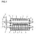
- eight kneading bars 4 are arranged on the main shaft 2, distributed over the circumference of the main shaft 2.
- only two kneading bars 4 are arranged on the cleaning shaft 3 distributed over the circumference.
- the kneading bars 4 are preferably U-shaped and engage - as in FIG. 1 shown - on the side at which the cleaning shaft 3 and the main shaft 2 are adjacent to each other. As a result, by the cleaning shaft 3, the material which accumulates on the main shaft between the webs, removed.
- 8 kneading bars 4 are arranged distributed over the circumference on the main shaft and on the cleaning shaft 2 two kneading bars 4, the cleaning shaft 3 rotates four times as fast as the main shaft 2. This ensures that the kneading 4 of the Putzwelle 3 engage in all kneading 4 of the main shaft 2.
- any other combination of kneading 4 on cleaning shaft 3 and main shaft 2 is conceivable.
- the speed ratio of main shaft 2 is set to cleaning shaft 3.
- the main shaft 2 and the cleaning shaft 3 are enclosed by a housing 6.
- the housing 6 is preferably designed with a double jacket. As a result, a gap 7 is formed in the housing, which can be flowed through by a temperature control medium.
- the shafts are preferably driven by a motor 8 and a gear 9.
- the speed of the waves 2, 3 is defined.
- the main shaft 2 and the cleaning shaft 3 rotate at different speeds, it is also possible that the main shaft 2 and the cleaning shaft 3 rotate at the same speed, Furthermore, the main shaft 2 and the cleaning shaft 3 can be operated either in the same direction or in opposite directions.
- the housing 6 are above the main shaft 2 and the cleaning shaft 3 openings 10, which are shown here by dashed lines. Via the openings 10, reactants can be fed to the mixing kneader 1. It is also possible for the product produced in the mixing kneader 1 to be degassed via the openings 10.
- an opening 11 is formed in the housing 6.
- the opening 11 for product removal is preferably arranged on the side of the cleaning shaft 3, but may also be arranged on the side of the main shaft 2.
- a temperature control medium For cooling the main shaft 2 and the cleaning shaft 3, these are flowed through by a temperature control medium.
- the arrows denoted by reference numeral 12 show the point at which the temperature control of the main shaft 2 and 3 Putzwelle is supplied.
- the temperature control medium is withdrawn again from the main shaft 2 or plaster shaft 3.
- a temperature control of the waves 2, 3 in the DC is possible.
- the temperature control medium is dispensed counter to the direction of the arrow at the point designated by reference numeral 13 and removed at the point designated by reference numeral 12.
- FIG. 2 shows a section through a housing portion of an inventively designed mixing kneader in the region of the opening for product removal.
- the housing 6 preferably designed as a hollow shaft cleaning shaft 3 and main shaft 2 are added.
- the Eduktzussel takes place via the openings 10 above the waves 2, 3, which are preferably designed as streams 20.
- the opening 11 is formed in the housing.
- the opening 11 is partially closed by a weir 14.
- the end edge 21 of the weir 14, which simultaneously forms the lower edge of the discharge opening is preferably arranged at an angle ⁇ to the vertical in the range of 30 to 55 °.
- the opening angle ⁇ of the product removal opening is preferably in the range of 10 to 20 °.
- the cross-sectional area of the product removal port may be adjusted by a flap 15.
- the flap 15 at the in FIG. 2 illustrated embodiment in axially displaceable.
- the movement of the flap 15 takes place via a drive 16.
- the degree of filling in the mixing kneader 1 is set via the cross-sectional area of the opening for product removal. The smaller the opening cross-section, the greater the degree of filling with the same product and constant speed.
- FIG. 2 illustrated embodiment is located in the lower part of the weir 14 an emptying flap 17.
- the emptying flap 17 is actuated by means of a handwheel 19 via a spindle 18.
- the open position of the discharge flap 17 is shown in dashed lines.
- the discharge flap 17 may be arranged at any other position in the housing 6.
- the emptying flap 17 is preferably arranged on the product removal side in the housing 6.
- the weir 14 and thus the opening for product removal and the discharge flap 17 can be arranged either on the side of the cleaning shaft 3 or on the side of the main shaft 2 in the housing 6.
- FIG. 3 shows a plan view of the weir and the opening for product removal.
- the discharge flap 17 is formed in the weir 14.
- the emptying flap 17 is actuated via the handwheel 19.
- the weir 14 closes an opening in the housing 6 so far that only the opening for product removal 22 remains free.
- the opening for product removal 22 is located in the upper third of the housing 6.
- the opening for product removal 22 can be further closed by the flap 15 in the embodiment shown here, whereby the opening cross-section is reduced.
- the flap 15 is driven by the output 16.
- the opening cross-section of the product removal opening 22 can also be adjusted by a flap movable in the tangential direction.
- the tangential Flap can either close the opening from above.
- the end edge 21 of the weir 14 can be displaced in the direction of the opening for product removal 22 and thus reduce the opening cross-section of the opening for product removal 22.
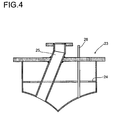
- a displacer 23 is shown, with which the opening 10 can be closed.
- the displacer 23 is placed in the dome 20 and preferably screwed via a flange with this.
- the displacer 23 is preferably formed as a hollow body.
- an annular circumferential rib 24 is arranged in the displacer 23.
- a channel 25 is formed in the displacer 23 in a preferred embodiment. Via the channel 25, either solid or liquid educts can be fed to the mixing kneader 1. At the in FIG. 4 shown orientation of the channel 25, the starting materials are fed above one of the waves.
- the channel 25 extends perpendicularly in the displacer 23.
- the point of addition can also be arranged centrally between the waves.
- a further channel 26 can also be accommodated in the displacer 23, which has a smaller cross-section compared to the channel 25.
- the position at which the further channel 26 opens into the mixing kneader is preferably close to the mouth position of the channel 25.
- the channel 25 and the further channel 26 are provided with a plastic surface.
Landscapes
- Chemical & Material Sciences (AREA)
- Chemical Kinetics & Catalysis (AREA)
- Engineering & Computer Science (AREA)
- Mechanical Engineering (AREA)
- Organic Chemistry (AREA)
- Mixers Of The Rotary Stirring Type (AREA)
- Processing And Handling Of Plastics And Other Materials For Molding In General (AREA)
- Accessories For Mixers (AREA)
- Addition Polymer Or Copolymer, Post-Treatments, Or Chemical Modifications (AREA)
Abstract
Claims (22)
- Procédé pour la production de poly(méth)acrylates, qui peut être effectué en continu pendant une assez longue durée dans un malaxeur-mélangeur qui comprend au moins deux axes (2, 3) sur les surfaces desquels des barres de malaxage (4) sont disposées sur des montants (5) et qui sont entourés d'un carter (6), dans le malaxeur-mélangeur au moins un orifice (10) étant ménagé au-dessus des arbres et au moins un orifice (11) étant prévu pour la décharge du produit, les arbres (2, 3) étant placés de manière à pouvoir tourner au moins aisément aux deux extrémités et étant entraînés à au moins une extrémité, caractérisé en ce que le degré de remplissage à l'intérieur du malaxeur-mélangeur est ajusté, par réglage de la section transversale de l'ouverture de l'orifice (11) configuré en tant que déversoir dans la paroi du carter pour la décharge du produit pendant le fonctionnement, à vitesse constante de rotation des arbres et pour le même produit, de manière à éviter par une fragmentation suffisante du produit la formation d'agglomérats à partir de dépôts dans des zones mortes.
- Procédé selon la revendication 1, caractérisé en ce qu'en outre il comprend au moins l'une des étapes suivantes :(a) au moins un arbre sous forme d'arbre creux est traversé par un milieu de régulation thermique, l'entrée (12) pour le milieu de régulation thermique étant placée sur un côté de l'arbre et la sortie (13) étant placée sur l'autre,(b) ledit au moins un orifice au-dessus des arbres est fermé par un dispositif de déplacement (23) dont la face tournée vers les arbres est conçue de telle façon qu'entre le dispositif de déplacement (23) et les barres de malaxage des arbres est présent un espace dont l'écartement correspond au maximum à l'écartement constant qui se trouve entre barres de malaxage et carter.
- Procédé selon la revendication 2, caractérisé en ce que la section transversale d'ouverture de l'orifice (11) pour la décharge du produit est réglée pendant le fonctionnement par un volet (15) coulissant en direction axiale.
- Procédé selon la revendication 2, caractérisé en ce que la section transversale d'ouverture de l'orifice (11) pour la décharge du produit est réglée pendant le fonctionnement par un volet coulissant en direction tangentielle.
- Procédé selon la revendication 2, caractérisé en ce que la hauteur d'un déversoir (14) formant l'orifice (11) pour la décharge du produit est réglée pendant le fonctionnement par déplacement tangentiel du déversoir.
- Procédé selon l'une quelconque des revendications 1 à 5, caractérisé en ce que le milieu de régulation thermique est envoyé à contre-courant.
- Procédé selon l'une quelconque des revendications 1 à 6, caractérisé en ce que lors d'un arrêt ou avant un arrêt le malaxeur-mélangeur est vidé par un clapet de vidange.
- Procédé selon l'une quelconque des revendications 1 à 7, caractérisé en ce que le malaxeur-mélangeur est préchauffé avant l'introduction des produits de départ.
- Procédé selon l'une quelconque des revendications 1 à 8, caractérisé en ce que des monomères sont d'abord introduits en tant que produits de départ dans le malaxeur-mélangeur et à la position à laquelle 99,5 % des monomères sont convertis en le polymère, d'autres composants sont introduits sous forme de particules de matière solide.
- Procédé selon la revendication 9, caractérisé en ce que les particules de matière solide ont une taille maximale de particule de 500 µm, de préférence de 300 µm.
- Procédé selon l'une quelconque des revendications 1 à 10, caractérisé en ce que les arbres sont refroidis pendant le fonctionnement du malaxeur-mélangeur.
- Procédé selon la revendication 11, caractérisé en ce que pour le refroidissement les arbres sont traversés par un milieu de régulation thermique ayant une température d'au maximum 80 °C, de préférence d'au maximum 40 °C et en particulier d'au maximum 20 °C.
- Malaxeur-mélangeur, comprenant au moins deux axes (2, 3) sur les surfaces desquels des barres de malaxage (4) sont disposées sur des montants (5) et qui sont entourés d'un carter (6), dans lequel au moins un orifice (10) est ménagé au-dessus des arbres et au moins un orifice (11) est prévu pour la décharge du produit, les arbres (2, 3) étant placés de manière à pouvoir tourner au moins aisément aux deux extrémités et étant entraînés à au moins une extrémité,
caractérisé en ce que, pour l'ajustement du degré de remplissage à l'intérieur du malaxeur-mélangeur, la section transversale de l'ouverture de l'orifice (11) pour la décharge du produit est réglable pendant le fonctionnement, l'orifice pour la décharge du produit étant configuré en tant que déversoir (14) dans la paroi du carter. - Malaxeur-mélangeur selon la revendication 13, caractérisé en ce que de surcroît au moins l'une des caractéristiques suivantes est assurée(a) la construction des arbres est effectuée de manière que les propres fréquences de flexion de l'arbre présentent un écart d'au moins 5 %, de préférence d'au moins 15 % et en particulier d'au moins 20 % par rapport aux fréquences excitatrices,(b) au moins un arbre est conçu sous forme d'arbre creux et traversé par un milieu de régulation thermique, l'entrée (12) étant placée sur un côté de l'arbre et la sortie (13) étant placée sur l'autre,(b) ledit au moins un orifice au-dessus des arbres est fermé par un dispositif de déplacement (23) dont la face tournée vers les arbres est conçue de telle façon qu'entre le dispositif de déplacement (23) et les barres de malaxage des arbres est présent un espace dont l'écartement correspond au maximum à l'écartement constant qui se trouve entre barres de malaxage et carter.
- Malaxeur-mélangeur selon la revendication 13 ou 14, caractérisé en ce que l'orifice au-dessus des arbres est configuré sous forme de dôme (20) dans le carter.
- Malaxeur-mélangeur selon l'une quelconque des revendications 13 à 15, caractérisé en ce qu'à l'orifice pour la décharge du produit fait suite un couloir d'écoulement, dont les parois sont munies d'une isolation.
- Malaxeur-mélangeur selon l'une quelconque des revendications 13 à 16, caractérisé en ce que le malaxeur-mélangeur comprend un clapet mobile de vidange (17) supplémentaire, ayant une section transversale d'ouverture d'au moins 10 000 mm2.
- Malaxeur-mélangeur selon la revendication 17, caractérisé en ce que le clapet de vidange (17) est constitué dans le déversoir (14).
- Malaxeur-mélangeur selon l'une quelconque des revendications 13 à 18, caractérisé en ce qu'au moins un canal (25, 26) pour l'introduction des produits de départ est constitué dans le déversoir (23).
- Malaxeur-mélangeur selon la revendication 19, caractérisé en ce qu'un dispositif doseur pour l'introduction des produits de départ est placé dans le canal (25).
- Malaxeur-mélangeur selon la revendication 19 ou 20, caractérisé en ce que ledit au moins un canal (25, 26) présente une surface en matière plastique.
- Malaxeur-mélangeur selon l'une quelconque des revendications 19 à 21, caractérisé en ce que dans le cas d'au moins deux canaux (25, 26) dans le déversoir, des orifices des canaux, tournés vers les arbres, sont disposés à proximité les uns des autres.
Priority Applications (2)
| Application Number | Priority Date | Filing Date | Title |
|---|---|---|---|
| EP08170459A EP2052773B1 (fr) | 2004-09-28 | 2005-09-28 | Malaxeur-mélangeur et utilisation du malaxeur-mélangeur pour la fabrication de poly(méth)acrylates |
| EP10186094A EP2275197B1 (fr) | 2004-09-28 | 2005-09-28 | Malaxeur-mélangeur et procédé de fabrication de poly(méth)acrylates en utilisant le malaxeur-mélangeur |
Applications Claiming Priority (2)
| Application Number | Priority Date | Filing Date | Title |
|---|---|---|---|
| DE102004047430 | 2004-09-28 | ||
| PCT/EP2005/010469 WO2006034853A1 (fr) | 2004-09-28 | 2005-09-28 | Malaxeur et procede de production de poy(meth)acrylates utilisant ce malaxeur |
Related Child Applications (1)
| Application Number | Title | Priority Date | Filing Date |
|---|---|---|---|
| EP08170459A Division EP2052773B1 (fr) | 2004-09-28 | 2005-09-28 | Malaxeur-mélangeur et utilisation du malaxeur-mélangeur pour la fabrication de poly(méth)acrylates |
Publications (2)
| Publication Number | Publication Date |
|---|---|
| EP1796823A1 EP1796823A1 (fr) | 2007-06-20 |
| EP1796823B1 true EP1796823B1 (fr) | 2009-07-22 |
Family
ID=35431579
Family Applications (3)
| Application Number | Title | Priority Date | Filing Date |
|---|---|---|---|
| EP05793749A Active EP1796823B1 (fr) | 2004-09-28 | 2005-09-28 | Malaxeur et procede de production de poy(meth)acrylates utilisant ce malaxeur |
| EP08170459A Active EP2052773B1 (fr) | 2004-09-28 | 2005-09-28 | Malaxeur-mélangeur et utilisation du malaxeur-mélangeur pour la fabrication de poly(méth)acrylates |
| EP10186094A Active EP2275197B1 (fr) | 2004-09-28 | 2005-09-28 | Malaxeur-mélangeur et procédé de fabrication de poly(méth)acrylates en utilisant le malaxeur-mélangeur |
Family Applications After (2)
| Application Number | Title | Priority Date | Filing Date |
|---|---|---|---|
| EP08170459A Active EP2052773B1 (fr) | 2004-09-28 | 2005-09-28 | Malaxeur-mélangeur et utilisation du malaxeur-mélangeur pour la fabrication de poly(méth)acrylates |
| EP10186094A Active EP2275197B1 (fr) | 2004-09-28 | 2005-09-28 | Malaxeur-mélangeur et procédé de fabrication de poly(méth)acrylates en utilisant le malaxeur-mélangeur |
Country Status (7)
| Country | Link |
|---|---|
| US (2) | US8070351B2 (fr) |
| EP (3) | EP1796823B1 (fr) |
| JP (2) | JP4881309B2 (fr) |
| CN (2) | CN102091551B (fr) |
| DE (1) | DE502005007757D1 (fr) |
| TW (1) | TW200626227A (fr) |
| WO (1) | WO2006034853A1 (fr) |
Families Citing this family (41)
| Publication number | Priority date | Publication date | Assignee | Title |
|---|---|---|---|---|
| GB9715857D0 (en) * | 1997-07-29 | 1997-10-01 | Philips Electronics Nv | Wireless networked message routing |
| DE502005007757D1 (de) * | 2004-09-28 | 2009-09-03 | Basf Se | Mischkneter sowie verfahren zur herstellung von poly(meth)acrylaten unter verwendung des mischkneters |
| ES2314973T3 (es) * | 2006-02-06 | 2009-03-16 | Buss Ag | Mezcladora y amasadora. |
| ATE465188T1 (de) * | 2006-10-19 | 2010-05-15 | Basf Se | Verfahren zur herstellung von superabsorbern |
| US7674492B2 (en) * | 2006-10-23 | 2010-03-09 | Wenger Manufacturing, Inc. | Preconditioner having independently driven high-speed mixer shafts |
| CN101959538A (zh) * | 2008-03-05 | 2011-01-26 | 巴斯夫欧洲公司 | 制备超吸收剂的方法 |
| JP4355354B2 (ja) * | 2008-03-18 | 2009-10-28 | 株式会社神戸製鋼所 | 二軸混練押出機 |
| DE102008048580B4 (de) * | 2008-09-23 | 2014-08-21 | List Holding Ag | Vorrichtung zur Durchführung von mechanischen, chemischen und/oder thermischen Prozessen |
| WO2010100936A1 (fr) | 2009-03-04 | 2010-09-10 | 株式会社日本触媒 | Procédé de production d'une résine absorbant l'eau |
| CN104974358B (zh) | 2009-03-31 | 2018-11-23 | 株式会社日本触媒 | 颗粒状吸水性树脂的制造方法 |
| EP2353707B1 (fr) * | 2010-01-28 | 2013-08-28 | Bühler AG | Dispositif et procédé pour la malaxage et le pétrissage de pâtes, particulièrement de pâtes de chocolat |
| US8765906B2 (en) | 2010-04-27 | 2014-07-01 | Nippon Shokubai, Co., Ltd. | Method for producing polyacrylic acid (salt) type water absorbent resin powder |
| CN103561781B (zh) * | 2011-05-26 | 2016-06-29 | 巴斯夫欧洲公司 | 连续制备吸水性聚合物颗粒的方法 |
| JP2013010083A (ja) * | 2011-06-30 | 2013-01-17 | Shin Nichinan:Kk | 混練装置 |
| JP5551836B2 (ja) | 2011-11-16 | 2014-07-16 | 株式会社日本触媒 | ポリアクリル酸(塩)系吸水性樹脂の製造方法 |
| US10539191B2 (en) * | 2011-11-16 | 2020-01-21 | List Technology Ag | Process for connecting functional elements to a shaft |
| EP2846903B1 (fr) | 2012-05-07 | 2016-10-19 | Basf Se | Procédé pour faire fonctionner un mélangeur-malaxeur |
| US9415529B2 (en) * | 2012-05-08 | 2016-08-16 | Basf Se | Method for operating an apparatus with at least one rotating shaft |
| US10197536B2 (en) | 2012-05-11 | 2019-02-05 | Basf Se | Method for detecting damage to a hollow shaft |
| EP2847584B1 (fr) | 2012-05-11 | 2018-01-03 | Basf Se | Procédé de détection de détériorations sur un arbre creux |
| CN104364269B (zh) | 2012-06-13 | 2016-10-12 | 巴斯夫欧洲公司 | 在装有至少两个轴向平行旋转轴的聚合反应器中制备吸水性聚合物颗粒的方法 |
| US9248429B2 (en) | 2012-06-13 | 2016-02-02 | Basf Se | Process for producing water-absorbing polymer particles in a polymerization reactor with at least two axially parallel rotating shafts |
| CN103372926A (zh) * | 2012-11-23 | 2013-10-30 | 无锡众望四维科技有限公司 | 过渡舱 |
| US20140151481A1 (en) * | 2012-12-03 | 2014-06-05 | Basf Se | Process for Connecting Functional Elements to a Shelf |
| US9822203B2 (en) | 2013-01-29 | 2017-11-21 | Basf Se | Method for producing water-absorbing polymer particles with high swelling rate and high centrifuge retention capacity with simultaneously high permeability of the swollen gel bed |
| CN107075030B (zh) | 2014-05-08 | 2020-08-04 | 巴斯夫欧洲公司 | 制备吸水性聚合物颗粒的方法 |
| US20190003789A1 (en) | 2015-12-23 | 2019-01-03 | Basf Se | Heat exchanger for heating gas and use of the heat exchanger |
| DE102016108108A1 (de) * | 2016-05-02 | 2017-11-02 | Marco Systemanalyse Und Entwicklung Gmbh | Vorrichtung und verfahren zum mischen von komponenten |
| CN106908100A (zh) * | 2017-03-16 | 2017-06-30 | 西安近代化学研究所 | 一种捏合机整场参数测试装置 |
| CN107051357A (zh) * | 2017-04-10 | 2017-08-18 | 山东里德工程技术有限公司 | 双轴自清洁反应器 |
| CN108619936B (zh) * | 2018-03-05 | 2020-11-13 | 青岛伊诺威能源化工新技术有限公司 | 内加热式搅拌器及其热解室与固体有机物热解装置 |
| MX2021004421A (es) | 2018-10-18 | 2021-07-06 | Basf Se | Proceso de fracturamiento de formaciones subterraneas. |
| MX2021004422A (es) | 2018-10-18 | 2021-07-06 | Basf Se | Metodo para proporcionar concentrados acuosos homogeneos de poliacrilamida y su uso. |
| US20220003679A1 (en) | 2018-11-29 | 2022-01-06 | Basf Se | Prediction of physical properties of superabsorbent polymers |
| KR20210062459A (ko) * | 2019-11-21 | 2021-05-31 | 주식회사 엘지화학 | 고흡수성 함수겔 복합 세절 장치 |
| WO2021209149A1 (fr) | 2020-04-17 | 2021-10-21 | Basf Se | Procédé et dispositifs de production de fluides aqueux de traitement de puits de forage |
| WO2021209150A1 (fr) | 2020-04-17 | 2021-10-21 | Basf Se | Procédés et dispositifs permettant la production de fluides aqueux de traitement de puits de forage |
| WO2021209148A1 (fr) | 2020-04-17 | 2021-10-21 | Basf Se | Processus de fabrication de liquide d'injection aqueux |
| EP4063091A1 (fr) * | 2021-03-26 | 2022-09-28 | Starlinger & Co Gesellschaft m.b.H. | Dispositif et procédé de traitement thermique des fusions en matière thermoplastique |
| CN114272789A (zh) * | 2021-12-21 | 2022-04-05 | 浙江大学 | 一种用于聚酯终缩聚的卧式双轴自清洁搅拌设备 |
| WO2023156293A1 (fr) | 2022-02-17 | 2023-08-24 | Basf Se | Procédé et dispositif améliorés de fabrication de fluides de traitement aqueux de puits de forage |
Family Cites Families (56)
| Publication number | Priority date | Publication date | Assignee | Title |
|---|---|---|---|---|
| US1851388A (en) * | 1932-03-29 | H h hackstedde | ||
| US1418642A (en) * | 1921-05-25 | 1922-06-06 | Morgan & Wright | Mixing machine |
| US2121486A (en) * | 1937-01-22 | 1938-06-21 | Glen G Merchen | Hopper and agitator |
| US2368102A (en) * | 1942-10-05 | 1945-01-30 | Bowman Gum Inc | Apparatus and method for the treatment of rubber of rubberlike materials |
| US2504337A (en) * | 1946-08-29 | 1950-04-18 | Evarts G Loomis | Mixing machine for plastic materials |
| NL123955C (fr) * | 1959-07-03 | 1900-01-01 | ||
| US3239878A (en) * | 1962-05-15 | 1966-03-15 | Farrel Corp | Continuous internal stiff-gel mixer |
| GB1053931A (fr) * | 1964-07-24 | 1900-01-01 | ||
| US3332368A (en) * | 1965-12-21 | 1967-07-25 | Marion Corp | Continuous dough mixer |
| US3463459A (en) * | 1968-02-12 | 1969-08-26 | Baker Perkins Inc | Automatically operated door mechanism for a mixer,kneader,reactor or like machine |
| US3561046A (en) * | 1968-03-05 | 1971-02-09 | Usm Corp | Lubricated discharge orifice for restraining plastic flow |
| CH506322A (de) * | 1969-03-17 | 1971-04-30 | List Heinz | Mehrspindelige Misch- und Knetmaschine |
| US3951389A (en) * | 1972-11-17 | 1976-04-20 | The B. F. Goodrich Company | Elastomer processing method |
| JPS5248909B2 (fr) * | 1972-11-17 | 1977-12-13 | ||
| FR2213933B1 (fr) * | 1973-01-16 | 1976-05-14 | Rhone Poulenc Ind | |
| CA1062502A (fr) * | 1975-04-17 | 1979-09-18 | John P. Porter | Systeme de saisie des donnees pour appareil de traitement d'elastomeres |
| CH596876A5 (fr) * | 1975-09-01 | 1978-03-31 | Thyssen Industrie | |
| SU958108A1 (ru) * | 1981-02-12 | 1982-09-15 | Ленинградский Ордена Октябрьской Революции И Ордена Трудового Красного Знамени Технологический Институт Им.Ленсовета | Резиносмеситель |
| EP0084426A3 (fr) * | 1982-01-16 | 1983-08-03 | Francis Shaw Plc | Dispositif de mélange |
| US4542992A (en) * | 1984-10-17 | 1985-09-24 | Usm Corporation | Continuous mixer |
| JPS61234917A (ja) * | 1985-04-10 | 1986-10-20 | Mitsubishi Heavy Ind Ltd | 表面更新性を有する横型反応器 |
| JPS61266206A (ja) * | 1985-05-20 | 1986-11-25 | Kobe Steel Ltd | 連続混練機の混練制御装置 |
| US4681457A (en) * | 1985-05-14 | 1987-07-21 | Kabushiki Kaisha Kobe Seiko Sho | Continuous mixer |
| JPS61263711A (ja) * | 1985-05-14 | 1986-11-21 | Kobe Steel Ltd | 2軸形連続混練機 |
| JPS61261008A (ja) * | 1985-05-15 | 1986-11-19 | Kobe Steel Ltd | バツチ型混練機 |
| DE3621429A1 (de) * | 1985-07-02 | 1987-01-08 | Milchem Inc | Kontinuierliches polymerisationsverfahren |
| JPS62172179A (ja) * | 1986-01-25 | 1987-07-29 | 株式会社クボタ | ら旋搬送式乾燥機 |
| CH674318A5 (fr) * | 1987-08-28 | 1990-05-31 | List Ag | |
| CH678285A5 (fr) * | 1988-02-16 | 1991-08-30 | List Ag | |
| CH680196A5 (fr) * | 1988-02-16 | 1992-07-15 | List Ag | |
| DE4118884A1 (de) | 1991-06-07 | 1992-12-10 | List Ag | Mischkneter |
| US5382089A (en) * | 1991-06-07 | 1995-01-17 | Farrel Corporation | Convenient access for clean-out and maintenance of mixing chamber and both rotors in two-rotor continuous mixers for plastic materials |
| CA2102577A1 (fr) * | 1992-11-24 | 1994-05-25 | Walther Schwenk | Melangeur-malaxeur |
| CH695764A5 (de) * | 1992-12-31 | 2006-08-31 | Antogi Ag | Doppelschneckenpresse. |
| JPH06218260A (ja) * | 1993-01-26 | 1994-08-09 | Hitachi Ltd | 高粘性物質の連続処理装置 |
| JP2749511B2 (ja) * | 1994-02-22 | 1998-05-13 | 株式会社栗本鐵工所 | スクリュー型加熱装置 |
| JPH07303847A (ja) | 1994-05-13 | 1995-11-21 | Densen Sogo Gijutsu Center | 熱可塑性樹脂の粉砕方法 |
| JP3568163B2 (ja) * | 1994-07-18 | 2004-09-22 | 日工株式会社 | 二軸式ミキサ |
| US5492403A (en) * | 1995-03-13 | 1996-02-20 | The Goodyear Tire & Rubber Company | Drop door control for internal mixer |
| DE19536944A1 (de) | 1995-10-04 | 1997-04-10 | List Ag | Mischkneter |
| JPH11106406A (ja) * | 1997-09-30 | 1999-04-20 | Mitsui Chem Inc | 反応器 |
| SE513362C2 (sv) * | 1997-11-18 | 2000-09-04 | Borealis As | Förfarande för minskning av reaktornedsmutsning |
| JP2000065062A (ja) | 1998-08-12 | 2000-03-03 | Seiko Seiki Co Ltd | 磁気軸受装置の回転体共振抑制装置 |
| JP2000202266A (ja) * | 1999-01-18 | 2000-07-25 | Nikko Co Ltd | 連続式ミキサ及びその混練方法 |
| DE19955861A1 (de) | 1999-11-20 | 2001-05-23 | Basf Ag | Verfahren zur kontinuierlichen Herstellung von vernetzten feinteiligen gelförmigen Polymerisaten |
| JP2002039177A (ja) | 2000-07-24 | 2002-02-06 | Ntn Corp | 非接触軸受スピンドル装置 |
| JP4406534B2 (ja) * | 2001-01-29 | 2010-01-27 | 東洋エンジニアリング株式会社 | 反応器 |
| CA2445074A1 (fr) * | 2001-04-25 | 2002-11-14 | List Ag | Barres melangeuses a effet nettoyant dans le sens radial ou axial |
| BR0212696B1 (pt) | 2001-09-12 | 2013-02-05 | processo contÍnuo de polimerizaÇço para a preparaÇço de polÍmeros absorventes de Água, insoléveis em Água. | |
| DE10150900C1 (de) * | 2001-10-18 | 2003-04-24 | List Ag | Mischkneter mit unterschiedlich dicken Tragelementen für Knetbarren |
| JP4112908B2 (ja) * | 2002-06-07 | 2008-07-02 | 株式会社日立プラントテクノロジー | 連続攪拌装置及び重縮合系樹脂の連続重縮合方法 |
| US7398606B2 (en) | 2002-09-04 | 2008-07-15 | List Ag | Process for the production of SAP |
| JP4102713B2 (ja) * | 2003-06-17 | 2008-06-18 | 株式会社神戸製鋼所 | 連続混練装置およびその運転方法 |
| DE502005007757D1 (de) * | 2004-09-28 | 2009-09-03 | Basf Se | Mischkneter sowie verfahren zur herstellung von poly(meth)acrylaten unter verwendung des mischkneters |
| JP5479329B2 (ja) * | 2007-06-11 | 2014-04-23 | ビーエーエスエフ ソシエタス・ヨーロピア | シャフトの過負荷を回避する方法 |
| EP2846903B1 (fr) * | 2012-05-07 | 2016-10-19 | Basf Se | Procédé pour faire fonctionner un mélangeur-malaxeur |
-
2005
- 2005-09-28 DE DE502005007757T patent/DE502005007757D1/de active Active
- 2005-09-28 US US11/663,753 patent/US8070351B2/en active Active
- 2005-09-28 EP EP05793749A patent/EP1796823B1/fr active Active
- 2005-09-28 CN CN2010105780618A patent/CN102091551B/zh active Active
- 2005-09-28 WO PCT/EP2005/010469 patent/WO2006034853A1/fr active Application Filing
- 2005-09-28 EP EP08170459A patent/EP2052773B1/fr active Active
- 2005-09-28 CN CN2005800405454A patent/CN101065179B/zh active Active
- 2005-09-28 JP JP2007532859A patent/JP4881309B2/ja active Active
- 2005-09-28 TW TW094133756A patent/TW200626227A/zh unknown
- 2005-09-28 EP EP10186094A patent/EP2275197B1/fr active Active
-
2011
- 2011-09-26 JP JP2011209542A patent/JP2012055887A/ja active Pending
- 2011-10-28 US US13/284,012 patent/US20120071613A1/en not_active Abandoned
Also Published As
| Publication number | Publication date |
|---|---|
| EP1796823A1 (fr) | 2007-06-20 |
| EP2052773A3 (fr) | 2009-05-06 |
| EP2052773A2 (fr) | 2009-04-29 |
| JP4881309B2 (ja) | 2012-02-22 |
| WO2006034853A1 (fr) | 2006-04-06 |
| JP2012055887A (ja) | 2012-03-22 |
| EP2052773B1 (fr) | 2012-07-18 |
| EP2275197B1 (fr) | 2013-04-03 |
| CN102091551B (zh) | 2013-07-17 |
| US20120071613A1 (en) | 2012-03-22 |
| CN101065179B (zh) | 2011-02-02 |
| TW200626227A (en) | 2006-08-01 |
| EP2275197A1 (fr) | 2011-01-19 |
| CN102091551A (zh) | 2011-06-15 |
| CN101065179A (zh) | 2007-10-31 |
| JP2008514396A (ja) | 2008-05-08 |
| DE502005007757D1 (de) | 2009-09-03 |
| US8070351B2 (en) | 2011-12-06 |
| US20080080300A1 (en) | 2008-04-03 |
Similar Documents
| Publication | Publication Date | Title |
|---|---|---|
| EP1796823B1 (fr) | Malaxeur et procede de production de poy(meth)acrylates utilisant ce malaxeur | |
| EP1901839B1 (fr) | Utilisation d'un dispositif pour ajouter au moins un additif dans un compartiment interieur d'un reacteur | |
| EP1237937B1 (fr) | Procede de preparation continue de polymerisats geliformes reticules a fines particules | |
| DE69630441T3 (de) | Wasser-Absorbierungsmittel und Verfahren und Vorrichtung zu dessen Herstellung | |
| WO2005122075A1 (fr) | Procede pour produire des polymeres hydrophiles et produits de post-traitement les contenant, par utilisation d'un modele produit par ordinateur | |
| EP1086143B1 (fr) | Procede et dispositif pour la production en continu de polymeres | |
| EP1326898B1 (fr) | Polymere reticule, gonflant dans l'eau et son procede de preparation | |
| DE2625149B2 (de) | Verfahren und Vorrichtung zur kontinuierlichen Herstellung von Vinylchloridpolymerisaten in wäßriger Emulsion | |
| EP1756204A1 (fr) | Procede de production d'un polymere absorbant par sechage avec etalement | |
| EP2900358B1 (fr) | Mélangeur-pétrisseur de mise en oeuvre des procédés mécaniques, chimiques et/ou thermiques | |
| EP0865821A1 (fr) | Usage d'un agitateur de plusiers etages pour la production de polymèrisats | |
| DE2759878C2 (de) | Vorrichtung zur Verarbeitung von polymerem Material, insbesondere von festem und viskosem Kunststoff | |
| EP2846903B1 (fr) | Procédé pour faire fonctionner un mélangeur-malaxeur | |
| WO2003008175A1 (fr) | Procede et dispositif pour la production en continu de melanges de caoutchouc | |
| DE102004001599A1 (de) | Verfahren zur Herstellung von Schmelzpolymerisaten im Rohrreaktor | |
| DE4333876C2 (de) | Verfahren für Altteile bzw. Abfälle aus Kunststoff, insbesondere aus aufgeschäumtem Kunststoff | |
| DD141975A3 (de) | Verfahren und vorrichtung zur kontinuierlichen herstellung von polyurethanprodukten | |
| DE19809219A1 (de) | Verfahren zur kontinuierlichen Herstellung von Polymerdispersionen durch wässrige Emulsionspolymerisation | |
| DE1779291B1 (de) | Verfahren und vorrichtung zum herstellen von kunststoffschaum | |
| DE102009007640A1 (de) | Verfahren zur kontinuierlichen Behandlung eines zähviskosen, pastösen Produktes |
Legal Events
| Date | Code | Title | Description |
|---|---|---|---|
| PUAI | Public reference made under article 153(3) epc to a published international application that has entered the european phase |
Free format text: ORIGINAL CODE: 0009012 |
|
| 17P | Request for examination filed |
Effective date: 20070502 |
|
| AK | Designated contracting states |
Kind code of ref document: A1 Designated state(s): AT BE BG CH CY CZ DE DK EE ES FI FR GB GR HU IE IS IT LI LT LU LV MC NL PL PT RO SE SI SK TR |
|
| 17Q | First examination report despatched |
Effective date: 20071108 |
|
| DAX | Request for extension of the european patent (deleted) | ||
| RAP1 | Party data changed (applicant data changed or rights of an application transferred) |
Owner name: BASF SE |
|
| GRAP | Despatch of communication of intention to grant a patent |
Free format text: ORIGINAL CODE: EPIDOSNIGR1 |
|
| GRAS | Grant fee paid |
Free format text: ORIGINAL CODE: EPIDOSNIGR3 |
|
| GRAA | (expected) grant |
Free format text: ORIGINAL CODE: 0009210 |
|
| AK | Designated contracting states |
Kind code of ref document: B1 Designated state(s): AT BE BG CH CY CZ DE DK EE ES FI FR GB GR HU IE IS IT LI LT LU LV MC NL PL PT RO SE SI SK TR |
|
| REG | Reference to a national code |
Ref country code: GB Ref legal event code: FG4D Free format text: NOT ENGLISH |
|
| REG | Reference to a national code |
Ref country code: CH Ref legal event code: EP |
|
| REG | Reference to a national code |
Ref country code: IE Ref legal event code: FG4D |
|
| REF | Corresponds to: |
Ref document number: 502005007757 Country of ref document: DE Date of ref document: 20090903 Kind code of ref document: P |
|
| NLV1 | Nl: lapsed or annulled due to failure to fulfill the requirements of art. 29p and 29m of the patents act | ||
| PG25 | Lapsed in a contracting state [announced via postgrant information from national office to epo] |
Ref country code: LT Free format text: LAPSE BECAUSE OF FAILURE TO SUBMIT A TRANSLATION OF THE DESCRIPTION OR TO PAY THE FEE WITHIN THE PRESCRIBED TIME-LIMIT Effective date: 20090722 Ref country code: ES Free format text: LAPSE BECAUSE OF FAILURE TO SUBMIT A TRANSLATION OF THE DESCRIPTION OR TO PAY THE FEE WITHIN THE PRESCRIBED TIME-LIMIT Effective date: 20091102 Ref country code: FI Free format text: LAPSE BECAUSE OF FAILURE TO SUBMIT A TRANSLATION OF THE DESCRIPTION OR TO PAY THE FEE WITHIN THE PRESCRIBED TIME-LIMIT Effective date: 20090722 Ref country code: IS Free format text: LAPSE BECAUSE OF FAILURE TO SUBMIT A TRANSLATION OF THE DESCRIPTION OR TO PAY THE FEE WITHIN THE PRESCRIBED TIME-LIMIT Effective date: 20091122 Ref country code: SE Free format text: LAPSE BECAUSE OF FAILURE TO SUBMIT A TRANSLATION OF THE DESCRIPTION OR TO PAY THE FEE WITHIN THE PRESCRIBED TIME-LIMIT Effective date: 20090722 |
|
| PG25 | Lapsed in a contracting state [announced via postgrant information from national office to epo] |
Ref country code: SI Free format text: LAPSE BECAUSE OF FAILURE TO SUBMIT A TRANSLATION OF THE DESCRIPTION OR TO PAY THE FEE WITHIN THE PRESCRIBED TIME-LIMIT Effective date: 20090722 Ref country code: LV Free format text: LAPSE BECAUSE OF FAILURE TO SUBMIT A TRANSLATION OF THE DESCRIPTION OR TO PAY THE FEE WITHIN THE PRESCRIBED TIME-LIMIT Effective date: 20090722 Ref country code: PL Free format text: LAPSE BECAUSE OF FAILURE TO SUBMIT A TRANSLATION OF THE DESCRIPTION OR TO PAY THE FEE WITHIN THE PRESCRIBED TIME-LIMIT Effective date: 20090722 Ref country code: NL Free format text: LAPSE BECAUSE OF FAILURE TO SUBMIT A TRANSLATION OF THE DESCRIPTION OR TO PAY THE FEE WITHIN THE PRESCRIBED TIME-LIMIT Effective date: 20090722 |
|
| REG | Reference to a national code |
Ref country code: IE Ref legal event code: FD4D |
|
| PG25 | Lapsed in a contracting state [announced via postgrant information from national office to epo] |
Ref country code: BG Free format text: LAPSE BECAUSE OF FAILURE TO SUBMIT A TRANSLATION OF THE DESCRIPTION OR TO PAY THE FEE WITHIN THE PRESCRIBED TIME-LIMIT Effective date: 20091022 Ref country code: PT Free format text: LAPSE BECAUSE OF FAILURE TO SUBMIT A TRANSLATION OF THE DESCRIPTION OR TO PAY THE FEE WITHIN THE PRESCRIBED TIME-LIMIT Effective date: 20091122 |
|
| PLBI | Opposition filed |
Free format text: ORIGINAL CODE: 0009260 |
|
| PG25 | Lapsed in a contracting state [announced via postgrant information from national office to epo] |
Ref country code: IE Free format text: LAPSE BECAUSE OF FAILURE TO SUBMIT A TRANSLATION OF THE DESCRIPTION OR TO PAY THE FEE WITHIN THE PRESCRIBED TIME-LIMIT Effective date: 20090722 Ref country code: RO Free format text: LAPSE BECAUSE OF FAILURE TO SUBMIT A TRANSLATION OF THE DESCRIPTION OR TO PAY THE FEE WITHIN THE PRESCRIBED TIME-LIMIT Effective date: 20090722 Ref country code: EE Free format text: LAPSE BECAUSE OF FAILURE TO SUBMIT A TRANSLATION OF THE DESCRIPTION OR TO PAY THE FEE WITHIN THE PRESCRIBED TIME-LIMIT Effective date: 20090722 Ref country code: CZ Free format text: LAPSE BECAUSE OF FAILURE TO SUBMIT A TRANSLATION OF THE DESCRIPTION OR TO PAY THE FEE WITHIN THE PRESCRIBED TIME-LIMIT Effective date: 20090722 Ref country code: DK Free format text: LAPSE BECAUSE OF FAILURE TO SUBMIT A TRANSLATION OF THE DESCRIPTION OR TO PAY THE FEE WITHIN THE PRESCRIBED TIME-LIMIT Effective date: 20090722 Ref country code: MC Free format text: LAPSE BECAUSE OF NON-PAYMENT OF DUE FEES Effective date: 20090930 |
|
| REG | Reference to a national code |
Ref country code: CH Ref legal event code: PL |
|
| 26 | Opposition filed |
Opponent name: LIST AG Effective date: 20100421 |
|
| PG25 | Lapsed in a contracting state [announced via postgrant information from national office to epo] |
Ref country code: SK Free format text: LAPSE BECAUSE OF FAILURE TO SUBMIT A TRANSLATION OF THE DESCRIPTION OR TO PAY THE FEE WITHIN THE PRESCRIBED TIME-LIMIT Effective date: 20090722 |
|
| PLAX | Notice of opposition and request to file observation + time limit sent |
Free format text: ORIGINAL CODE: EPIDOSNOBS2 |
|
| REG | Reference to a national code |
Ref country code: FR Ref legal event code: ST Effective date: 20100531 |
|
| PG25 | Lapsed in a contracting state [announced via postgrant information from national office to epo] |
Ref country code: FR Free format text: LAPSE BECAUSE OF NON-PAYMENT OF DUE FEES Effective date: 20090930 |
|
| PG25 | Lapsed in a contracting state [announced via postgrant information from national office to epo] |
Ref country code: GR Free format text: LAPSE BECAUSE OF FAILURE TO SUBMIT A TRANSLATION OF THE DESCRIPTION OR TO PAY THE FEE WITHIN THE PRESCRIBED TIME-LIMIT Effective date: 20091023 Ref country code: CH Free format text: LAPSE BECAUSE OF NON-PAYMENT OF DUE FEES Effective date: 20090930 Ref country code: LI Free format text: LAPSE BECAUSE OF NON-PAYMENT OF DUE FEES Effective date: 20090930 |
|
| PLAF | Information modified related to communication of a notice of opposition and request to file observations + time limit |
Free format text: ORIGINAL CODE: EPIDOSCOBS2 |
|
| PLAB | Opposition data, opponent's data or that of the opponent's representative modified |
Free format text: ORIGINAL CODE: 0009299OPPO |
|
| PG25 | Lapsed in a contracting state [announced via postgrant information from national office to epo] |
Ref country code: AT Free format text: LAPSE BECAUSE OF NON-PAYMENT OF DUE FEES Effective date: 20090928 Ref country code: GB Free format text: LAPSE BECAUSE OF NON-PAYMENT OF DUE FEES Effective date: 20091022 |
|
| R26 | Opposition filed (corrected) |
Opponent name: LIST AG Effective date: 20100421 |
|
| PLBB | Reply of patent proprietor to notice(s) of opposition received |
Free format text: ORIGINAL CODE: EPIDOSNOBS3 |
|
| PG25 | Lapsed in a contracting state [announced via postgrant information from national office to epo] |
Ref country code: IT Free format text: LAPSE BECAUSE OF FAILURE TO SUBMIT A TRANSLATION OF THE DESCRIPTION OR TO PAY THE FEE WITHIN THE PRESCRIBED TIME-LIMIT Effective date: 20090722 |
|
| PG25 | Lapsed in a contracting state [announced via postgrant information from national office to epo] |
Ref country code: LU Free format text: LAPSE BECAUSE OF NON-PAYMENT OF DUE FEES Effective date: 20090928 |
|
| PG25 | Lapsed in a contracting state [announced via postgrant information from national office to epo] |
Ref country code: HU Free format text: LAPSE BECAUSE OF FAILURE TO SUBMIT A TRANSLATION OF THE DESCRIPTION OR TO PAY THE FEE WITHIN THE PRESCRIBED TIME-LIMIT Effective date: 20100123 |
|
| PG25 | Lapsed in a contracting state [announced via postgrant information from national office to epo] |
Ref country code: TR Free format text: LAPSE BECAUSE OF FAILURE TO SUBMIT A TRANSLATION OF THE DESCRIPTION OR TO PAY THE FEE WITHIN THE PRESCRIBED TIME-LIMIT Effective date: 20090722 |
|
| PG25 | Lapsed in a contracting state [announced via postgrant information from national office to epo] |
Ref country code: CY Free format text: LAPSE BECAUSE OF FAILURE TO SUBMIT A TRANSLATION OF THE DESCRIPTION OR TO PAY THE FEE WITHIN THE PRESCRIBED TIME-LIMIT Effective date: 20090722 |
|
| PLBP | Opposition withdrawn |
Free format text: ORIGINAL CODE: 0009264 |
|
| PLBD | Termination of opposition procedure: decision despatched |
Free format text: ORIGINAL CODE: EPIDOSNOPC1 |
|
| PLBM | Termination of opposition procedure: date of legal effect published |
Free format text: ORIGINAL CODE: 0009276 |
|
| STAA | Information on the status of an ep patent application or granted ep patent |
Free format text: STATUS: OPPOSITION PROCEDURE CLOSED |
|
| 27C | Opposition proceedings terminated |
Effective date: 20120322 |
|
| REG | Reference to a national code |
Ref country code: DE Ref legal event code: R079 Ref document number: 502005007757 Country of ref document: DE Free format text: PREVIOUS MAIN CLASS: B01F0007040000 Ipc: B01F0027700000 |
|
| PGFP | Annual fee paid to national office [announced via postgrant information from national office to epo] |
Ref country code: DE Payment date: 20230928 Year of fee payment: 19 Ref country code: BE Payment date: 20230926 Year of fee payment: 19 |