US1851388A - H h hackstedde - Google Patents
H h hackstedde Download PDFInfo
- Publication number
- US1851388A US1851388A US1851388DA US1851388A US 1851388 A US1851388 A US 1851388A US 1851388D A US1851388D A US 1851388DA US 1851388 A US1851388 A US 1851388A
- Authority
- US
- United States
- Prior art keywords
- dough
- bowl
- cross
- roller
- mass
- Prior art date
- Legal status (The legal status is an assumption and is not a legal conclusion. Google has not performed a legal analysis and makes no representation as to the accuracy of the status listed.)
- Expired - Lifetime
Links
- 239000004615 ingredient Substances 0.000 description 21
- 230000033001 locomotion Effects 0.000 description 11
- 239000007788 liquid Substances 0.000 description 8
- 238000005096 rolling process Methods 0.000 description 7
- 230000003750 conditioning effect Effects 0.000 description 5
- 230000000694 effects Effects 0.000 description 4
- 238000004898 kneading Methods 0.000 description 4
- 238000000034 method Methods 0.000 description 4
- XLYOFNOQVPJJNP-UHFFFAOYSA-N water Substances O XLYOFNOQVPJJNP-UHFFFAOYSA-N 0.000 description 4
- 210000004027 cell Anatomy 0.000 description 3
- 210000002421 cell wall Anatomy 0.000 description 3
- 230000006835 compression Effects 0.000 description 3
- 238000007906 compression Methods 0.000 description 3
- 235000013312 flour Nutrition 0.000 description 3
- 108010068370 Glutens Proteins 0.000 description 2
- 238000013019 agitation Methods 0.000 description 2
- 235000021312 gluten Nutrition 0.000 description 2
- 238000003756 stirring Methods 0.000 description 2
- 238000005728 strengthening Methods 0.000 description 2
- 241001527902 Aratus Species 0.000 description 1
- 240000004808 Saccharomyces cerevisiae Species 0.000 description 1
- 230000008933 bodily movement Effects 0.000 description 1
- 235000013339 cereals Nutrition 0.000 description 1
- 239000002131 composite material Substances 0.000 description 1
- 238000010276 construction Methods 0.000 description 1
- 238000005520 cutting process Methods 0.000 description 1
- 230000036571 hydration Effects 0.000 description 1
- 238000006703 hydration reaction Methods 0.000 description 1
- 238000010348 incorporation Methods 0.000 description 1
- 238000007689 inspection Methods 0.000 description 1
- 239000000314 lubricant Substances 0.000 description 1
- 238000005461 lubrication Methods 0.000 description 1
- 239000000463 material Substances 0.000 description 1
- 239000002184 metal Substances 0.000 description 1
- 238000004080 punching Methods 0.000 description 1
- 238000009827 uniform distribution Methods 0.000 description 1
Images


Classifications
-
- A—HUMAN NECESSITIES
- A21—BAKING; EDIBLE DOUGHS
- A21C—MACHINES OR EQUIPMENT FOR MAKING OR PROCESSING DOUGHS; HANDLING BAKED ARTICLES MADE FROM DOUGH
- A21C1/00—Mixing or kneading machines for the preparation of dough
- A21C1/06—Mixing or kneading machines for the preparation of dough with horizontally-mounted mixing or kneading tools; Worm or screw mixers
-
- A—HUMAN NECESSITIES
- A21—BAKING; EDIBLE DOUGHS
- A21C—MACHINES OR EQUIPMENT FOR MAKING OR PROCESSING DOUGHS; HANDLING BAKED ARTICLES MADE FROM DOUGH
- A21C1/00—Mixing or kneading machines for the preparation of dough
- A21C1/14—Structural elements of mixing or kneading machines; Parts; Accessories
- A21C1/144—Discharge mechanisms
- A21C1/1445—Discharge mechanisms using tiltable receptacles; Tilting mechanisms therefor
Definitions
- the shaft 42 carries,
- the bowl is U-shaped in vertical 'cross-section, nott'ruly cylindrical, aswill 'be'undere stood by reference-to Figure 2, wherein the dotted circle A indicates the path of the out-1 side of-the member 23 while the dotted circle B is also, scribed from the axis of rotation of the dough mixing: device and is intended for:
- the t portion of the bowl isi normally lyegistrersl will be noted that the shaft 18 or axisof 1-0 tation'ol the mixing device,is below the hori- 'zontal center of the bowl, so that the paths l of the elements'23, 26, and'29 come closer purpose which;
- a lid or-door 59 hinged as at ISO-upon the frontof ;the hopper 57.
- A'suitable handle bar 62 is provided upon the front-lower portion of the lid or ,door 59 for convenience in 5 I lifting th'esame;
- the counterweighted arm 61'w1ll supportthe,lidoredoor 59in its open, orelevated positiomas shown in-V Figure of the drawings,"when'the bowl has beentilted from itsoperative upright position as shown in Figure 2, to its dumping posit-ion;
- the lid or door 59 meets the upper edge of the opening 56 in the bowl in a beveled joint so as to insure a tight fit between these parts and to hold the door closed, as it is important 3 to prevent the escape of ingredients in the Y ported by the inner end portions of the two sleeves 19 at opposite ends of the bowl.
- crank terminals are disposed at an obtuse angle to the main portionof the bar and operate to force the ingredients inwardly in opposite directions from the ends of the bowl towards the center.
- the agitator bar 26 has an action similar to that of the roller 23 because'of the comparatively large surface 28 thereof which is presented toand works upon the dry ingredients as the bar passes downwardly at the back of the bowl.
- the roller 23 does not rotate upon its axis or the reason that the roller passes downwardly thru' the dry ingredients and the liquid which present substantially equal pressures at opposite sides of the roller such that there is no tendency of the roller to rotate on its axis. This is important in that there would be a scattering'of the ingredients around the bowl if there was a positive rotation of the roller on its axis during the initial stages of the mixing of the ingredients.
- the agitator bars26 and 29 operate to carry the batch 'of doughfr'omi the upper front portion ofthe.
- theidou gh -and effect a'punching and kneadiing action upon the'plastic mass as illustrated ini' Figuresl and L": Also the bars26- and l 1,29 effect a feecling acti'onajupon the plastic mass to move the: same inan orbit around the bowl.
- roller 23" comes along and presses together'the folded over portions of operation of. the apparatus, as shown in Figure 14.1 Immediately; succeeding the 'action'of the bars-26f and 29, as shownin Figures 13 and 14:, which actionadvances the- 0 dough along the bottom of the bowl from.
- the dough thusclosely siinulating hand manipulation of the dough in a simple and eff cient manner, and accomplishing hymefchanical' means "that which, has heretofore been accomplished by hand manipulation.
- Tlie mixing developing andfconditioning device bf the present apparatus makes about three complete cycles while the dough mass as a 1unit is beingmoved only once aroundthe mass. by the cross-bars 26 and'29 and the roller produces an important deyelopm'ent'of the,
- the dough may be dumpedcleanly as a unit from the bowl without leaving any dough portions clinging to the bowl walls and to the mixing and developing device.
- a further very important fea- ,ture of the present invention resides in.
- the bar 29 necessarilvtrails its pivot termi- .nals,: consequently the obtusely disposed crank ends 30 will force or crowd the dough from the ends of thebowl inwardly towards the center thereof'and thus prevent the dough from collecting in the end portions of the bowl where the cross-heads 17 rot-ate; Hence the cross-head's 17 rotate in spaces entirely free from dough sothat there is no collecting of the dough upon the cross-heads.
- the oppositely inclined portions of the bar 26 also force the dough towards the center of the bowl and form it into a unitary mass having a substantially convex outer face or raised at its centenas illustrated in Figure 23, after which the roller 23 travels across the convex face or raised'center of the mass with a rolling compressing action that flattens out the mass which is thereafter again gathered together by the action of the cross-bars.
- the roller 23 travels across the convex face or raised'center of the mass with a rolling compressing action that flattens out the mass which is thereafter again gathered together by the action of the cross-bars.
- a dough working apparatus comprising a bowl, means for bodily moving a dough mass in an orbit around the bowl in contact with the walls thereof, means for imparting a succession of rolling compressive actions upon the dough between the intermittent movements thereof, and means to prevent ribboning of the dough around the means for compressmglthe dough.
- a dough working apparatus comprising abowl, a pair of spaced rotatable crossheads mounted within the bowl, a dough 'i i working roller rotatably mounted between the cross-heads at one side of the axis thereof and spaced cross-bars extending between the other ends of the cross-heads and disposed to work upon and feed a mass of dough it around the bowl in contact with the walls thereof, one ofsaid cross-bars having crank terminals rotatably mounted upon the crossheads.
- a dough working ap aratus comprising 95 a bowl, spaced cross-heads rotatably mounted in the bowl, a dough working roller rotatablymounted between the cross-heads at one side of axis of rotation thereof, and a pair of cross-bars extending between the otherends of the cross-heads, the opposite half-sections of one the cross-bars being inclined in opposite directions. and the other cross-bar having crank terminals pivotally mounted upon the cross-heads.
- a dough working roller rotatably mounted between corresponding ends of the cross- 1 heads, and cross-bars connecting the other ends of the cross-heads, one of said cross-bars having crank terminals pivotally mounted upon the cross-heads, the lower front wall of the bowl having an outwardly bulged portion defining a dough collecting space.
- a dough working apparatus comprising a bowl, means for intermittently moving a dough mass in an orbit around the bowl in contact with the walls thereof, and other means for imparting a succession of rolling compressive actions upon the dough mass between the intermittent movements thereof, the loweriupright portion of one of the'walls of the bowl being provided with an outward- ].y' bulgedportion forming a dough collecting space; i
Landscapes
- Life Sciences & Earth Sciences (AREA)
- Engineering & Computer Science (AREA)
- Food Science & Technology (AREA)
- Manufacturing And Processing Devices For Dough (AREA)
Description
March 29, 1932. v HACKSTEDDE 1,851,388
APPARATUS FOR MIXING, DEVELOPING, AND CONDITIONING DOUGH Filed Jan. 4, 1930 7 Sheets-Sheet 1 March 29, 1932..
APPARATUS FOR MIXING,
Filed Jan. 4, 1930 'T Sheets-Sheet 2 r March 29, 1932" H. H. HACKSTEDDE 1,851,388
APPARATUS FOR MIXING, DEVELOPING, AND CONDITIONING DOUGH Filed Jan. 4. 1930 7 Sheets-Sheet 3 FM a a (7 I u raw-012 HIILHacEsZ'edde,
March 29, 1932. HACKSTEDDE 1,851,388
APPARATUS FOR MIXING, DEVELOPING, AND CQNDITIONUIG DOUGH Filed Jan. 4. 1930 '7 Sheets-Sheet 4 March 29, 1932. H. H. HACKSTEDDE APPARATUS-FOR MIXING, DEVELOPING, AND CONDITIONING DOUGH Fild Jan. 4, 1930 7 Sheets-Sheet 5 I March 29, 1932 H. H. IHACIKSTEDDE 1,351,383
APPARATUS FOR MIXING, DEVELOPING, AND CONDITIONING DOUGH Filed Jan. 4, 1930 7 Sheets-Sheet 6 I March 29, 1932. H. H. HACKSTEDDE APPARATUS FOR MIXING, DEVELOPING, AND CONDITIONING DOUGH Filed Jan. 4. 1930 7 Sheets-Sheet 9 end of the shaft 35, .there is provided a pulleyor sprocket 36 fromwhich a beltor sprocket:
tain the dough in a proper position "for, efe fective 'worki-ng'thereof by-the element 23;,
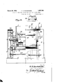
a The rotary motion is imparted to the composite mixing device from' an-electric motor .;31,shown in Figures 1 and 4 of the drawings; Thismotoris provided with a drive pulley; or sprocket 32, shown inFigure 1, a from" which a belt or sprocket chain 33leads to sprocket 34 on a shaft 35journalled at opposite ends in'thestandards 2 and Oneach chain 37 leads'to a large pulley 'or sprocket T A slightly difierent form of drive in Figureslb and 6, and includes an electric: motor 39 provided with a pinion 40 in-inesh with a gear4l ,carriedby a shaft 42 jour jacentshaft 18, whereby eachicross-head 17" wheel 38 carried by the outer end of the shaft 18, whereby arelatively slow but powerful rotary motion will'beimparted to the shaft 18.; It will of course be understood that similar pulleys 36 -and '38 and a drive belt or chain; 37 are provided within thehollow standard 3, whereby both cross-heads 17 .are simulta=- neously and independentlyrotated with a slow butpowerful motion, I
nalled at opposite endsin the inner walls of the standardsj2 and '3. The shaft 42carries,
withinieach hollow standard, apinion 43 in mesh with a large gear 44 carried by the adisindependently driven with aslow but powerful motion; It will here be noted that the i wormwheel 13, the worm 14and the shaft 15, in the arrangement shown in'Figures 5 and 6, i
are located at the outer side of they gear 44,
whereasin the arrangement shown in Figures ;1 to- 4 -1nclus1ve, these same members are located between the 11I11'1eB W'allf of the standard 2 and the drive belt 37.
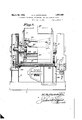
For the, purpose of" preventing leakage from the interior of the bowl 4- outwardly thru each-"bearing and also leakageof'the lubricant inwardly into the interior of the bowl, there is provided means, best shown in Figure 6, to, accomplish this result, which includeswashers 45 embracing theinnerend of the bearing sleeve 7 with one of the washers engaging the adjacent face of thecros's head 17. Inward pressure is exerted against. these washers by springs 46 mounted in bores, or openings 47extendinglongitudinal thru thesleeve 7. Each spring is held. in place by a screw; threaded plug48 fitted into the screw threaded outer end ofthe bore, where-f by the tension of each spring may be adjusted so as to apply the necessary pressure to the groupof washers 45 to prevent 'theescape or leakage of liquid from thebowl through the bearing; If desired, a pin 49 may be employed to" prevent rotation of the washerv 7 member; which bears against cross-head 17.,
,Lubrication may be supplied to the, hear;
ing bearing through a: longitudinal passage, 5Q formedjin the shaft. 18 andleading in) is shown wardly :fronr thev outer; end' thereof a toa cross passage 51 opening thruthe exterior.- of the shaft. Ar suitable oil port 52 is pro vided through" the inner end of the'sleeve 19 andleading to a recess 53'inthe exterior of the sleeve and. withinrthe' shaft opening in thei-cross-head l7. Anioil chamber 54. is provided in the inner-walls orthe sleeve 7.
A slightly modified form ,of bearing for the bowl 4 is illustrated in Figure, 4 of the drawings, wherein it will be seen that instead of having a'separate sleeve 7, as in F igure 6, thesleeve and. thehub 6 are integral.
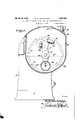
1 The shape or confi urationuof,thebowl in a plane atiright'angles'to the axis of rotation of thecompos'ite mixlngndevlce is an 1111 porta-nt feature of this'inventiomand is well shown in, FiguresEZand "3 of the drawings,
The bowl is U-shaped in vertical 'cross-section, nott'ruly cylindrical, aswill 'be'undere stood by reference-to Figure 2, wherein the dotted circle A indicates the path of the out-1 side of-the member 23 while the dotted circle B is also, scribed from the axis of rotation of the dough mixing: device and is intended for:
comparison with the shapeof the bowl. It
to the bowl at a point near the bottom ther of,"as at D, than to the topand the front and 1 back walls thereof, f'so-that there is a crescent shapedspace designated C. between theback wall of the bowl and-the paths of the mem- j bers 23, 26 and 29 fora purpose as will hereinafter-appear. The lower front wall of the: bowl is bowed outwardly, as at 55,'to provide;
an enlarged collecting space at the lower :front portion; of thebowl to accommodate:
the dough and enable. the collection there of in ainanner and for the will be hereinafter described. a t I I For thepurpose of introducing the water,
flour and other ingredients, the t portion of the bowl isi normally lyegistrersl will be noted that the shaft 18 or axisof 1-0 tation'ol the mixing device,is below the hori- 'zontal center of the bowl, so that the paths l of the elements'23, 26, and'29 come closer purpose which;
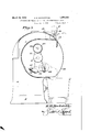
front of the bowl and is normallyclosed by a lid or-door 59 hinged as at ISO-upon the frontof ;the hopper 57. A'suitable handle bar 62 is provided upon the front-lower portion of the lid or ,door 59 for convenience in 5 I lifting th'esame; The counterweighted arm 61'w1ll supportthe,lidoredoor 59in its open, orelevated positiomas shown in-VFigure of the drawings,"when'the bowl has beentilted from itsoperative upright position as shown in Figure 2, to its dumping posit-ion;
as shown "in Figure 3.-i The lower edge v.of'
the lid or door 59 meets the upper edge of the opening 56 in the bowl in a beveled joint so as to insure a tight fit between these parts and to hold the door closed, as it is important 3 to prevent the escape of ingredients in the Y ported by the inner end portions of the two sleeves 19 at opposite ends of the bowl. It
will therefore be understood that the weight of the cross-heads 17 and their connecting parts does not come upon the stub shafts 18,
but upon the inner projecting ends ofthe sleeves 19 and consequently there is no tendency of the shafts to tilt longitudinally within the sleeves and become worn by the cutting action of the end edges of the sleeves.
This improved construction obviates the necessity of frequent replacements of the I as stub shafts 18.
In using the apparatus of the present in- Vention, it will of course be understood that water, flour, yeast and any other desired ingredients are introduced into the bowl thru the opening in the top thereof, and then the electric motor is started so as to rotate the mixing device. It is, of course, desirable to form the flour, water and other ingredients into a plastic mass as quickly as possible. and
at the same time to agitate the materials so as to bring about a uniform distribution of all'the ingredients. In this connection, it will be explained, by reference to Figure 2 of the drawings, wherein the dotted line E indicates the level of the liquid and F indicates the top of the dry ingredients, that the roller 23 presents a large surface to the dry ingredients and forces the latter into the liquid on the downward movement of the roller at the back of the bowl, which results in a very quick and uniform incorporation of the dry ingredients with the liquid.
Following the action of the roller 23 comes the action of the cross-bar 29 which presents its fiat face to the top surface of the dry ingredients, as indicated in dotted lines in F igure 2 of the drawings, due to the crank mountings of the ends of the bar. Inasmuch as the bar necessarily trails the pivotal axis of its crank terminals, such crank terminals are disposed at an obtuse angle to the main portionof the bar and operate to force the ingredients inwardly in opposite directions from the ends of the bowl towards the center.
thereof. v
Following the action of the bar 29 comes the action of the rigid cross-bar 26, which passes downwardly thru the dry ingredients and the water and causes an effective agitation thereof, in addition to which, and by reason of the lengthwise inclination of the opposite half sections of the bar, the ingredients are forced or crowded inwardly in opposite directions from the opposite ends of the bowl. It will here lie-explained that by reason of the comparatively large surface of the roller 23 which is presented to the dry ingredients, there is a forcing of such dry ingredients into the liquid as distinguished from prior practice wherein agitation devices presenting relatively narrow surfaces merely cut thru the lnaterials'and stir them as in stirring with a spoon. The agitator bar 26 has an action similar to that of the roller 23 because'of the comparatively large surface 28 thereof which is presented toand works upon the dry ingredients as the bar passes downwardly at the back of the bowl. In the initial mixing stage, the roller 23 does not rotate upon its axis or the reason that the roller passes downwardly thru' the dry ingredients and the liquid which present substantially equal pressures at opposite sides of the roller such that there is no tendency of the roller to rotate on its axis. This is important in that there would be a scattering'of the ingredients around the bowl if there was a positive rotation of the roller on its axis during the initial stages of the mixing of the ingredients.
The mixing operations of the roller 23 and the bars 26 and 29, which of course include the compressing of the dry ingredients into the liquid, are so effective that the ingredients are formed into a plasticmass in about 15 seconds. Hitherto, so far as I am aware, the mixing of dry ingredients and liquid into a plastic mass has usually required from one to two minutes.
The action'of theapparatus on the plastic mass formed as the result of the mixing oper ation will be readily understood by reference.
to Figures 8 to 22 inclusive, which'show the action on the dough mass at approximately one-fifth second intervals. \Vhile the crossbars 26 and 29 have a working or kneading effect upon the mass of dough, they also move the dough around the bowl, while the roller 23 rolls over the dough while the latter is sta tionary and compresses it against the walls of the bowl in the manner indicated in the drawings. The mixing makes a complete revolution or cycle during each second of operation of the apparatus, as
will be readily seen by an inspection of Fig- 11 res 8 to 22 inclusive, but it takes about three cycles to move the batch of dough entirely around the bowl so that the kneading roller 23 operates a plurality of times upon the dough while the latter is making one complete cycle of movement around the bowl. It
will noted that there is no ribboning and and kneading device tearing ofithe dough massfb ut on the "contrary there is a working or kneading or compression of :the idoughiagainst the walls of bowl where'the doughis pressed against the the bowl.
During a singlerycle :of the working and mixing device,suchfor'instance ashas been shown iii-Figures 8 to 12 inclusive, the agitator bars26 and 29 operate to carry the batch 'of doughfr'omi the upper front portion ofthe. I
bowl across the top thereof to the back of the back'of the bowl by the members 26 and 29, after whichthe roller 23 comes into working engagement with the mass of dough andcompresses it against the back wall of the'bowl and rolls over the surface ofthe dough as-in-- dicatedin Figures-10, 11 and 12. About as soon' as the'roller 23 clears the lower end'ot the batch of dough, see Figure. 12, the bars 126 and 29 again come into. engagement with. theidou gh -and effect a'punching and kneadiing action upon the'plastic mass as illustrated ini'Figuresl and L": Also the bars26- and l 1,29 effect a feecling acti'onajupon the plastic mass to move the: same inan orbit around the bowl. It willherebeexplained that the bars 26 and 29 effect an intermittent feeding or moving of the plasticmass inan-orbit around-the interior of the bowl, and that the mass' is station ary, or substantially so, in the intervals between, 'the' feeding movements thereof, The roller 23.?act s upon the plastic inventionqi's' the folding; over of the dough mass upon itself; as, illustrated in Figures 9 and 10, and {13"and 145. In the condition shown in Figure 9 .withfthe bars 26 and 29 adjacent the lower vend ofthe dough, the upper portion'of the dough unsupported and-therefore foldsdownwardly upon the lower portionof'the dough,as in Figure 10,- whereupon. the roller 23" comes along and presses together'the folded over portions of operation of. the apparatus, as shown in Figure 14.1 Immediately; succeeding the 'action'of the bars-26f and 29, as shownin Figures 13 and 14:, which actionadvances the- 0 dough along the bottom of the bowl from.
" the doughtherebyclosely siinulating hand manipulation of the dough in a simple and eff cient manner, and accomplishing hymefchanical' means "that which, has heretofore been accomplished by hand manipulation.
This lapping over or folding of thedough is also accomplished, .at another stage of the the back to the frontthereof, the rolling compressing actionofthe roller 23 -isexerted as in Figures 15,16 and 17. Then the bars 26 and 29 again come into play,v as in Figures 1,8 and '19, so as to move the dough'upwardly 1 apparatus.
along the from; an of'the bowl, and then the roller23 rollsover the dough and compresses it against the frontwall of thebowl; During that if there are any separate portions of dough, they will be gathered together in the collecting space and united with the main I a mass of dough, thereby tomaintain the dough ina mass and insure the treatment thereof as aunit by the bars 26and 29 andthe roller 23 in thevariousistages of operation of the It willv now be understood that the bars 26 and QQ'intermittently adyance the dough Y mass as a unit in an orbit around the "bowl andat theisame time knead and work the dqugh; while the'roller 23 wipes across the surface'of the'dough with 'a rollingjnaction,
the advancing off the dough'upwardlyf from the bottom of the :bowl across the front wall thereof, a very importantfeature results in in the intervals between the advancing action of the bars 26 and 27 and while the dough mass-is stationary, thereby effecting compression of the dough against the, walls of the:
bowl without producing any'surface stretch-' ing or tearing of the'dough.
tion er Figure 9,, the dough'is merely carried acrosslfl e upper "portion of the bowl from the front'tothe back bythe bars 26 and'29' withoutany intended or'appreciable worlri'ng of the dough against thetop of the bowl.-
Ihe dough is worked and compressed against F rom' the position of' Figure'S to'theposithe back; bottom and front wallsonly of the bowlyand is. merelycarried across the upper portion of the bowl without any intentional working thereof againstthe topof 'thebowl.
Tlie mixing developing andfconditioning device bf the present apparatus makes about three complete cycles while the dough mass as a 1unit is beingmoved only once aroundthe mass. by the cross-bars 26 and'29 and the roller produces an important deyelopm'ent'of the,
gluten which results ina strengthening of In'the second stage of the operation ofthe apparatus, the peculiar working of the dough the walls ofthe cell structure ofthedough,
whichincreased wall strength enables the cell wallsitoabsorb and carry materially :more
weight of the moisture than with "prior meth ods, thereby giving the baked breadthe qual ity of maintaining its freshness for a much longer time than ordinary. The present manner of workingthedough'has a strength eningeffect thereon -similartothatyproduced inforging metal: Ithas been found in pr c. tice thatby reason of thepresent method of hydration and development vof the gluten, there" is-.i'1o danger of over-development by running the apparatus longer than is necesp moisture without brealnngdown'underthe 'jsary forthe desiredhydration anddevelopment. As a ma'tteriof fact the-"prolong'ed 1 operation of the apparatus results mer'ely' in a further strengthening of the cell walls,
of the roller 23.
lVith a more uniform grain or cell structure.
ordinary methods and apparatus, excessive working of the dough will result in ribboning, stretching and tearing of the dough and the breaking down of the cell walls, thereby liberating moisture and producing a noticeable softening of the dough and an exterior which is wet and sticky to the touch. \Vith the present method, there is no ribboning of the dough; there is a high moisture content but without wetness or stickiness to the touch;
and a materially increased cell-wall strength producing resiliency, flufliness and life in the dough mass. Also,-as the dough is maintained in a'unitary and dry mass, it may be dumpedcleanly as a unit from the bowl without leaving any dough portions clinging to the bowl walls and to the mixing and developing device. A further very important fea- ,ture of the present invention resides in. the dough gathering action of the bars 26 and 29followed by the compression rolling action Ashereinbefore described the bar 29 necessarilvtrails its pivot termi- .nals,: consequently the obtusely disposed crank ends 30 will force or crowd the dough from the ends of thebowl inwardly towards the center thereof'and thus prevent the dough from collecting in the end portions of the bowl where the cross-heads 17 rot-ate; Hence the cross-head's 17 rotate in spaces entirely free from dough sothat there is no collecting of the dough upon the cross-heads. The oppositely inclined portions of the bar 26 also force the dough towards the center of the bowl and form it into a unitary mass having a substantially convex outer face or raised at its centenas illustrated inFigure 23, after which the roller 23 travels across the convex face or raised'center of the mass with a rolling compressing action that flattens out the mass which is thereafter again gathered together by the action of the cross-bars. Thus there is an intermittent feeding and gathering together of the dough into a heaped up convexed mass by the cross-bars, followed immediately by the rolling compressive action of the roller in each stationary interval of the dough mass between successive feeding or advancing movements thereof.
What is claimed is:
1. A dough working apparatus, comprising a bowl, means for bodily moving a dough mass in an orbit around the bowl in contact with the walls thereof, means for imparting a succession of rolling compressive actions upon the dough between the intermittent movements thereof, and means to prevent ribboning of the dough around the means for compressmglthe dough.
mass. inan orbit around the bowl in contact portions of thedough from collecting at the a. succession of rolling compressive actions upon the dough between the intermittent movements thereof, and means to prevent 7) axis of the path of bodily movement of the dough. Y
'3. A dough working apparatus, comprising abowl, a pair of spaced rotatable crossheads mounted within the bowl, a dough 'i i working roller rotatably mounted between the cross-heads at one side of the axis thereof and spaced cross-bars extending between the other ends of the cross-heads and disposed to work upon and feed a mass of dough it around the bowl in contact with the walls thereof, one ofsaid cross-bars having crank terminals rotatably mounted upon the crossheads. I
4. A dough working ap aratus,comprising 95 a bowl, spaced cross-heads rotatably mounted in the bowl, a dough working roller rotatablymounted between the cross-heads at one side of axis of rotation thereof, and a pair of cross-bars extending between the otherends of the cross-heads, the opposite half-sections of one the cross-bars being inclined in opposite directions. and the other cross-bar having crank terminals pivotally mounted upon the cross-heads.
In a dough working apparatus, the combination of'a bowl, a pair of rotatable crossheads mounted therein on a horizontal axis,
a dough working roller rotatably mounted between corresponding ends of the cross- 1 heads, and cross-bars connecting the other ends of the cross-heads, one of said cross-bars having crank terminals pivotally mounted upon the cross-heads, the lower front wall of the bowl having an outwardly bulged portion defining a dough collecting space.
6. A dough working apparatus, comprising a bowl, means for intermittently moving a dough mass in an orbit around the bowl in contact with the walls thereof, and other means for imparting a succession of rolling compressive actions upon the dough mass between the intermittent movements thereof, the loweriupright portion of one of the'walls of the bowl being provided with an outward- ].y' bulgedportion forming a dough collecting space; i
HERBERT H. HACKSTEDDE.
L. HAMMOND 1,851,389
TABLE March 29, 1932.
Filed Aug. 15. 1929 5 Sheets-Sheet al fto'znm o
Publications (1)
| Publication Number | Publication Date |
|---|---|
| US1851388A true US1851388A (en) | 1932-03-29 |
Family
ID=3423612
Family Applications (1)
| Application Number | Title | Priority Date | Filing Date |
|---|---|---|---|
| US1851388D Expired - Lifetime US1851388A (en) | H h hackstedde |
Country Status (1)
| Country | Link |
|---|---|
| US (1) | US1851388A (en) |
Cited By (2)
| Publication number | Priority date | Publication date | Assignee | Title |
|---|---|---|---|---|
| US3406643A (en) * | 1964-11-23 | 1968-10-22 | Baker Perkins Inc | Method and apparatus for mixing dough |
| US20080080300A1 (en) * | 2004-09-28 | 2008-04-03 | Basf Aktiengesellschaft | Mixing Kneader and Process for Preparing Poly(Meth)Acrylates Using the Mixing Kneader |
-
0
- US US1851388D patent/US1851388A/en not_active Expired - Lifetime
Cited By (3)
| Publication number | Priority date | Publication date | Assignee | Title |
|---|---|---|---|---|
| US3406643A (en) * | 1964-11-23 | 1968-10-22 | Baker Perkins Inc | Method and apparatus for mixing dough |
| US20080080300A1 (en) * | 2004-09-28 | 2008-04-03 | Basf Aktiengesellschaft | Mixing Kneader and Process for Preparing Poly(Meth)Acrylates Using the Mixing Kneader |
| US8070351B2 (en) * | 2004-09-28 | 2011-12-06 | Basf Aktiengesellschaft | Mixing kneader and process for preparing poly(meth)acrylates using the mixing kneader |
Similar Documents
| Publication | Publication Date | Title |
|---|---|---|
| US1851388A (en) | H h hackstedde | |
| CN113182262A (en) | Intelligent production line for bletilla striata decoction pieces | |
| JP2950498B2 (en) | Bread dough manufacturing process | |
| US2555908A (en) | Starch gluten separation | |
| US2740362A (en) | Method and apparatus for dividing and panning bread dough | |
| CN105053116B (en) | Full-automatic pizza production line | |
| US3651768A (en) | Method for separating wet gluten or glutenin from flour | |
| CN207491950U (en) | A kind of process equipment of cassia seed noodles | |
| US1958808A (en) | Dough and flour salvager | |
| US2112927A (en) | Dough kneader | |
| CN218278494U (en) | Automatic dough kneading device for continuous solid-liquid automatic batching | |
| US1751548A (en) | Machine for the mixing, aerating, and like treatment of various materials | |
| CN105851456B (en) | Automatic processing equipment and processing method for fried gluten balls | |
| US1374765A (en) | Mixer for dough and like plastic substances | |
| US2600117A (en) | Mixing or kneading machine | |
| US1845329A (en) | Dough kneader | |
| CH660670A5 (en) | DEVICE FOR DRYING THE SMALL VEGETABLES AND SALADS. | |
| US2575007A (en) | Machine for painting the interior of pipe bowls | |
| CN111743079A (en) | Glutinous rice cake beating device for food processing | |
| US19103A (en) | Btjtter-wokkek | |
| US3247808A (en) | Method of making an annulus | |
| CN112471499A (en) | Paste stirring and cutting strip forming equipment | |
| CN221602156U (en) | Feeding structure and wheat gluten drying device | |
| CN212545309U (en) | Noodle press for noodle processing | |
| US3031979A (en) | Apparatus for making an annulus |