EP1795987A2 - Stellantrieb - Google Patents
Stellantrieb Download PDFInfo
- Publication number
- EP1795987A2 EP1795987A2 EP06015917A EP06015917A EP1795987A2 EP 1795987 A2 EP1795987 A2 EP 1795987A2 EP 06015917 A EP06015917 A EP 06015917A EP 06015917 A EP06015917 A EP 06015917A EP 1795987 A2 EP1795987 A2 EP 1795987A2
- Authority
- EP
- European Patent Office
- Prior art keywords
- cylinder
- valve
- actuator
- piston
- screw shaft
- Prior art date
- Legal status (The legal status is an assumption and is not a legal conclusion. Google has not performed a legal analysis and makes no representation as to the accuracy of the status listed.)
- Granted
Links
Images


Classifications
-
- B—PERFORMING OPERATIONS; TRANSPORTING
- B64—AIRCRAFT; AVIATION; COSMONAUTICS
- B64C—AEROPLANES; HELICOPTERS
- B64C13/00—Control systems or transmitting systems for actuating flying-control surfaces, lift-increasing flaps, air brakes, or spoilers
- B64C13/24—Transmitting means
- B64C13/38—Transmitting means with power amplification
- B64C13/40—Transmitting means with power amplification using fluid pressure
- B64C13/42—Transmitting means with power amplification using fluid pressure having duplication or stand-by provisions
-
- B—PERFORMING OPERATIONS; TRANSPORTING
- B64—AIRCRAFT; AVIATION; COSMONAUTICS
- B64C—AEROPLANES; HELICOPTERS
- B64C13/00—Control systems or transmitting systems for actuating flying-control surfaces, lift-increasing flaps, air brakes, or spoilers
- B64C13/24—Transmitting means
- B64C13/26—Transmitting means without power amplification or where power amplification is irrelevant
- B64C13/28—Transmitting means without power amplification or where power amplification is irrelevant mechanical
- B64C13/341—Transmitting means without power amplification or where power amplification is irrelevant mechanical having duplication or stand-by provisions
-
- B—PERFORMING OPERATIONS; TRANSPORTING
- B64—AIRCRAFT; AVIATION; COSMONAUTICS
- B64C—AEROPLANES; HELICOPTERS
- B64C13/00—Control systems or transmitting systems for actuating flying-control surfaces, lift-increasing flaps, air brakes, or spoilers
- B64C13/24—Transmitting means
- B64C13/38—Transmitting means with power amplification
- B64C13/50—Transmitting means with power amplification using electrical energy
- B64C13/505—Transmitting means with power amplification using electrical energy having duplication or stand-by provisions
-
- F—MECHANICAL ENGINEERING; LIGHTING; HEATING; WEAPONS; BLASTING
- F15—FLUID-PRESSURE ACTUATORS; HYDRAULICS OR PNEUMATICS IN GENERAL
- F15B—SYSTEMS ACTING BY MEANS OF FLUIDS IN GENERAL; FLUID-PRESSURE ACTUATORS, e.g. SERVOMOTORS; DETAILS OF FLUID-PRESSURE SYSTEMS, NOT OTHERWISE PROVIDED FOR
- F15B15/00—Fluid-actuated devices for displacing a member from one position to another; Gearing associated therewith
- F15B15/08—Characterised by the construction of the motor unit
- F15B15/088—Characterised by the construction of the motor unit the motor using combined actuation, e.g. electric and fluid actuation
-
- F—MECHANICAL ENGINEERING; LIGHTING; HEATING; WEAPONS; BLASTING
- F15—FLUID-PRESSURE ACTUATORS; HYDRAULICS OR PNEUMATICS IN GENERAL
- F15B—SYSTEMS ACTING BY MEANS OF FLUIDS IN GENERAL; FLUID-PRESSURE ACTUATORS, e.g. SERVOMOTORS; DETAILS OF FLUID-PRESSURE SYSTEMS, NOT OTHERWISE PROVIDED FOR
- F15B20/00—Safety arrangements for fluid actuator systems; Applications of safety devices in fluid actuator systems; Emergency measures for fluid actuator systems
-
- F—MECHANICAL ENGINEERING; LIGHTING; HEATING; WEAPONS; BLASTING
- F15—FLUID-PRESSURE ACTUATORS; HYDRAULICS OR PNEUMATICS IN GENERAL
- F15B—SYSTEMS ACTING BY MEANS OF FLUIDS IN GENERAL; FLUID-PRESSURE ACTUATORS, e.g. SERVOMOTORS; DETAILS OF FLUID-PRESSURE SYSTEMS, NOT OTHERWISE PROVIDED FOR
- F15B15/00—Fluid-actuated devices for displacing a member from one position to another; Gearing associated therewith
- F15B15/08—Characterised by the construction of the motor unit
- F15B15/14—Characterised by the construction of the motor unit of the straight-cylinder type
- F15B2015/1495—Characterised by the construction of the motor unit of the straight-cylinder type with screw mechanism attached to the piston
Definitions
- the present invention relates to an actuator that can drive a movable rod using fluid pressure or electric power.
- Japanese Patent Publication No. JP-A-11-272332 discloses a positioning cylinder device.
- the cylinder device has a ball screw and a nut that are disposed in a piston rod of a cylinder.
- a linear motion of the piston is converted into a rotation motion through the ball screw, and the rotation motion is converted into a positional signal by an angle sensor (for example, an encoder).
- an angle sensor for example, an encoder
- a switch valve is fed back on the basis of the signal, and the piston is positioned.
- JP-A-11-272332 With this configuration, a position of a stroke end of the piston rod can be changed. Further, in JP-A-11-272332 , there is disclosed a case where the piston rod is driven by a motor as well as an electro-hydraulic servo valve.
- the invention has been made in consideration of the above-described problems, and it is an object of the invention to provide a redundant actuator that can operate a movable rod using either electric power or fluid pressure.
- an actuator having the following configuration. That is, the actuator includes a cylinder, a piston that is disposed in the cylinder and moves by supply and exhaust of a working fluid to and from the cylinder, a movable rod that is connected to the piston, a screw shaft, at least a part of which is inserted into the movable rod, a nut that is screwed to the screw shaft and moves integrally with the piston, and an electric motor that rotates the screw shaft forward or backward.
- the output rotation of the electric motor may be transmitted to the screw shaft through a gear mechanism so as to drive the screw shaft.
- the output rotation of the electric motor can be reliably transmitted to the screw shaft through the gear mechanism. Further, a degree of freedom for layout of the electric motor can be increased, and a compact actuator can be provided as a whole.
- the actuator according to the aspect of the invention may further include a switch valve that switches the supply and exhaust of the working fluid to and from the cylinder.
- the movable rod can be reliably driven using fluid pressure by a simple operation of switching of the switch valve.
- the actuator according to the aspect of the invention may have the following configuration.
- the cylinder may be a reciprocating cylinder.
- the actuator may further include a mode selector valve that switches between at least two positions of a first position where one port of the cylinder and the other port do not communicate with each other and a second position where both ports communicate with each other.
- the actuator according to the aspect of the invention may have the following configuration.
- the actuator may further include a bias spring that biases the second switch value in a direction to be switched to the second position.
- the second switch value may be kept at the first position against the bias spring by working fluid pressure.
- the mode selector valve may cause one port of the cylinder and the other port to communicate with each other through an orifice valve.
- the movable rod may be connected to a control surface of an aircraft.
- the above-described actuator is particularly suitable for an aircraft that requires a redundant driving mechanism.
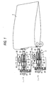
- Fig. 1 is a schematic perspective view showing the configuration for driving a control surface by an actuator according to an embodiment of the invention.
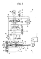
- Fig. 2 is a cross-sectional view showing the configuration of an individual actuator and a circuit diagram of an oil pressure circuit.
- Actuators 1 shown in Fig. 1 are to drive a control surface 2 provided in an aircraft. Two actuators 1 are provided in a pair.
- Fig. 2 shows the configuration of an individual actuator 1.
- the actuator 1 primarily includes a cylinder mechanism 11, an oil pressure circuit 12 that drives the cylinder mechanism 11, and an electric motor 13 that drives the cylinder mechanism 11.
- the cylinder mechanism 11 includes a cylinder 21, and a piston 22 that is disposed in the cylinder 21.
- the piston 22 is fitted into the cylinder 21 oil-tight, and reciprocates in an axial direction of the cylinder 21.
- the piston 22 is provided to divide the internal space of the cylinder 21 into two spaces. The divided two spaces communicate with ports 31 and 32 to be described below, respectively.
- One end of a movable rod 23 is integrally connected to the piston 22.
- the other end of the movable rod 23 protrudes from the cylinder 21, and is connected to the control surface 2 of the aircraft.
- the two ports 31 and 32 that can perform supply and exhaust of working oil (working fluid) are formed in the cylinder 21.
- the cylinder mechanism 11 is a so-called reciprocating hydraulic cylinder.
- an oil pressure circuit 12 that performs supply and return pressure oil to and from the two ports 31 and 32 so as to drive the piston 22 will be described.
- the oil pressure circuit 12 primarily includes a pressure line 41 that supplies pressure oil, a compensator line 42 that returns pressure oil, a switch valve 51, a mode selector valve 52, and a solenoid valve 53.
- the switch valve 51 is a three-position switch type, and includes four ports P, T, A, and B.
- the solenoid valve 53 is a two-position switch type, and includes three ports P, T, and A.
- the pressure line 41 has two branches. One of the two branches is connected to the port P of the switch valve 51, and the other is connected to the port P of the solenoid valve 53.
- the port T of the switch valve 51 and the port T of the solenoid valve 53 are connected to the tank line 42.
- the switch valve 51 can be switched among three positions of a position where all the ports P, T, A, and B are blocked, a position where the ports P and A, and the ports T and B communicate with each other, and a position where the ports P and B, and the ports T and A communicate with each other by a solenoid. With this configuration, the supply of working oil to the individual ports 31 and 32 of the cylinder 21 is switched, and thus the piston 22 and the movable rod 23 can be hydraulically driven in a desired direction.
- the mode selector valve 52 is disposed between the switch valve 51 and the cylinder 21 and is configured to switch between a hydraulically driving mode and an electrically driving mode. Specifically, the mode selector valve 52 can be switched between a first position where the ports A and B of the switch valve 51 respectively communicate with the ports 31 and 32 of the cylinder 21, and a second position where the ports A and B are blocked and the ports 31 and 32 of the cylinder 21 communicate with each other. At the second position, the ports 31 and 32 communicate with each other through an orifice valve 40 that limits a flux of working oil.
- a bias spring 35 is attached to the mode selector valve 52 and biases a valve body, such that the mode selector valve 52 is switched to the second position.
- the solenoid valve 53 is an electromagnetic valve. The solenoid valve 53 can be switched between the position of the PA connection and the position of the TA connection in connection with the operation of an operator (not shown). Then, working oil of the port A of the solenoid valve 53 is guided, and thus the valve body of the mode selector valve 52 can be repelled against the bias spring 35.
- a filter 36 that filters working oil or a check valve 37 that prevents flowing backward is provided in the pressure line 41. Further, a pressure holding mechanism 38 that appropriately holds a pressure of the tank line 42 is provided in the tank line 42.
- a differential pressure sensor 39 that detects a differential pressure between the two ports 31 and 32 of the cylinder 21, a relief valve 46 that regulates an oil pressure of the entire circuit to be connected to both ports 31 and 32 through the check valve 45, or a check valve 47 that supplies working oil of the tank line 52 when the pressure of the ports 31 and 32 of the cylinder 21 is decreased is provided in the oil pressure circuit 12.
- the electric motor 13 is attached to the side of the cylinder 21.
- An output shaft 24 of the electric motor 13 protrudes to the inside of a housing 25 that is formed integrally with the cylinder 21.
- An output gear 26 is fixed to a front end of the output shaft 24.
- a transmission shaft 27 is rotatably supported on the housing 25.
- the transmission shaft 27 is provided to be concentric to an axial line of the cylinder 21.
- a large-diameter gear 28 is fixed to one end of the transmission shaft 27.
- the large-diameter gear 28 is meshed with the output gear 26.
- the output gear 26 and the large-diameter gear 28 are spur gears.
- the other end of the transmission shaft 27 extends to an internal space of the cylinder 21, and a screw is provided on a circumferential surface of the extending portion so as to form a screw shaft 29.
- An insertion hole 33 is formed in the piston 22 and the movable rod 23, and the movable rod 23 is formed in a hollow cylindrical shape. A part of the screw shaft 29 is inserted into the insertion hole 33. Further, a nut 30 is fixed to a portion of the piston 22. The nut 30 is screwed to the screw shaft 29.
- the solenoid valve 53 is switched to the position of the PA connection.
- the mode selector valve 52 is hydraulically pressed in a direction against the bias spring 35 and then is switched to the first position.
- the position corresponds to the hydraulically driving mode.
- the port 31 of the cylinder 21 is connected to the port A of the switch valve 51, and the port 32 of the cylinder 21 is connected to the port B of the switch valve 51 (both ports 31 and 32 of the cylinder 21 do not communicate with each other).
- the switch valve 51 is switched, the working oil of the pressure line 41 is supplied to any one of the ports 31 and 32 so as to hydraulically drive the piston 22. Therefore, the control surface 2 that is connected to the piston 22 through the movable rod 23 can obliquely move in a desired direction.
- the mode selector valve 52 since the mode selector valve 52 is located at the second position, the port 31 and the port 32 communicate with each other, such that the movement of the piston 22 is not locked by the oil pressure in the cylinder 21. As such, the piston 22 and the movable rod 23 are screw-driven, and the control surface 2 can rotate in a desired direction.
- the orifice valve 40 is formed in the mode selector valve 52.
- the mode selector valve 52 When the mode selector valve 52 is switched to the second position (the electrically driving mode), the ports 31 and 32 of the cylinder 21 are connected to each other through the orifice valve 40. Accordingly, predetermined resistance can be given to the movements of the piston 22 and the movable rod 23 (damping effect), and a phenomenon that the control surface 2 resonates and minutely vibrates (so-called fluttering) during high-speed flying of an aircraft can be suppressed.
- the solenoid valve 53 an electromagnetic valve, may be switched to the TA connection position, and then the mode selector valve 52 may be switched to the second position, thereby setting the electrically driving mode (for example, forcibly).
- the actuator 1 of this embodiment includes the cylinder 21, the piston 22 that is disposed in the cylinder 21 and moves by the supply and exhaust of working oil to the ports 31 and 32, the movable rod 23 that is connected to the piston 22, the screw shaft 29, at least a part of which is inserted into the movable rod 23, the nut 30 that is screwed to the screw shaft 29 and moves integrally with the piston 22, and the electric motor 13 that rotates the screw shaft 29 forward or backward. Accordingly, the movable rod 23 can be driven using either electric power or oil pressure, and an actuator having redundancy can be provided.
- the output rotation of the electric motor 13 is transmitted to the screw shaft 29 through the gear mechanism having the output gear 26 and the large-diameter gear 28 so as to drive the screw shaft 29.
- the output rotation of the electric motor 13 can be reliably transmitted to the screw shaft 29 through the gear mechanism.
- the gear mechanism may have a deceleration function or an acceleration function.
- the actuator 1 of this embodiment further includes the switch valve 51 that switches the supply and exhaust of working oil to and from the cylinder 21. Accordingly, the movable rod 23 can be reliably hydraulically driven by a simple operation of switching of the switch valve 51.
- the cylinder 21 is the reciprocating cylinder
- the actuator 1 further includes the mode selector valve 52 that switches between the two positions of the first position where one port 31 of the cylinder 21 and the other port 32 do not communicate with each other and the second position where both ports 31 and 32 communicate with each other. Accordingly, when the movable rod 23 is driven by the electric motor 13, the mode selector valve 52 is switched to the second position, such that both ports 31 and 32 communicate with each other. Therefore, locking of the piston 22 by oil pressure can be prevented, and thus the movable rod 23 can be smoothly driven using electric power.
- the actuator of this embodiment further includes the bias spring 35 that biases the second switch value 52 in a direction to be switched to the second position. Further, the second switch value 52 is kept at the first position against the bias spring 35 by the working oil pressure. Accordingly, when the working oil pressure is lost, the second switch value 52 is automatically switched to the second position by the bias spring 35, such that both ports 31 and 32 communicate with each other. Therefore, locking of the piston 22 by oil pressure can be prevented, and thus the piston 22 can keep a state suitable for driving of the movable rod 23 by electric power.
- the mode selector valve 52 causes one port 31 of the cylinder 21 and the other port 32 to communicate with each other through the orifice valve 40. Accordingly, an oil pressure damping effect can be exhibited, and excessive vibration of the member to be driven (the control surface 2) can be attenuated.
- the movable rod 23 is connected to the control surface 2 of the aircraft. Therefore, the actuator 1 can be suitable for an aircraft that requires a redundant driving mechanism.
- a battery may be connected to the electric motor 13, and an energy generated by the rotation of the output shaft 24 according to driving of the piston 22 in the hydraulically driving mode. Then, in the electrically driving mode, the screw shaft 29 may be driven using the recovered energy.
- the screw shaft 29 and the nut 30 forming a linear driving mechanism have the ball screw.
- a trapezoidal screw may be used.
- other working fluid pressure such as air pressure, may be used.
- the mode selector valve 52 may be an electromagnetic valve that is switched by an electrical signal, not a valve that is switched by the oil pressure from the solenoid valve 53.
- the oil pressure of the pressure line 41 may be monitored by an appropriate sensor. Then, if abnormality, such as a reduction in oil pressure, is detected, the mode selector valve 52 may be controlled to be automatically switched to the second position.
- the solenoid valve 53 may not be provided, and working oil of the pressure line 41 may be directly guided to the mode selector valve 52.
- the orifice valve 40 of the mode selector valve 52 may not be provided according to the uses.
- the orifice valve 40 of the mode selector valve 52 in one of the two actuators 1, the orifice valve 40 of the mode selector valve 52 is not provided. In this configuration, fluttering of the control surface 2 can also be prevented by the orifice valve 40 of the other actuator 1.
- the mode selector valve 52 may be switched among a first position where the two ports 31 and 32 of the cylinder 21 do not communicate with each other, a second position where both ports 31 and 32 communicate with each other with no orifice valve, and a third position where both ports 31 and 32 communication with each other through the orifice valve 40.
- the mode selector valve 52 is switched to the second position during low-speed flying. Meanwhile, during high-speed flying when fluttering of the control surface 2 may occur, the mode selector valve 52 is controlled to be switched to the third position.
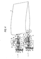
- one actuator 1 (on the upper side) may be driven by only the electric motor 13, and the ports 31 and 32 of the cylinder 21 of one actuator 1 may be connected to each other through an orifice valve 61 interposed between the ports 31 and 32.
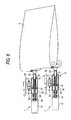
- the orifice valve 61 is an electromagnetic valve, and the orifice valve 40 is formed in the valve 62. Then, when the other actuator 1 (on the lower side) is in the hydraulically driving mode, the orifice valve 61 is opened to cause the ports 31 and 32 of the cylinder 21 to communicate with each other.
- the orifice valve 61 is closed to limit the flux between the ports 31 and 32 of the cylinder 21 by the orifice valve 40 in a valve body 62. Therefore, fluttering of the control surface 2 can be effectively suppressed.
- the electric motor 13 and the transmission shaft 27 may be connected to a planetary gear mechanism 55.
- a sun gear 56 is fixed to the output shaft 24 of the electric motor 13
- a small-diameter gear 60 is fixed to a carrier 58 that supports a planetary gear 57 meshed with the sun gear 56.
- the small-diameter gear 60 is meshed with the large-diameter gear 28 of the transmission shaft 27.
- the output rotation of the output shaft 24 of the electric motor 13 is decelerated by the planetary gear mechanism 55 and the gear mechanism having the small-diameter gear 26 and the large-diameter gear 28 through two steps with an increased torque, and then is transmitted to the transmission shaft 27.
- a clutch 59 that cuts off and transmits power may be interposed between the output shaft 24 of the electric motor 13 and the screw shaft 29.
- the clutch 59 for example, an electromagnetic clutch can be used.
- the clutch 59 is controlled to cut off power in the hydraulically driving mode, and the transmission shaft 27 or the output shaft 24 of the electric motor 13 is separated such that only the screw shaft 29 rotates when the piston 22 is hydraulically driven. Therefore, a power loss by inertia can be prevented.
- the clutch 59 is controlled to transmit power, simultaneously with the arrival of the electrically driving mode.
- the output shaft 24 of the electric motor 13 and the screw shaft 29 may be concentrically disposed and directly connected to each other.
- the gear mechanism may be not provided, and thus the configuration can be simplified.
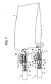
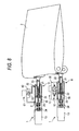
- the configuration, in which the electric motor 13 and the screw shaft 29 are directly connected to each other may be combined with the modification of Fig. 3, in which the mode selector valve 52 is the three-position switch type, as shown in Fig. 7, or may be combined with the modification of Fig. 4, in which the orifice valve 61 is provided, as shown in Fig. 8.
- the mode selector valve may be switched among at least three positions of a first position where the two ports of the reciprocating cylinder do not communicate with each other, a second position where both ports communicate with each other, and a third position where both ports communicate with each other through an orifice valve (an actuator shown on the upper side in Fig. 3 or 7) .
- the second switch value upon driving by electric power, the second switch value is located at the second position, such that the movable rod 23 can be smoothly driven by electric power. Further, when excessive vibration of the member to be driven (fluttering of the control surface 2) is concerned, the second switch value is located at the third position, such that the vibration can be suppressed by an oil pressure damping effect.
- Actuator includes a cylinder, a piston that is disposed in the cylinder and divides an internal space of the cylinder, a movable rod that is connected to the piston, a screw shaft, at least a part of which is inserted into the movable rod, a nut that is screwed to the screw shaft and moves integrally with the piston, and an electric motor that rotates the screw shaft forward or backward.
- the divided internal spaces are connected to each other through a valve (the orifice valve 61).
- the valve is switched between at least two positions of a first position (a valve opening position) where both internal spaces communicate with each other with no orifice valve and a second position (a valve closing position) where both internal spaces communicate with each other through an orifice valve (the actuator shown on the upper side in Fig. 4 or 8).
- the valve when the valve is located at the first position, the movable rod can be smoothly driven by electric power. Further, when excessive vibration of the member to be driven (fluttering of the control surface 2) is concerned, the valve is located at the second position, such that the vibration can be favorably suppressed by an oil pressure damping effect.
- an actuator mechanism that drives a member to be driven using a plurality of actuators.
- Each of the plurality of actuators has a cylinder, a piston that is movably disposed in the cylinder and divides an internal space of the cylinder, a movable rod that is connected to the piston, a screw shaft, at least a part of which is inserted into the movable rod, a nut that is screwed to the screw shaft and moves integrally with the piston, and an electric motor that rotates the screw shaft forward or backward.
- the plurality of actuators at least includes an actuator that connects the divided internal spaces to each other through an orifice valve, and an actuator that does not have orifice valve in a connection path of the internal spaces (see Figs. 1, 3, 4, 7, and 8).
- the orifice valve may be provided in only some of the plurality of actuators. With this configuration, excessive vibration of the member to be driven can be suppressed. Further, the configuration can be simplified.
Landscapes
- Engineering & Computer Science (AREA)
- Aviation & Aerospace Engineering (AREA)
- Fluid Mechanics (AREA)
- Mechanical Engineering (AREA)
- Automation & Control Theory (AREA)
- Physics & Mathematics (AREA)
- General Engineering & Computer Science (AREA)
- Chemical & Material Sciences (AREA)
- Analytical Chemistry (AREA)
- Actuator (AREA)
- Fluid-Pressure Circuits (AREA)
- Servomotors (AREA)
- Connection Of Motors, Electrical Generators, Mechanical Devices, And The Like (AREA)
- Transmission Devices (AREA)
Applications Claiming Priority (1)
| Application Number | Priority Date | Filing Date | Title |
|---|---|---|---|
| JP2005354215A JP4890845B2 (ja) | 2005-12-08 | 2005-12-08 | アクチュエータ機構 |
Publications (3)
| Publication Number | Publication Date |
|---|---|
| EP1795987A2 true EP1795987A2 (de) | 2007-06-13 |
| EP1795987A3 EP1795987A3 (de) | 2012-05-02 |
| EP1795987B1 EP1795987B1 (de) | 2013-07-17 |
Family
ID=37056518
Family Applications (1)
| Application Number | Title | Priority Date | Filing Date |
|---|---|---|---|
| EP06015917.5A Not-in-force EP1795987B1 (de) | 2005-12-08 | 2006-07-31 | Stellantrieb |
Country Status (4)
| Country | Link |
|---|---|
| US (1) | US7397209B2 (de) |
| EP (1) | EP1795987B1 (de) |
| JP (1) | JP4890845B2 (de) |
| ES (1) | ES2423198T3 (de) |
Cited By (9)
| Publication number | Priority date | Publication date | Assignee | Title |
|---|---|---|---|---|
| CN105366035A (zh) * | 2014-06-09 | 2016-03-02 | 波音公司 | 用于阻止飞行操纵面的装置和方法 |
| US9352825B2 (en) | 2013-07-26 | 2016-05-31 | Liebherr-Aerospace Lindenberg Gmbh | Aircraft |
| EP2192041A3 (de) * | 2008-12-01 | 2017-06-07 | Nabtesco Corporation | Elektrischer Aktuator für Flugzeugfahrwerk |
| WO2018114544A1 (fr) * | 2016-12-23 | 2018-06-28 | Safran Electronics & Defense | Surface mobile de vol ayant au moins un actionneur intégré |
| WO2018166658A1 (de) * | 2017-03-13 | 2018-09-20 | Sew-Eurodrive Gmbh & Co. Kg | Spindelantrieb, aufweisend einen elektromotor und einen von dem elektromotor angetriebenen spindeltrieb, und verfahren zum betreiben eines spindelantriebs |
| DE102018132122A1 (de) * | 2018-12-13 | 2020-06-18 | Liebherr-Aerospace Lindenberg Gmbh | Hydrauliksystem zur Bewegung eines Flugzeugruders |
| DE102019107976B3 (de) | 2019-03-28 | 2020-07-09 | Alfred-Wegener-Institut, Helmholtz-Zentrum für Polar- und Meeresforschung | Manövrierfähiger Messkörper zur Ermittlung von Messdaten mit Fehlfunktionsmodul |
| EP3879697A1 (de) * | 2020-03-09 | 2021-09-15 | Nabtesco Corporation | Redundanzsteuerungsvorrichtung für flugzeuge |
| US11459092B2 (en) * | 2018-05-08 | 2022-10-04 | Subaru Corporation | Aircraft steering system, aircraft, and aircraft steering method |
Families Citing this family (35)
| Publication number | Priority date | Publication date | Assignee | Title |
|---|---|---|---|---|
| US8827205B2 (en) * | 2009-05-08 | 2014-09-09 | Spectrum Aeronautical, Llc | Pneumatic blow-down actuator |
| DE102010021576A1 (de) * | 2010-05-26 | 2011-12-01 | Airbus Operations Gmbh | Vorrichtung für eine Stellklappe eines Tragflügels |
| FR2962774B1 (fr) * | 2010-07-19 | 2012-08-03 | Eurocopter France | Servocommande munie d'un dispositif de detection d'effort limite |
| JP5795215B2 (ja) * | 2011-08-17 | 2015-10-14 | ナブテスコ株式会社 | 電動アクチュエータ及び電動アクチュエータシステム |
| US20140033909A1 (en) * | 2012-08-03 | 2014-02-06 | Robert M. Murphy | Methods and apparatus to control movement of a component |
| JP6178571B2 (ja) * | 2012-12-26 | 2017-08-09 | 三菱航空機株式会社 | 動翼のアクチュエータ装置、航空機の動翼、及び、航空機 |
| JP6230873B2 (ja) * | 2013-10-24 | 2017-11-15 | ナブテスコ株式会社 | 電動アクチュエータ及びアクチュエータユニット |
| US9553467B2 (en) * | 2013-11-05 | 2017-01-24 | Nabtesco Corporation | Distribution apparatus |
| JP6080792B2 (ja) * | 2014-03-24 | 2017-02-15 | 日立建機株式会社 | アクチュエータの駆動装置 |
| JP2015218466A (ja) * | 2014-05-15 | 2015-12-07 | 三井金属アクト株式会社 | ドア開閉装置およびドア開閉方法 |
| DE102014224257A1 (de) * | 2014-11-27 | 2016-06-02 | Robert Bosch Gmbh | Linearaktuator |
| JP6727484B2 (ja) * | 2016-02-25 | 2020-07-22 | 多摩川精機株式会社 | 冗長系伸縮型二重経路を有する航空機用リニアアクチュエータ |
| US10458557B2 (en) | 2016-04-20 | 2019-10-29 | Sikorsky Aircraft Corporation | Hydraulic actuator force fight mitigation mechanism |
| EP4023853B1 (de) * | 2017-01-13 | 2023-07-05 | Vanderbilt University | Linearaktuator zur asymmetrischen stromerzeugung und -ableitung |
| US10737764B2 (en) | 2018-04-13 | 2020-08-11 | The Boeing Company | Base flight control member orientation mechanism and control |
| US10947997B2 (en) | 2018-04-13 | 2021-03-16 | The Boeing Company | Aircraft hydraulic system with a dual spool valve and methods of use |
| US10793261B2 (en) * | 2018-04-13 | 2020-10-06 | The Boeing Company | Electro-mechanically biased supercritical flight control surface loading to reduce high pressure actuation cycles |
| US10723441B2 (en) | 2018-04-13 | 2020-07-28 | The Boeing Company | High-speed-deployed, drum-brake, inertia disk for rack and pinion rotational inerter |
| US10711809B2 (en) | 2018-04-13 | 2020-07-14 | The Boeing Company | Aircraft hydraulic system with a dual spool valve and methods of use |
| US11072418B2 (en) | 2018-04-13 | 2021-07-27 | The Boeing Company | Hydraulic system for an aircraft |
| US10526071B2 (en) * | 2018-04-13 | 2020-01-07 | The Boeing Company | Hydraulic systems and methods to control a member |
| US10935053B2 (en) | 2018-10-26 | 2021-03-02 | Ellrich Engineering, Llc | Space-constrained hybrid linear actuator |
| JP6874755B2 (ja) * | 2018-12-21 | 2021-05-19 | コベルコ建機株式会社 | ジブ係留装置 |
| KR102123066B1 (ko) * | 2019-12-27 | 2020-06-26 | (주)가온텍 | 장방형 침전지의 수압 구동방식이 적용되는 왕복형 슬러지 수집기 |
| KR102123049B1 (ko) * | 2019-12-27 | 2020-06-26 | (주)가온텍 | 실린더형 수압 구동방식이 적용되는 침전지의 슬러지 수집기 |
| US11187023B2 (en) * | 2019-12-27 | 2021-11-30 | Hamilton Sundstrand Corporation | Piston assembly for aircraft door |
| US11092175B1 (en) * | 2020-03-23 | 2021-08-17 | The Boeing Company | Dual-independent hybrid actuator system |
| US11608161B2 (en) | 2020-04-08 | 2023-03-21 | The Boeing Company | Flap actuation systems and related methods |
| EP4305653A1 (de) | 2021-03-12 | 2024-01-17 | Essex Industries, Inc. | Wippschalter |
| US11688568B2 (en) | 2021-03-15 | 2023-06-27 | Essex Industries, Inc. | Five-position switch |
| US20230063097A1 (en) * | 2021-08-27 | 2023-03-02 | Viettel Group | Electrical driving mechanism for sonic flying devices |
| CN113790184B (zh) * | 2021-11-17 | 2022-02-08 | 太原理工大学 | 液电耦合驱动多执行器系统及控制方法 |
| US11773949B1 (en) * | 2022-07-13 | 2023-10-03 | Zoomlion Heavy Industry Na, Inc. | Electro-hydraulic linear ball screw actuators |
| US11982339B2 (en) * | 2022-07-13 | 2024-05-14 | Zoomlion Heavy Industry Na, Inc. | Electro-hydraulic linear lead screw actuator |
| CN115076174B (zh) * | 2022-07-21 | 2022-10-25 | 太原理工大学 | 非对称泵控单出杆液压缸-电动缸互冗余同步控制系统 |
Citations (2)
| Publication number | Priority date | Publication date | Assignee | Title |
|---|---|---|---|---|
| JP2002213406A (ja) * | 2001-01-22 | 2002-07-31 | S G:Kk | 電動シリンダ |
| US20030126981A1 (en) * | 2001-11-05 | 2003-07-10 | Keith Bridger | Compact hybrid actuator |
Family Cites Families (5)
| Publication number | Priority date | Publication date | Assignee | Title |
|---|---|---|---|---|
| JPS60146955A (ja) * | 1983-12-30 | 1985-08-02 | Koganei Seisakusho:Kk | エアサーボシリンダおよびその作動方法 |
| JPH0597095A (ja) * | 1991-10-09 | 1993-04-20 | Mitsubishi Heavy Ind Ltd | 航空機用非常操舵システム |
| JPH11272332A (ja) | 1998-03-23 | 1999-10-08 | Ishikawajima Harima Heavy Ind Co Ltd | 位置決めシリンダ装置 |
| JP2004100727A (ja) * | 2002-09-05 | 2004-04-02 | Ts Corporation | サーボアクチュエータの制御回路 |
| US7190096B2 (en) * | 2004-06-04 | 2007-03-13 | The Boeing Company | Fault-tolerant electro-mechanical actuator having motor armatures to drive a ram and having an armature release mechanism |
-
2005
- 2005-12-08 JP JP2005354215A patent/JP4890845B2/ja active Active
-
2006
- 2006-07-31 US US11/461,011 patent/US7397209B2/en active Active
- 2006-07-31 ES ES06015917T patent/ES2423198T3/es active Active
- 2006-07-31 EP EP06015917.5A patent/EP1795987B1/de not_active Not-in-force
Patent Citations (2)
| Publication number | Priority date | Publication date | Assignee | Title |
|---|---|---|---|---|
| JP2002213406A (ja) * | 2001-01-22 | 2002-07-31 | S G:Kk | 電動シリンダ |
| US20030126981A1 (en) * | 2001-11-05 | 2003-07-10 | Keith Bridger | Compact hybrid actuator |
Cited By (13)
| Publication number | Priority date | Publication date | Assignee | Title |
|---|---|---|---|---|
| EP2192041A3 (de) * | 2008-12-01 | 2017-06-07 | Nabtesco Corporation | Elektrischer Aktuator für Flugzeugfahrwerk |
| US9352825B2 (en) | 2013-07-26 | 2016-05-31 | Liebherr-Aerospace Lindenberg Gmbh | Aircraft |
| CN105366035B (zh) * | 2014-06-09 | 2020-05-29 | 波音公司 | 用于阻止飞行操纵面的装置和方法 |
| CN105366035A (zh) * | 2014-06-09 | 2016-03-02 | 波音公司 | 用于阻止飞行操纵面的装置和方法 |
| WO2018114544A1 (fr) * | 2016-12-23 | 2018-06-28 | Safran Electronics & Defense | Surface mobile de vol ayant au moins un actionneur intégré |
| FR3061135A1 (fr) * | 2016-12-23 | 2018-06-29 | Safran Electronics & Defense | Surface mobile de vol ayant au moins un actionneur integre |
| US11059570B2 (en) | 2016-12-23 | 2021-07-13 | Safran | Movable flight surface having at least one integrated actuator |
| WO2018166658A1 (de) * | 2017-03-13 | 2018-09-20 | Sew-Eurodrive Gmbh & Co. Kg | Spindelantrieb, aufweisend einen elektromotor und einen von dem elektromotor angetriebenen spindeltrieb, und verfahren zum betreiben eines spindelantriebs |
| US11459092B2 (en) * | 2018-05-08 | 2022-10-04 | Subaru Corporation | Aircraft steering system, aircraft, and aircraft steering method |
| DE102018132122A1 (de) * | 2018-12-13 | 2020-06-18 | Liebherr-Aerospace Lindenberg Gmbh | Hydrauliksystem zur Bewegung eines Flugzeugruders |
| DE102019107976B3 (de) | 2019-03-28 | 2020-07-09 | Alfred-Wegener-Institut, Helmholtz-Zentrum für Polar- und Meeresforschung | Manövrierfähiger Messkörper zur Ermittlung von Messdaten mit Fehlfunktionsmodul |
| WO2020192823A1 (de) | 2019-03-28 | 2020-10-01 | Alfred-Wegener-Institut, Helmholtz-Zentrum für Polar- und Meeresforschung | Manövrierfähiger messkörper zur ermittlung von messdaten mit fehlfunktionsmodul |
| EP3879697A1 (de) * | 2020-03-09 | 2021-09-15 | Nabtesco Corporation | Redundanzsteuerungsvorrichtung für flugzeuge |
Also Published As
| Publication number | Publication date |
|---|---|
| JP4890845B2 (ja) | 2012-03-07 |
| JP2007155075A (ja) | 2007-06-21 |
| EP1795987B1 (de) | 2013-07-17 |
| US7397209B2 (en) | 2008-07-08 |
| US20070194738A1 (en) | 2007-08-23 |
| ES2423198T3 (es) | 2013-09-18 |
| EP1795987A3 (de) | 2012-05-02 |
Similar Documents
| Publication | Publication Date | Title |
|---|---|---|
| EP1795987B1 (de) | Stellantrieb | |
| EP2213426B1 (de) | Elektrische Schere | |
| KR101877051B1 (ko) | 방향 전환 밸브를 동작시키는 전동 액추에이터, 및 그것을 구비하는 다연속 방향 전환 밸브 | |
| US20080184875A1 (en) | Valve assembly and a hydraulic actuator comprising the valve assembly | |
| CN101542130A (zh) | 安全过中心泵/马达 | |
| US11268542B2 (en) | Actuator control valve arrangement | |
| CA3069343C (en) | Aircraft steering system including electromechanical actuator | |
| US5741166A (en) | Electrically controlled hydraulic power boat controls | |
| CN111486149B (zh) | 一种伺服助力液压缸 | |
| CN111503081A (zh) | 一种电比例控制液压多路换向阀及其控制方法 | |
| EP2230408A2 (de) | Ventileinheit | |
| AU2005208301A1 (en) | Hydraulic actuator control valve | |
| US20080184877A1 (en) | Control system for a hydraulic servomotor | |
| CN202326487U (zh) | 换向阀以及多路换向阀 | |
| US10738885B2 (en) | Actuator apparatus | |
| EP4019397B1 (de) | Aktuatorüberdruckanordnung | |
| CN106032825A (zh) | 一种汽车离合器电液自动控制系统 | |
| CN106032840A (zh) | 一种两速自动变速箱液控换档系统 | |
| CN104976188B (zh) | 致动器组件、工程机械及其臂架控制装置和方法 | |
| WO2008095497A1 (en) | A hydraulic actuator having an auxiliary valve | |
| CN113366225B (zh) | 用于齿轮式旋转致动器的故障保护阀 | |
| KR101813385B1 (ko) | 유압을 이용한 차량 조향장치 | |
| JP3618260B2 (ja) | 作業機の操向装置 | |
| CN211314714U (zh) | 一种机电双控式液压作动器 | |
| JP7499637B2 (ja) | 油圧モータ用制御装置 |
Legal Events
| Date | Code | Title | Description |
|---|---|---|---|
| PUAI | Public reference made under article 153(3) epc to a published international application that has entered the european phase |
Free format text: ORIGINAL CODE: 0009012 |
|
| AK | Designated contracting states |
Kind code of ref document: A2 Designated state(s): AT BE BG CH CY CZ DE DK EE ES FI FR GB GR HU IE IS IT LI LT LU LV MC NL PL PT RO SE SI SK TR |
|
| AX | Request for extension of the european patent |
Extension state: AL BA HR MK YU |
|
| PUAL | Search report despatched |
Free format text: ORIGINAL CODE: 0009013 |
|
| AK | Designated contracting states |
Kind code of ref document: A3 Designated state(s): AT BE BG CH CY CZ DE DK EE ES FI FR GB GR HU IE IS IT LI LT LU LV MC NL PL PT RO SE SI SK TR |
|
| AX | Request for extension of the european patent |
Extension state: AL BA HR MK RS |
|
| RIC1 | Information provided on ipc code assigned before grant |
Ipc: H02K 7/116 20060101ALI20120329BHEP Ipc: G05D 1/06 20060101ALN20120329BHEP Ipc: B64C 13/42 20060101ALI20120329BHEP Ipc: F15B 15/08 20060101AFI20120329BHEP |
|
| 17P | Request for examination filed |
Effective date: 20121102 |
|
| AKX | Designation fees paid |
Designated state(s): DE ES FR GB IT |
|
| REG | Reference to a national code |
Ref country code: DE Ref legal event code: R079 Ref document number: 602006037322 Country of ref document: DE Free format text: PREVIOUS MAIN CLASS: G05D0001060000 Ipc: H02K0007116000 |
|
| GRAP | Despatch of communication of intention to grant a patent |
Free format text: ORIGINAL CODE: EPIDOSNIGR1 |
|
| RIC1 | Information provided on ipc code assigned before grant |
Ipc: G05D 1/06 20060101ALN20130124BHEP Ipc: H02K 7/116 20060101AFI20130124BHEP Ipc: F15B 20/00 20060101ALI20130124BHEP Ipc: B64C 13/42 20060101ALI20130124BHEP Ipc: F15B 15/08 20060101ALI20130124BHEP |
|
| RIN1 | Information on inventor provided before grant (corrected) |
Inventor name: HIRAI, MASANORI C/O GIFU PLANT, NABTESCO CORPORATI |
|
| GRAS | Grant fee paid |
Free format text: ORIGINAL CODE: EPIDOSNIGR3 |
|
| GRAA | (expected) grant |
Free format text: ORIGINAL CODE: 0009210 |
|
| AK | Designated contracting states |
Kind code of ref document: B1 Designated state(s): DE ES FR GB IT |
|
| REG | Reference to a national code |
Ref country code: GB Ref legal event code: FG4D |
|
| REG | Reference to a national code |
Ref country code: DE Ref legal event code: R096 Ref document number: 602006037322 Country of ref document: DE Effective date: 20130912 |
|
| REG | Reference to a national code |
Ref country code: ES Ref legal event code: FG2A Ref document number: 2423198 Country of ref document: ES Kind code of ref document: T3 Effective date: 20130918 |
|
| PLBE | No opposition filed within time limit |
Free format text: ORIGINAL CODE: 0009261 |
|
| STAA | Information on the status of an ep patent application or granted ep patent |
Free format text: STATUS: NO OPPOSITION FILED WITHIN TIME LIMIT |
|
| 26N | No opposition filed |
Effective date: 20140422 |
|
| REG | Reference to a national code |
Ref country code: DE Ref legal event code: R097 Ref document number: 602006037322 Country of ref document: DE Effective date: 20140422 |
|
| PGFP | Annual fee paid to national office [announced via postgrant information from national office to epo] |
Ref country code: ES Payment date: 20140611 Year of fee payment: 9 |
|
| PGFP | Annual fee paid to national office [announced via postgrant information from national office to epo] |
Ref country code: GB Payment date: 20140730 Year of fee payment: 9 |
|
| PGFP | Annual fee paid to national office [announced via postgrant information from national office to epo] |
Ref country code: IT Payment date: 20140714 Year of fee payment: 9 |
|
| GBPC | Gb: european patent ceased through non-payment of renewal fee |
Effective date: 20150731 |
|
| PG25 | Lapsed in a contracting state [announced via postgrant information from national office to epo] |
Ref country code: GB Free format text: LAPSE BECAUSE OF NON-PAYMENT OF DUE FEES Effective date: 20150731 Ref country code: IT Free format text: LAPSE BECAUSE OF NON-PAYMENT OF DUE FEES Effective date: 20150731 |
|
| REG | Reference to a national code |
Ref country code: FR Ref legal event code: PLFP Year of fee payment: 11 |
|
| REG | Reference to a national code |
Ref country code: ES Ref legal event code: FD2A Effective date: 20160829 |
|
| PG25 | Lapsed in a contracting state [announced via postgrant information from national office to epo] |
Ref country code: ES Free format text: LAPSE BECAUSE OF NON-PAYMENT OF DUE FEES Effective date: 20150801 |
|
| REG | Reference to a national code |
Ref country code: FR Ref legal event code: PLFP Year of fee payment: 12 |
|
| REG | Reference to a national code |
Ref country code: FR Ref legal event code: PLFP Year of fee payment: 13 |
|
| PGFP | Annual fee paid to national office [announced via postgrant information from national office to epo] |
Ref country code: DE Payment date: 20200721 Year of fee payment: 15 Ref country code: FR Payment date: 20200722 Year of fee payment: 15 |
|
| REG | Reference to a national code |
Ref country code: DE Ref legal event code: R119 Ref document number: 602006037322 Country of ref document: DE |
|
| PG25 | Lapsed in a contracting state [announced via postgrant information from national office to epo] |
Ref country code: DE Free format text: LAPSE BECAUSE OF NON-PAYMENT OF DUE FEES Effective date: 20220201 |
|
| PG25 | Lapsed in a contracting state [announced via postgrant information from national office to epo] |
Ref country code: FR Free format text: LAPSE BECAUSE OF NON-PAYMENT OF DUE FEES Effective date: 20210731 |