EP1793753B1 - Benachbarte level-facetten-arthroplastie-vorrichtungen - Google Patents
Benachbarte level-facetten-arthroplastie-vorrichtungen Download PDFInfo
- Publication number
- EP1793753B1 EP1793753B1 EP05788632.7A EP05788632A EP1793753B1 EP 1793753 B1 EP1793753 B1 EP 1793753B1 EP 05788632 A EP05788632 A EP 05788632A EP 1793753 B1 EP1793753 B1 EP 1793753B1
- Authority
- EP
- European Patent Office
- Prior art keywords
- crossbar
- implantable
- spinal
- vertebra
- caudal
- Prior art date
- Legal status (The legal status is an assumption and is not a legal conclusion. Google has not performed a legal analysis and makes no representation as to the accuracy of the status listed.)
- Active
Links
- 238000011882 arthroplasty Methods 0.000 title claims description 32
- 230000004927 fusion Effects 0.000 claims description 57
- 230000007246 mechanism Effects 0.000 claims description 40
- 210000000988 bone and bone Anatomy 0.000 claims description 35
- 230000006641 stabilisation Effects 0.000 claims description 22
- 238000011105 stabilization Methods 0.000 claims description 22
- 238000004873 anchoring Methods 0.000 claims description 11
- 210000002517 zygapophyseal joint Anatomy 0.000 description 37
- 238000000034 method Methods 0.000 description 29
- 239000007943 implant Substances 0.000 description 28
- 230000033001 locomotion Effects 0.000 description 21
- 230000008569 process Effects 0.000 description 13
- 238000013461 design Methods 0.000 description 10
- 210000003484 anatomy Anatomy 0.000 description 8
- 201000010099 disease Diseases 0.000 description 8
- 208000037265 diseases, disorders, signs and symptoms Diseases 0.000 description 8
- 238000002513 implantation Methods 0.000 description 6
- 208000037873 arthrodesis Diseases 0.000 description 5
- 230000006378 damage Effects 0.000 description 5
- 230000007170 pathology Effects 0.000 description 5
- 238000001356 surgical procedure Methods 0.000 description 5
- 238000003780 insertion Methods 0.000 description 4
- 230000037431 insertion Effects 0.000 description 4
- 210000004705 lumbosacral region Anatomy 0.000 description 4
- 230000004048 modification Effects 0.000 description 4
- 238000012986 modification Methods 0.000 description 4
- 208000008035 Back Pain Diseases 0.000 description 3
- 208000002193 Pain Diseases 0.000 description 3
- 210000000080 chela (arthropods) Anatomy 0.000 description 3
- 210000000078 claw Anatomy 0.000 description 3
- 238000006073 displacement reaction Methods 0.000 description 3
- 238000011065 in-situ storage Methods 0.000 description 3
- 210000003041 ligament Anatomy 0.000 description 3
- 239000000463 material Substances 0.000 description 3
- 230000013011 mating Effects 0.000 description 3
- 210000005036 nerve Anatomy 0.000 description 3
- 238000011282 treatment Methods 0.000 description 3
- 208000027418 Wounds and injury Diseases 0.000 description 2
- 230000009471 action Effects 0.000 description 2
- 239000002775 capsule Substances 0.000 description 2
- 210000000845 cartilage Anatomy 0.000 description 2
- 230000008859 change Effects 0.000 description 2
- 210000002808 connective tissue Anatomy 0.000 description 2
- 230000000694 effects Effects 0.000 description 2
- 208000014674 injury Diseases 0.000 description 2
- 210000003205 muscle Anatomy 0.000 description 2
- 210000000954 sacrococcygeal region Anatomy 0.000 description 2
- 239000007787 solid Substances 0.000 description 2
- 125000006850 spacer group Chemical group 0.000 description 2
- 210000000115 thoracic cavity Anatomy 0.000 description 2
- 241000112853 Arthrodes Species 0.000 description 1
- 208000003618 Intervertebral Disc Displacement Diseases 0.000 description 1
- 206010050296 Intervertebral disc protrusion Diseases 0.000 description 1
- 208000007623 Lordosis Diseases 0.000 description 1
- 208000008930 Low Back Pain Diseases 0.000 description 1
- 206010029174 Nerve compression Diseases 0.000 description 1
- 208000007103 Spondylolisthesis Diseases 0.000 description 1
- 201000006490 Spondylolysis Diseases 0.000 description 1
- 230000003466 anti-cipated effect Effects 0.000 description 1
- 210000001188 articular cartilage Anatomy 0.000 description 1
- 238000005452 bending Methods 0.000 description 1
- 230000015572 biosynthetic process Effects 0.000 description 1
- 230000015556 catabolic process Effects 0.000 description 1
- 230000006835 compression Effects 0.000 description 1
- 238000007906 compression Methods 0.000 description 1
- 239000004020 conductor Substances 0.000 description 1
- 230000003412 degenerative effect Effects 0.000 description 1
- 238000006731 degradation reaction Methods 0.000 description 1
- 238000005516 engineering process Methods 0.000 description 1
- 230000003090 exacerbative effect Effects 0.000 description 1
- 238000003384 imaging method Methods 0.000 description 1
- 238000002595 magnetic resonance imaging Methods 0.000 description 1
- 238000002355 open surgical procedure Methods 0.000 description 1
- 201000008482 osteoarthritis Diseases 0.000 description 1
- 230000000278 osteoconductive effect Effects 0.000 description 1
- 230000002138 osteoinductive effect Effects 0.000 description 1
- 230000001737 promoting effect Effects 0.000 description 1
- 238000002271 resection Methods 0.000 description 1
- 206010039073 rheumatoid arthritis Diseases 0.000 description 1
- 230000000630 rising effect Effects 0.000 description 1
- 210000004872 soft tissue Anatomy 0.000 description 1
- 239000003381 stabilizer Substances 0.000 description 1
- 238000006467 substitution reaction Methods 0.000 description 1
- 238000011477 surgical intervention Methods 0.000 description 1
- 230000007704 transition Effects 0.000 description 1
- 238000013519 translation Methods 0.000 description 1
- 230000008736 traumatic injury Effects 0.000 description 1
Images


Classifications
-
- A—HUMAN NECESSITIES
- A61—MEDICAL OR VETERINARY SCIENCE; HYGIENE
- A61B—DIAGNOSIS; SURGERY; IDENTIFICATION
- A61B17/00—Surgical instruments, devices or methods, e.g. tourniquets
- A61B17/56—Surgical instruments or methods for treatment of bones or joints; Devices specially adapted therefor
- A61B17/58—Surgical instruments or methods for treatment of bones or joints; Devices specially adapted therefor for osteosynthesis, e.g. bone plates, screws, setting implements or the like
- A61B17/68—Internal fixation devices, including fasteners and spinal fixators, even if a part thereof projects from the skin
- A61B17/70—Spinal positioners or stabilisers ; Bone stabilisers comprising fluid filler in an implant
- A61B17/7001—Screws or hooks combined with longitudinal elements which do not contact vertebrae
- A61B17/7043—Screws or hooks combined with longitudinal elements which do not contact vertebrae with a longitudinal element fixed to one or more transverse elements which connect multiple screws or hooks
-
- A—HUMAN NECESSITIES
- A61—MEDICAL OR VETERINARY SCIENCE; HYGIENE
- A61B—DIAGNOSIS; SURGERY; IDENTIFICATION
- A61B17/00—Surgical instruments, devices or methods, e.g. tourniquets
- A61B17/56—Surgical instruments or methods for treatment of bones or joints; Devices specially adapted therefor
- A61B17/58—Surgical instruments or methods for treatment of bones or joints; Devices specially adapted therefor for osteosynthesis, e.g. bone plates, screws, setting implements or the like
- A61B17/68—Internal fixation devices, including fasteners and spinal fixators, even if a part thereof projects from the skin
- A61B17/70—Spinal positioners or stabilisers ; Bone stabilisers comprising fluid filler in an implant
- A61B17/7049—Connectors, not bearing on the vertebrae, for linking longitudinal elements together
- A61B17/705—Connectors, not bearing on the vertebrae, for linking longitudinal elements together for linking adjacent ends of longitudinal elements
-
- A—HUMAN NECESSITIES
- A61—MEDICAL OR VETERINARY SCIENCE; HYGIENE
- A61B—DIAGNOSIS; SURGERY; IDENTIFICATION
- A61B17/00—Surgical instruments, devices or methods, e.g. tourniquets
- A61B17/56—Surgical instruments or methods for treatment of bones or joints; Devices specially adapted therefor
- A61B17/58—Surgical instruments or methods for treatment of bones or joints; Devices specially adapted therefor for osteosynthesis, e.g. bone plates, screws, setting implements or the like
- A61B17/68—Internal fixation devices, including fasteners and spinal fixators, even if a part thereof projects from the skin
- A61B17/80—Cortical plates, i.e. bone plates; Instruments for holding or positioning cortical plates, or for compressing bones attached to cortical plates
-
- A—HUMAN NECESSITIES
- A61—MEDICAL OR VETERINARY SCIENCE; HYGIENE
- A61B—DIAGNOSIS; SURGERY; IDENTIFICATION
- A61B17/00—Surgical instruments, devices or methods, e.g. tourniquets
- A61B17/56—Surgical instruments or methods for treatment of bones or joints; Devices specially adapted therefor
- A61B17/58—Surgical instruments or methods for treatment of bones or joints; Devices specially adapted therefor for osteosynthesis, e.g. bone plates, screws, setting implements or the like
- A61B17/68—Internal fixation devices, including fasteners and spinal fixators, even if a part thereof projects from the skin
- A61B17/82—Internal fixation devices, including fasteners and spinal fixators, even if a part thereof projects from the skin for bone cerclage
-
- A—HUMAN NECESSITIES
- A61—MEDICAL OR VETERINARY SCIENCE; HYGIENE
- A61F—FILTERS IMPLANTABLE INTO BLOOD VESSELS; PROSTHESES; DEVICES PROVIDING PATENCY TO, OR PREVENTING COLLAPSING OF, TUBULAR STRUCTURES OF THE BODY, e.g. STENTS; ORTHOPAEDIC, NURSING OR CONTRACEPTIVE DEVICES; FOMENTATION; TREATMENT OR PROTECTION OF EYES OR EARS; BANDAGES, DRESSINGS OR ABSORBENT PADS; FIRST-AID KITS
- A61F2/00—Filters implantable into blood vessels; Prostheses, i.e. artificial substitutes or replacements for parts of the body; Appliances for connecting them with the body; Devices providing patency to, or preventing collapsing of, tubular structures of the body, e.g. stents
- A61F2/02—Prostheses implantable into the body
- A61F2/30—Joints
- A61F2/44—Joints for the spine, e.g. vertebrae, spinal discs
- A61F2/4405—Joints for the spine, e.g. vertebrae, spinal discs for apophyseal or facet joints, i.e. between adjacent spinous or transverse processes
-
- A—HUMAN NECESSITIES
- A61—MEDICAL OR VETERINARY SCIENCE; HYGIENE
- A61B—DIAGNOSIS; SURGERY; IDENTIFICATION
- A61B17/00—Surgical instruments, devices or methods, e.g. tourniquets
- A61B17/56—Surgical instruments or methods for treatment of bones or joints; Devices specially adapted therefor
- A61B17/58—Surgical instruments or methods for treatment of bones or joints; Devices specially adapted therefor for osteosynthesis, e.g. bone plates, screws, setting implements or the like
- A61B17/68—Internal fixation devices, including fasteners and spinal fixators, even if a part thereof projects from the skin
- A61B17/70—Spinal positioners or stabilisers ; Bone stabilisers comprising fluid filler in an implant
- A61B17/7062—Devices acting on, attached to, or simulating the effect of, vertebral processes, vertebral facets or ribs ; Tools for such devices
- A61B17/7064—Devices acting on, attached to, or simulating the effect of, vertebral facets; Tools therefor
-
- A—HUMAN NECESSITIES
- A61—MEDICAL OR VETERINARY SCIENCE; HYGIENE
- A61B—DIAGNOSIS; SURGERY; IDENTIFICATION
- A61B17/00—Surgical instruments, devices or methods, e.g. tourniquets
- A61B17/56—Surgical instruments or methods for treatment of bones or joints; Devices specially adapted therefor
- A61B17/58—Surgical instruments or methods for treatment of bones or joints; Devices specially adapted therefor for osteosynthesis, e.g. bone plates, screws, setting implements or the like
- A61B17/68—Internal fixation devices, including fasteners and spinal fixators, even if a part thereof projects from the skin
- A61B17/84—Fasteners therefor or fasteners being internal fixation devices
- A61B17/86—Pins or screws or threaded wires; nuts therefor
-
- A—HUMAN NECESSITIES
- A61—MEDICAL OR VETERINARY SCIENCE; HYGIENE
- A61B—DIAGNOSIS; SURGERY; IDENTIFICATION
- A61B17/00—Surgical instruments, devices or methods, e.g. tourniquets
- A61B17/56—Surgical instruments or methods for treatment of bones or joints; Devices specially adapted therefor
- A61B17/58—Surgical instruments or methods for treatment of bones or joints; Devices specially adapted therefor for osteosynthesis, e.g. bone plates, screws, setting implements or the like
- A61B17/68—Internal fixation devices, including fasteners and spinal fixators, even if a part thereof projects from the skin
- A61B17/70—Spinal positioners or stabilisers ; Bone stabilisers comprising fluid filler in an implant
- A61B2017/7073—Spinal positioners or stabilisers ; Bone stabilisers comprising fluid filler in an implant with intervertebral connecting element crossing an imaginary spinal median surface
-
- A—HUMAN NECESSITIES
- A61—MEDICAL OR VETERINARY SCIENCE; HYGIENE
- A61F—FILTERS IMPLANTABLE INTO BLOOD VESSELS; PROSTHESES; DEVICES PROVIDING PATENCY TO, OR PREVENTING COLLAPSING OF, TUBULAR STRUCTURES OF THE BODY, e.g. STENTS; ORTHOPAEDIC, NURSING OR CONTRACEPTIVE DEVICES; FOMENTATION; TREATMENT OR PROTECTION OF EYES OR EARS; BANDAGES, DRESSINGS OR ABSORBENT PADS; FIRST-AID KITS
- A61F2/00—Filters implantable into blood vessels; Prostheses, i.e. artificial substitutes or replacements for parts of the body; Appliances for connecting them with the body; Devices providing patency to, or preventing collapsing of, tubular structures of the body, e.g. stents
- A61F2/02—Prostheses implantable into the body
- A61F2/30—Joints
- A61F2002/30001—Additional features of subject-matter classified in A61F2/28, A61F2/30 and subgroups thereof
- A61F2002/30108—Shapes
- A61F2002/30199—Three-dimensional shapes
- A61F2002/30242—Three-dimensional shapes spherical
-
- A—HUMAN NECESSITIES
- A61—MEDICAL OR VETERINARY SCIENCE; HYGIENE
- A61F—FILTERS IMPLANTABLE INTO BLOOD VESSELS; PROSTHESES; DEVICES PROVIDING PATENCY TO, OR PREVENTING COLLAPSING OF, TUBULAR STRUCTURES OF THE BODY, e.g. STENTS; ORTHOPAEDIC, NURSING OR CONTRACEPTIVE DEVICES; FOMENTATION; TREATMENT OR PROTECTION OF EYES OR EARS; BANDAGES, DRESSINGS OR ABSORBENT PADS; FIRST-AID KITS
- A61F2/00—Filters implantable into blood vessels; Prostheses, i.e. artificial substitutes or replacements for parts of the body; Appliances for connecting them with the body; Devices providing patency to, or preventing collapsing of, tubular structures of the body, e.g. stents
- A61F2/02—Prostheses implantable into the body
- A61F2/30—Joints
- A61F2002/30001—Additional features of subject-matter classified in A61F2/28, A61F2/30 and subgroups thereof
- A61F2002/30316—The prosthesis having different structural features at different locations within the same prosthesis; Connections between prosthetic parts; Special structural features of bone or joint prostheses not otherwise provided for
- A61F2002/30329—Connections or couplings between prosthetic parts, e.g. between modular parts; Connecting elements
- A61F2002/30476—Connections or couplings between prosthetic parts, e.g. between modular parts; Connecting elements locked by an additional locking mechanism
- A61F2002/30481—Connections or couplings between prosthetic parts, e.g. between modular parts; Connecting elements locked by an additional locking mechanism using a locking clip
-
- A—HUMAN NECESSITIES
- A61—MEDICAL OR VETERINARY SCIENCE; HYGIENE
- A61F—FILTERS IMPLANTABLE INTO BLOOD VESSELS; PROSTHESES; DEVICES PROVIDING PATENCY TO, OR PREVENTING COLLAPSING OF, TUBULAR STRUCTURES OF THE BODY, e.g. STENTS; ORTHOPAEDIC, NURSING OR CONTRACEPTIVE DEVICES; FOMENTATION; TREATMENT OR PROTECTION OF EYES OR EARS; BANDAGES, DRESSINGS OR ABSORBENT PADS; FIRST-AID KITS
- A61F2/00—Filters implantable into blood vessels; Prostheses, i.e. artificial substitutes or replacements for parts of the body; Appliances for connecting them with the body; Devices providing patency to, or preventing collapsing of, tubular structures of the body, e.g. stents
- A61F2/02—Prostheses implantable into the body
- A61F2/30—Joints
- A61F2002/30001—Additional features of subject-matter classified in A61F2/28, A61F2/30 and subgroups thereof
- A61F2002/30316—The prosthesis having different structural features at different locations within the same prosthesis; Connections between prosthetic parts; Special structural features of bone or joint prostheses not otherwise provided for
- A61F2002/30329—Connections or couplings between prosthetic parts, e.g. between modular parts; Connecting elements
- A61F2002/30476—Connections or couplings between prosthetic parts, e.g. between modular parts; Connecting elements locked by an additional locking mechanism
- A61F2002/30507—Connections or couplings between prosthetic parts, e.g. between modular parts; Connecting elements locked by an additional locking mechanism using a threaded locking member, e.g. a locking screw or a set screw
-
- A—HUMAN NECESSITIES
- A61—MEDICAL OR VETERINARY SCIENCE; HYGIENE
- A61F—FILTERS IMPLANTABLE INTO BLOOD VESSELS; PROSTHESES; DEVICES PROVIDING PATENCY TO, OR PREVENTING COLLAPSING OF, TUBULAR STRUCTURES OF THE BODY, e.g. STENTS; ORTHOPAEDIC, NURSING OR CONTRACEPTIVE DEVICES; FOMENTATION; TREATMENT OR PROTECTION OF EYES OR EARS; BANDAGES, DRESSINGS OR ABSORBENT PADS; FIRST-AID KITS
- A61F2/00—Filters implantable into blood vessels; Prostheses, i.e. artificial substitutes or replacements for parts of the body; Appliances for connecting them with the body; Devices providing patency to, or preventing collapsing of, tubular structures of the body, e.g. stents
- A61F2/02—Prostheses implantable into the body
- A61F2/30—Joints
- A61F2002/30001—Additional features of subject-matter classified in A61F2/28, A61F2/30 and subgroups thereof
- A61F2002/30316—The prosthesis having different structural features at different locations within the same prosthesis; Connections between prosthetic parts; Special structural features of bone or joint prostheses not otherwise provided for
- A61F2002/30329—Connections or couplings between prosthetic parts, e.g. between modular parts; Connecting elements
- A61F2002/30518—Connections or couplings between prosthetic parts, e.g. between modular parts; Connecting elements with possibility of relative movement between the prosthetic parts
- A61F2002/30523—Connections or couplings between prosthetic parts, e.g. between modular parts; Connecting elements with possibility of relative movement between the prosthetic parts by means of meshing gear teeth
-
- A—HUMAN NECESSITIES
- A61—MEDICAL OR VETERINARY SCIENCE; HYGIENE
- A61F—FILTERS IMPLANTABLE INTO BLOOD VESSELS; PROSTHESES; DEVICES PROVIDING PATENCY TO, OR PREVENTING COLLAPSING OF, TUBULAR STRUCTURES OF THE BODY, e.g. STENTS; ORTHOPAEDIC, NURSING OR CONTRACEPTIVE DEVICES; FOMENTATION; TREATMENT OR PROTECTION OF EYES OR EARS; BANDAGES, DRESSINGS OR ABSORBENT PADS; FIRST-AID KITS
- A61F2/00—Filters implantable into blood vessels; Prostheses, i.e. artificial substitutes or replacements for parts of the body; Appliances for connecting them with the body; Devices providing patency to, or preventing collapsing of, tubular structures of the body, e.g. stents
- A61F2/02—Prostheses implantable into the body
- A61F2/30—Joints
- A61F2002/30001—Additional features of subject-matter classified in A61F2/28, A61F2/30 and subgroups thereof
- A61F2002/30316—The prosthesis having different structural features at different locations within the same prosthesis; Connections between prosthetic parts; Special structural features of bone or joint prostheses not otherwise provided for
- A61F2002/30535—Special structural features of bone or joint prostheses not otherwise provided for
- A61F2002/30537—Special structural features of bone or joint prostheses not otherwise provided for adjustable
- A61F2002/3055—Special structural features of bone or joint prostheses not otherwise provided for adjustable for adjusting length
-
- A—HUMAN NECESSITIES
- A61—MEDICAL OR VETERINARY SCIENCE; HYGIENE
- A61F—FILTERS IMPLANTABLE INTO BLOOD VESSELS; PROSTHESES; DEVICES PROVIDING PATENCY TO, OR PREVENTING COLLAPSING OF, TUBULAR STRUCTURES OF THE BODY, e.g. STENTS; ORTHOPAEDIC, NURSING OR CONTRACEPTIVE DEVICES; FOMENTATION; TREATMENT OR PROTECTION OF EYES OR EARS; BANDAGES, DRESSINGS OR ABSORBENT PADS; FIRST-AID KITS
- A61F2/00—Filters implantable into blood vessels; Prostheses, i.e. artificial substitutes or replacements for parts of the body; Appliances for connecting them with the body; Devices providing patency to, or preventing collapsing of, tubular structures of the body, e.g. stents
- A61F2/02—Prostheses implantable into the body
- A61F2/30—Joints
- A61F2002/30001—Additional features of subject-matter classified in A61F2/28, A61F2/30 and subgroups thereof
- A61F2002/30621—Features concerning the anatomical functioning or articulation of the prosthetic joint
- A61F2002/30649—Ball-and-socket joints
-
- A—HUMAN NECESSITIES
- A61—MEDICAL OR VETERINARY SCIENCE; HYGIENE
- A61F—FILTERS IMPLANTABLE INTO BLOOD VESSELS; PROSTHESES; DEVICES PROVIDING PATENCY TO, OR PREVENTING COLLAPSING OF, TUBULAR STRUCTURES OF THE BODY, e.g. STENTS; ORTHOPAEDIC, NURSING OR CONTRACEPTIVE DEVICES; FOMENTATION; TREATMENT OR PROTECTION OF EYES OR EARS; BANDAGES, DRESSINGS OR ABSORBENT PADS; FIRST-AID KITS
- A61F2220/00—Fixations or connections for prostheses classified in groups A61F2/00 - A61F2/26 or A61F2/82 or A61F9/00 or A61F11/00 or subgroups thereof
- A61F2220/0025—Connections or couplings between prosthetic parts, e.g. between modular parts; Connecting elements
-
- A—HUMAN NECESSITIES
- A61—MEDICAL OR VETERINARY SCIENCE; HYGIENE
- A61F—FILTERS IMPLANTABLE INTO BLOOD VESSELS; PROSTHESES; DEVICES PROVIDING PATENCY TO, OR PREVENTING COLLAPSING OF, TUBULAR STRUCTURES OF THE BODY, e.g. STENTS; ORTHOPAEDIC, NURSING OR CONTRACEPTIVE DEVICES; FOMENTATION; TREATMENT OR PROTECTION OF EYES OR EARS; BANDAGES, DRESSINGS OR ABSORBENT PADS; FIRST-AID KITS
- A61F2230/00—Geometry of prostheses classified in groups A61F2/00 - A61F2/26 or A61F2/82 or A61F9/00 or A61F11/00 or subgroups thereof
- A61F2230/0063—Three-dimensional shapes
- A61F2230/0071—Three-dimensional shapes spherical
Definitions
- This invention relates to devices, including devices for replacing or restoring part of bone, and systems for treating spinal pathologies.
- the devices and systems of the invention are designed to achieve spinal stabilization and facet replacement.
- the devices and systems are also designed to achieve spine fusion at a portion of the spine in combination with spine stabilization adjacent the fused section.
- Back pain particularly in the small of the back, or lumbosacral region (L4-S1) of the spine, is a common ailment. In many cases, the pain severely limits a person's functional ability and quality of life. Back pain interferes with work, routine daily activities, and recreation. It is estimated that Americans spend $50 billion each year on low back pain alone. It is the most common cause of job-related disability and a leading contributor to missed work.
- the laminae, spinous process, articular processes, facets and/or facet capsule(s) of one or more vertebral bodies along with one or more intervertebral discs can become damaged which can result in a loss of proper alignment or loss of proper articulation of the vertebra.
- This damage can result in anatomical changes, loss of mobility, and pain or discomfort.
- the vertebral facet joints can be damaged by traumatic injury or as a result of disease.
- Diseases damaging the spine and/or facets include osteoarthritis where the cartilage of joints is gradually worn away and the adjacent bone is remodeled, ankylosing spondylolysis (or rheumatoid arthritis) of the spine which can lead to spinal rigidity, and degenerative spondylolisthesis which results in a forward displacement of the lumbar vertebra on the sacrum. Damage to facet joints of the vertebral body often can also results in pressure on nerves, commonly referred to as "pinched" nerves, or nerve compression or impingement. The result is pain, misaligned anatomy, and a corresponding loss of mobility. Pressure on nerves can also occur without facet joint pathology, e . g ., a herniated disc.
- Intervertebral stabilization desirably controls, prevents or limits relative motion between the vertebrae, through the use of spinal hardware, removal of some or all of the intervertebral disc, fixation of the facet joints, bone graft/osteo-inductive/osteo-conductive material (with or without concurrent insertion of fusion cages) positioned between the vertebral bodies, and/or some combination thereof, resulting in the fixation of (or limiting the motion of) any number of adjacent vertebrae to stabilize and prevent/limit/control relative movement between those treated vertebrae.
- Stabilization of vertebral bodies can range from the insertion of motion limiting devices (such as intervertebral spacers, artificial ligaments and/or dynamic stabilization devices), through devices promoting arthrodesis (rod and screw systems, cable fixation systems, fusion cages, etc .), up to and including complete removal of some or all of a vertebral body from the spinal column (which may be due to extensive bone damage and/or tumorous growth inside the bone) and insertion of a vertebral body replacement (generally anchored into the adjacent upper and lower vertebral bodies).
- Various devices are known for fixing the spine and/or sacral bone adjacent the vertebra, as well as attaching devices used for fixation, including: U.S. Patent Nos.
- One common concern with existing spinal fusion techniques relates to the increased stresses experienced in vertebra adjacent to fused spinal levels.
- one or more functional spine units a functional spinal unit comprising a pair of adjacent vertebrae and the intervertebral disc and facet joints there between
- the stresses and strains normally accommodated by that flexible unit are transferred (at least partially) to adjacent spinal units.
- these increased stresses begin to damage and/or degrade other spinal units - which can often occur in levels directly adjacent to the fused level(s) - the degradation is often called "adjacent-level disease" or adjacent segment disease. See, Kulkarni, et al.
- US 2002/123806 which is the closest prior art to the subject-mater of independent claims 1, 4 and 18, discloses a prosthesis for replacing a caudal or cephalad portion of a natural facet joint.
- the prosthesis comprises a component that is designed to be fixed to a vertebral body that includes an artificial facet joint structure that is adapted to replace either the caudal or cephalad portion of a facet joint.
- US 2004/049272 discloses a prosthesis assembly for replacing a caudal portion of a facet joint.
- the assembly comprises left and right prosthesis bodies for fixing to a vertebral body at or near a pedicle, each carrying an artificial facet joint structure for replacing the left or right caudal portion of a facet joint.
- FR 2,726,459 discloses a vertebral fixation system consisting of a rigid segmented fixation system and an element secured to the rigid element.
- One aspect of the present invention includes the realization that there exists a need for a device for use on adjacent level facets that provides stabilization and protects the joint between two adjacent vertebra that are adjacent a fused or immobilized section of spine. There also exists a need for a system and/or device that can be attached at a spinal level already containing pedicle screws and/or other types of spinal instrumentation (including spinal fusion hardware such as rods and screws or other types of fusion and/or non-fusion spinal instrumentation) that relieves stress experienced by the unfused vertebra.
- spinal instrumentation including spinal fusion hardware such as rods and screws or other types of fusion and/or non-fusion spinal instrumentation
- a facet joint replacement system having components that can be selectively attached to pre-existing spinal hardware (and/or can be used with limited modifications to the pre-existing spinal hardware or hardware added for treating various surgical conditions) as well as to various anatomical structures including the lamina, pedicles and/or directly to the vertebral body or bodies (or some combination thereof, including simultaneous anchoring to spinal hardware and anatomical locations), as desired by the physician.
- a facet joint replacement system that can be implanted into vertebral levels which desirably reinforces and/or stabilizes the facet joint/intervertebral disc complex adjacent and/or in the vicinity of one or more fused spinal levels, to treat, reduce and/or prevent the onset of adjacent level disease in one or more non-fused spinal segments.
- a facet joint and intervertebral disk replacement system that can be used to revise or "take down" an already-fused spinal segment (or segments) and restore partial or full natural motion to that segment or segments.
- a facet joint replacement system that can be used to revise one or more fused levels of a multi-level arthrodesis, such that motion can be restored to at least a portion of the multi-level arthrodesis (i.e., one section of a four level arthrodesis can be "taken down", leaving two single-level arthrodeses separated by an articulating section containing the facet joint replacement system.
- an implantable facet arthroplasty device according to claim 1
- an implantable spinal restoration device according to claim 4
- an adaptable implantable spine stabilization device according to claim 18.
- the disclosure includes the use of spinal fusion devices, such as devices that comprise a pair of elongaged members configured to extend along a portion of the spine adjacent a cephalad vertebra and a caudal vertebra and a plurality of attachment mechanisms for mounting the fusion device to the vertebra.
- a second arm having a bone engaging end adapted to attach to a vertebral body at a first end and adapted to engage the crossbar at a second end.
- the second arm can be configured to engage a caudal vertebral body or a cephalad vertebral body.
- the first arm can be adapted to articulate relative to a second arm, in some embodiments.
- the disclosure further includes an implantable spinal restoration device comprising: an elongated member configured to extend along a portion of a length of a spine adjacent a cephalad vertebra and a caudal vertebra; an attachment mechanism adapted to attach the elongated member to a portion of the spine; a facet arthroplasty element; a support component having a first end and a second end sized to span a portion of the vertebral body and adapted to receive the facet arthroplasty element at the first end and the second end; and a connector adapted to connect the support component to the elongated member.
- Embodiments can also include an arm with a bone engaging end adapted to attach to a vertebra at a first end and adapted to attach to the support component at a second end.
- the arm can also be configured to engage a caudal vertebral body and/or a cephalad vertebral body.
- a second arm can also be provided having a first end adapted to engage a vertebral body at a first end and second end adapted to engage the crossbar.
- the first arm can be configured to articulates relative to the second arm.
- the support component can also be configured such that it is sized to span a portion of a vertebral body between a left lamina and a right lamina, such as a portion of a vertebral body between a left pedicle and a right pedicle.
- the support component can be further adapted to have an adjustable width.
- the facet arthroplasty element is positioned relative to the support component to provide a symmetric anatomical solution.
- the facet arthroplasty element can also be positioned relative to the support component to provide an asymmetrical anatomical solution.
- the ends of the support component are adapted to receive an opening in the facet arthroplasty element.
- the facet arthroplasty element can also be selected from a plurality of facet arthroplasty elements each having an opening with a different depth. Embodiments of the invention can provide for even distribution of the weight on the vertebral body.
- a further disclosure includes an adaptable implantable spine stabilization device, comprising: a crossbar having a first end and a second end; a pair of vertebral engaging elements each having a bone engaging end and an end adapted to couple to the crossbar; and a pair of anchoring elements each having a first end having a surface adapted to receive a crossbar end and second end adapted to fix the anchoring element to a spinal fusion system.
- the device can further comprise an arm with a bone engaging end adapted to attach to a vertebra at a first end and adapted to attach to the support component at a second end. Further, the arm can be configured to engage a caudal vertebral body or a cephalad vertebral body.
- the second arm of an embodiment can be configured to engage a vertebral body at a first end and second end adapted to engage the crossbar.
- the first arm can be configured to articulate relative to the second arm.
- the support component can be sized to span a portion of a vertebral body between a left lamina and a right lamina, or span a portion of a vertebral body between a left pedicle and a right pedicle.
- the support component may be further adapted to have an adjustable width.
- Embodiments of the invention can provide positioned relative to the support component to provide a symmetric anatomical solution, or an asymmetrical anatomical solution.
- the ends of the support component can also be adapted to receive an opening in the facet arthroplasty element. Additionally, each facet arthroplasty element can be selected from a plurality of facet arthroplasty elements each having an opening with a different depth. The weight can also be evenly distributed on the vertebral body using the support component.
- the devices of the invention can be used in a method for revising spinal fusion surgery to provide support to adjacent vertebra comprising: accessing a spinal location having a spinal fusion device, comprising a pair of elongated members, attached adjacent a caudal vertebral body and a cephalad vertebral body; attaching a facet arthroplasty device comprising an articulating attachment mechanism adapted to receive a crossbar and an attachment mechanism adapted to connected to the elongated member of the spinal fusion device; and closing the wound.
- the vertebra adjacent the spinal fusion device are stabilized.
- the invention relates to implantable devices, including prosthesis suitable for implantation within the body to restore and/or augment connective tissue such as bone, and systems for treating spinal pathologies.
- the invention relates generally to implantable devices, apparatus or mechanisms that are suitable for implantation within a human body to restore, augment, and/or replace soft tissue and connective tissue, including bone and cartilage, and systems for treating spinal pathologies.
- the implantable devices can include devices designed to replace missing, removed or resected body parts or structure.
- the implantable devices, apparatus or mechanisms are configured such that the devices can be formed from parts, elements or components which alone, or in combination, comprise the device.
- the implantable devices can also be configured such that one or more elements or components are formed integrally to achieve a desired physiological, operational or functional result such that the components complete the device.
- Functional results can include the surgical restoration and functional power of a joint, controlling, limiting or altering the functional power of a joint, and/or eliminating the functional power of a joint by preventing joint motion.
- Portions of the device can be configured to replace or augment existing anatomy and/or implanted devices, and/or be used in combination with resection or removal of existing anatomical structure.
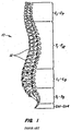
- the devices of the invention are designed to interact with the human spinal column 10 , as shown in FIG. 1 , which is comprised of a series of thirty-three stacked vertebrae 12 divided into five regions.
- the cervical region includes seven vertebrae, known as C1-C7 .
- the thoracic region includes twelve vertebrae, known as T1-T12 .
- the lumbar region contains five vertebrae, known as L1-L5 .
- the sacral region is comprised of five fused vertebrae, known as S1-S5, while the coccygeal region contains four fused vertebrae, known as Co1-Co4 .
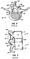
- FIG. 2 depicts a superior plan view of a normal human lumbar vertebra 12 .
- human lumbar vertebrae vary somewhat according to location, the vertebrae share many common features.
- Each vertebra 12 includes a vertebral body 14 .
- Two short boney protrusions, the pedicles 16, 16' extend dorsally from each side of the vertebral body 14 to form a vertebral arch 18 which defines the vertebral foramen.
- each pedicle 16 At the posterior end of each pedicle 16 , the vertebral arch 18 flares out into broad plates of bone known as the laminae 20 .
- the laminae 20 fuse with each other to form a spinous process 22 .
- the spinous process 22 provides for muscle and ligamentous attachment.
- a smooth transition from the pedicles 16 to the laminae 20 is interrupted by the formation of a series of processes.
- Two transverse processes 24, 24' thrust out laterally, one on each side, from the junction of the pedicle 16 with the lamina 20 .
- the transverse processes 24, 24' serve as levers for the attachment of muscles to the vertebrae 12.
- Four articular processes, two superior 26, 26' and two inferior 28, 28' also rise from the junctions of the pedicles 16 and the laminae 20 .
- the superior articular processes 26, 26' are sharp oval plates of bone rising upward on each side of the vertebrae, while the inferior processes 28 , 28' are oval plates of bone that jut downward on each side. See also FIG. 4 .
- the superior and inferior articular processes 26 and 28 each have a natural bony structure known as a facet.
- the superior articular facet 30 faces medially upward, while the inferior articular facet 31 (see FIG. 3 ) faces laterally downward.
- the facets 30 and 31 capped with a smooth articular cartilage and encapsulated by ligaments, interlock to form a facet joint 32 .
- the facet joints are apophyseal joints that have a loose capsule and a synovial lining.
- the facet joint 32 is composed of a superior facet and an inferior facet.
- the superior facet is formed by the vertebral level below the joint 32
- the inferior facet is formed in the vertebral level above the joint 32 .
- the superior facet of the joint 32 is formed by bony structure on the L5 vertebra (i.e., a superior articular surface and supporting bone 26 on the L5 vertebra)
- the inferior facet of the joint 32 is formed by bony structure on the L4 vertebra (i.e., an inferior articular surface and supporting bone 28 on the L4 vertebra).
- the angle formed by a facet joint located between a superior facet and an inferior facet changes with respect to the midline depending upon the location of the vertebral body along the spine.
- the facet joints do not, in and of themselves, substantially support axial loads unless the spine is in an extension posture (lordosis).
- the orientation of the facet joint for a particular pair of vertebral bodies changes significantly from the thoracic to the lumbar spine to accommodate a joint's ability to resist flexion-extension, lateral bending, and rotation.
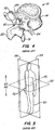
- FIG. 4 illustrates a posterolateral oblique view of a vertebrae 12, further illustrating the curved surface of the superior articular facet 30 and the protruding structure of the inferior facet 31 adapted to mate with the opposing superior articular facet.
- the position of the inferior facet 31 and superior facet 30 varies on a particular vertebral body to achieve the desired biomechanical behavior of a region of the spine.
- the overall spine comprises a series of functional spinal units that are a motion segment consisting of two adjacent vertebral bodies, the intervertebral disc, associated ligaments, and facet joints.
- functional spinal units that are a motion segment consisting of two adjacent vertebral bodies, the intervertebral disc, associated ligaments, and facet joints.
- a natural facet joint such as facet joint 32 ( FIG. 3 ) has a superior facet 30 and an inferior facet 31 .
- the superior facet of the joint is formed by the vertebral level below the joint, which can thus be called the “caudal” portion of the facet joint because it is anatomically closer to the tail bone or feet of the person.
- the inferior facet of the facet joint is formed by the vertebral level above the joint, which can be called the "cephalad" portion of the facet joint because it is anatomically closer to the head of the person.
- a device that, in use, replaces the caudal portion of a natural facet joint i.e., the superior facet 30
- a device that, in use, replaces the cephalad portion of a natural facet joint i.e ., the inferior facet 31
- a cephalad device a device that, in use, replaces the cephalad portion of a natural facet joint.
- embodiments of the spinal devices of the present invention include modular designs that are either or both configurable and adaptable.
- the various embodiments disclosed herein may also be formed into a "kit” or system of modular components that can be assembled in situ to create a patient specific solution.
- kit or system of modular components that can be assembled in situ to create a patient specific solution.
- imaging technology improves, and mechanisms for interpreting the images (e . g ., software tools) improve, patient specific designs employing these concepts may be configured or manufactured prior to the surgery.
- patient specific devices with integrally formed components that are pre-configured.
- a configurable modular device design allows for individual components to be selected from a range of different sizes and utilized within a modular device.
- size is to provide caudal and cephalad stems of various lengths.
- a modular implantable device design allows for individual components to be selected for different functional characteristics as well.
- One example of function is to provide stems having different surface features and/or textures to provide anti-rotation capability.
- Other examples of the configurability of modular implantable device of the present invention as described in greater detail below.
- Implantable devices of the present invention are configurable such that the resulting implantable spinal device is selected and positioned to conform to a specific anatomy or desired surgical outcome.
- the adaptable aspect of embodiments of the present invention provide the surgeon with customization options during the implantation or revision procedure. It is the adaptability of the present device systems that also provides adjustment of the components during the implantation procedure to ensure optimal conformity to the desired anatomical orientation or surgical outcome.
- An adaptable modular device of the present invention allows for the adjustment of various component-to-component relationships.
- One example of a component-to-component relationship is the rotational angular relationship between a crossbar mount and the crossbar.
- Other examples of the adaptability of modular device of the present invention as described in greater detail below.
- Configurability may be thought of as the selection of a particular size of component that together with other component size selections results in a "custom fit" implantable device. Adaptability then can refer to the implantation and adjustment of the individual components within a range of positions in such a way as to fine tune the "custom fit" devices for an individual patient.
- the net result is that embodiments of the modular, configurable, adaptable spinal device and systems of the present invention allow the surgeon to alter the size, orientation, and relationship between the various components of the device to fit the particular needs of a patient during the actual surgical procedure.
- anatomical references of the body 50 with respect to which the position and operation of the devices, and components thereof, are described.
- Devices positioned within the body can be positioned dorsally 70 (or posteriorly) such that the placement or operation of the device is toward the back or rear of the body.
- devices can be positioned ventrally 72 (or anteriorly) such that the placement or operation of the device is toward the front of the body.
- Various embodiments of the spinal devices and systems of the present invention may be configurable and variable with respect to a single anatomical plane or with respect to two or more anatomical planes.
- a component may be described as lying within and having adaptability or operability in relation to a single plane.
- a stem may be positioned in a desired location relative to an axial plane and may be moveable between a number of adaptable positions or within a range of positions.
- the various components can incorporate differing sizes and/or shapes in order to accommodate differing patient sizes and/or anticipated loads.
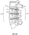
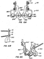
- FIG. 6A is a view of a portion of the spine 10 having a spinal fusion implant 100 (such as the spinal fusion rod and screw system commercially available from SeaSpine corporation) from a side view positioned in the sagittal plane.
- the spinal implant 100 has a rod 110 which is anchored to the spine 10 with one or more anchors 120 , such as bone screws that penetrate the vertebral body 14.
- the anchors 120 are fixed to the rod 110 via attachment mechanisms 115 .
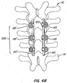
- FIG. 6B is a dorsal view of a portion of the spine 10 having a spinal implant 100 .
- the spinal implant has a pair or rods 110 , 110 which are anchored to the spine 10 with one or more anchors 120 (shown in FIG. 9A ) fixed to the rods 110, 110 ' via attachment mechanisms 115 .
- spinal fixation systems can also be employed without departing from the scope of the invention.
- systems using cables to stabilize the spine instead of rods can be employed.
- the device can be used in combination with fixation systems positioned anteriorly, posteriorly, and laterally with respect to the spinal column.
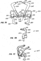
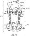
- FIG. 7A is a posterior view of an anchorable facet replacement device 200 according to one embodiment of the present invention.
- the device 200 includes a crossbar 205 , a pair of cephalad arms 220, 220' and a pair of connectors 230, 230 ' .
- the facets 30 and 31 of the vertebral body are replaced by the cooperative operation of the crossbar 205 , the cephalad arms 220 , 220 ' and the adaptable crossbar mounts 276 that join the cephalad arms 220, 220' to the crossbar 205 , interacting with the caudal device 250 .
- the components of the cephalad implantable device 200 are designed to provide appropriate configurability and adaptability for the given disease state, patient specific anatomy and spinal level where the implant occurs.
- the crossbar 205 has a first end 210 and a second end 215 .
- the crossbar 205 can be formed from a two piece bar where the first end 210 is attached to a threaded male portion having threads (not shown).
- the crossbar second end 215 can be attached to a threaded female portion sized to receive the threads. It is contemplated that the threaded ends allow for the width of the crossbar to be adjusted to mate with the width between caudal bearings 250 .
- crossbar 205 could include a series of solid crossbars of varying widths and/or thicknesses, or an adjustable crossbar having some form of locking or biasing mechanism (such as a springloaded tensioner or detent mechanism, etc .), as would be appreciated by those of skill in the art.
- end 210 can be configured to have a threaded male portion (instead of female portion) that fits within a female threaded portion of the crossbar 205 without departing from the scope of the invention.
- a pair of cephalad arms 220 are also illustrated in the exemplary embodiment of the anchorable, adaptable implantable device 200 of the present invention.
- Each cephalad arm 220, 220' includes a bone engaging end 225 , 225' and an end 240, 240' adapted to couple to the crossbar 205 .
- the caudal end 240 adapted to engage the crossbar 205 includes an arm 245 and an elbow 247 .
- the caudal end 240 is attached to the crossbar using the crossbar mount 276 .
- the bone engaging cephalad end 225 includes a cephalad stem 230 and a distal tip 235 .
- the cephalad stem 230 and the distal tip 235 are threaded or otherwise configured to engage the bone.
- the distal tip 235 could be formed integrally with the cephalad stem 230 , of the same or a different material as the cephalad stem 230 .
- the surface of the cephalad stem 23 0 can be a textured surface or any other modified surface such as, for example, a surface that assists or promotes bony in-growth.
- the crossbar mount 275 is a connection structure to couple the cephalad prosthesis elements 220 to the crossbar 205 .
- the crossbar mount 275 includes a cephalad arm engaging portion 272, a crossbar engaging portion 274 and a fixation element 276.
- Embodiments of the crossbar mount 275 provide adaptability between the cephalad prosthesis elements 220 and the crossbar 205 and the loading characteristics of the crossbar ends 10, 215 and the caudal prosthesis 250 .
- a pair of caudal bearing elements 250 are also illustrated in the exemplary embodiment of the configurable and adaptable cephalad stabilization device 200 of the present invention.
- Each of the caudal bearing elements 250 includes a caudal cup 251.
- the caudal cup 251 includes a surface 255 adapted to receive a crossbar end and a surface to engage the caudal stern head engaging surface.
- Caudal connectors 230, 230 ' are provided to connect the implantable device 200 to the rods 110, 100 ' of the spinal implant 100 below the connection mechanism 115 .
- the clamping mechanism 230 can attach to various portions of the spinal implant 100 , including the rods 110 , 110 ' or the connection mechanism 115 .
- clamping mechanisms 230, 230' can further be adapted to lock onto the spinal implant 100 by providing an additional connection mechanism 231 such as a bolt.
- FIG. 7B illustrates the implantable device 200 from a side view
- FIG. 7C illustrates the device 200 from a perspective view.
- the device can be configured to function with only a single cephalad arm, thus allowing for a 3-point fixation mechanism, that in-turn is connected to the spinal fusion device.
- the cephalad arm 220 can be coupled to the cross-bar 205 such that the length of the arm 220 from the bone engaging end 225 to the cross-bar engaging end 240 crosses the midline of the vertebra along the vertical length of the sagittal 54 plane.
- Other attachment mechanisms can be provided without departing form the scope of the invention.
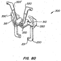
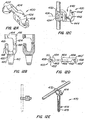
- FIG. 8A is a posterior view of an anchorable facet replacement device 300 according to an alternate embodiment of the present invention.
- the device 300 includes a crossbar 305 , a pair of cephalad arms 320, 320 ' and a pair of cephalad connectors 330, 330 ' .
- the facets 30 and 31 of the vertebral body are replaced by the cooperative operation of the crossbar 305 , the cephalad arms 320, 320 ' and the adaptable crossbar mounts 275 that join the cephalad arms 320, 320 ' to the crossbar 305 join the device to an implant, interacting with the caudal device 350 .
- the components of the caudal implantable device 300 are designed to provide appropriate configurability and adaptability for the given disease state, patient specific anatomy and spinal level where the implant occurs.
- the crossbar 305 has a first end 310 and a second end 315 .
- the crossbar 305 can be formed from a two piece bar where the first end 310 is attached to a threaded male portion having threads (not shown).
- the crossbar second end 315 can be attached to a threaded female portion sized to receive the threads. It is contemplated that the threaded ends allow for the width of the crossbar to be adjusted to mate with the width between caudal bearings 350 .
- crossbar 305 could include a series of solid crossbars of varying widths and/or thicknesses, or an adjustable crossbar having some form of locking or biasing mechanism (such as a springloaded tensioner or detent mechanism, etc .), as would be appreciated by those of skill in the art.
- end 310 can be configured to have a threaded male portion (instead of female portion) that fits within a female threaded portion of the crossbar 305 without departing from the scope of the invention.
- a pair of caudal bearing elements 350 are also illustrated in the exemplary embodiment of the configurable and adaptable device 300 of the present invention.
- Each of the caudal bearing elements 350 includes a caudal cup 351 and a fixation element 360.
- the caudal cup 351 includes a surface 355 adapted to receive a crossbar end and a surface to engage the caudal stem head engaging surface.
- the fixation element 360 includes a caudal stem 365 and a distal tip 370 .
- the distal tip 370 can be formed integrally with the caudal stem 365 , of the same or a different material as the caudal stem 365 .
- the caudal stem 365 and distal tip 370 can be threaded or otherwise configured to engage.
- Cephalad connectors 330, 330 ' are provided to connect the implantable device 300 to the rods 110 , 100 ' of the spinal implant 100 below the connection mechanism 115 .
- the clamping mechanism 330 can attach to various portions of the spinal implant 100 , including the rods 110, 100' or the connection mechanism 115 .
- Other devices can be provided that are attached to all or part of the spinal implant 100 , including cross-connectors and/or lateral rod connectors (not shown), or combinations thereof.
- the clamping mechanisms 330 , 330 ' can further be adapted to lock onto the spinal implant 100 by providing an additional connection mechanism 331 such as a bolt or a screw.
- FIG. 8B illustrates the implantable device 300 from a side view
- FIG. 8C illustrates the device 300 from a perspective view.
- the device can be configured to provide a single caudal arm, thus providing a 3-point fixation mechanism that, in turn, is connected to the spinal fusion device.
- the caudal arm 320 can be coupled to the cross-bar 305 such that the length of the arm 320 from the spinal fusion engaging end to the cross-bar engaging end 340 crosses the midline of the vertebra along the vertical length of the sagittal 54 plane.
- FIG. 8D illustrates an implantable device 300 suitable for use in a fusion system wherein the fusion system is being converted mid-length to provide for motion at a target joint.
- the device 301 has a cross-bar 305 which engages two caudal cups 350 on either end.
- Caudal arms 320, 320' are provided to connect the device to a spinal fixation device (such as device 100).
- Cephalad connectors 230, 230' are provided to connect the device to a second spinal fixation device.
- the implantable device 301 provides an articulable device between two implanted devices that stabilize the spine both in the caudal and cephalad direction.
- Either of the caudal arms 320, 320' or the cephalad connectors 230, 230' can be configured to engage the spinal fusion device 100 along the rod 110, the anchors 120 or the attachment mechanisms 115. Configurations can include, providing an aperture to receive, for example, a screw which engages the fusion device 100, or configuring the arm 320, 320' or connector 230, 230' to hook around the fusion device, e . g ., around the rod.
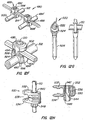
- FIGS. 9A, 9B and 9C illustrate a spinal fusion implant 100 and facet replacement device 200 (see FIG. 7A ) implanted on a portion of a spine 10.
- the spinal fusion implant 100 has been depicted at an angle relative to the facet replacement device 200.
- the orientation of the spinal fusion implant 100 and the facet replacement device 200 can be varied, as desired.
- the anchoring mechanism of the spinal fusion implant 100 have not been depicted in each depiction to avoid obscuring the invention.
- the design of the device 200 is such that it can be implanted during an open surgical procedure, or can be implanted through less-invasive and/or minimally-invasive means.
- the various components of the device 100 can be delivered percutaneously. Moreover while various components described can be implanted into the pedicles, these components, and variations thereof, can be implanted or secured to the pedicles, the lamina, the vertebral body, or combinations thereof.
- FIGS. 10A , 10B and 10C illustrate an alternative system 98 for achieving spine stabilization and facet function restoration.
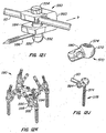
- FIG.11A illustrates an implanted system 97 from the dorsal view.
- Two or more vertebra are stabilized with a spinal fusion implant 100 and the facet joint to the next adjacent cephalad vertebra is partially or completely replaced by a device 200 while the facet joint to the next adjacent caudal vertebra is partially or completely replaced by a device 300.
- FIG.11B illustrates the implanted system 97 from the side view;
- FIG. 11C illustrates the system from a perspective view.
- the length of the spine stabilization system 100 employed can vary depending upon the number of vertebra to be fused.
- the device of FIG. 8D can also be employed in a system, such as 97 , to provide a combination of fusion with articulation.
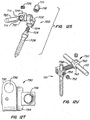
- FIG. 12A illustrates a connector 400 having a bearing 402 connected to an arm 404.
- the connector 400 has an arm holder 406 that connects the arm 404 to a sleeve 410.
- the connector illustrated in FIG. 12B enables a spinal implant, such as those depicted above, to be anchored to the spine 10 by positioning a portion of the vertebral body within the hook 410.
- the rod 110 (shown in FIGS. 7-8 ) of the spinal implant can then be inserted laterally through the opening 412 defined between the lateral portion 414 of extension 416 and flange 418 of connector portion 420.
- the rod may then be axially displaced along the U-shaped channel 422.
- FIG. 12C illustrates another internal fixation device suitable for use with this invention.
- the internal fixation device 430 attaches to a fixation rod 110, 110' and comprises a hook 432 with a screw device 434 with an axis 436.
- the hook 432 has an actual hook element 438 and a shackle element 440 which grips a portion of the spine.
- the shackle element 440 is used to fasten the fixation rod 110 and the hook 432 on each other.
- the shackle element 440 forms a groove with a groove bottom 442 , against which the fixation rod 110, 110 ' rests, and two lateral walls 444, 444 ' following the groove bottom 442 .
- the two lateral walls 444, 444' of the shackle element 440 are clamped together by means of the screw device having the axis 436 by means of which the fixation rod 110, 110' can be clamped in place with its area received in the shackle element 440 .
- FIG. 12D illustrates a transverse connector 450 suitable for use with the present invention.
- the connector 450 joins two elongated spinal stabilizers 452, 452 ', (but which could also comprise plates), fixed to a number of vertebrae by means of anchoring members which are not shown.
- the transverse connector has a linking assembly having a first 454 and a second part 456 which each have an end portion terminating in a clamp 458, 458 '.
- a variety of clamping structures could be used. They can be the same or different. For example, the clamp on one side could be closed while the clamp on the opposing side could be open. However, preferably, the clamps each include a recess 458, 458 ' which receive a respective rod.
- Setscrews 461 can be employed and received in threaded bores each terminating in a beveled area 462, 462 ' which biases the rod into a retaining contact with the recess.
- the longitudinal axis of the setscrew is offset from the longitudinal axis of the rod receiving recess so that the setscrew will bias the rod into the recess.
- the setscrews may include internal hexes, or other suitable torque driving means, for tightening.
- the recesses 458, 460 are both open toward a central medial line or toward each other. This arrangement can be used for initial placement of the connector on the rod 110 ( FIG. 6 ).
- the connector assembly can be placed onto the rods and then tightened with respect to the length.
- the second member 456 of the transverse connector includes a bore 462 , which receives an extension portion 464 which extends outwardly from the clamp 458 of the first part 454 .
- the extension can move in and out of the bore 462 to contract or expand the length of the space connected and the extension 464 can rotate in the bore 462 to change the relative angle of the openings of the rod recesses of the clamps to accommodate a varying relative angle of the longitudinal axis of the rods 110.
- the first and second members, 454, 456 can include a limit mechanism such as a flanged end on the extension 464.
- this flanged end is inserted into a vertical keyway 466 which is a vertical slot in the first member having an enlarged opening that is slightly larger than the diameter of the annular flange, and which will accommodate entry of the larger diameter flanged end.
- An undercut can be provided on either side of the keyway to allow for captured movement of the flanged end in the keyway, but allow for restriction against movement out of the keyway 466 .
- a vertical slotted area is slightly wider than the diameter of the extension.
- FIG. 12E illustrates a bar 110 with a threaded screw connector 470 .
- a hollow connector 472 is provided to engage the rod 110.
- a fastener 474 pivotally connects the bone anchoring bolt 476 , having threads 478 , such that the connector 470 can attach a bar or cable 110 to a bone.
- FIG. 12F illustrates a perspective view of a mounting device 480 .
- the device 480 comprises a connector 482 with two screws 484, 484' adapted to form a screw-nut link by engaging the duct 486 of the head 488 of the connector.
- the connector has two vertical plane faces 490 comprising a front face and a rear face, which faces are substantially parallel and extend continuously over the full height of the connector.
- the connector also has two horizontal plane faces comprising a top face and a bottom face 492, 492' that are parallel to each other and substantially perpendicular to the above-mentioned vertical faces 490.
- the connector has a generally cylindrical duct 486 extending parallel to the front and rear faces 490 , halfway between them, and perpendicular to the top and bottom faces 492 , 492 ' through which it opens out.
- the connector is axially symmetrical about the axis of the duct 486 .
- the connector has two slots 494, 494' extending generally parallel to the top and bottom faces 492, 492' in two side faces 496 of the connector that extend perpendicularly to the front and rear faces 490 .
- Each slot 494, 494' is generally of channel section being defined by a top face 498 parallel to the top face 492 of the connector, a web face parallel to the side faces 496 of the connector, and a bottom face 498' facing the top face 498 and extending perpendicularly to the front and rear faces 490 while being slightly inclined towards the inside of the connector.
- the angle between the top and bottom faces 498, 498' of the slot can lie in the range 2 to 10°, for example.
- the slots 494, 494' co-operate with the duct 486 which extends between them to define a housing for receiving a crossmember 500 , as described below.
- the slots 494, 494' define two junctions between which the duct 486 and the housing extend.
- a portion of the connector extending above the junctions forms a head 502.
- the two side faces 496 on the head 502 are shaped like two sectors of a common cylinder that is coaxial with the duct 486.
- the connector has a bottom cylindrical face 504 contiguous with the bottom face 498 of the connector, perpendicular to the duct 486, and halfway between the two side faces 496. Between them, the slots 494, 494' and the cylindrical face 504 define two jaws 506, 506' each connected to the head 502 by the two junctions.
- the connector On each junction, the connector has a notch 508 extending away from the jaws 506, 506' towards the head 502.
- the diameter of the duct 486 is smaller in the head 502 than in the remainder of the connector. Inside the head 502, the duct 486 has a thread.
- the device has two screws 484 each adapted to form a screw-nut link by engaging in the duct 486 of the head 502 of a respective connector.
- Each screw 484 has a hexagonal socket 510 for receiving a hexagonal key for turning the screw 484 received in the duct 486.
- the device has two rectilinear longitudinal rods 512, 572' for extending along the backbone of a patient, each being fixed to the vertebrae by anchor members using techniques known in the art.
- the two rods 512, 512' typically have a circular profile as illustrated with a diameter the same as the cylindrical face 504 between the jaws.
- the jaws 506, 506' are adapted to make surface-on-surface contact with the rod.
- the cylindrical faces 504 of the jaws together extend over a circular arc of total extent exceeding 180° and selected as a function of the properties of the material of the connector so as to enable the jaws 506, 506' to be engaged on the rod 512, 512' by being snap-fastened thereon.
- the cylindrical faces 504 of the jaws present a geometrical outline which extends beyond the bottom face 492' of the connector 482.
- the rod projects beyond the jaws in a radial direction.
- the device has a rectilinear crossmember 514 of generally rectangular section adapted to be received in the housings, passing right through the connectors 482.
- FIG. 12G illustrates another connection system 520.
- a rod 110 is received through aperture 522 in a pivotal head 524 attached to an anchoring dowel 526 for anchoring the device 520 to the bone.
- the positioning and locking device 530 is made up of an upper jaw member 532 and a lower jaw member 534 having opened faces which are machined with assembly notches 536 to allow one to be positioned and pivoted against the other, leaving an opening 538 at the opposite end.
- a bushing, or hollow shaft, 540 passes through the two jaws 532, 534 at right angles and then through the opposite end of the jaws, with respect to the gripping jaw opening.
- Bushing 540 at its upper part 542, has the shape of a cone frustum with slots 544 which start from this upper part 542 and run in the direction of the axis of the bushing to end about halfway down the length thereof.
- bushing 540 The lower part of bushing 540 is threaded at 546 and is screwed into a nut 548 which clamps the two jaws 532, 534 together.
- a spring in the form of a staple 550 or bent wire is housed inside holes 552 each made in each one of the jaws 532, 534 also on the opposite side to the opening of the gripping jaw.
- Upper jaw 532 has a conical recess in its upper part and a cylindrical bore to accommodate bushing 540 and lower jaw 534 has a bore which has two opposed flat surfaces to play a part in holding bushing 540 in place especially against rotation, these flat surfaces not being depicted in the drawing.
- Bushing 540 can have a smaller diameter in its threaded lower part 546 and in its central part has two opposed flat surfaces, not shown in the drawing, which engage the flats on lower jaw 534 to prevent bushing 540 from rotating relative to the jaws and allow the nut to be locked. Between bushing 540 and the bores of jaw 534, 536 there is a clearance that allows the jaws device 530 to be pivoted outwardly against the face of staple spring 550 , prior to the tightening operation. The clearance allows the jaws 532 , 534 to be parted just enough for clipping an element between the faces of each jaw, for example, onto a rod or a hoop along which device 530 can slide and therefore change position.
- a rod 110 may be inserted into bushing 540 and locked in position by the clamping action of the conical position of the upper part of bushing 540 which deforms inwardly as nut 548 is tightened pulling the bushing downwardly into the conical recess of upper jaw 532 .
- This rod 110 may remain fixed in a concrete assembly position so that one can adjust the relative positions of all the elements of the device prior to the final operation of tightening the assembly.
- FIG. 12I is a perspective view of the constructed clamp 550 with a small cut-away to show the junction between the pin connector 552 and the connecting rod 110.
- Tightening the bolt 554 draws the pin 556 against the distal outer surface 558 of the clamp body 560. This action braces the pin against the clamp preventing the rotation of the pin connector 552 and thus the pin 556 .
- the pin 556 is prevented from moving axially with respect to connector 552. Tightening the bolt 554 additionally draws the rod-engaging surface 580 of the connector 552 into engagement with the connecting rod 110. This interference has a number of effects that further prohibit any movement of the tightened clamp 550.
- friction between the rod-engaging surface 580 and the outer surface of the rod 110 further prevents any rotation of the pin connector 552. Additionally, the force exerted by the pin connector at this junction pushes the rod 110 in the direction of arrow b. This ensures that the rod 110 is seated against the back wall 582 of the slot 584 providing a good rigid mechanical junction between the connecting rod 110 and the clamp body 560 preventing rotation of the clamp body around or sliding along the connecting rod 110 .
- the clamp body 560 does not substantially squeeze-down on or close over the connecting rod when the bolt 554 is tightened. It is only the interference between the rod-engaging surface and the rod 110 that prevents movement between the rod 110 and clamp 550 .
- FIG. 12J illustrates an attachment mechanism 570 has a threaded nut 572 having female threads 574 for engaging the shaft 576 of an anchoring shaft 578.
- the threaded nut 572 has a clamp 580 for engaging a rod 110.
- the clamp 580 forms an adjustable aperture 582 .
- the aperture 582 is adjusted by tightening a fastener 584.
- FIG. 12K illustrates a bone bolt 590 suitable for use with the invention.
- Bone bolt 590 is shown attached to a clamp 592 with the longitudinal axis L1
- clamp 592 is shown attached to a spinal implant rod 594 with a longitudinal axis L2.
- Clamp 592 includes a clamp bolt 596 , an arm 598 , a rod interface washer 600, a set screw 602, and a nut 604.
- Clamp bolt 596 has an aperture 606 for receiving rod 594 , and while the aperture is shown closed around rod 594, it will nevertheless be understood that an open-sided aperture may also be used to permit top-loading of rod 594 into clamp 592.
- Set screw 602 is inserted through a threaded opening 608 and into aperture 606 in clamp bolt 596 so as to allow set screw 602 to push against rod 594.
- Arm 598 has a bore 610 for receiving bone bolt 590. Arm 598 is simultaneously tightened to clamp 592 when set screw 602 is tightened against rod 594.
- rod 594 pushes against rod interface washer 600 , which pinches arm 598 between rod interface washer 600 and stop 612. In this manner, set screw 602 acts as a compression member to tighten clamp 592 and achieve substantial fixation of arm 598 to rod 594.
- FIG. 12L depicts fasteners 620 suitable for use in the invention.
- the fastener 620 has an aperture 622 for receiving a rod 110 (not shown) and is adopted to allow the diameter of the aperture 622 to increase and decrease in order to facilitate engaging the rod 110.
- a bolt 624 is provided to communicate through a second aperture 626 to decrease the aperture 622 that received the rod.
- FIG. 12M retainer assembly 630 includes a set screw 632 and a generally rectangular retainer block 634 into which angular member 636 and rod 110 extend.
- Block 634 has a rod passage 638 which receives rod 110.
- Rod 110 (not shown) can have a substantially circular cross-section; however, rods having various other cross-sections, such as hexagonal or oval cross-sections, could be used with corresponding modifications to rod passage 638.
- Block 634 also includes a transverse passage 640 which receives inner end portion 642 of angular member 636 and communicates with rod passage 638.
- Transverse passage 640 includes a plurality of mating surfaces 644 which engage similarly shaped retaining surfaces or teeth 646 that project radially outwardly from inner end portion 642 of angular member 636. Meshing engagement between mating surfaces 644 on block 634 and teeth 648 on inner end portion 642 prevents rotational movement of angular member 636 about a longitudinal central axis 650 of inner end portion 642. It is understood that mating surfaces of various shapes may be formed in transverse passage 640 to receive similarly shaped retaining surfaces formed on block 634.
- FIG. 12N illustrates another attachment mechanism 660.
- Pincers 662 attached to the vertebras, formed by two curved claws with opposite concavities, one of which 664 forms part of the body 666 of the pincer and the other 668 independent, with a cylindrical lateral prolongation 610 which on passing tightly through the body 666 of the pincer allows it to make axial or turning displacements to adapt the relative position of the two claws to the shape and sizes of the zone of the vertebra where it is fastened.
- FIG. 12O illustrates yet another attachment mechanism 680.
- a crossbar 682 is provided with a clamping mechanism 684 having a sizable aperture 686.
- the sizable aperture 686 is adjustable by adjusting screw 688.
- the aperture 686 is configured to, for example, receive a rod 110 .
- FIG.12P illustrates an alternate mechanism 640.
- a pair of parallel rods 642, 642' are provided.
- the first parallel rod 642 is integrated with a connector 644 for the second parallel rod 642' .
- the second parallel rod 642' can be fed through an aperture 646 on the connector 644.
- a nut 648 is provided to secure the second nut 642' in the aperture 646.
- FIG. 12Q illustrates a connector 770 having a rod 110 connected to a crossbar 772.
- the rod is secured through an aperture 774.
- a nut 776 is provided to secure the rod 110.
- FIG. 12R illustrates a connector assembly 780 suitable for use with the invention from a perspective view, an end view and a top view.
- the assembly attaches spinal implant rod 110 with a longitudinal axis L1 to the shaft of a vertebral anchor with the longitudinal axis.
- Connection assembly 780 includes a bolt 782, a clevis 784, a rod interface washer 786, and a set screw 788.
- Bolt 782 has an aperture 790 for receiving a rod 110 in a spinal implant system. While a closed aperture is depicted, it will be appreciated than an open-sided aperture may also be used to permit top loading the of the connector rod.
- Set screw 786 is inserted through a threaded opening 792 in bolt 786 and into aperture 790 to allow set screw 786 to push against rod A .
- Clevis 784 is a u-shaped piece with a bore 794 for receiving a vertebral anchor or bolt B and is simultaneously tightened when set screw 788 is tightened against rod A .
- the shaft B may be roughened and the interior of clevis 784 may be correspondingly roughened to increase friction between the pieces.
- rod A pushes against rod interface washer 786. This force pinches the ends 796 and 798 of clevis 784 together between rod interface washer 786 and stop 800 , which tightens clevis 784 together between rod interface washer 786 and stop 790.
- FIG. 12s depicts a multiaxial connector 700 suitable for the invention.
- the connector 700 has a first connecting element 702 perforated with a bore 704 designed to receive the second threaded part 706 of the fixing screw 708 , another bore 710 comprising in its inner part an annular track 712 with spherical profile and a slot 714 passing through the bore 704 to emerge inside the bore 710 at the annular track 716 , a second connecting element 718 perforated with a bore 720 designed to receive the lining rod 722 of a threaded hole 724 co-operating with a clamping screw 726 for locking the rod in translation and linking means 728 forming a ball joint enabling the first and second elements to be coupled together such that the elements can pivot relative to each other to present the linking rod 729 in specific angular positions and to laterally offset the linking rod relative to the pivoting centre of the elements.
- FIG. 12T illustrates a connection assembly 730 having a longitudinal member 732 and a housing 734.
- Longitudinal member 732 has an aperture 736 for receiving a rod 110 , for example in a spinal system. Open sided apertures can be used to permit top loading of the rod.
- a threaded opening 738 is provided to communicate with a set screw 740.
- the housing 734 has a passageway 742 for receiving a shaft or shank of a vertebral anchor.
- FIG. 12U illustrates a connection assembly 750 used with an offset connector or spindle.
- the assembly 750 has aperture threaded bolt 752 for connection to bone.
- the fence bolt 752 fits within an aperture 754 of an anchor 756.
- a cross member 758 connects the anchor 756 to a rod holder 760.
- a rod 110 fits within an aperture 762 of the rod holder.
- a set screw 764 is provided to fix the location of the rod in the aperture.
- a second set screw 766 is provided to fix the location of the fence bolt 752 within the aperture 754 of anchor 756 .
- connectors that would be suitable for use in the invention include, for example, those described in U.S. Patent Nos. 6,231,575 , 6,309,391 , 6,340,361 , 6,342,054 , 6,368,320 , 6,749,361 ; U.S. Patent Publication Nos. 2002/0049446 , 2002/0042613 , 2002/0013585 , 2002/0013588 , 2002/0082601 ; European Patent Nos. 1205152 , 1103226 ; PCT Patent Publication Nos. WO 01/30248 , WO 02/34150 , WO 01/67972 , WO 02/02024 , WO 01/06939 ,
- FIG. 13 a flow chart depicting a method for using the devices according to the invention is depicted.
- an incision is created 800 to access a target location of the spine.
- this devices of this application can be implanted concurrently with the implantation of a spinal fusion device, such as a rod and screw, or in a subsequent procedure. If the devices are implanted concurrently with the fusion device, then the physician would proceed with first implanting the spinal fusion device 801 . Alternatively, where the fusion device has already been implanted ( e . g ., where this procedure revises the prior surgical procedure), then the physician accesses the implanted fusion device 802 immediately following creating the incision 800 .
- the physician can select one or more adjacent level arthroplasty devices 804 to use with the implanted spinal fusion device. Once the devices are selected 804 , the devices are then implanted 806 .
- the physician can choose a first adjacent level arthroplasty device, implant it in conjunction with the spinal fusion device and then select a different device based on, for example, experience or in situ appearance of the suitability of the device. Additionally, adjustments to the connection of the adjacent level arthroplasty device can be made.
- the incision is then closed 808 .
- FIG. 14 depicts the flow chart for an alternate method for using the devices of the present invention, particularly well suited for revision of an already-fused functional spinal unit, to partial or full natural motion.
- an incision is created 900 to access a target location of the spine.
- the spinal fusion device can be implanted 901 at that time or during a previous procedure. As discussed, this procedure is well suited for a subsequent procedure.
- the physician then exposes at least a portion of the spinal fusion instrumentation 902 . Thereafter, the physician can remove and/or modify the components of the existing spinal fusion instrumentation. Removal and/or modification includes the resecting of individual fusion components, such as rods.
- the physician can access the intervertebral disk space 903 to separate any arthrodesis across the disk space as well as remove any fusion cages and/or other associated intervertebral fusion devices (including intervertebral spacer and/or dynamic stabilization devices) 904 .
- the physician can implant an artificial disk or nucleus replacement 905 .
- the physician can select one or more adjacent level arthroplasty devices 906 to use with the remaining components of the spinal fusion instrumentation. Once the devices are selected 906 , the devices are then implanted 907 .
- the physician can choose a first adjacent level arthroplasty device, implant it in conjunction with the spinal fusion device and then select a different device based on, for example, experience or in situ appearance of the suitability of the device. Additionally, adjustments to the connection of the adjacent level arthroplasty device can be made without departing from the scope of the invention. Once the physician is satisfied with the selection, the incision is then closed 908 . It should also be appreciated that the present method could be used to revise the fusion of a single functional spinal unit, or could be used in any portion or location of a spinal fusion spanning multiple spinal levels.
Claims (24)
- Implantierbare Facettenarthroplastievorrichtung (300) zum Verknüpfen mit einem ersten Wirbel und einem zweiten Wirbel, Folgendes umfassend:(a) eine Querstange (305) mit einem ersten Ende (310) und einem zweiten Ende (315);(b) ein Paar kaudaler Lagerelemente (350), die mit dem zweiten Wirbel verbindbar sind, wobei das Paar kaudaler Lagerelemente die Enden der Querstange derart aufnimmt, dass die kaudalen Lagerelemente bezogen auf die Querstange artikulierbar sind;(c) eine erste Komponente (320) mit einem ersten Befestigungsmechanismus, angepasst, um an eine erste Stelle einer an einem ersten Wirbel befestigten Spondylodesevorrichtung (100) zu befestigen zu sein, und einem zweiten Befestigungsmechanismus (275), angepasst, um mit der Querstange in Eingriff zu treten; und(d) eine zweite Komponente (320') mit einem ersten Befestigungsmechanismus, angepasst, um an eine zweite Stelle einer an dem ersten Wirbel befestigten Spondylodesevorrichtung zu befestigen zu sein, und einem zweiten Befestigungsmechanismus (275), angepasst, um mit der Querstange in Eingriff zu treten.
- Implantierbare Facettenarthroplastievorrichtung nach Anspruch 1, ferner eine Spondylodesevorrichtung (100) umfassend.
- Implantierbare Facettenarthroplastievorrichtung nach Anspruch 2, wobei die Spondylodesevorrichtung (100) Folgendes umfasst: ein Paar länglicher Elemente (110), die konfiguriert sind, sich entlang eines Abschnitts der Wirbelsäule neben einem kranial gelegenen Wirbel und einem kaudal gelegenen Wirbel zu erstrecken und mehrere Befestigungsmechanismen (115, 120) zum Anbringen der Spondylodesevorrichtung an dem kranial gelegenen Wirbel und dem kaudal gelegenen Wirbel.
- Implantierbare Wirbelsäulenrestorationsvorrichtung, Folgendes umfassend:(a) ein längliches Element (110), konfiguriert, um sich entlang eines Abschnitts einer Länge einer Wirbelsäule neben einem kranial gelegenen Wirbel und einem kaudal gelegenen Wirbel zu erstrecken;(b) einen Befestigungsmechanismus (115, 120), angepasst, um das längliche Element an einem Abschnitt der Wirbelsäule zu befestigen;(c) ein Paar von Facettenarthroplastieelementen, wobei jedes ein kaudales Lagerelement (250, 350) aufweist;(d) eine Querstange (205, 305) mit einem ersten Ende (210, 310) und einem zweiten Ende (215, 315), bemessen, um einen Abschnitt des Wirbelkörpers zu überspannen, und angepasst, um die Facettenarthroplastieelemente an dem ersten Ende und dem zweiten Ende derart aufzunehmen, dass die Facettenarthroplastieelemente bezogen auf die Querstange artikulierbar sind; und(e) einen Verbinder (230, 230', 320, 320'), angepasst, um die Facettenarthroplastieelemente mit dem länglichen Element zu verbinden.
- Implantierbare Wirbelsäulenrestorationsvorrichtung nach Anspruch 4, ferner umfassend einen Arm (220) mit einem Knocheneingriffsende (225), angepasst, um an einem ersten Ende an einem Wirbel befestigt zu werden, und einem Ende (240), angepasst, um an einem zweiten Ende an der Querstange (205) befestigt zu werden.
- Implantierbare Wirbelsäulenrestorationsvorrichtung nach Anspruch 5, wobei der Arm (220) konfiguriert ist, mit einem kaudal gelegenen Wirbelkörper in Eingriff zu treten.
- Implantierbare Wirbelsäulenrestorationsvorrichtung nach Anspruch 5, wobei der Arm (220) konfiguriert ist, mit einem kranial gelegenen Wirbelkörper in Eingriff zu treten.
- Implantierbare Wirbelsäulenrestorationsvorrichtung nach Anspruch 5, ferner umfassend einen zweiten Arm (220') mit einem ersten Ende (225'), das angepasst ist, an einem ersten Ende mit einem Wirbelkörper in Eingriff zu treten, und einem zweiten Ende (240'), das angepasst ist, mit der Querstange (205) in Eingriff zu treten.
- Implantierbare Wirbelsäulenrestorationsvorrichtung nach Anspruch 8, wobei der erste Arm (220) bezogen auf den zweiten Arm (220') artikulierbar ist.
- Implantierbare Wirbelsäulenrestorationsvorrichtung nach Anspruch 4, wobei die Querstange (205, 305) bemessen ist, einen Abschnitt eines Wirbelkörpers zwischen einer linken Lamina und einer rechten Lamina zu überspannen.
- Implantierbare Wirbelsäulenrestorationsvorrichtung nach Anspruch 4, wobei die Querstange (205, 305) bemessen ist, einen Abschnitt eines Wirbelkörpers zwischen einem linken Pediculus und einem rechten Pediculus zu überspannen.
- Implantierbare Wirbelsäulenrestorationsvorrichtung nach Anspruch 4, wobei die Querstange (205, 305) ferner angepasst ist, eine einstellbare Breite aufzuweisen.
- Implantierbare Wirbelsäulenrestorationsvorrichtung nach Anspruch 4, wobei das Facettenarthroplastieelement (250, 350) bezogen auf die Querstange (205, 305) positioniert ist, um eine symmetrische anatomische Lösung bereitzustellen.
- Implantierbare Wirbelsäulenrestorationsvorrichtung nach Anspruch 4, wobei das Facettenarthroplastieelement (250, 350) bezogen auf die Querstange (205, 305) positioniert ist, um eine asymmetrische anatomische Lösung bereitzustellen.
- Implantierbare Wirbelsäulenrestorationsvorrichtung nach Anspruch 4, wobei die Enden (210, 215, 310, 315) der Querstange (205, 305) angepasst sind, eine Öffnung in dem Facettenarthroplastieelement (250, 350) aufzunehmen.
- Set zum Zusammensetzen der implantierbaren Wirbelsäulenrestorationsvorrichtung nach Anspruch 4, umfassend mehrere Facettenarthroplastieelemente (250, 350), wobei jedes eine Öffnung mit einer anderen Tiefe aufweist.
- Anpassbare implantierbare Wirbelsäulenstabilisierungsvorrichtung, Folgendes umfassend:(a) eine Querstange (205) mit einem ersten Ende (210) und einem zweiten Ende (215);(b) ein Paar kaudaler Lagerelemente (250) zum Aufnehmen der Enden der Querstange, sodass die kaudalen Lagerelemente bezogen auf die Querstange artikulierbar sind;(c) ein Paar vertebraler Eingriffselemente (220, 220'), wobei jedes ein Knocheneingriffsende (225, 225') und ein zum Koppeln an die Querstange angepasstes Ende (240) aufweist; und(d) ein Paar Verankerungselemente (230, 230'), wobei jedes ein erstes Ende mit einem der kaudalen Lagerelemente (250) und ein zweites Ende, das angepasst ist, das Verankerungselement an einem Spondylodesesystem (100, 110) zu fixieren, aufweist.
- Anpassbare implantierbare Wirbelsäulenstabilisierungsvorrichtung nach Anspruch 17, wobei jedes vertebrale Eingriffselement einen Arm (220, 220') mit dem Knocheneingriffsende (225, 225') und dem zum Koppeln an die Querstange angepassten Ende (240) aufweist.
- Anpassbare implantierbare Wirbelsäulenstabilisierungsvorrichtung nach Anspruch 18, wobei jedes Knocheneingriffsende (225, 225') konfiguriert ist, mit einem kaudal gelegenen Wirbelkörper in Eingriff zu treten.
- Anpassbare implantierbare Wirbelsäulenstabilisierungsvorrichtung nach Anspruch 18, wobei jedes Knocheneingriffsende (225, 225') konfiguriert ist, mit einem kranial gelegenen Wirbelkörper in Eingriff zu treten.
- Anpassbare implantierbare Wirbelsäulenstabilisierungsvorrichtung nach Anspruch 18, wobei die Arme (220, 220') bezogen aufeinander artikulierbar sind.
- Anpassbare implantierbare Wirbelsäulenstabilisierungsvorrichtung nach Anspruch 17, wobei die Querstange (205) bemessen ist, einen Abschnitt eines Wirbelkörpers zwischen einer linken Lamina und einer rechten Lamina zu überspannen.
- Anpassbare implantierbare Wirbelsäulenstabilisierungsvorrichtung nach Anspruch 17, wobei die Querstange (205) bemessen ist, einen Abschnitt eines Wirbelkörpers zwischen einem linken Pediculus und einem rechten Pediculus zu überspannen.
- Anpassbare implantierbare Wirbelsäulenstabilisierungsvorrichtung nach Anspruch 17, wobei die Querstange (205) ferner angepasst ist, eine einstellbare Breite aufzuweisen.
Applications Claiming Priority (3)
| Application Number | Priority Date | Filing Date | Title |
|---|---|---|---|
| US60282604P | 2004-08-18 | 2004-08-18 | |
| US69194605P | 2005-06-17 | 2005-06-17 | |
| PCT/US2005/029441 WO2006023671A1 (en) | 2004-08-18 | 2005-08-17 | Adjacent level facet arthroplasty devices, spine stabilization systems, and methods |
Publications (2)
| Publication Number | Publication Date |
|---|---|
| EP1793753A1 EP1793753A1 (de) | 2007-06-13 |
| EP1793753B1 true EP1793753B1 (de) | 2016-02-17 |
Family
ID=35262143
Family Applications (1)
| Application Number | Title | Priority Date | Filing Date |
|---|---|---|---|
| EP05788632.7A Active EP1793753B1 (de) | 2004-08-18 | 2005-08-17 | Benachbarte level-facetten-arthroplastie-vorrichtungen |
Country Status (7)
| Country | Link |
|---|---|
| US (3) | US8398681B2 (de) |
| EP (1) | EP1793753B1 (de) |
| JP (1) | JP2008510518A (de) |
| KR (1) | KR20070065329A (de) |
| AU (1) | AU2005277363A1 (de) |
| CA (1) | CA2576636A1 (de) |
| WO (1) | WO2006023671A1 (de) |
Families Citing this family (105)
| Publication number | Priority date | Publication date | Assignee | Title |
|---|---|---|---|---|
| US8187303B2 (en) * | 2004-04-22 | 2012-05-29 | Gmedelaware 2 Llc | Anti-rotation fixation element for spinal prostheses |
| US6974478B2 (en) * | 1999-10-22 | 2005-12-13 | Archus Orthopedics, Inc. | Prostheses, systems and methods for replacement of natural facet joints with artificial facet joint surfaces |
| US6811567B2 (en) * | 1999-10-22 | 2004-11-02 | Archus Orthopedics Inc. | Facet arthroplasty devices and methods |
| US7674293B2 (en) * | 2004-04-22 | 2010-03-09 | Facet Solutions, Inc. | Crossbar spinal prosthesis having a modular design and related implantation methods |
| US7691145B2 (en) * | 1999-10-22 | 2010-04-06 | Facet Solutions, Inc. | Prostheses, systems and methods for replacement of natural facet joints with artificial facet joint surfaces |
| ES2298675T3 (es) * | 1999-10-22 | 2008-05-16 | Archus Orthopedics Inc. | Dispositivos de artroplastia facetaria. |
| US20080177310A1 (en) * | 2000-10-20 | 2008-07-24 | Archus Orthopedics, Inc. | Facet arthroplasty devices and methods |
| US20040230201A1 (en) * | 2003-05-14 | 2004-11-18 | Archus Orthopedics Inc. | Prostheses, tools and methods for replacement of natural facet joints with artifical facet joint surfaces |
| US20040230304A1 (en) * | 2003-05-14 | 2004-11-18 | Archus Orthopedics Inc. | Prostheses, tools and methods for replacement of natural facet joints with artifical facet joint surfaces |
| US7608104B2 (en) * | 2003-05-14 | 2009-10-27 | Archus Orthopedics, Inc. | Prostheses, tools and methods for replacement of natural facet joints with artifical facet joint surfaces |
| US7074238B2 (en) * | 2003-07-08 | 2006-07-11 | Archus Orthopedics, Inc. | Prostheses, tools and methods for replacement of natural facet joints with artificial facet joint surfaces |
| US8419770B2 (en) | 2003-12-10 | 2013-04-16 | Gmedelaware 2 Llc | Spinal facet implants with mating articulating bearing surface and methods of use |
| US20050131406A1 (en) * | 2003-12-15 | 2005-06-16 | Archus Orthopedics, Inc. | Polyaxial adjustment of facet joint prostheses |
| US8333789B2 (en) * | 2007-01-10 | 2012-12-18 | Gmedelaware 2 Llc | Facet joint replacement |
| US8562649B2 (en) * | 2004-02-17 | 2013-10-22 | Gmedelaware 2 Llc | System and method for multiple level facet joint arthroplasty and fusion |
| US8900270B2 (en) * | 2004-02-17 | 2014-12-02 | Gmedelaware 2 Llc | Facet joint replacement instruments and methods |
| US20080082171A1 (en) * | 2004-04-22 | 2008-04-03 | Kuiper Mark K | Crossbar spinal prosthesis having a modular design and systems for treating spinal pathologies |
| US7051451B2 (en) * | 2004-04-22 | 2006-05-30 | Archus Orthopedics, Inc. | Facet joint prosthesis measurement and implant tools |
| US7914556B2 (en) * | 2005-03-02 | 2011-03-29 | Gmedelaware 2 Llc | Arthroplasty revision system and method |
| US7406775B2 (en) * | 2004-04-22 | 2008-08-05 | Archus Orthopedics, Inc. | Implantable orthopedic device component selection instrument and methods |
| US20070093833A1 (en) * | 2004-05-03 | 2007-04-26 | Kuiper Mark K | Crossbar spinal prosthesis having a modular design and related implantation methods |
| US7507242B2 (en) | 2004-06-02 | 2009-03-24 | Facet Solutions | Surgical measurement and resection framework |
| KR20070065329A (ko) * | 2004-08-18 | 2007-06-22 | 아추스 오토페딕스, 인코포레이티드 | 인접 레벨 관절면 관절성형 장치, 척추 안정화 시스템, 및그 방법들 |
| US7799081B2 (en) * | 2004-09-14 | 2010-09-21 | Aeolin, Llc | System and method for spinal fusion |
| WO2006034436A2 (en) | 2004-09-21 | 2006-03-30 | Stout Medical Group, L.P. | Expandable support device and method of use |
| US7766940B2 (en) | 2004-12-30 | 2010-08-03 | Depuy Spine, Inc. | Posterior stabilization system |
| US20060079895A1 (en) * | 2004-09-30 | 2006-04-13 | Mcleer Thomas J | Methods and devices for improved bonding of devices to bone |
| US7896906B2 (en) * | 2004-12-30 | 2011-03-01 | Depuy Spine, Inc. | Artificial facet joint |
| US20060084976A1 (en) | 2004-09-30 | 2006-04-20 | Depuy Spine, Inc. | Posterior stabilization systems and methods |
| US8092496B2 (en) * | 2004-09-30 | 2012-01-10 | Depuy Spine, Inc. | Methods and devices for posterior stabilization |
| US20060085075A1 (en) * | 2004-10-04 | 2006-04-20 | Archus Orthopedics, Inc. | Polymeric joint complex and methods of use |
| US7935134B2 (en) * | 2004-10-20 | 2011-05-03 | Exactech, Inc. | Systems and methods for stabilization of bone structures |
| US8025680B2 (en) * | 2004-10-20 | 2011-09-27 | Exactech, Inc. | Systems and methods for posterior dynamic stabilization of the spine |
| US8267969B2 (en) * | 2004-10-20 | 2012-09-18 | Exactech, Inc. | Screw systems and methods for use in stabilization of bone structures |
| US8162985B2 (en) * | 2004-10-20 | 2012-04-24 | The Board Of Trustees Of The Leland Stanford Junior University | Systems and methods for posterior dynamic stabilization of the spine |
| US20070239159A1 (en) * | 2005-07-22 | 2007-10-11 | Vertiflex, Inc. | Systems and methods for stabilization of bone structures |
| US8226690B2 (en) | 2005-07-22 | 2012-07-24 | The Board Of Trustees Of The Leland Stanford Junior University | Systems and methods for stabilization of bone structures |
| EP1809214B1 (de) | 2004-10-25 | 2017-07-12 | Gmedelaware 2 LLC | Querträger-wirbelsäulenprothese mit einem modularen design |
| US7491238B2 (en) * | 2004-12-23 | 2009-02-17 | Impliant Ltd. | Adjustable spinal prosthesis |
| US8496686B2 (en) * | 2005-03-22 | 2013-07-30 | Gmedelaware 2 Llc | Minimally invasive spine restoration systems, devices, methods and kits |
| EP1865891B1 (de) * | 2005-03-22 | 2017-05-03 | Gmedelaware 2 LLC | Minimal invasive wirbelsäulenwiederherstellungsvorrichtungen |
| US7695499B2 (en) * | 2005-04-29 | 2010-04-13 | Warsaw Orthopedic, Inc. | System, devices and method for augmenting existing fusion constructs |
| JP4613867B2 (ja) * | 2005-05-26 | 2011-01-19 | ソニー株式会社 | コンテンツ処理装置及びコンテンツ処理方法、並びにコンピュータ・プログラム |
| WO2007009107A2 (en) | 2005-07-14 | 2007-01-18 | Stout Medical Group, P.L. | Expandable support device and method of use |
| US8523865B2 (en) | 2005-07-22 | 2013-09-03 | Exactech, Inc. | Tissue splitter |
| USH2261H1 (en) | 2005-09-26 | 2011-08-02 | Simmons Jr James W | Disc and facet replacement |
| US7695514B2 (en) * | 2005-12-29 | 2010-04-13 | Depuy Spine, Inc. | Facet joint and spinal ligament replacement |
| CA2636676A1 (en) * | 2006-01-09 | 2007-07-26 | Facet Solutions, Inc. | System and method for multiple level facet joint arthroplasty and fusion |
| US20070233256A1 (en) * | 2006-03-15 | 2007-10-04 | Ohrt John A | Facet and disc arthroplasty system and method |
| EP2012686B1 (de) * | 2006-04-18 | 2013-10-02 | Joseph Nicholas Logan | Spinales stangensystem |
| EP2023864B1 (de) | 2006-05-01 | 2019-07-10 | Stout Medical Group, L.P. | Dehnbare stützvorrichtung |
| US7967847B2 (en) * | 2006-07-24 | 2011-06-28 | Warsaw Orthopedic, Inc. | Spinal stabilization and reconstruction with fusion rods |
| WO2008019397A2 (en) * | 2006-08-11 | 2008-02-14 | Archus Orthopedics, Inc. | Angled washer polyaxial connection for dynamic spine prosthesis |
| US8096996B2 (en) | 2007-03-20 | 2012-01-17 | Exactech, Inc. | Rod reducer |
| US20080133016A1 (en) * | 2006-11-30 | 2008-06-05 | Warsaw Orthopedic, Inc. | Spinal arthroplasty device compatible with neural integrity monitoring |
| AU2008204784A1 (en) * | 2007-01-10 | 2008-07-17 | Facet Solutions, Inc. | Taper-locking fixation system |
| US8133261B2 (en) | 2007-02-26 | 2012-03-13 | Depuy Spine, Inc. | Intra-facet fixation device and method of use |
| US8894685B2 (en) | 2007-04-13 | 2014-11-25 | DePuy Synthes Products, LLC | Facet fixation and fusion screw and washer assembly and method of use |
| US8043334B2 (en) * | 2007-04-13 | 2011-10-25 | Depuy Spine, Inc. | Articulating facet fusion screw |
| US8197513B2 (en) | 2007-04-13 | 2012-06-12 | Depuy Spine, Inc. | Facet fixation and fusion wedge and method of use |
| US20090163920A1 (en) * | 2007-07-03 | 2009-06-25 | Stephen Hochschuler | Facet fusion implant |
| CA2717610A1 (en) * | 2008-03-06 | 2009-09-11 | Synthes Usa, Llc | Facet interference screw |
| US20100049252A1 (en) * | 2008-08-21 | 2010-02-25 | Southern Spine, Llc | Transverse Connector Device for Extending an Existing Spinal Fixation System |
| WO2010056895A1 (en) | 2008-11-12 | 2010-05-20 | Stout Medical Group, L.P. | Fixation device and method |
| US20100211176A1 (en) | 2008-11-12 | 2010-08-19 | Stout Medical Group, L.P. | Fixation device and method |
| WO2010065277A1 (en) | 2008-11-25 | 2010-06-10 | Synthes Usa, Llc | Visco-elastic facet joint implant |
| US20100198262A1 (en) * | 2009-01-30 | 2010-08-05 | Mckinley Laurence M | Axial offset bone fastener system |
| WO2011006155A1 (en) * | 2009-07-10 | 2011-01-13 | K2M, Inc. | Transverse connector |
| ES2667759T3 (es) * | 2009-09-11 | 2018-05-14 | Stryker European Holdings I, Llc | Dispositivo de sujeción fácil de limpiar |
| ES2668075T3 (es) * | 2009-09-11 | 2018-05-16 | Stryker European Holdings I, Llc | Componente de fijación externa |
| US20110218574A1 (en) * | 2010-03-03 | 2011-09-08 | Warsaw Orthopedic, Inc. | Dynamic vertebral construct |
| US9204901B2 (en) * | 2010-04-08 | 2015-12-08 | Globus Medical, Inc. | Jointed rod |
| US8986355B2 (en) | 2010-07-09 | 2015-03-24 | DePuy Synthes Products, LLC | Facet fusion implant |
| US8920471B2 (en) | 2010-07-12 | 2014-12-30 | K2M, Inc. | Transverse connector |
| US9089372B2 (en) | 2010-07-12 | 2015-07-28 | DePuy Synthes Products, Inc. | Pedicular facet fusion screw with plate |
| ES2541831T3 (es) | 2010-10-07 | 2015-07-27 | Stryker Trauma Sa | Elemento de acoplamiento para un dispositivo de fijación externo |
| US9149286B1 (en) | 2010-11-12 | 2015-10-06 | Flexmedex, LLC | Guidance tool and method for use |
| USD683461S1 (en) | 2010-12-14 | 2013-05-28 | Stryker Trauma Sa | Hinge coupling |
| USD720853S1 (en) | 2010-12-14 | 2015-01-06 | Stryker Trauma Sa | Fixation clamp |
| EP2465454B1 (de) | 2010-12-14 | 2015-04-08 | Stryker Trauma SA | Fixierungsklemme mit Einstellrad |
| ES2540276T3 (es) | 2010-12-14 | 2015-07-09 | Stryker Trauma Sa | Pinza de fijación |
| ES2540256T3 (es) | 2010-12-14 | 2015-07-09 | Stryker Trauma Sa | Pinza de fijación |
| USD704840S1 (en) | 2010-12-14 | 2014-05-13 | Stryker Trauma Sa | Hinge coupling |
| USD682426S1 (en) | 2011-06-14 | 2013-05-14 | Stryker Trauma Sa | Fixation clamp |
| USD663030S1 (en) | 2011-06-14 | 2012-07-03 | Styker Trauma SA | Fixation clamp |
| WO2013028808A1 (en) | 2011-08-23 | 2013-02-28 | Flexmedex, LLC | Tissue removal device and method |
| US8758411B1 (en) | 2011-10-25 | 2014-06-24 | Nuvasive, Inc. | Implants and methods for treating spinal disorders |
| US8946614B2 (en) | 2012-03-23 | 2015-02-03 | SK Hynix Inc. | Image sensor with wide dynamic range and method of operating the same including one or more first and second column groups of pixels alternatively arranged |
| WO2014066460A1 (en) * | 2012-10-23 | 2014-05-01 | Nexus Spine, L.L.C. | Surgical construct coupling system |
| US9463045B2 (en) | 2013-03-15 | 2016-10-11 | Biomet Manufacturing, Llc | Polyaxial pivot housing for external fixation system |
| FR3010628B1 (fr) | 2013-09-18 | 2015-10-16 | Medicrea International | Procede permettant de realiser la courbure ideale d'une tige d'un materiel d'osteosynthese vertebrale destinee a etayer la colonne vertebrale d'un patient |
| FR3012030B1 (fr) | 2013-10-18 | 2015-12-25 | Medicrea International | Procede permettant de realiser la courbure ideale d'une tige d'un materiel d'osteosynthese vertebrale destinee a etayer la colonne vertebrale d'un patient |
| US9763705B2 (en) * | 2014-10-03 | 2017-09-19 | Globus Medical, Inc. | Orthopedic stabilization devices and methods for installation thereof |
| US9763703B2 (en) | 2015-05-05 | 2017-09-19 | Degen Medical, Inc. | Cross connectors, kits, and methods |
| EP3370657B1 (de) | 2015-11-04 | 2023-12-27 | Medicrea International | Vorrichtung zur rekonstruktiven wirbelsäulenchirurgie und zur messung der wirbelsäulenlänge |
| TR201615096A2 (tr) * | 2016-10-25 | 2017-03-21 | Ragip Akbas | Bi̇r vi̇dasiz posteri̇or stabi̇li̇zasyon düzeneği̇ |
| WO2018109556A1 (en) | 2016-12-12 | 2018-06-21 | Medicrea International | Systems and methods for patient-specific spinal implants |
| US11185369B2 (en) | 2017-04-21 | 2021-11-30 | Medicrea Nternational | Systems, methods, and devices for developing patient-specific spinal treatments, operations, and procedures |
| US10918422B2 (en) | 2017-12-01 | 2021-02-16 | Medicrea International | Method and apparatus for inhibiting proximal junctional failure |
| US11925417B2 (en) | 2019-04-02 | 2024-03-12 | Medicrea International | Systems, methods, and devices for developing patient-specific spinal implants, treatments, operations, and/or procedures |
| WO2020201353A1 (en) | 2019-04-02 | 2020-10-08 | Medicrea International | Systems, methods, and devices for developing patient-specific spinal implants, treatments, operations, and/or procedures |
| US11653953B2 (en) | 2019-10-11 | 2023-05-23 | Medos International Sarl | Implant receivers and connectors with grip grooves for rod fixation |
| US11769251B2 (en) | 2019-12-26 | 2023-09-26 | Medicrea International | Systems and methods for medical image analysis |
| US11432848B1 (en) * | 2021-05-12 | 2022-09-06 | Warsaw Orthopedic, Inc. | Top loading quick lock construct |
| US11957391B2 (en) | 2021-11-01 | 2024-04-16 | Warsaw Orthopedic, Inc. | Bone screw having an overmold of a shank |
Family Cites Families (386)
| Publication number | Priority date | Publication date | Assignee | Title |
|---|---|---|---|---|
| US1308451A (en) | 1917-06-08 | 1919-07-01 | Slocum Avram & Slocum Lab | Sine-bar. |
| US2502902A (en) | 1946-01-25 | 1950-04-04 | Benjamin F Tofflemire | Intraoral fracture and orthodontic appliance |
| US2930133A (en) | 1957-07-08 | 1960-03-29 | Thompson Joseph Clay | Apparatus to aid in determining abnormal positions of spinal vertebrae |
| US2959861A (en) | 1958-04-17 | 1960-11-15 | Martin G Stromquist | Bevel protractor |
| US3596656A (en) | 1969-01-21 | 1971-08-03 | Bernd B Kaute | Fracture fixation device |
| US3726279A (en) | 1970-10-08 | 1973-04-10 | Carolina Medical Electronics I | Hemostatic vascular cuff |
| US3710789A (en) | 1970-12-04 | 1973-01-16 | Univ Minnesota | Method of repairing bone fractures with expanded metal |
| CA992255A (en) | 1971-01-25 | 1976-07-06 | Cutter Laboratories | Prosthesis for spinal repair |
| US3875595A (en) | 1974-04-15 | 1975-04-08 | Edward C Froning | Intervertebral disc prosthesis and instruments for locating same |
| US3941127A (en) | 1974-10-03 | 1976-03-02 | Froning Edward C | Apparatus and method for stereotaxic lateral extradural disc puncture |
| PL105977B1 (pl) | 1976-06-28 | 1979-11-30 | Wyzsza Szkola Inzynierska | Przyrzad do korekcji skrzywien kregoslupa |
| US4040130A (en) | 1976-10-12 | 1977-08-09 | Laure Prosthetics, Inc. | Wrist joint prosthesis |
| US4156296A (en) | 1977-04-08 | 1979-05-29 | Bio-Dynamics, Inc. | Great (large) toe prosthesis and method of implanting |
| US4123848A (en) | 1977-05-31 | 1978-11-07 | Fansteel Inc. | Block profile gauge |
| US4210317A (en) | 1979-05-01 | 1980-07-01 | Dorothy Sherry | Apparatus for supporting and positioning the arm and shoulder |
| US4231121A (en) | 1979-07-05 | 1980-11-04 | Wright Dow Corning | Metacarpal-phalangeal prosthesis |
| CA1146301A (en) | 1980-06-13 | 1983-05-17 | J. David Kuntz | Intervertebral disc prosthesis |
| US4502161A (en) | 1981-09-21 | 1985-03-05 | Wall W H | Prosthetic meniscus for the repair of joints |
| US4394370A (en) | 1981-09-21 | 1983-07-19 | Jefferies Steven R | Bone graft material for osseous defects and method of making same |
| US4472840A (en) | 1981-09-21 | 1984-09-25 | Jefferies Steven R | Method of inducing osseous formation by implanting bone graft material |
| JPS5910807A (ja) | 1981-10-30 | 1984-01-20 | Hisao Ando | 電子音響式水準計兼簡易地震計 |
| DE3405518A1 (de) | 1983-02-25 | 1984-08-30 | Smiths Industries Public Ltd. Co., London | Gyroskop |
| US4693722A (en) | 1983-08-19 | 1987-09-15 | Wall William H | Prosthetic temporomanibular condyle utilizing a prosthetic meniscus |
| US4554914A (en) | 1983-10-04 | 1985-11-26 | Kapp John P | Prosthetic vertebral body |
| FR2553993B1 (fr) | 1983-10-28 | 1986-02-07 | Peze William | Procede et appareil de correction dynamique des deformations rachidiennes |
| US4611581A (en) | 1983-12-16 | 1986-09-16 | Acromed Corporation | Apparatus for straightening spinal columns |
| US4778472A (en) | 1985-04-30 | 1988-10-18 | Vitek, Inc. | Implant for reconstruction of temporomanibular joint |
| US4795469A (en) | 1986-07-23 | 1989-01-03 | Indong Oh | Threaded acetabular cup and method |
| US4710075A (en) | 1986-10-01 | 1987-12-01 | Boehringer Mannheim Corporation | Adjustable drill gauge |
| US4805602A (en) | 1986-11-03 | 1989-02-21 | Danninger Medical Technology | Transpedicular screw and rod system |
| US5019081A (en) | 1986-12-10 | 1991-05-28 | Watanabe Robert S | Laminectomy surgical process |
| CA1283501C (en) | 1987-02-12 | 1991-04-30 | Thomas P. Hedman | Artificial spinal disc |
| DE8704901U1 (de) | 1987-04-02 | 1987-07-23 | Kluger, Patrick, Dr.Med., 3590 Bad Wildungen, De | |
| US4863477A (en) | 1987-05-12 | 1989-09-05 | Monson Gary L | Synthetic intervertebral disc prosthesis |
| US4772287A (en) | 1987-08-20 | 1988-09-20 | Cedar Surgical, Inc. | Prosthetic disc and method of implanting |
| US5147404A (en) | 1987-12-07 | 1992-09-15 | Downey Ernest L | Vertebra prosthesis |
| US4911718A (en) | 1988-06-10 | 1990-03-27 | University Of Medicine & Dentistry Of N.J. | Functional and biocompatible intervertebral disc spacer |
| US5545229A (en) | 1988-08-18 | 1996-08-13 | University Of Medicine And Dentistry Of Nj | Functional and biocompatible intervertebral disc spacer containing elastomeric material of varying hardness |
| US4917701A (en) | 1988-09-12 | 1990-04-17 | Morgan Douglas H | Temporomandibular joint prostheses |
| DE3831657A1 (de) | 1988-09-17 | 1990-03-22 | Boehringer Ingelheim Kg | Vorrichtung zur osteosynthese und verfahren zu ihrer herstellung |
| GB8825909D0 (en) | 1988-11-04 | 1988-12-07 | Showell A W Sugicraft Ltd | Pedicle engaging means |
| USRE36221E (en) | 1989-02-03 | 1999-06-01 | Breard; Francis Henri | Flexible inter-vertebral stabilizer as well as process and apparatus for determining or verifying its tension before installation on the spinal column |
| FR2642645B1 (fr) | 1989-02-03 | 1992-08-14 | Breard Francis | Stabilisateur intervertebral souple ainsi que procede et appareillage pour le controle de sa tension avant mise en place sur le rachis |
| US4950270A (en) | 1989-02-03 | 1990-08-21 | Boehringer Mannheim Corporation | Cannulated self-tapping bone screw |
| CA1318469C (en) | 1989-02-15 | 1993-06-01 | Acromed Corporation | Artificial disc |
| US4955916A (en) | 1989-05-01 | 1990-09-11 | Techmedica, Inc. | Thumb joint prosthesis |
| CA2007210C (en) | 1989-05-10 | 1996-07-09 | Stephen D. Kuslich | Intervertebral reamer |
| US5062845A (en) | 1989-05-10 | 1991-11-05 | Spine-Tech, Inc. | Method of making an intervertebral reamer |
| US5000165A (en) | 1989-05-15 | 1991-03-19 | Watanabe Robert S | Lumbar spine rod fixation system |
| US5290558A (en) | 1989-09-21 | 1994-03-01 | Osteotech, Inc. | Flowable demineralized bone powder composition and its use in bone repair |
| US4932975A (en) | 1989-10-16 | 1990-06-12 | Vanderbilt University | Vertebral prosthesis |
| DE8912648U1 (de) | 1989-10-23 | 1990-11-22 | Mecron Medizinische Produkte Gmbh, 1000 Berlin, De | |
| US5236456A (en) | 1989-11-09 | 1993-08-17 | Osteotech, Inc. | Osteogenic composition and implant containing same |
| US4987904A (en) | 1990-03-22 | 1991-01-29 | Wilson James T | Method and apparatus for bone size gauging |
| DE59100448D1 (de) | 1990-04-20 | 1993-11-11 | Sulzer Ag | Implantat, insbesondere Zwischenwirbelprothese. |
| WO1991016020A1 (en) | 1990-04-26 | 1991-10-31 | Danninger Medical Technology, Inc. | Transpedicular screw system and method of use |
| US5070623A (en) | 1990-05-02 | 1991-12-10 | Zimmer, Inc. | Prosthetic gauge |
| US5129900B1 (en) | 1990-07-24 | 1998-12-29 | Acromed Corp | Spinal column retaining method and apparatus |
| US5385567A (en) | 1990-09-07 | 1995-01-31 | Goble; E. Marlowe | Sight barrel arthroscopic instrument |
| US5300073A (en) | 1990-10-05 | 1994-04-05 | Salut, Ltd. | Sacral implant system |
| US5098434A (en) | 1990-11-28 | 1992-03-24 | Boehringer Mannheim Corporation | Porous coated bone screw |
| US5047055A (en) | 1990-12-21 | 1991-09-10 | Pfizer Hospital Products Group, Inc. | Hydrogel intervertebral disc nucleus |
| US5192326A (en) | 1990-12-21 | 1993-03-09 | Pfizer Hospital Products Group, Inc. | Hydrogel bead intervertebral disc nucleus |
| JP3007903B2 (ja) | 1991-03-29 | 2000-02-14 | 京セラ株式会社 | 人工椎間板 |
| US5577995A (en) | 1991-06-13 | 1996-11-26 | Grace L. Walker | Spinal and soft tissue mobilizer |
| DE69222004D1 (de) | 1991-06-25 | 1997-10-09 | Microaire Surgical Instr Inc | Prothese für ein metatarsal-phalangeales gelenk |
| US5603713A (en) | 1991-09-24 | 1997-02-18 | Aust; Gilbert M. | Anterior lumbar/cervical bicortical compression plate |
| FR2681520B1 (fr) | 1991-09-24 | 1993-12-24 | Henry Graf | Dispositif pour la mesure des amplitudes de deux vertebres dans trois plans orthogonaux. |
| GR1002517B (el) | 1991-09-30 | 1997-01-23 | Johnson & Johnson Orthopaedics Inc. | Προσθεση ισχιου. |
| US5360448A (en) | 1991-10-07 | 1994-11-01 | Thramann Jeffrey J | Porous-coated bone screw for securing prosthesis |
| CH682860A5 (de) | 1991-12-13 | 1993-11-30 | Zellweger Uster Ag | Messwandler für statische Elektrizitätszähler. |
| US5258031A (en) | 1992-01-06 | 1993-11-02 | Danek Medical | Intervertebral disk arthroplasty |
| US5425773A (en) | 1992-01-06 | 1995-06-20 | Danek Medical, Inc. | Intervertebral disk arthroplasty device |
| US5314476A (en) | 1992-02-04 | 1994-05-24 | Osteotech, Inc. | Demineralized bone particles and flowable osteogenic composition containing same |
| US5261910A (en) | 1992-02-19 | 1993-11-16 | Acromed Corporation | Apparatus for maintaining spinal elements in a desired spatial relationship |
| DE4208116C2 (de) | 1992-03-13 | 1995-08-03 | Link Waldemar Gmbh Co | Bandscheibenendoprothese |
| DE4208115A1 (de) | 1992-03-13 | 1993-09-16 | Link Waldemar Gmbh Co | Bandscheibenendoprothese |
| ATE141149T1 (de) | 1992-04-21 | 1996-08-15 | Sulzer Medizinaltechnik Ag | Künstlicher bandscheibenkörper |
| US5306309A (en) | 1992-05-04 | 1994-04-26 | Calcitek, Inc. | Spinal disk implant and implantation kit |
| US5314492A (en) | 1992-05-11 | 1994-05-24 | Johnson & Johnson Orthopaedics, Inc. | Composite prosthesis |
| US5312409A (en) | 1992-06-01 | 1994-05-17 | Mclaughlin Robert E | Drill alignment guide |
| WO1994000066A1 (de) | 1992-06-25 | 1994-01-06 | Synthes Ag Chur | Osteosynthetische fixationsvorrichtung |
| US5545165A (en) | 1992-10-09 | 1996-08-13 | Biedermann Motech Gmbh | Anchoring member |
| US5348026A (en) | 1992-09-29 | 1994-09-20 | Smith & Nephew Richards Inc. | Osteoinductive bone screw |
| US5334203A (en) | 1992-09-30 | 1994-08-02 | Amei Technologies Inc. | Spinal fixation system and methods |
| ATE206602T1 (de) | 1992-11-12 | 2001-10-15 | Neville Alleyne | Einrichtung zum schutz des herzens |
| US5611354A (en) | 1992-11-12 | 1997-03-18 | Alleyne; Neville | Cardiac protection device |
| US5303480A (en) | 1992-11-27 | 1994-04-19 | Chek Paul W | Cranio-cervical sagittal-alignment caliper and universal measurement system |
| US5947965A (en) | 1992-12-31 | 1999-09-07 | Bryan; Donald W. | Spinal fixation apparatus and method |
| US5496318A (en) | 1993-01-08 | 1996-03-05 | Advanced Spine Fixation Systems, Inc. | Interspinous segmental spine fixation device |
| US5676701A (en) | 1993-01-14 | 1997-10-14 | Smith & Nephew, Inc. | Low wear artificial spinal disc |
| US5350380A (en) | 1993-01-15 | 1994-09-27 | Depuy Inc. | Method for securing a ligament replacement in a bone |
| US5961555A (en) | 1998-03-17 | 1999-10-05 | Huebner; Randall J. | Modular shoulder prosthesis |
| ES2161725T3 (es) | 1993-02-09 | 2001-12-16 | Depuy Acromed Inc | Disco intervertebral. |
| US5413576A (en) | 1993-02-10 | 1995-05-09 | Rivard; Charles-Hilaire | Apparatus for treating spinal disorder |
| FR2702362B3 (fr) * | 1993-02-24 | 1995-04-14 | Soprane Sa | Fixateur pour les ostéosynthèses du rachis lombo-sacré. |
| US5470333A (en) | 1993-03-11 | 1995-11-28 | Danek Medical, Inc. | System for stabilizing the cervical and the lumbar region of the spine |
| US5415661A (en) | 1993-03-24 | 1995-05-16 | University Of Miami | Implantable spinal assist device |
| US5534028A (en) | 1993-04-20 | 1996-07-09 | Howmedica, Inc. | Hydrogel intervertebral disc nucleus with diminished lateral bulging |
| DE4313192C1 (de) | 1993-04-22 | 1994-09-15 | Kirsch Axel | Manschette zur Heilbeschleunigung von Knochendefekten |
| US6077262A (en) | 1993-06-04 | 2000-06-20 | Synthes (U.S.A.) | Posterior spinal implant |
| FR2707480B1 (fr) | 1993-06-28 | 1995-10-20 | Bisserie Michel | Prothèse discale intervertébrale. |
| US5437669A (en) | 1993-08-12 | 1995-08-01 | Amei Technologies Inc. | Spinal fixation systems with bifurcated connectors |
| FR2709247B1 (fr) | 1993-08-27 | 1995-09-29 | Martin Jean Raymond | Dispositif d'ancrage d'une instrumentation rachidienne sur une vertèbre. |
| FR2709246B1 (fr) | 1993-08-27 | 1995-09-29 | Martin Jean Raymond | Orthèse vertébrale implantée dynamique. |
| US5458641A (en) | 1993-09-08 | 1995-10-17 | Ramirez Jimenez; Juan J. | Vertebral body prosthesis |
| CN1156255C (zh) | 1993-10-01 | 2004-07-07 | 美商-艾克罗米德公司 | 脊椎植入物 |
| US5415659A (en) | 1993-12-01 | 1995-05-16 | Amei Technologies Inc. | Spinal fixation system and pedicle clamp |
| US5399447A (en) * | 1993-12-06 | 1995-03-21 | Valence Technology, Inc. | Acidity reduction of adhesion promoter layer and electrolytic cells produced therefrom |
| US5491882A (en) | 1993-12-28 | 1996-02-20 | Walston; D. Kenneth | Method of making joint prosthesis having PTFE cushion |
| US5879396A (en) | 1993-12-28 | 1999-03-09 | Walston; D. Kenneth | Joint prosthesis having PTFE cushion |
| US5514180A (en) | 1994-01-14 | 1996-05-07 | Heggeness; Michael H. | Prosthetic intervertebral devices |
| US5458642A (en) | 1994-01-18 | 1995-10-17 | Beer; John C. | Synthetic intervertebral disc |
| US6716216B1 (en) | 1998-08-14 | 2004-04-06 | Kyphon Inc. | Systems and methods for treating vertebral bodies |
| JP3333211B2 (ja) | 1994-01-26 | 2002-10-15 | レイリー,マーク・エイ | 骨の治療に関する外科的方法で使用される、改良に係る拡張可能な装置 |
| US5507745A (en) | 1994-02-18 | 1996-04-16 | Sofamor, S.N.C. | Occipito-cervical osteosynthesis instrumentation |
| US5653762A (en) | 1994-03-18 | 1997-08-05 | Pisharodi; Madhavan | Method of stabilizing adjacent vertebrae with rotating, lockable, middle-expanded intervertebral disk stabilizer |
| US5947893A (en) | 1994-04-27 | 1999-09-07 | Board Of Regents, The University Of Texas System | Method of making a porous prothesis with biodegradable coatings |
| US5571189A (en) | 1994-05-20 | 1996-11-05 | Kuslich; Stephen D. | Expandable fabric implant for stabilizing the spinal motion segment |
| FR2721501B1 (fr) | 1994-06-24 | 1996-08-23 | Fairant Paulette | Prothèses des facettes articulaires vertébrales. |
| US5509902A (en) | 1994-07-25 | 1996-04-23 | Raulerson; J. Daniel | Subcutaneous catheter stabilizing devices and methods for securing a catheter using the same |
| FR2722980B1 (fr) | 1994-07-26 | 1996-09-27 | Samani Jacques | Implant vertebral inter-epineux |
| US5527312A (en) | 1994-08-19 | 1996-06-18 | Salut, Ltd. | Facet screw anchor |
| FR2724553B1 (fr) | 1994-09-15 | 1996-12-20 | Tornier Sa | Fixateur externe ou interne destine a la reparation des fractures ou des arthroplasties du squelette |
| US5738585A (en) | 1994-10-12 | 1998-04-14 | Hoyt, Iii; Raymond Earl | Compact flexible couplings with inside diameter belt support and lock-on features |
| DE69532856T2 (de) | 1994-10-17 | 2005-04-21 | Raymedica Inc | Zwischenwirbel-discuspulposus-prothese |
| US5824093A (en) | 1994-10-17 | 1998-10-20 | Raymedica, Inc. | Prosthetic spinal disc nucleus |
| US5588971A (en) * | 1994-10-19 | 1996-12-31 | Arthur D. Little, Inc. | Current collector device and method of manufacturing same |
| FR2726459B1 (fr) | 1994-11-07 | 1998-05-07 | Desauge Jean Pierre | Systeme de fixation vertebrale |
| US5674296A (en) | 1994-11-14 | 1997-10-07 | Spinal Dynamics Corporation | Human spinal disc prosthesis |
| US5474551A (en) | 1994-11-18 | 1995-12-12 | Smith & Nephew Richards, Inc. | Universal coupler for spinal fixation |
| FR2729556B1 (fr) | 1995-01-23 | 1998-10-16 | Sofamor | Dispositif d'osteosynthese rachidienne a crochet median et appuis d'ancrage vertebral |
| US5609641A (en) | 1995-01-31 | 1997-03-11 | Smith & Nephew Richards Inc. | Tibial prosthesis |
| US5571191A (en) | 1995-03-16 | 1996-11-05 | Fitz; William R. | Artificial facet joint |
| US5569247A (en) | 1995-03-27 | 1996-10-29 | Smith & Nephew Richards, Inc. | Enhanced variable angle bone bolt |
| US5669911A (en) | 1995-04-13 | 1997-09-23 | Fastenetix, L.L.C. | Polyaxial pedicle screw |
| SE9501828D0 (sv) | 1995-05-17 | 1995-05-17 | Astra Ab | Cutting guide |
| WO1996039090A1 (en) * | 1995-06-06 | 1996-12-12 | Sdgi Holdings, Inc. | Device for linking adjacent rods in spinal instrumentation |
| US5683391A (en) | 1995-06-07 | 1997-11-04 | Danek Medical, Inc. | Anterior spinal instrumentation and method for implantation and revision |
| US5575792A (en) | 1995-07-14 | 1996-11-19 | Fastenetix, L.L.C. | Extending hook and polyaxial coupling element device for use with top loading rod fixation devices |
| US5643263A (en) | 1995-08-14 | 1997-07-01 | Simonson; Peter Melott | Spinal implant connection assembly |
| NZ272994A (en) | 1995-09-12 | 2001-06-29 | C G Surgical Ltd | Spinal prosthesis device which stabilises lamina after laminoplasty |
| US5658338A (en) | 1995-09-29 | 1997-08-19 | Tullos; Hugh S. | Prosthetic modular bone fixation mantle and implant system |
| US5683392A (en) | 1995-10-17 | 1997-11-04 | Wright Medical Technology, Inc. | Multi-planar locking mechanism for bone fixation |
| US5688274A (en) | 1995-10-23 | 1997-11-18 | Fastenetix Llc. | Spinal implant device having a single central rod and claw hooks |
| US5704941A (en) | 1995-11-03 | 1998-01-06 | Osteonics Corp. | Tibial preparation apparatus and method |
| US6132462A (en) | 1995-12-22 | 2000-10-17 | Santen Pharmaceutical Co., Ltd. | Copolymers formed from three components and intraocular lenses made thereof |
| US5645597A (en) | 1995-12-29 | 1997-07-08 | Krapiva; Pavel I. | Disc replacement method and apparatus |
| US5766253A (en) | 1996-01-16 | 1998-06-16 | Surgical Dynamics, Inc. | Spinal fusion device |
| US5649930A (en) | 1996-01-26 | 1997-07-22 | Kertzner; Richard I. | Orthopedic centering tool |
| US5683466A (en) | 1996-03-26 | 1997-11-04 | Vitale; Glenn C. | Joint surface replacement system |
| US5705291A (en) * | 1996-04-10 | 1998-01-06 | Bell Communications Research, Inc. | Rechargeable battery cell having surface-treated lithiated intercalation positive electrode |
| US5976133A (en) | 1997-04-23 | 1999-11-02 | Trustees Of Tufts College | External fixator clamp and system |
| FR2748387B1 (fr) | 1996-05-13 | 1998-10-30 | Stryker France Sa | Dispositif de fixation osseuse, en particulier au sacrum, en osteosynthese du rachis |
| US5678317A (en) | 1996-05-16 | 1997-10-21 | Stefanakos; Karlene | Method for measuring labial/facial flaccidity |
| FR2749155B1 (fr) | 1996-05-29 | 1999-10-01 | Alby Albert P | Dispositif de liaison intervertebral |
| US5800433A (en) | 1996-05-31 | 1998-09-01 | Acromed Corporation | Spinal column retaining apparatus |
| US5811151A (en) | 1996-05-31 | 1998-09-22 | Medtronic, Inc. | Method of modifying the surface of a medical device |
| US5741255A (en) | 1996-06-05 | 1998-04-21 | Acromed Corporation | Spinal column retaining apparatus |
| US5741261A (en) | 1996-06-25 | 1998-04-21 | Sdgi Holdings, Inc. | Minimally invasive spinal surgical methods and instruments |
| US6019759A (en) | 1996-07-29 | 2000-02-01 | Rogozinski; Chaim | Multi-Directional fasteners or attachment devices for spinal implant elements |
| US6066325A (en) | 1996-08-27 | 2000-05-23 | Fusion Medical Technologies, Inc. | Fragmented polymeric compositions and methods for their use |
| JP3465214B2 (ja) | 1996-09-09 | 2003-11-10 | 三菱樹脂株式会社 | 管接続部の角度測定治具 |
| US5885286A (en) | 1996-09-24 | 1999-03-23 | Sdgi Holdings, Inc. | Multi-axial bone screw assembly |
| US5879350A (en) | 1996-09-24 | 1999-03-09 | Sdgi Holdings, Inc. | Multi-axial bone screw assembly |
| US5797911A (en) | 1996-09-24 | 1998-08-25 | Sdgi Holdings, Inc. | Multi-axial bone screw assembly |
| US5964760A (en) | 1996-10-18 | 1999-10-12 | Spinal Innovations | Spinal implant fixation assembly |
| US5863293A (en) | 1996-10-18 | 1999-01-26 | Spinal Innovations | Spinal implant fixation assembly |
| US6416515B1 (en) | 1996-10-24 | 2002-07-09 | Spinal Concepts, Inc. | Spinal fixation system |
| US7302288B1 (en) | 1996-11-25 | 2007-11-27 | Z-Kat, Inc. | Tool position indicator |
| JPH10179622A (ja) | 1996-12-20 | 1998-07-07 | Mizuho Ika Kogyo Kk | 脊椎インプラント |
| US5782833A (en) | 1996-12-20 | 1998-07-21 | Haider; Thomas T. | Pedicle screw system for osteosynthesis |
| US5776135A (en) | 1996-12-23 | 1998-07-07 | Third Millennium Engineering, Llc | Side mounted polyaxial pedicle screw |
| US5860977A (en) | 1997-01-02 | 1999-01-19 | Saint Francis Medical Technologies, Llc | Spine distraction implant and method |
| US7101375B2 (en) | 1997-01-02 | 2006-09-05 | St. Francis Medical Technologies, Inc. | Spine distraction implant |
| US5836948A (en) | 1997-01-02 | 1998-11-17 | Saint Francis Medical Technologies, Llc | Spine distraction implant and method |
| US7201751B2 (en) | 1997-01-02 | 2007-04-10 | St. Francis Medical Technologies, Inc. | Supplemental spine fixation device |
| US6902566B2 (en) | 1997-01-02 | 2005-06-07 | St. Francis Medical Technologies, Inc. | Spinal implants, insertion instruments, and methods of use |
| US6068630A (en) | 1997-01-02 | 2000-05-30 | St. Francis Medical Technologies, Inc. | Spine distraction implant |
| US5700268A (en) | 1997-01-06 | 1997-12-23 | Zimmer, Inc. | Device for measuring leg length and off-set for a total hip replacement |
| ATE455509T1 (de) | 1997-02-11 | 2010-02-15 | Zimmer Spine Inc | Platte für die vordere halswirbelsäule mit fixierungssystem für schrauben |
| IES970323A2 (en) | 1997-04-30 | 1998-06-03 | Eskina Developments Limited | Spinal osteosynthesis device for mechanically interconnecting two adjacent vertebrae, in particular lumbar vertebrae |
| US6248105B1 (en) | 1997-05-17 | 2001-06-19 | Synthes (U.S.A.) | Device for connecting a longitudinal support with a pedicle screw |
| WO1998056301A1 (en) | 1997-06-09 | 1998-12-17 | Kyphon Inc. | Systems for treating fractured or diseased bone using expandable bodies |
| DE29710484U1 (de) | 1997-06-16 | 1998-10-15 | Howmedica Gmbh | Aufnahmeteil für ein Haltebauteil eines Wirbelsäulenimplantats |
| US5893889A (en) | 1997-06-20 | 1999-04-13 | Harrington; Michael | Artificial disc |
| US5891145A (en) | 1997-07-14 | 1999-04-06 | Sdgi Holdings, Inc. | Multi-axial screw |
| FR2766178B1 (fr) | 1997-07-16 | 2000-03-17 | Oreal | Nouvelles bases d'oxydation cationiques, leur utilisation pour la teinture d'oxydation des fibres keratiniques, compositions tinctoriales et procedes de teinture |
| US6004353A (en) | 1997-07-30 | 1999-12-21 | Medidea, Llc | Modular acetabular reconstruction plate |
| CN1271262A (zh) | 1997-08-04 | 2000-10-25 | 弋登玛雅,罗伯特&托马斯第一有限责任公司 | 多轴转动的脊椎间假体 |
| US6749361B2 (en) | 1997-10-06 | 2004-06-15 | Werner Hermann | Shackle element for clamping a fixation rod, a method for making a shackle element, a hook with a shackle element and a rode connector with a shackle element |
| US5824094A (en) | 1997-10-17 | 1998-10-20 | Acromed Corporation | Spinal disc |
| EP1867293A2 (de) | 1997-10-27 | 2007-12-19 | St. Francis Medical Technologies, Inc. | Wirbelsäulendistraktionsimplantat |
| FR2770767B1 (fr) | 1997-11-10 | 2000-03-10 | Dimso Sa | Implant pour vertebre |
| FR2771280B1 (fr) * | 1997-11-26 | 2001-01-26 | Albert P Alby | Dispositif de liaison vertebrale resilient |
| FR2771918B1 (fr) | 1997-12-09 | 2000-04-21 | Dimso Sa | Connecteur pour dispositif d'osteosynthese rachidienne |
| FR2774581B1 (fr) | 1998-02-10 | 2000-08-11 | Dimso Sa | Stabilisateur interepineux a fixer a des apophyses epineuses de deux vertebres |
| US5984926A (en) | 1998-02-24 | 1999-11-16 | Jones; A. Alexander M. | Bone screw shimming and bone graft containment system and method |
| US6010503A (en) | 1998-04-03 | 2000-01-04 | Spinal Innovations, Llc | Locking mechanism |
| US6014588A (en) | 1998-04-07 | 2000-01-11 | Fitz; William R. | Facet joint pain relief method and apparatus |
| US6019792A (en) | 1998-04-23 | 2000-02-01 | Cauthen Research Group, Inc. | Articulating spinal implant |
| US6290724B1 (en) | 1998-05-27 | 2001-09-18 | Nuvasive, Inc. | Methods for separating and stabilizing adjacent vertebrae |
| US6132465A (en) | 1998-06-04 | 2000-10-17 | Raymedica, Inc. | Tapered prosthetic spinal disc nucleus |
| US6090111A (en) | 1998-06-17 | 2000-07-18 | Surgical Dynamics, Inc. | Device for securing spinal rods |
| US6565565B1 (en) | 1998-06-17 | 2003-05-20 | Howmedica Osteonics Corp. | Device for securing spinal rods |
| WO1999065412A1 (en) | 1998-06-18 | 1999-12-23 | Pioneer Laboratories, Inc. | Spinal fixation system |
| US6063121A (en) | 1998-07-29 | 2000-05-16 | Xavier; Ravi | Vertebral body prosthesis |
| US6231575B1 (en) | 1998-08-27 | 2001-05-15 | Martin H. Krag | Spinal column retainer |
| US6113637A (en) | 1998-10-22 | 2000-09-05 | Sofamor Danek Holdings, Inc. | Artificial intervertebral joint permitting translational and rotational motion |
| US6039763A (en) | 1998-10-27 | 2000-03-21 | Disc Replacement Technologies, Inc. | Articulating spinal disc prosthesis |
| US6214012B1 (en) | 1998-11-13 | 2001-04-10 | Harrington Arthritis Research Center | Method and apparatus for delivering material to a desired location |
| US6193724B1 (en) | 1998-11-25 | 2001-02-27 | Kwan-Ho Chan | Apparatus and method for determining the relative position of bones during surgery |
| WO2000032125A1 (de) | 1998-11-26 | 2000-06-08 | Synthes Ag Chur | Schraube |
| US6312443B1 (en) | 1998-12-23 | 2001-11-06 | Nuvasive, Inc. | Expandable cannula |
| US6165177A (en) | 1998-12-24 | 2000-12-26 | Depuy Orthopaedics, Inc. | Alignment guide for insertion of stem prosthesis |
| CH693164A5 (fr) | 1998-12-29 | 2003-03-27 | Stryker Trauma Sa | Dispositif de positionnement et de blocage. |
| US20030069603A1 (en) | 2001-10-10 | 2003-04-10 | Little James S. | Medical tack with a variable effective length |
| ES2156527B1 (es) | 1999-01-20 | 2002-01-16 | Alacreu Jose Barbera | Sistema de fijacion vertebral dorso-lumbar y lumbo-sacro. |
| US6050997A (en) * | 1999-01-25 | 2000-04-18 | Mullane; Thomas S. | Spinal fixation system |
| KR100324698B1 (ko) | 1999-01-30 | 2002-02-27 | 구자교 | 척추고정장치 |
| US6086590A (en) | 1999-02-02 | 2000-07-11 | Pioneer Laboratories, Inc. | Cable connector for orthopaedic rod |
| DE60037352T2 (de) | 1999-03-30 | 2008-11-13 | Howmedica Osteonics Corp. | Apparat zur Stabilisierung der Wirbelsäule |
| WO2000059388A1 (en) | 1999-04-05 | 2000-10-12 | Surgical Dynamics, Inc. | Artificial spinal ligament |
| WO2000062719A1 (en) | 1999-04-16 | 2000-10-26 | Nuvasive, Inc. | Segmented linked intervertebral implant systems |
| US6607530B1 (en) | 1999-05-10 | 2003-08-19 | Highgate Orthopedics, Inc. | Systems and methods for spinal fixation |
| ES2154227B1 (es) | 1999-06-30 | 2001-11-16 | Surgival Co S A | Sistema poliaxial de fijacion de vertebras. |
| US7122036B2 (en) * | 1999-07-01 | 2006-10-17 | Spinevision, S.A. | Connector for an osteosynthesis system intended to provide a connection between two rods of a spinal osteosynthesis system, osteosynthesis system using such a connector, and method of implanting such an osteosynthesis system |
| FR2796546B1 (fr) | 1999-07-23 | 2001-11-30 | Eurosurgical | Connecteur polyaxial pour implant rachidien |
| DE19936286C2 (de) | 1999-08-02 | 2002-01-17 | Lutz Biedermann | Knochenschraube |
| US6200322B1 (en) | 1999-08-13 | 2001-03-13 | Sdgi Holdings, Inc. | Minimal exposure posterior spinal interbody instrumentation and technique |
| DE59906133D1 (de) | 1999-08-14 | 2003-07-31 | Aesculap Ag & Co Kg | Knochenschraube |
| US6224602B1 (en) | 1999-10-11 | 2001-05-01 | Interpore Cross International | Bone stabilization plate with a secured-locking mechanism for cervical fixation |
| FR2799640B1 (fr) | 1999-10-15 | 2002-01-25 | Spine Next Sa | Implant intervetebral |
| US20050261770A1 (en) | 2004-04-22 | 2005-11-24 | Kuiper Mark K | Crossbar spinal prosthesis having a modular design and related implantation methods |
| US7674293B2 (en) | 2004-04-22 | 2010-03-09 | Facet Solutions, Inc. | Crossbar spinal prosthesis having a modular design and related implantation methods |
| US6974478B2 (en) | 1999-10-22 | 2005-12-13 | Archus Orthopedics, Inc. | Prostheses, systems and methods for replacement of natural facet joints with artificial facet joint surfaces |
| US7691145B2 (en) | 1999-10-22 | 2010-04-06 | Facet Solutions, Inc. | Prostheses, systems and methods for replacement of natural facet joints with artificial facet joint surfaces |
| US8187303B2 (en) | 2004-04-22 | 2012-05-29 | Gmedelaware 2 Llc | Anti-rotation fixation element for spinal prostheses |
| US20050027361A1 (en) | 1999-10-22 | 2005-02-03 | Reiley Mark A. | Facet arthroplasty devices and methods |
| US6811567B2 (en) | 1999-10-22 | 2004-11-02 | Archus Orthopedics Inc. | Facet arthroplasty devices and methods |
| ES2298675T3 (es) | 1999-10-22 | 2008-05-16 | Archus Orthopedics Inc. | Dispositivos de artroplastia facetaria. |
| DE19957332B4 (de) | 1999-11-29 | 2004-11-11 | Bernd Schäfer | Querverbinder |
| AU778410B2 (en) | 1999-12-01 | 2004-12-02 | Henry Graf | Intervertebral stabilising device |
| US6447512B1 (en) | 2000-01-06 | 2002-09-10 | Spinal Concepts, Inc. | Instrument and method for implanting an interbody fusion device |
| US6558390B2 (en) | 2000-02-16 | 2003-05-06 | Axiamed, Inc. | Methods and apparatus for performing therapeutic procedures in the spine |
| US7662173B2 (en) | 2000-02-16 | 2010-02-16 | Transl, Inc. | Spinal mobility preservation apparatus |
| US6293949B1 (en) | 2000-03-01 | 2001-09-25 | Sdgi Holdings, Inc. | Superelastic spinal stabilization system and method |
| US6572618B1 (en) | 2000-03-15 | 2003-06-03 | Sdgi Holdings, Inc. | Spinal implant connection assembly |
| US6309391B1 (en) * | 2000-03-15 | 2001-10-30 | Sdgi Holding, Inc. | Multidirectional pivoting bone screw and fixation system |
| US6562038B1 (en) | 2000-03-15 | 2003-05-13 | Sdgi Holdings, Inc. | Spinal implant connection assembly |
| US6302890B1 (en) | 2000-03-16 | 2001-10-16 | Leone Innovations Corporation | Pelvic alignment assembly |
| US6565572B2 (en) | 2000-04-10 | 2003-05-20 | Sdgi Holdings, Inc. | Fenestrated surgical screw and method |
| US6312431B1 (en) | 2000-04-24 | 2001-11-06 | Wilson T. Asfora | Vertebrae linking system |
| US6340477B1 (en) | 2000-04-27 | 2002-01-22 | Lifenet | Bone matrix composition and methods for making and using same |
| WO2001091660A1 (en) | 2000-05-31 | 2001-12-06 | Vese, Silvana | Device for fixing a bone plate |
| US6749614B2 (en) | 2000-06-23 | 2004-06-15 | Vertelink Corporation | Formable orthopedic fixation system with cross linking |
| GB0015424D0 (en) | 2000-06-24 | 2000-08-16 | Victrex Mfg Ltd | Bio-compatible polymeric materials |
| GB0015430D0 (en) | 2000-06-24 | 2000-08-16 | Victrex Mfg Ltd | Bio-compatible polymeric materials |
| GB0015433D0 (en) | 2000-06-24 | 2000-08-16 | Victrex Mfg Ltd | Bio-compatible polymeric materials |
| ATE476929T1 (de) | 2000-06-30 | 2010-08-15 | Warsaw Orthopedic Inc | Zwischenwirbel-verbindungsvorrrichtung |
| FR2810874B1 (fr) | 2000-06-30 | 2002-08-23 | Materiel Orthopedique En Abreg | Implant pour dispositif d'osteosynthese comprenant une partie destinee a l'ancrage osseux et un corps de fixation sur une tige |
| US6361506B1 (en) | 2000-07-20 | 2002-03-26 | Sulzer Orthopedics Inc. | Incremental varus/valgus and flexion/extension measuring instrument |
| US6761698B2 (en) | 2000-07-28 | 2004-07-13 | Olympus Corporation | Ultrasonic operation system |
| US6524315B1 (en) | 2000-08-08 | 2003-02-25 | Depuy Acromed, Inc. | Orthopaedic rod/plate locking mechanism |
| US6554831B1 (en) * | 2000-09-01 | 2003-04-29 | Hopital Sainte-Justine | Mobile dynamic system for treating spinal disorder |
| MXPA03002480A (es) | 2000-09-22 | 2004-05-24 | Univ Duke | Inmunogeno que comprende ligando enlazado a proteinas de envoltura de vih. |
| US7138209B2 (en) * | 2000-10-09 | 2006-11-21 | Samsung Sdi Co., Ltd. | Positive active material for rechargeable lithium battery and method of preparing same |
| US6669698B1 (en) | 2000-10-24 | 2003-12-30 | Sdgi Holdings, Inc. | Vertebrae fastener placement guide |
| DE10055891A1 (de) * | 2000-11-10 | 2002-06-06 | Biedermann Motech Gmbh | Knochenschraube |
| ES2230048T3 (es) | 2000-11-10 | 2005-05-01 | Lafitt, S.A. | Dispositivo de correccion de deformidad de la columna vertebral. |
| US6514253B1 (en) | 2000-11-22 | 2003-02-04 | Meei-Huei Yao | Apparatus for locating interlocking intramedullary nails |
| US6579319B2 (en) | 2000-11-29 | 2003-06-17 | Medicinelodge, Inc. | Facet joint replacement |
| US20050080486A1 (en) | 2000-11-29 | 2005-04-14 | Fallin T. Wade | Facet joint replacement |
| FR2817461B1 (fr) | 2000-12-01 | 2003-08-15 | Henry Graf | Dispositif de stabilisation intervertebral |
| DE10060219B4 (de) | 2000-12-04 | 2004-12-02 | Hegenscheidt-Mfd Gmbh & Co. Kg | Schnellwechselsystem für Messtaster-Baugruppe |
| US6419703B1 (en) | 2001-03-01 | 2002-07-16 | T. Wade Fallin | Prosthesis for the replacement of a posterior element of a vertebra |
| US6565605B2 (en) | 2000-12-13 | 2003-05-20 | Medicinelodge, Inc. | Multiple facet joint replacement |
| JP4471491B2 (ja) | 2000-12-27 | 2010-06-02 | 京セラ株式会社 | 脊椎骨矯正固定装置 |
| US6451021B1 (en) | 2001-02-15 | 2002-09-17 | Third Millennium Engineering, Llc | Polyaxial pedicle screw having a rotating locking element |
| US6989032B2 (en) | 2001-07-16 | 2006-01-24 | Spinecore, Inc. | Artificial intervertebral disc |
| WO2002065954A1 (en) | 2001-02-16 | 2002-08-29 | Queen's University At Kingston | Method and device for treating scoliosis |
| DE10108965B4 (de) | 2001-02-17 | 2006-02-23 | DePuy Spine Sàrl | Knochenschraube |
| US20020120335A1 (en) | 2001-02-28 | 2002-08-29 | Angelucci Christopher M. | Laminoplasty implants and methods of use |
| US7090698B2 (en) | 2001-03-02 | 2006-08-15 | Facet Solutions | Method and apparatus for spine joint replacement |
| FR2822051B1 (fr) | 2001-03-13 | 2004-02-27 | Spine Next Sa | Implant intervertebral a fixation auto-bloquante |
| US7220262B1 (en) | 2001-03-16 | 2007-05-22 | Sdgi Holdings, Inc. | Spinal fixation system and related methods |
| US6802844B2 (en) * | 2001-03-26 | 2004-10-12 | Nuvasive, Inc | Spinal alignment apparatus and methods |
| US6511481B2 (en) | 2001-03-30 | 2003-01-28 | Triage Medical, Inc. | Method and apparatus for fixation of proximal femoral fractures |
| KR100728108B1 (ko) * | 2001-04-02 | 2007-06-13 | 삼성에스디아이 주식회사 | 리튬 이차 전지용 양극 및 그의 제조 방법 |
| JP3573102B2 (ja) * | 2001-04-20 | 2004-10-06 | ソニー株式会社 | 負極活物質及び非水電解質二次電池 |
| US6443954B1 (en) | 2001-04-24 | 2002-09-03 | Dale G. Bramlet | Femoral nail intramedullary system |
| EP1389978B1 (de) | 2001-05-01 | 2009-01-07 | Amedica Corporation | Röntgendurchlässiges knochentransplantat |
| KR100542184B1 (ko) * | 2001-07-19 | 2006-01-10 | 삼성에스디아이 주식회사 | 전지용 활물질 및 그의 제조 방법 |
| DE10135771B4 (de) | 2001-07-23 | 2006-02-16 | Aesculap Ag & Co. Kg | Facettengelenkimplantat |
| US6520963B1 (en) | 2001-08-13 | 2003-02-18 | Mckinley Lawrence M. | Vertebral alignment and fixation assembly |
| US6878487B2 (en) * | 2001-09-05 | 2005-04-12 | Samsung Sdi, Co., Ltd. | Active material for battery and method of preparing same |
| US6736815B2 (en) | 2001-09-06 | 2004-05-18 | Core Medical, Inc. | Apparatus and methods for treating spinal discs |
| US6648891B2 (en) | 2001-09-14 | 2003-11-18 | The Regents Of The University Of California | System and method for fusing spinal vertebrae |
| US6712849B2 (en) | 2001-10-01 | 2004-03-30 | Scandius Biomedical, Inc. | Apparatus and method for reconstructing a ligament |
| US6554843B1 (en) | 2001-10-15 | 2003-04-29 | Universal Optical Co., Ltd. | Cataract instrument |
| US6623485B2 (en) | 2001-10-17 | 2003-09-23 | Hammill Manufacturing Company | Split ring bone screw for a spinal fixation system |
| US6783527B2 (en) | 2001-10-30 | 2004-08-31 | Sdgi Holdings, Inc. | Flexible spinal stabilization system and method |
| US6645214B2 (en) | 2001-11-12 | 2003-11-11 | Depuy Orthopaedics, Inc. | Apparatus and method for bone positioning |
| FR2832054B1 (fr) | 2001-11-15 | 2004-09-10 | Rene Louis | Prothese d'articulation vertebrale posterieure |
| US20030125738A1 (en) | 2002-01-03 | 2003-07-03 | Khanna Rohit Kumar | Laminoplasty with laminar stabilization method and system |
| US6979299B2 (en) | 2002-02-05 | 2005-12-27 | Zimmer Austin, Inc. | Measuring guide for use in orthopedic procedure |
| US6626909B2 (en) | 2002-02-27 | 2003-09-30 | Kingsley Richard Chin | Apparatus and method for spine fixation |
| US7011658B2 (en) | 2002-03-04 | 2006-03-14 | Sdgi Holdings, Inc. | Devices and methods for spinal compression and distraction |
| US7294127B2 (en) | 2002-03-05 | 2007-11-13 | Baylis Medical Company Inc. | Electrosurgical tissue treatment method |
| US6669729B2 (en) | 2002-03-08 | 2003-12-30 | Kingsley Richard Chin | Apparatus and method for the replacement of posterior vertebral elements |
| EP1346708A1 (de) * | 2002-03-20 | 2003-09-24 | A-Spine Holding Group Corp. | Vorrichtung mit drei Haken zur Fixierung der Wirbelsäule |
| US6638281B2 (en) | 2002-03-21 | 2003-10-28 | Spinecore, Inc. | Gravity dependent pedicle screw tap hole guide |
| US6682532B2 (en) | 2002-03-22 | 2004-01-27 | Depuy Acromed, Inc. | Coupling system and method for extending spinal instrumentation |
| DE10312755B4 (de) | 2002-03-23 | 2007-11-29 | Bruno Kohler | Schieblehre, insbesondere für die Halswirbelsäule |
| US20030195631A1 (en) | 2002-04-12 | 2003-10-16 | Ferree Bret A. | Shape-memory spacers for artificial disc replacements |
| US20030233148A1 (en) | 2002-04-23 | 2003-12-18 | Ferree Bret A. | Modular components to improve the fit of artificial disc replacements |
| US7179294B2 (en) | 2002-04-25 | 2007-02-20 | Warsaw Orthopedic, Inc. | Articular disc prosthesis and method for implanting the same |
| US6770095B2 (en) | 2002-06-18 | 2004-08-03 | Depuy Acroned, Inc. | Intervertebral disc |
| US6793678B2 (en) | 2002-06-27 | 2004-09-21 | Depuy Acromed, Inc. | Prosthetic intervertebral motion disc having dampening |
| WO2004017817A2 (en) | 2002-08-23 | 2004-03-04 | Mcafee Paul C | Metal-backed uhmpe rod sleeve system preserving spinal motion |
| US7331967B2 (en) | 2002-09-09 | 2008-02-19 | Hansen Medical, Inc. | Surgical instrument coupling mechanism |
| FR2844180B1 (fr) | 2002-09-11 | 2005-08-05 | Spinevision | Element de liaison pour la stabilisation dynamique d'un systeme de fixation rachidien et systeme de fixation rachidien comportant un tel element |
| US20040059429A1 (en) | 2002-09-20 | 2004-03-25 | Uri Amin | Mechanically attached elastomeric cover for prosthesis |
| DE10246386B4 (de) * | 2002-10-04 | 2008-08-07 | Biedermann Motech Gmbh | Knochenschraube, Knochenfixationseinrichtung und Halteelement |
| US20060122703A1 (en) | 2002-12-17 | 2006-06-08 | Max Aebi | Intervertebral implant |
| US20050055096A1 (en) | 2002-12-31 | 2005-03-10 | Depuy Spine, Inc. | Functional spinal unit prosthetic |
| US7101398B2 (en) | 2002-12-31 | 2006-09-05 | Depuy Acromed, Inc. | Prosthetic facet joint ligament |
| EP2329778A3 (de) | 2003-01-31 | 2012-06-20 | Spinalmotion, Inc. | Anzeige für die Wirbelsäulenmittellinie |
| WO2004071358A1 (en) | 2003-02-06 | 2004-08-26 | Archus Orthopedics Inc. | Facet arthroplasty devices and methods |
| US7559946B2 (en) | 2003-03-18 | 2009-07-14 | The Cleveland Clinic Foundation | Apparatus for insertion into a body lumen |
| US7416553B2 (en) | 2003-04-09 | 2008-08-26 | Depuy Acromed, Inc. | Drill guide and plate inserter |
| DE50301185D1 (de) | 2003-04-24 | 2005-10-20 | Zimmer Gmbh Winterthur | Abstandsmessgerät für Pedikelschrauben |
| US7473267B2 (en) * | 2003-04-25 | 2009-01-06 | Warsaw Orthopedic, Inc. | System and method for minimally invasive posterior fixation |
| US7608104B2 (en) | 2003-05-14 | 2009-10-27 | Archus Orthopedics, Inc. | Prostheses, tools and methods for replacement of natural facet joints with artifical facet joint surfaces |
| US20040230304A1 (en) | 2003-05-14 | 2004-11-18 | Archus Orthopedics Inc. | Prostheses, tools and methods for replacement of natural facet joints with artifical facet joint surfaces |
| US20040230201A1 (en) | 2003-05-14 | 2004-11-18 | Archus Orthopedics Inc. | Prostheses, tools and methods for replacement of natural facet joints with artifical facet joint surfaces |
| KR100828144B1 (ko) | 2003-06-20 | 2008-05-14 | 인트린식 쎄라퓨틱스 인코포레이티드 | 추간판의 고리 결함용 임플란트 |
| US7074238B2 (en) | 2003-07-08 | 2006-07-11 | Archus Orthopedics, Inc. | Prostheses, tools and methods for replacement of natural facet joints with artificial facet joint surfaces |
| US7022138B2 (en) | 2003-07-31 | 2006-04-04 | Mashburn M Laine | Spinal interbody fusion device and method |
| US7153325B2 (en) | 2003-08-01 | 2006-12-26 | Ultra-Kinetics, Inc. | Prosthetic intervertebral disc and methods for using the same |
| US7204853B2 (en) | 2003-08-05 | 2007-04-17 | Flexuspine, Inc. | Artificial functional spinal unit assemblies |
| US7909869B2 (en) | 2003-08-05 | 2011-03-22 | Flexuspine, Inc. | Artificial spinal unit assemblies |
| US7316714B2 (en) | 2003-08-05 | 2008-01-08 | Flexuspine, Inc. | Artificial functional spinal unit assemblies |
| US7377942B2 (en) | 2003-08-06 | 2008-05-27 | Warsaw Orthopedic, Inc. | Posterior elements motion restoring device |
| US9254137B2 (en) | 2003-08-29 | 2016-02-09 | Lanterna Medical Technologies Ltd | Facet implant |
| US20050080428A1 (en) | 2003-09-03 | 2005-04-14 | White Ralph Richard | Extracapsular surgical procedure for repair of anterior cruciate ligament rupture and surgical referencing instrument therefor |
| US8070785B2 (en) * | 2003-09-16 | 2011-12-06 | Spineco, Inc. | Bone anchor prosthesis and system |
| US7763052B2 (en) * | 2003-12-05 | 2010-07-27 | N Spine, Inc. | Method and apparatus for flexible fixation of a spine |
| US7455685B2 (en) | 2003-09-29 | 2008-11-25 | Warsaw Orthopedic, Inc. | Instruments and methods for securing a connecting element along a bony segment |
| US7481827B2 (en) * | 2003-10-09 | 2009-01-27 | Synthes (U.S.A.) | Linking transconnector for coupling spinal rods |
| DE10348329B3 (de) * | 2003-10-17 | 2005-02-17 | Biedermann Motech Gmbh | Stabförmiges Element für die Anwendung in der Wirbelsäulen- oder Unfallchirurgie,Stabilisierungseinrichtung mit einem solchen stabförmigen Element und Herstellungsverfahren für das stabförmige Element |
| AU2003285751A1 (en) | 2003-10-20 | 2005-05-05 | Impliant Ltd. | Facet prosthesis |
| WO2005044152A1 (en) | 2003-11-07 | 2005-05-19 | Impliant Ltd. | Spinal prostheses |
| US8632570B2 (en) * | 2003-11-07 | 2014-01-21 | Biedermann Technologies Gmbh & Co. Kg | Stabilization device for bones comprising a spring element and manufacturing method for said spring element |
| US7083622B2 (en) | 2003-11-10 | 2006-08-01 | Simonson Peter M | Artificial facet joint and method |
| US7862586B2 (en) * | 2003-11-25 | 2011-01-04 | Life Spine, Inc. | Spinal stabilization systems |
| US8419770B2 (en) | 2003-12-10 | 2013-04-16 | Gmedelaware 2 Llc | Spinal facet implants with mating articulating bearing surface and methods of use |
| US20050131406A1 (en) | 2003-12-15 | 2005-06-16 | Archus Orthopedics, Inc. | Polyaxial adjustment of facet joint prostheses |
| US20050159746A1 (en) | 2004-01-21 | 2005-07-21 | Dieter Grob | Cervical facet resurfacing implant |
| US20050165484A1 (en) | 2004-01-22 | 2005-07-28 | Ferree Bret A. | Artificial disc replacement (ADR) fixation methods and apparatus |
| US20050187560A1 (en) | 2004-01-29 | 2005-08-25 | Dietzel Steven E. | Apparatus and method for sizing a distal femur |
| WO2005076868A2 (en) | 2004-02-06 | 2005-08-25 | Depuy Spine, Inc. | Devices and methods for inserting a spinal fixation element |
| US7846183B2 (en) | 2004-02-06 | 2010-12-07 | Spinal Elements, Inc. | Vertebral facet joint prosthesis and method of fixation |
| US20050197700A1 (en) | 2004-02-18 | 2005-09-08 | Boehm Frank H.Jr. | Facet joint prosthesis and method of replacing a facet joint |
| FR2867057B1 (fr) * | 2004-03-02 | 2007-06-01 | Spinevision | Element de liaison dynamique pour un systeme de fixation rachidien et systeme de fixation comprenant un tel element de liaison |
| DE102004011685A1 (de) * | 2004-03-09 | 2005-09-29 | Biedermann Motech Gmbh | Stabförmiges Element für die Anwendung in der Wirbelsäulen- oder Unfallchirurgie und Stabilisierungseinrichtung mit einem solchen stabförmigen Element |
| US20050203532A1 (en) | 2004-03-12 | 2005-09-15 | Sdgi Holdings, Inc. | Technique and instrumentation for intervertebral prosthesis implantation using independent landmarks |
| US20050203533A1 (en) | 2004-03-12 | 2005-09-15 | Sdgi Holdings, Inc. | Technique and instrumentation for intervertebral prosthesis implantation |
| EP1731110B1 (de) | 2004-03-30 | 2012-10-24 | Olympus Corporation | Ultraschall-behandlungsvorrichtung |
| US20050222683A1 (en) | 2004-03-31 | 2005-10-06 | Sdgi Holdings | Shape memory alloy disc replacement device |
| US7686833B1 (en) * | 2004-04-02 | 2010-03-30 | Muhanna Nabil L | Ball jointed pedicle screw and rod system |
| US7406775B2 (en) | 2004-04-22 | 2008-08-05 | Archus Orthopedics, Inc. | Implantable orthopedic device component selection instrument and methods |
| US7051451B2 (en) | 2004-04-22 | 2006-05-30 | Archus Orthopedics, Inc. | Facet joint prosthesis measurement and implant tools |
| US7507242B2 (en) | 2004-06-02 | 2009-03-24 | Facet Solutions | Surgical measurement and resection framework |
| US8858599B2 (en) | 2004-06-09 | 2014-10-14 | Warsaw Orthopedic, Inc. | Systems and methods for flexible spinal stabilization |
| US7591836B2 (en) | 2004-07-30 | 2009-09-22 | Zimmer Spine, Inc. | Surgical devices and methods for vertebral shifting utilizing spinal fixation systems |
| WO2006017641A2 (en) | 2004-08-03 | 2006-02-16 | Vertech Innovations, L.L.C. | Spinous process reinforcement device and method |
| US7708765B2 (en) | 2004-08-03 | 2010-05-04 | K Spine, Inc. | Spine stabilization device and method |
| US20060041311A1 (en) | 2004-08-18 | 2006-02-23 | Mcleer Thomas J | Devices and methods for treating facet joints |
| KR20070065329A (ko) * | 2004-08-18 | 2007-06-22 | 아추스 오토페딕스, 인코포레이티드 | 인접 레벨 관절면 관절성형 장치, 척추 안정화 시스템, 및그 방법들 |
| US20060079895A1 (en) | 2004-09-30 | 2006-04-13 | Mcleer Thomas J | Methods and devices for improved bonding of devices to bone |
| US20060085075A1 (en) | 2004-10-04 | 2006-04-20 | Archus Orthopedics, Inc. | Polymeric joint complex and methods of use |
| WO2006096381A2 (en) * | 2005-03-03 | 2006-09-14 | Accelerated Innovation Llc | Spinal stabilization using bone anchor seat and cross coupling with improved locking feature |
| EP1865891B1 (de) | 2005-03-22 | 2017-05-03 | Gmedelaware 2 LLC | Minimal invasive wirbelsäulenwiederherstellungsvorrichtungen |
| JP5345839B2 (ja) * | 2005-04-08 | 2013-11-20 | パラダイム・スパイン・リミテッド・ライアビリティ・カンパニー | 棘間椎骨及び腰仙骨の安定化装置と使用方法 |
| US20090036925A1 (en) * | 2005-09-21 | 2009-02-05 | Sintea Biotech S.P.A. | Device, Kit and Method For Intervertebral Stabilization |
-
2005
- 2005-08-17 KR KR1020077006279A patent/KR20070065329A/ko not_active Application Discontinuation
- 2005-08-17 CA CA002576636A patent/CA2576636A1/en not_active Abandoned
- 2005-08-17 WO PCT/US2005/029441 patent/WO2006023671A1/en active Application Filing
- 2005-08-17 JP JP2007528022A patent/JP2008510518A/ja active Pending
- 2005-08-17 US US11/206,662 patent/US8398681B2/en active Active
- 2005-08-17 EP EP05788632.7A patent/EP1793753B1/de active Active
- 2005-08-17 AU AU2005277363A patent/AU2005277363A1/en not_active Abandoned
-
2013
- 2013-02-20 US US13/771,881 patent/US9320547B2/en active Active
-
2016
- 2016-03-16 US US15/071,328 patent/US10098671B2/en active Active
Also Published As
| Publication number | Publication date |
|---|---|
| US20060052785A1 (en) | 2006-03-09 |
| AU2005277363A2 (en) | 2008-11-06 |
| US10098671B2 (en) | 2018-10-16 |
| KR20070065329A (ko) | 2007-06-22 |
| WO2006023671A8 (en) | 2006-05-04 |
| EP1793753A1 (de) | 2007-06-13 |
| AU2005277363A1 (en) | 2006-03-02 |
| WO2006023671A1 (en) | 2006-03-02 |
| US20160262804A1 (en) | 2016-09-15 |
| US20140066992A1 (en) | 2014-03-06 |
| JP2008510518A (ja) | 2008-04-10 |
| US8398681B2 (en) | 2013-03-19 |
| US9320547B2 (en) | 2016-04-26 |
| CA2576636A1 (en) | 2006-03-02 |
Similar Documents
| Publication | Publication Date | Title |
|---|---|---|
| US10098671B2 (en) | Adjacent level facet arthoroplasty devices, spine stabilization systems, and methods | |
| EP1784147B1 (de) | Implantierbares wirbelsäulen-vorrichtungs-revisionssystem | |
| US20070233256A1 (en) | Facet and disc arthroplasty system and method | |
| EP1865891B1 (de) | Minimal invasive wirbelsäulenwiederherstellungsvorrichtungen | |
| EP1850807B1 (de) | Mehrachsige orthopädische befestigungsvorrichtung | |
| US8252026B2 (en) | Spinal implant for facet joint | |
| US9539031B2 (en) | System and method for facet joint replacement | |
| US8496686B2 (en) | Minimally invasive spine restoration systems, devices, methods and kits | |
| US7635389B2 (en) | Posterior joint replacement device | |
| US20080132951A1 (en) | Prostheses systems and methods for replacement of natural facet joints with artificial facet joint surfaces |
Legal Events
| Date | Code | Title | Description |
|---|---|---|---|
| PUAI | Public reference made under article 153(3) epc to a published international application that has entered the european phase |
Free format text: ORIGINAL CODE: 0009012 |
|
| 17P | Request for examination filed |
Effective date: 20070319 |
|
| AK | Designated contracting states |
Kind code of ref document: A1 Designated state(s): AT BE BG CH CY CZ DE DK EE ES FI FR GB GR HU IE IS IT LI LT LU LV MC NL PL PT RO SE SI SK TR |
|
| DAX | Request for extension of the european patent (deleted) | ||
| RAP1 | Party data changed (applicant data changed or rights of an application transferred) |
Owner name: FSI ACQUISITION SUB, LLC |
|
| 17Q | First examination report despatched |
Effective date: 20110228 |
|
| RAP1 | Party data changed (applicant data changed or rights of an application transferred) |
Owner name: GMEDELAWARE 2 LLC |
|
| RIC1 | Information provided on ipc code assigned before grant |
Ipc: A61F 2/30 20060101ALI20141125BHEP Ipc: A61F 2/44 20060101ALI20141125BHEP Ipc: A61B 17/70 20060101AFI20141125BHEP |
|
| GRAP | Despatch of communication of intention to grant a patent |
Free format text: ORIGINAL CODE: EPIDOSNIGR1 |
|
| INTG | Intention to grant announced |
Effective date: 20150107 |
|
| GRAJ | Information related to disapproval of communication of intention to grant by the applicant or resumption of examination proceedings by the epo deleted |
Free format text: ORIGINAL CODE: EPIDOSDIGR1 |
|
| GRAP | Despatch of communication of intention to grant a patent |
Free format text: ORIGINAL CODE: EPIDOSNIGR1 |
|
| INTG | Intention to grant announced |
Effective date: 20150605 |
|
| RIN1 | Information on inventor provided before grant (corrected) |
Inventor name: MCLEER, THOMAS J. Inventor name: REILEY, MARK A. Inventor name: AUGOSTINO, TEENA M. |
|
| GRAP | Despatch of communication of intention to grant a patent |
Free format text: ORIGINAL CODE: EPIDOSNIGR1 |
|
| INTG | Intention to grant announced |
Effective date: 20150903 |
|
| GRAS | Grant fee paid |
Free format text: ORIGINAL CODE: EPIDOSNIGR3 |
|
| GRAA | (expected) grant |
Free format text: ORIGINAL CODE: 0009210 |
|
| AK | Designated contracting states |
Kind code of ref document: B1 Designated state(s): AT BE BG CH CY CZ DE DK EE ES FI FR GB GR HU IE IS IT LI LT LU LV MC NL PL PT RO SE SI SK TR |
|
| REG | Reference to a national code |
Ref country code: GB Ref legal event code: FG4D |
|
| REG | Reference to a national code |
Ref country code: DE Ref legal event code: R081 Ref document number: 602005048472 Country of ref document: DE Owner name: GLOBUS MEDICAL, INC., AUDUBON, US Free format text: FORMER OWNER: ARCHUS ORTHOPEDICS INC., REDMOND, WASH., US |
|
| REG | Reference to a national code |
Ref country code: CH Ref legal event code: EP |
|
| REG | Reference to a national code |
Ref country code: IE Ref legal event code: FG4D |
|
| REG | Reference to a national code |
Ref country code: AT Ref legal event code: REF Ref document number: 775254 Country of ref document: AT Kind code of ref document: T Effective date: 20160315 |
|
| REG | Reference to a national code |
Ref country code: DE Ref legal event code: R096 Ref document number: 602005048472 Country of ref document: DE |
|
| REG | Reference to a national code |
Ref country code: NL Ref legal event code: MP Effective date: 20160217 |
|
| REG | Reference to a national code |
Ref country code: LT Ref legal event code: MG4D |
|
| REG | Reference to a national code |
Ref country code: AT Ref legal event code: MK05 Ref document number: 775254 Country of ref document: AT Kind code of ref document: T Effective date: 20160217 |
|
| PG25 | Lapsed in a contracting state [announced via postgrant information from national office to epo] |
Ref country code: ES Free format text: LAPSE BECAUSE OF FAILURE TO SUBMIT A TRANSLATION OF THE DESCRIPTION OR TO PAY THE FEE WITHIN THE PRESCRIBED TIME-LIMIT Effective date: 20160217 Ref country code: IT Free format text: LAPSE BECAUSE OF FAILURE TO SUBMIT A TRANSLATION OF THE DESCRIPTION OR TO PAY THE FEE WITHIN THE PRESCRIBED TIME-LIMIT Effective date: 20160217 Ref country code: GR Free format text: LAPSE BECAUSE OF FAILURE TO SUBMIT A TRANSLATION OF THE DESCRIPTION OR TO PAY THE FEE WITHIN THE PRESCRIBED TIME-LIMIT Effective date: 20160518 Ref country code: FI Free format text: LAPSE BECAUSE OF FAILURE TO SUBMIT A TRANSLATION OF THE DESCRIPTION OR TO PAY THE FEE WITHIN THE PRESCRIBED TIME-LIMIT Effective date: 20160217 |
|
| PG25 | Lapsed in a contracting state [announced via postgrant information from national office to epo] |
Ref country code: NL Free format text: LAPSE BECAUSE OF FAILURE TO SUBMIT A TRANSLATION OF THE DESCRIPTION OR TO PAY THE FEE WITHIN THE PRESCRIBED TIME-LIMIT Effective date: 20160217 Ref country code: LT Free format text: LAPSE BECAUSE OF FAILURE TO SUBMIT A TRANSLATION OF THE DESCRIPTION OR TO PAY THE FEE WITHIN THE PRESCRIBED TIME-LIMIT Effective date: 20160217 Ref country code: PL Free format text: LAPSE BECAUSE OF FAILURE TO SUBMIT A TRANSLATION OF THE DESCRIPTION OR TO PAY THE FEE WITHIN THE PRESCRIBED TIME-LIMIT Effective date: 20160217 Ref country code: LV Free format text: LAPSE BECAUSE OF FAILURE TO SUBMIT A TRANSLATION OF THE DESCRIPTION OR TO PAY THE FEE WITHIN THE PRESCRIBED TIME-LIMIT Effective date: 20160217 Ref country code: PT Free format text: LAPSE BECAUSE OF FAILURE TO SUBMIT A TRANSLATION OF THE DESCRIPTION OR TO PAY THE FEE WITHIN THE PRESCRIBED TIME-LIMIT Effective date: 20160617 Ref country code: AT Free format text: LAPSE BECAUSE OF FAILURE TO SUBMIT A TRANSLATION OF THE DESCRIPTION OR TO PAY THE FEE WITHIN THE PRESCRIBED TIME-LIMIT Effective date: 20160217 Ref country code: SE Free format text: LAPSE BECAUSE OF FAILURE TO SUBMIT A TRANSLATION OF THE DESCRIPTION OR TO PAY THE FEE WITHIN THE PRESCRIBED TIME-LIMIT Effective date: 20160217 |
|
| PG25 | Lapsed in a contracting state [announced via postgrant information from national office to epo] |
Ref country code: EE Free format text: LAPSE BECAUSE OF FAILURE TO SUBMIT A TRANSLATION OF THE DESCRIPTION OR TO PAY THE FEE WITHIN THE PRESCRIBED TIME-LIMIT Effective date: 20160217 Ref country code: DK Free format text: LAPSE BECAUSE OF FAILURE TO SUBMIT A TRANSLATION OF THE DESCRIPTION OR TO PAY THE FEE WITHIN THE PRESCRIBED TIME-LIMIT Effective date: 20160217 |
|
| REG | Reference to a national code |
Ref country code: DE Ref legal event code: R097 Ref document number: 602005048472 Country of ref document: DE |
|
| PG25 | Lapsed in a contracting state [announced via postgrant information from national office to epo] |
Ref country code: SK Free format text: LAPSE BECAUSE OF FAILURE TO SUBMIT A TRANSLATION OF THE DESCRIPTION OR TO PAY THE FEE WITHIN THE PRESCRIBED TIME-LIMIT Effective date: 20160217 Ref country code: RO Free format text: LAPSE BECAUSE OF FAILURE TO SUBMIT A TRANSLATION OF THE DESCRIPTION OR TO PAY THE FEE WITHIN THE PRESCRIBED TIME-LIMIT Effective date: 20160217 Ref country code: CZ Free format text: LAPSE BECAUSE OF FAILURE TO SUBMIT A TRANSLATION OF THE DESCRIPTION OR TO PAY THE FEE WITHIN THE PRESCRIBED TIME-LIMIT Effective date: 20160217 |
|
| PLBE | No opposition filed within time limit |
Free format text: ORIGINAL CODE: 0009261 |
|
| STAA | Information on the status of an ep patent application or granted ep patent |
Free format text: STATUS: NO OPPOSITION FILED WITHIN TIME LIMIT |
|
| PGFP | Annual fee paid to national office [announced via postgrant information from national office to epo] |
Ref country code: BE Payment date: 20160829 Year of fee payment: 12 |
|
| 26N | No opposition filed |
Effective date: 20161118 |
|
| PG25 | Lapsed in a contracting state [announced via postgrant information from national office to epo] |
Ref country code: SI Free format text: LAPSE BECAUSE OF FAILURE TO SUBMIT A TRANSLATION OF THE DESCRIPTION OR TO PAY THE FEE WITHIN THE PRESCRIBED TIME-LIMIT Effective date: 20160217 Ref country code: BG Free format text: LAPSE BECAUSE OF FAILURE TO SUBMIT A TRANSLATION OF THE DESCRIPTION OR TO PAY THE FEE WITHIN THE PRESCRIBED TIME-LIMIT Effective date: 20160517 |
|
| PG25 | Lapsed in a contracting state [announced via postgrant information from national office to epo] |
Ref country code: MC Free format text: LAPSE BECAUSE OF FAILURE TO SUBMIT A TRANSLATION OF THE DESCRIPTION OR TO PAY THE FEE WITHIN THE PRESCRIBED TIME-LIMIT Effective date: 20160217 |
|
| REG | Reference to a national code |
Ref country code: CH Ref legal event code: PL |
|
| PG25 | Lapsed in a contracting state [announced via postgrant information from national office to epo] |
Ref country code: LI Free format text: LAPSE BECAUSE OF NON-PAYMENT OF DUE FEES Effective date: 20160831 Ref country code: CH Free format text: LAPSE BECAUSE OF NON-PAYMENT OF DUE FEES Effective date: 20160831 |
|
| REG | Reference to a national code |
Ref country code: FR Ref legal event code: ST Effective date: 20170428 |
|
| REG | Reference to a national code |
Ref country code: IE Ref legal event code: MM4A |
|
| PG25 | Lapsed in a contracting state [announced via postgrant information from national office to epo] |
Ref country code: FR Free format text: LAPSE BECAUSE OF NON-PAYMENT OF DUE FEES Effective date: 20160831 Ref country code: IE Free format text: LAPSE BECAUSE OF NON-PAYMENT OF DUE FEES Effective date: 20160817 |
|
| PG25 | Lapsed in a contracting state [announced via postgrant information from national office to epo] |
Ref country code: LU Free format text: LAPSE BECAUSE OF NON-PAYMENT OF DUE FEES Effective date: 20160817 |
|
| PG25 | Lapsed in a contracting state [announced via postgrant information from national office to epo] |
Ref country code: CY Free format text: LAPSE BECAUSE OF FAILURE TO SUBMIT A TRANSLATION OF THE DESCRIPTION OR TO PAY THE FEE WITHIN THE PRESCRIBED TIME-LIMIT Effective date: 20160217 Ref country code: HU Free format text: LAPSE BECAUSE OF FAILURE TO SUBMIT A TRANSLATION OF THE DESCRIPTION OR TO PAY THE FEE WITHIN THE PRESCRIBED TIME-LIMIT; INVALID AB INITIO Effective date: 20050817 |
|
| REG | Reference to a national code |
Ref country code: GB Ref legal event code: 732E Free format text: REGISTERED BETWEEN 20180510 AND 20180516 |
|
| REG | Reference to a national code |
Ref country code: BE Ref legal event code: FP Effective date: 20160314 Ref country code: BE Ref legal event code: MM Effective date: 20170831 |
|
| PG25 | Lapsed in a contracting state [announced via postgrant information from national office to epo] |
Ref country code: TR Free format text: LAPSE BECAUSE OF FAILURE TO SUBMIT A TRANSLATION OF THE DESCRIPTION OR TO PAY THE FEE WITHIN THE PRESCRIBED TIME-LIMIT Effective date: 20160217 Ref country code: IS Free format text: LAPSE BECAUSE OF FAILURE TO SUBMIT A TRANSLATION OF THE DESCRIPTION OR TO PAY THE FEE WITHIN THE PRESCRIBED TIME-LIMIT Effective date: 20160217 |
|
| PG25 | Lapsed in a contracting state [announced via postgrant information from national office to epo] |
Ref country code: BE Free format text: LAPSE BECAUSE OF NON-PAYMENT OF DUE FEES Effective date: 20170831 |
|
| REG | Reference to a national code |
Ref country code: DE Ref legal event code: R082 Ref document number: 602005048472 Country of ref document: DE Representative=s name: VKK PATENTANWAELTE PARTG MBB, DE Ref country code: DE Ref legal event code: R081 Ref document number: 602005048472 Country of ref document: DE Owner name: GLOBUS MEDICAL, INC., AUDUBON, US Free format text: FORMER OWNER: GMEDELAWARE 2 LLC, WILMINGTON, DEL., US |
|
| PGFP | Annual fee paid to national office [announced via postgrant information from national office to epo] |
Ref country code: GB Payment date: 20230828 Year of fee payment: 19 |
|
| PGFP | Annual fee paid to national office [announced via postgrant information from national office to epo] |
Ref country code: DE Payment date: 20230829 Year of fee payment: 19 |