EP1792090B1 - Wellenanordnung - Google Patents
Wellenanordnung Download PDFInfo
- Publication number
- EP1792090B1 EP1792090B1 EP05781768A EP05781768A EP1792090B1 EP 1792090 B1 EP1792090 B1 EP 1792090B1 EP 05781768 A EP05781768 A EP 05781768A EP 05781768 A EP05781768 A EP 05781768A EP 1792090 B1 EP1792090 B1 EP 1792090B1
- Authority
- EP
- European Patent Office
- Prior art keywords
- shaft
- shaft element
- arrangement according
- splined portion
- axial fixation
- Prior art date
- Legal status (The legal status is an assumption and is not a legal conclusion. Google has not performed a legal analysis and makes no representation as to the accuracy of the status listed.)
- Expired - Lifetime
Links
Images


Classifications
-
- F—MECHANICAL ENGINEERING; LIGHTING; HEATING; WEAPONS; BLASTING
- F16—ENGINEERING ELEMENTS AND UNITS; GENERAL MEASURES FOR PRODUCING AND MAINTAINING EFFECTIVE FUNCTIONING OF MACHINES OR INSTALLATIONS; THERMAL INSULATION IN GENERAL
- F16C—SHAFTS; FLEXIBLE SHAFTS; ELEMENTS OR CRANKSHAFT MECHANISMS; ROTARY BODIES OTHER THAN GEARING ELEMENTS; BEARINGS
- F16C3/00—Shafts; Axles; Cranks; Eccentrics
- F16C3/02—Shafts; Axles
- F16C3/03—Shafts; Axles telescopic
-
- F—MECHANICAL ENGINEERING; LIGHTING; HEATING; WEAPONS; BLASTING
- F16—ENGINEERING ELEMENTS AND UNITS; GENERAL MEASURES FOR PRODUCING AND MAINTAINING EFFECTIVE FUNCTIONING OF MACHINES OR INSTALLATIONS; THERMAL INSULATION IN GENERAL
- F16D—COUPLINGS FOR TRANSMITTING ROTATION; CLUTCHES; BRAKES
- F16D3/00—Yielding couplings, i.e. with means permitting movement between the connected parts during the drive
- F16D3/02—Yielding couplings, i.e. with means permitting movement between the connected parts during the drive adapted to specific functions
- F16D3/06—Yielding couplings, i.e. with means permitting movement between the connected parts during the drive adapted to specific functions specially adapted to allow axial displacement
-
- F—MECHANICAL ENGINEERING; LIGHTING; HEATING; WEAPONS; BLASTING
- F16—ENGINEERING ELEMENTS AND UNITS; GENERAL MEASURES FOR PRODUCING AND MAINTAINING EFFECTIVE FUNCTIONING OF MACHINES OR INSTALLATIONS; THERMAL INSULATION IN GENERAL
- F16C—SHAFTS; FLEXIBLE SHAFTS; ELEMENTS OR CRANKSHAFT MECHANISMS; ROTARY BODIES OTHER THAN GEARING ELEMENTS; BEARINGS
- F16C2326/00—Articles relating to transporting
- F16C2326/20—Land vehicles
- F16C2326/24—Steering systems, e.g. steering rods or columns
-
- Y—GENERAL TAGGING OF NEW TECHNOLOGICAL DEVELOPMENTS; GENERAL TAGGING OF CROSS-SECTIONAL TECHNOLOGIES SPANNING OVER SEVERAL SECTIONS OF THE IPC; TECHNICAL SUBJECTS COVERED BY FORMER USPC CROSS-REFERENCE ART COLLECTIONS [XRACs] AND DIGESTS
- Y10—TECHNICAL SUBJECTS COVERED BY FORMER USPC
- Y10T—TECHNICAL SUBJECTS COVERED BY FORMER US CLASSIFICATION
- Y10T403/00—Joints and connections
- Y10T403/70—Interfitted members
- Y10T403/7026—Longitudinally splined or fluted rod
- Y10T403/7035—Specific angle or shape of rib, key, groove, or shoulder
Definitions
- the invention relates to a shaft arrangement according to the preamble of patent claim 1.
- the invention has for its object to provide a shaft assembly, through which a reduction of the occupant load is possible in particular for all-wheel drive vehicles in frontal collision accidents.
- Deviating from the previous design philosophy with targeted energy absorption during crash collapse of the telescopic shaft elements is now proposed according to the invention that designed for the normal operation of the vehicle Axialfix ist is provided which is ineffective in a vehicle accident after reaching a predetermined impact force, so for example, breaks, rips, shears or similar. This carried out in the manner of a predetermined breaking point Axialfix réelle no longer interferes with their inefficiency pushing the shaft elements together, but allowed under the Impact force effect a low-friction telescoping of the shaft elements.
- a typical order of magnitude for the design of the axial fixation may be a threshold force of, for example, 5 to 40 kiloNewtons.
- the impact force this predetermined limit force
- the axial fixation is canceled and the impact force thus opposed to a lesser resistance.
- frictionless is to be understood here as meaning that force amounts of less than 50% to 10% of the limiting force amount designed for the axial fixing are sufficient to move the shaft elements relative to one another.
- Such a designed shaft arrangement in particular for a front propeller shaft in a four-wheel drive vehicle with transversely mounted front engine, is advantageous because any waiver of deformation in the shaft assembly is no danger from buckling and break away components. This safely prevents intrusion of such components into the passenger compartment.
- the Axialfix ist itself can preferably also be used to ensure that at the same time an exact alignment of the shaft axes to each other.
- such exact alignment is achieved, for example, by pressing between the tooth tip and tooth root in the toothing of at least one of the two shaft elements.
- a seal to be made in an annular gap produced between the shaft elements, which is embodied, for example, as a sealing ring or as a formless sealant in the manner of a paste or a gel.
- the sealant itself can also be realized by an adhesive, which at the same time also assumes the function of Axialfix ist.
- an insert part which can be fitted between both shaft elements can also be provided for axial fixing, to which preferably a sealing element is also assigned.
- the toothing is preferably introduced by cold forming, for example cold rolling.
- FIG. 1 schematically shows a generally designated 1 vehicle whose essential elements of the drive train here are an internal combustion engine 2, a transmission 3, the differential 4, a front propeller shaft 5, a rear propeller shaft 22, a rear differential 23 and not further figured propeller shafts and wheels.
- the preferred application for the invention here is the front propeller shaft 5, whose structure will now be explained in detail.
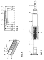
- FIG. 2 As essential elements of the front propeller shaft 5, an inner shaft member 5i with an inner toothing 6i and an outer shaft member 5a with an outer toothing 6a.
- the toothing sections 6i and 6a together form the in FIG. 3 apparent sliding toothing 6.
- the tubular shaft element 5a has a taper 7 for connection to a joint or a flexible disc.
- the inner - preferably embodied here as a hollow tube - wave element 5i has at its end facing away from the sliding toothing 6 a connecting flange 8 for connection to a joint or a flexible disc.
- the execution of the sliding toothing 6, of the in FIG. 4 a plan view of the toothing 6a can be seen.
- toothed outlets 9 and 10 which can be manufactured particularly easily and, in particular in the area of the toothed outlet 9, facilitate the assembly of the internal shaft element 5i to be inserted.
- Below the Veriereungsauslaufs 9 results together with a non-toothed portion 11 of the inner shaft member 5i, an annular gap 12, the at least partially filled with a sealant 13 at least in the region of a free end 5e of the outer shaft member 5a.
- the toothing 6i runs on - not quantified - free end of the inner shaft member 5i open and is particularly easy to produce, for example by cold forming such as cold rolling.
- the sketch in FIG. 6 clarifies the way in which after lifting the Axialfix ist the low-friction telescoping of the shaft elements 5a and 5i is possible.
- the outer diameter DIA of the gear-free portion 11 is smaller than the root diameter DAF on the outer shaft member 5a.
- the diameter DAI within the outer shaft member 5a is larger than the tip circle diameter DIK on the inner shaft member 5i and the root diameter DAF on the outer shaft member is larger than the root diameter DIF on the inner shaft member 5i.
- FIG. 7 Beads 14 and 15, which have been produced here in the manner of a longitudinal bead, for example by caulking, extruding, rolling or pressing or the like. Through these longitudinal beads 14, 15 in the inner shaft member 5i there are indentations and consequent undercuts 16, 17 in the outer shaft member 5a, so that on this form and frictional chosen combination of an axial fixation is achieved. In kinematic reversal such beads can also be impressed from the outside into the outer shaft member 5a, so that there is a comparable holding effect.
- FIG. 7 indicated almost existing backlash between the tooth flanks 18, 19 on the one hand and 20, 21 on the other.
- curable plastics bonds or welds 25 (see FIG Fig. 7a ) and / or shear pins 24 (see Fig. 7b ) be provided.
- bonds or welds 25 see FIG Fig. 7a
- shear pins 24 see Fig. 7b
- an insert part 27 which is fastened here to the shaft element 5 a and acts on the inner shaft element 5 i via a clamping body 28 and a sealing element 29.
- a kinematic reversal can be considered in terms of the determination of the insert and the functions seal and clamping.
- additional undercuts or grooves may also be provided in the shaft elements 5a, 5i in order to ensure defined axial fixings and sealing conditions.
- the beads 14, 14 ', 15 can be selected in terms of their length, width and height / depth or cross-sectional shape, that on the one hand, a defined limit force can be adjusted and on the other hand over the displacement of the sliding teeth 6 away a very specific identifier can be specified , According to the invention, this identifier of the displacement force over the displacement path has a predominantly falling course, so that no negative repercussions on the occupants accommodated in the vehicle 1 are to be expected on the part of the front propeller shaft 5.
- the beads can also be arranged distributed as Querwülste on the circumference to set a specific identifier.
- a design as longitudinal ridge, a continuous course (see FIG. 8 ) or a segment-like arrangement of a plurality of beads may be provided one behind the other.
- At least one of the beads is a clamping bead for providing the Axialfixmaschine and other beads are designed to specify a particular identifier on the displacement path.
- These beads may be associated with the inner and / or outer shaft member 5i and 5a, respectively.
- the use of the shaft assembly according to the invention is not on in the FIG. 1 limited vehicle concept, but can also for other drive configurations - for example, with a continuous propshaft - are selected.
Landscapes
- Engineering & Computer Science (AREA)
- General Engineering & Computer Science (AREA)
- Mechanical Engineering (AREA)
- Ocean & Marine Engineering (AREA)
- Shafts, Cranks, Connecting Bars, And Related Bearings (AREA)
- Surface Acoustic Wave Elements And Circuit Networks Thereof (AREA)
- Polishing Bodies And Polishing Tools (AREA)
Description
- Die Erfindung betrifft eine Wellenanordnung gemäß dem Oberbegriff des Patentanspruchs 1.
- Gattungsgemäße Wellenanordnungen werden beispielsweise beschrieben in den Dokumenten
US 6,279,221 undUS 6,193,612 . In diesem Zusammenhang wird auch auf eine Veröffentlichung hingewiesen, mit dem Titel "Slip-In-Tube-Gelenkwellen" Technologie (12. Aachener Kolloquium Fahrzeug- und Motorentechnik 2003, Seiten 1485 bis 1495). Eine Zielsetzung der dort beschriebenen Wellenanordnung besteht darin, dass im Crashfall das Kolabierverhalten optimiert werden soll. Vorgeschlagen wird hierzu, dass bei einer unfallbedingten Zusammenschiebung die Aufprallenergie zumindest teilweise durch gezielte Verformung absorbiert wird. Dazu wird beispielsweise ein inneres Wellenelement aus der Verzahnung heraus in einen Verjüngungsbereich eines äußeren Wellenelementes getrieben. Durch die Bewegung in den Verjüngungsbereich hinein wird dem inneren Wellenelement eine Verformung aufgezwungen, die letztlich zu Brüchen im Endbereich des inneren Wellenelementes führt. - Der Erfindung liegt die Aufgabe zugrunde, eine Wellenanordnung bereit zu stellen, durch die insbesondere für allradgetriebene Fahrzeuge bei Frontalaufprallunfällen eine Reduzierung der Insassenbelastung möglich ist.
- Diese Aufgabe wird gelöst mit einer Wellenanordnung gemäß den Merkmalen des Patentanspruchs 1. Die Unteransprüche betreffen besonders zweckmäßige Weiterbildungen dieser Erfindung.
- Abweichend von der bisherigen Auslegungsphilosophie mit gezielter Energieabsorption beim crashbedingten Kollabieren der teleskopierbaren Wellenelemente wird nun erfindungsgemäß vorgeschlagen, dass eine auf den Normalbetrieb des Fahrzeuges ausgelegte Axialfixierung vorgesehen wird, die bei einem Fahrzeugunfall nach Erreichen einer vorgegebenen Stoßkraft wirkungslos ist, also beispielsweise bricht, reißt, abschert oder dergleichen. Diese nach Art einer Sollbruchstelle ausgeführte Axialfixierung behindert nach ihrer Wirkungslosigkeit nicht mehr das Zusammenschieben der Wellenelemente ineinander, sondern erlaubt unter der Wirkung der Stoßkraft ein reibungsarmes Teleskopieren der Wellenelemente. Eine typische Größenordnung für die Auslegung der Axialfixierung kann ein Grenzkraftbetrag von beispielsweise 5 bis 40 KiloNewton sein. Erreicht bei einem Crash die Stoßkraft diesen vorgegebenen Grenzkraftbetrag, wird die Axialfixierung aufgehoben und der Stoßkraft damit ein geringerer Widerstand entgegengesetzt. Der Begriff reibungsarm ist hier so zu verstehen, dass auch Kraftbeträge von weniger als 50% bis 10 % des für die Axialfixierung ausgelegten Grenzkraftbetrages ausreichend sind, um die Wellenelemente relativ zueinander zu bewegen.
- Eine derartig ausgelegte Wellenanordnung, insbesondere für eine vordere Kardanwelle in einem allradgetriebenen Fahrzeug mit quer eingebautem Frontmotor, ist von Vorteil, weil durch jeglichen Verzicht auf Verformung in der Wellenanordnung keine Gefährdung durch ausknickende und wegbrechende Bauteile gegeben ist. Damit wird eine Intrusion solcher Bauteile in den Fahrgastraum sicher vermieden.
- Die Axialfixierung selbst kann bevorzugt auch dafür genutzt werden, dass gleichzeitig eine exakte Ausrichtung der Wellenachsen zueinander sichergestellt ist. In vorteilhafter Weise wird eine solche exakte Ausrichtung beispielsweise durch Pressungen zwischen Zahnkopf und Zahnfuß in der Verzahnung mindestens eines der beiden Wellenelemente erreicht.
- Zur Erhöhung der Lebensdauer erfindungsgemäßer Wellenanordnungen ist außerdem vorgesehen, dass in einem sich zwischen den Wellenelementen ergebenden Ringspalt eine Abdichtung eingebracht wird, die beispielsweise als Dichtring oder als ein gestaltloses Dichtmittel nach Art einer Paste oder eines Gels ausgeführt ist. Das Dichtmittel selbst kann auch durch einen Kleber realisiert sein, der damit zugleich auch die Funktion der Axialfixierung übernimmt. Ergänzend oder alternativ kann zur Axialfixierung auch ein zwischen beide Wellenelemente einpassbares Einsatzteil vorgesehen werden, dem bevorzugt auch ein Dichtelement zugeordnet ist.
- Für eine hohe Lebensdauer der gesamten Wellenanordnung wird bevorzugt die Verzahnung durch Kaltumformung, beispielsweise Kaltwalzen, eingebracht.
- Ein besonders vorteilhaftes Ausführungsbeispiel der Erfindung ist in der Zeichnung dargestellt. Es zeigt
- Figur 1:
- Eine typische Einbausituation für eine erfindungsgemäße Wellenanordnung in einem Fahrzeug,
- Figur 2:
- Am Beispiel einer Kardanwelle eine erfindungsgemäße Wellenanordnung vor dem Zusammenbau,
- Figur 3:
- Die Wellenanordnung gemäß
Figur 2 im zusammengebauten Zustand, - Figur 4:
- Eine Draufsicht auf einen in
Figur 3 mit Strichlinien markierten Abschnitt, - Figur 5:
- In einem Teilschnitt die Innenansicht für zwei zusammengebaute Wellenelemente,
- Figur 6:
- Einen Ausschnitt für einen in
Figur 5 mit durchgezogenen Linien markierten Abschnitt, - Figur 7:
- Eine erste Längswulst in einer der Verzahnungen sowie weitere Axialfixierungen in den
Figuren 7a und 7b , - Figur 8:
- Eine Ansicht gemäß Schnitt VIII-VIII in
Figur 7 , - Figur 9:
- Eine weitere Axialfixierung mittels Pressung zwischen Zahnkopf und Zahnfuß.
- Figur 10:
- Eine weitere Axialfixierung mittels eines Einsatzteils
-
Figur 1 zeigt schematisch ein insgesamt mit 1 bezeichnetes Fahrzeug, dessen wesentliche Elemente des Antriebsstranges hier ein Verbrennungsmotor 2, ein Getriebe 3, das Differential 4, eine vordere Kardanwelle 5, eine hintere Kardanwelle 22, ein hinteres Differential 23 sowie nicht weiter bezifferte Gelenkwellen und Räder sind. Der bevorzugte Anwendungsfall für die Erfindung ist hier die vordere Kardanwelle 5, deren Aufbau im Einzelnen nun näher erläutert wird. - So zeigt beispielsweise
Figur 2 als wesentliche Elemente der vorderen Kardanwelle 5 ein inneres Wellenelement 5i mit einer inneren Verzahnung 6i und ein äußeres Wellenelement 5a mit einer äußeren Verzahnung 6a. Die Verzahnungsabschnitte 6i und 6a bilden gemeinsam die inFigur 3 ersichtliche Schiebeverzahnung 6. Das rohrförmig ausgebildete Wellenelement 5a weist eine Verjüngung 7 zur Anbindung an ein Gelenk oder eine Gelenkscheibe auf. Das innere - bevorzugt hier auch als Hohlrohr ausgeführte - Wellenelement 5i weist an seinem der Schiebeverzahnung 6 abgewandten Ende einen Anschlussflansch 8 zur Anbindung an ein Gelenk oder eine Gelenkscheibe auf. Für die Erfindung wesentlich ist hier jedoch die Ausführung der Schiebeverzahnung 6, von der inFigur 4 eine Draufsicht auf die Verzahnung 6a erkennbar ist. - Wesentlich für den Verzahnungsabschnitt 6a sind Verzahnungsausläufe 9 und 10, die sich fertigungstechnisch besonders leicht herstellen lassen und insbesondere im Bereich des Verzahnungsauslaufes 9 auch die Montage für das einzuschiebende innere Wellenelement 5i erleichtert. Unterhalb des Verzahnungsauslaufs 9 ergibt sich zusammen mit einem hier verzahnungsfreien Abschnitt 11 des inneren Wellenelementes 5i ein Ringspalt 12, der zumindest im Bereich eines freien Endes 5e des äußeren Wellenelementes 5a zumindest teilweise mit einem Dichtmittel 13 ausgefüllt ist. Die Verzahnung 6i läuft am - nicht weiter bezifferten - freien Ende des inneren Wellenelementes 5i offen aus und ist so besonders leicht herstellbar, beispielsweise durch Kaltformung wie Kaltwalzen.
- Die Skizze in
Figur 6 verdeutlicht, auf welche Weise nach Aufhebung der Axialfixierung das reibungsarme Teleskopieren der Wellenelemente 5a und 5i möglich wird. So ist beispielsweise für das innere Wellenelement 5i der Außendurchmesser DIA des verzahnungsfreien Abschnittes 11 kleiner als der Fußkreisdurchmesser DAF am äußeren Wellenelement 5a. Korrespondierend ist der Durchmesser DAI innerhalb des äußeren Wellenelementes 5a größer als der Kopfkreisdurchmesser DIK am inneren Wellenelement 5i und der Fußkreisdurchmesser DAF am äußeren Wellenelement größer als der Fußkreisdurchmesser DIF am inneren Wellenelement 5i. Mit diesen Gestaltungsmerkmalen werden reibungsarme Relativbewegungen zwischen den Wellenelementen 5i und 5a ermöglicht, die hinsichtlich ihrer Ausdehnung durch eine als Axialanschlag wirksame Verjüngung 26 an dem äußeren Wellenelement 5a begrenzbar sind. Der Abstand dieser Verjüngung 26 ist so gewählt, dass auch bei maximalem Verschiebeweg der Schiebeverzahnung 6 dieser Anschlag nicht erreicht wird, sondern erst dann, wenn die Wellenanordnung ausgebaut würde. - Als Beispiel für eine Axialfixierung sind in
Figur 7 Wülste 14 und 15 gezeigt, die hier nach Art einer Längswulst beispielsweise durch Verstemmung, Fließpressen, Rollen oder Drücken oder dergleichen erzeugt worden sind. Durch diese Längswülste 14, 15 im inneren Wellenelement 5i kommt es zu Eindrückungen und daraus resultierenden Hinterschneidungen 16, 17 im äußeren Wellenelement 5a, so dass über diese aus Form- und Reibschluss gewählte Kombination einer Axialfixierung erreicht wird. In kinematischer Umkehr können derartige Wülste aber auch von außen in das äußere Wellenelement 5a eingeprägt werden, so dass sich eine vergleichbare Haltewirkung ergibt. Für die erfindungsgemäße Wellenanordnung von besonderer Bedeutung ist auch die inFigur 7 angedeutete nahezu vorhandene Spielfreiheit zwischen den Zahnflanken 18, 19 einerseits und 20, 21 andererseits. Hierdurch wird sichergestellt, dass die vordere Kardanwelle 5 nicht klappert (weil Verdrehspiel und Kippspiel minimiert sind) oder unnötig verschleißt und bei einem unfallbedingten Teleskopieren der Wellenelemente 5a, 5i eine definierte Führung gewährleistet ist. Bevorzugt für diese nahezu spielfreie Auslegung wird ein Verdrehspiel von 0 bis 0,5 mm zwischen den Zahnflanken 18,19 bzw. 20,21 für Wellendurchmesser zwischen 60 mm und 70 mm. - Ergänzend oder alternativ zu den Wülsten 14,15 können punktförmig oder großflächig auch aushärtbare Kunststoffe, Klebungen oder Schweißungen 25 (siehe
Fig. 7a ) und/oder Scherstifte 24 (sieheFig. 7b ) vorgesehen sein. Als Reibschlussvariante sind auch Längswülste 14' vorstellbar, die an dem Zahnfußbereich (sieheFig. 9 ) oder an den Zahnkopfbereich (hier nicht dargestellt) materialeinheitlich angeformt oder aufgetragen werden können. - Als weitere Ausführungsform für eine Axialfixierung zeigt
Figur 10 ein Einsatzteil 27, das hier an dem Wellenelement 5a befestigt und über einen Klemmkörper 28 und ein Dichtelement 29 das innere Wellenelement 5i beaufschlagt. Auch hier kann hinsichtlich der Festlegung des Einsatzteils und der Funktionen Dichtung und Klemmung eine kinematische Umkehr in Betracht gezogen werden. Je nach Auslegung können auch zusätzlich Hinterschneidungen oder Nuten in den Wellenelementen 5a, 5i vorgesehen sein, um definierte Axialfixierungen und Dichtverhältnisse sicherzustellen. - Die Wülste 14, 14', 15 können hinsichtlich ihrer Länge, Breite und Höhe/Tiefe oder Querschnittsgestalt so gewählt werden, dass zum einen eine definierte Grenzkraft eingestellt werden kann und zum anderen auch über dem Verschiebeweg der Schiebeverzahnung 6 hinweg eine ganz bestimmte Kennung vorgebbar ist. Erfindungsgemäß weist diese Kennung der Verschiebekraft über dem Verschiebeweg einen überwiegend fallenden Verlauf auf, so dass seitens der vorderen Kardanwelle 5 keinerlei negativen Rückwirkungen auf die in dem Fahrzeug 1 untergebrachten Insassen zu erwarten sind. Unterschieden werden können eine erste Phase, in der nach der Aufhebung der Axialfixierung die Schiebeverzahnung 6 noch in Eingriff ist und sich dementsprechend vorgegebene Kraft-Weg-Verläufe einstellen, und eine zweite Phase, in der die Verzahnungen 6i und 6a nicht mehr in Eingriff sind, so dass die Wellenelemente 5i,5a nahezu ungedämpft aneinander vorbei gleiten. Beide Phasen sind erfindungsgemäß reibungsarm ausgelegt. Zumindest die erste Phase weist den fallenden Kraft-Weg-Verlauf auf. In der zweiten Phase kann der Verlauf ggf. auch konstant oder auf geringem Niveau leicht ansteigend sein, ohne dabei aber das Kraft-Niveau der ersten Phase wieder zu erreichen.
- Die Wülste können zur Einstellung einer bestimmten Kennung auch als Querwülste auf dem Umfang verteilt angeordnet werden. Bei einer Ausführung als Längswulst kann ein kontinuierlicher Verlauf (siehe
Figur 8 ) oder eine segmentartige Anordnung mehrerer Wülste hintereinander vorgesehen sein. - Bei einer Anordnung mehrer Wülste kann auch vorgesehen sein, dass zumindest eine der Wülste eine Klemmwulst zur Bereitstellung der Axialfixierung ist und andere Wülste zur Vorgabe einer bestimmten Kennung über dem Verschiebeweg ausgelegt sind. Diese Wülste können dem inneren und/oder äußeren Wellenelement 5i bzw. 5a zugeordnet sein.
- Zur Einstellung der Kennung kann neben der Form der Längswülste auch deren radiale Verteilung auf dem Umfang der Wellenelemente 5i und/oder 5a variiert werden.
- Der Einsatz der erfindungsgemäßen Wellenanordnung ist nicht auf das in der
Figur 1 ersichtliche Fahrzeugkonzept beschränkt, sondern kann auch für andere Antriebskonfigurationen - beispielsweise mit einer durchgehenden Kardanwelle - gewählt werden.
Claims (12)
- Teleskopierbare Wellenanordnung mit wenigstens zwei ineinander verschiebbaren Wellenelementen, die als inneres Wellenelement (5i) einerseits und als äußeres Wellenelement (5a) andererseits über wenigstens eine Schiebeverzahnung (6) drehmomentenübertragend miteinander verbunden sind, wobei- nach Art einer Sollbruchstelle eine Axialfixierung (14, 14', 15) zwischen den Wellenelementen (5i, 5a) vorgesehen ist, die bei Erreichen einer in Teleskopierrichtung wirkenden, vorgegebenen Stoßkraft wirkungslos ist,- nach Wirkungslosigkeit der Axialfixierung die Wellenelemente (5i,5a) entlang der Schiebeverzahnung (6) unter Wirkung der Stoßkraft reibungsarm gegeneinander bewegbar sind,dadurch gekennzeichnet, dass
in der Schiebeverzahnung (6) wenigstens eine Wulst (14; 14', 15), vorgesehen ist, durch die für die verschiebende Stoßkraft über den Verschiebeweg hinweg ein vorgegebener Kraft-Weg-Verlauf nach dem Lösen der Axialfixierung einstellbar ist. - Wellenanordnung nach Anspruch 1, dadurch gekennzeichnet, dass die Dimensionierung der wenigstens einen Wulst (14, 14', 15) so gewählt ist, dass die Verschiebekraft über den Verschiebeweg einen fallenden Verlauf aufweist.
- Wellenanordnung nach Anspruch 1 oder 2, dadurch gekennzeichnet, dass die Axialfixierung durch eine Klebung (25) und/oder Schweißung (25) und/oder Verstemmung und/oder Abscher-Elementen-Kombination (24) und/oder Reibabschnitte (14') in der Schiebeverzahnung (6) und/oder dergleichen gebildet ist.
- Wellenanordnung nach wenigstens einem der vorhergehenden Ansprüche, dadurch gekennzeichnet, dass das äußere Wellenelement (5a) auf seiner dem inneren Wellenelement (5i) abgewandten Seite eine Verjüngung (26) aufweist, durch die eine stoßkraftbedingte Verlagerung des inneren Wellenelementes(5i) innerhalb des äußeren Wellenelementes (5a) nach Art eines Anschlages begrenzbar ist.
- Wellenanordnung nach wenigstens einem der vorhergehenden Ansprüche, dadurch gekennzeichnet, dass das innere Wellenelement (5i) auf seiner dem äußeren Wellenelement (5a) abgewandten Seite einen verzahnungsfreien Abschnitt (11) aufweist, dessen Außendurchmesser (DIA) zur ungehinderten Bewegung des äußeren Wellenelementes (5a) über das innere Wellenelement (5i) hinweg kleiner ist als der Fußkreisdurchmesser (DAF) der Verzahnung (6a) des äußeren Wellenelementes (5a).
- Wellenanordnung nach wenigstens einem der vorhergehenden Ansprüche, dadurch gekennzeichnet, dass die Verzahnungsabschnitte (6i, 6a) der Wellenelemente (5i, 5a) zur Drehmomentenübertragung nahezu spielfrei zueinander angeordnet sind.
- Wellenanordnung nach wenigstens einem der vorhergehenden Ansprüche, dadurch gekennzeichnet, dass bei dem inneren Wellenelement (5i) der Durchmesser (DIF) des Fußkreises der Verzahnung (6i) größer ist als der Außendurchmesser (DIA) des sich an die Verzahnung (6i) anschließenden verzahnungsfreien Abschnittes (11) des inneren Wellenelementes (5i).
- Wellenanordnung nach wenigstens einem der vorhergehenden Ansprüche, dadurch gekennzeichnet, dass die Verzahnung (6i) des inneren Wellenelementes (5i) an dessen dem äußeren Wellenelement (5a) zugewandtem Ende offen auslaufend ist.
- Wellenanordnung nach wenigstens einem der vorhergehenden Ansprüche, dadurch gekennzeichnet, dass bei dem äußeren Wellenelement (5a) der Innendurchmesser (DAI) des verzahnungsfreien Abschnittes größer ist als der Kopfkreisdurchmesser (DIK) an der Verzahnung (6i) des inneren Wellenelementes (5i).
- Wellenanordnung nach wenigstens einem der vorhergehenden Ansprüche, dadurch gekennzeichnet, dass bei wirksamer Axialfixierung zwischen einem Verzahnungsauslauf (9) an einem freien Ende (5e) des äußeren Wellenelementes (5a) und einem verzahnungsfreien Abschnitt (11) des inneren Wellenelementes (5i) ein Ringspalt (12) gebildet ist, der zumindest im Bereich des freien Endes (5e) des äußeren Wellenelementes (5a) zumindest teilweise mit einem Dichtmittel (13) ausgefüllt ist.
- Wellenanordnung nach Anspruch 10, dadurch gekennzeichnet, dass der Ringspalt (12) durch das Dichtmittel (13) abgedichtet ist.
- Wellenanordnung nach Anspruch 10 oder 11, dadurch gekennzeichnet, dass das Dichtmittel (13) ein Dichtring oder ein gestaltloses Dichtmittel nach Art einer Dichtschnur, einer Paste oder eines Gels ist.
Priority Applications (1)
| Application Number | Priority Date | Filing Date | Title |
|---|---|---|---|
| SI200530702T SI1792090T1 (sl) | 2004-09-07 | 2005-08-19 | Razporeditev gredi |
Applications Claiming Priority (2)
| Application Number | Priority Date | Filing Date | Title |
|---|---|---|---|
| DE102004043621A DE102004043621A1 (de) | 2004-09-07 | 2004-09-07 | Wellenanordnung |
| PCT/EP2005/008975 WO2006027094A1 (de) | 2004-09-07 | 2005-08-19 | Wellenanordnung |
Publications (2)
| Publication Number | Publication Date |
|---|---|
| EP1792090A1 EP1792090A1 (de) | 2007-06-06 |
| EP1792090B1 true EP1792090B1 (de) | 2009-04-08 |
Family
ID=35447734
Family Applications (1)
| Application Number | Title | Priority Date | Filing Date |
|---|---|---|---|
| EP05781768A Expired - Lifetime EP1792090B1 (de) | 2004-09-07 | 2005-08-19 | Wellenanordnung |
Country Status (6)
| Country | Link |
|---|---|
| US (2) | US20070178975A1 (de) |
| EP (1) | EP1792090B1 (de) |
| AT (1) | ATE428061T1 (de) |
| DE (2) | DE102004043621A1 (de) |
| SI (1) | SI1792090T1 (de) |
| WO (1) | WO2006027094A1 (de) |
Families Citing this family (27)
| Publication number | Priority date | Publication date | Assignee | Title |
|---|---|---|---|---|
| DE102004043621A1 (de) | 2004-09-07 | 2006-03-23 | Volkswagen Ag | Wellenanordnung |
| DE102006043044A1 (de) * | 2006-09-14 | 2008-03-27 | Zf Friedrichshafen Ag | Verbindungswelle in einem Allradfahrzeug-Antriebsstrang |
| DE102007012195B4 (de) | 2007-03-14 | 2012-04-26 | Dr. Ing. H.C. F. Porsche Aktiengesellschaft | Verbindungswelle in einem Allradfahrzeug-Antriebsstrang |
| FR2917474B1 (fr) * | 2007-06-18 | 2009-08-07 | Skf Aerospace France Soc Par A | Arbre de transmission de mouvements et/ou d'efforts en rotation |
| DE102009020037A1 (de) | 2008-05-22 | 2009-11-26 | Ifa-Technologies Gmbh | Teleskopierbare Antriebswelle |
| DE102008034774A1 (de) | 2008-07-25 | 2010-01-28 | Bayerische Motoren Werke Aktiengesellschaft | Wellenanordnung mit ineinander verschiebbaren inneren und äußeren Wellenelementen |
| US7922593B2 (en) * | 2008-10-23 | 2011-04-12 | American Axle & Manufacturing, Inc. | Driveshaft assembly |
| US8800754B2 (en) | 2009-09-22 | 2014-08-12 | OCS Intellitrak, Inc. | Conveyor system with interchangeable drive tube couplings |
| US20110070020A1 (en) * | 2009-09-22 | 2011-03-24 | Tabler Charles P | Heavy-Duty Drive Tube Coupling |
| WO2012006335A1 (en) * | 2010-07-06 | 2012-01-12 | Szuba Consulting, Inc. | Collapsible shaft assembly |
| JP5609378B2 (ja) * | 2010-07-27 | 2014-10-22 | 株式会社ジェイテクト | プロペラシャフト |
| DE102013009497A1 (de) * | 2013-06-05 | 2014-12-11 | Daimler Ag | Teleskopierbare Antriebswelle |
| AT515177B1 (de) * | 2013-12-10 | 2015-08-15 | Asmag Holding Gmbh | Antriebssystem sowie damit ausgerüstete Profilieranlage |
| US10072712B2 (en) * | 2015-06-18 | 2018-09-11 | GM Global Technology Operations LLC | Shaft coupling arrangement |
| US20170058940A1 (en) * | 2015-08-26 | 2017-03-02 | Neapco Drivelines, Llc | Radial pilot for slip-in-tube driveshaft |
| DE102015014503A1 (de) | 2015-11-10 | 2017-05-11 | HMP Heinrich Müller Maschinenfabrik GmbH | Zusammenschiebbares Hohlrohr zur Drehmomentübertragung in einer Kardanwelle und Verfahren zu dessen Herstellung |
| DE102016206619A1 (de) * | 2016-04-19 | 2017-10-19 | Bayerische Motoren Werke Aktiengesellschaft | Gelenkwelle für ein Kraftfahrzeug |
| US9845861B1 (en) * | 2016-05-26 | 2017-12-19 | GM Global Technology Operations LLC | Rotatable assembly including a coupling interface |
| WO2018064192A1 (en) * | 2016-09-27 | 2018-04-05 | Neapco Intellectual Property Holdings, Llc | Solar panel drive shaft |
| EP3396182A1 (de) * | 2017-04-24 | 2018-10-31 | Bochumer Eisenhütte Heintzmann GmbH&Co. Kg | Axiales widerstandsgleitlager |
| EP3615822B1 (de) * | 2017-04-25 | 2021-06-02 | GKN Driveline Deutschland GmbH | Wellenverbindung und antriebswelle mit einer solchen wellenverbindung |
| US11052937B2 (en) * | 2018-01-19 | 2021-07-06 | Steering Solutions Ip Holding Corporation | Splined component assembly and method |
| WO2019195370A1 (en) | 2018-04-03 | 2019-10-10 | Composite Drivelines, LLC | Composite vehicle driveshaft with welded joint system |
| WO2019195306A1 (en) | 2018-04-03 | 2019-10-10 | Composite Drivelines, LLC | Composite vehicle driveshaft with crash collapse system |
| CN109458445B (zh) * | 2018-12-26 | 2024-06-14 | 江苏沃得高新农业装备有限公司 | 轴连带传动装置 |
| US11761489B2 (en) * | 2019-06-14 | 2023-09-19 | Gkn Driveline Deutschland Gmbh | Gear-tooth system and shaft/hub connection component |
| WO2021076598A1 (en) | 2019-10-15 | 2021-04-22 | Composite Drivelines, LLC | Composite vehicle driveshaft assembly with bonded end yoke and method of producing same |
Family Cites Families (14)
| Publication number | Priority date | Publication date | Assignee | Title |
|---|---|---|---|---|
| US2895345A (en) * | 1956-11-13 | 1959-07-21 | Gen Motors Corp | Safety steering wheel |
| US3016722A (en) * | 1959-05-26 | 1962-01-16 | Ford Motor Co | Slip joint seal |
| US3197216A (en) * | 1962-07-31 | 1965-07-27 | Homer E Jackson | Alignment control and seal for spline drives |
| US3290918A (en) * | 1963-12-06 | 1966-12-13 | Anthony V Weasler | Method of manufacturing a shaft coupling |
| US4915536A (en) * | 1987-09-29 | 1990-04-10 | Dana Corporation | Modular yoke end |
| DE4119359C2 (de) * | 1990-06-23 | 1997-03-13 | Gkn Glaenzer Spicer | Antriebswelle |
| DE19504036C1 (de) | 1995-02-08 | 1996-06-27 | Lemfoerder Metallwaren Ag | Sicherheitslenkwelle |
| ES2129322B1 (es) | 1996-04-18 | 2000-02-01 | Castellon Melchor Daumal | Perfeccionamientos en los arboles telescopicos. |
| JP3323400B2 (ja) * | 1996-07-19 | 2002-09-09 | 株式会社山田製作所 | ステアリングの中間シャフト装置 |
| JP3670437B2 (ja) * | 1997-03-18 | 2005-07-13 | 株式会社日立製作所 | 衝撃吸収可能な動力伝達装置 |
| US6193612B1 (en) * | 1998-08-10 | 2001-02-27 | Ford Global Technologies, Inc. | Collapsible driveshaft |
| DE69922335T2 (de) * | 1999-02-23 | 2005-12-15 | Matsui Universal Joint Corp. | Antriebswelle und Verfahren zur Herstellung derselben |
| US6279221B1 (en) * | 1999-09-08 | 2001-08-28 | Visteon Global Tech., Inc. | Vehicle driveshaft |
| DE102004043621A1 (de) | 2004-09-07 | 2006-03-23 | Volkswagen Ag | Wellenanordnung |
-
2004
- 2004-09-07 DE DE102004043621A patent/DE102004043621A1/de not_active Withdrawn
-
2005
- 2005-08-19 SI SI200530702T patent/SI1792090T1/sl unknown
- 2005-08-19 WO PCT/EP2005/008975 patent/WO2006027094A1/de not_active Ceased
- 2005-08-19 AT AT05781768T patent/ATE428061T1/de not_active IP Right Cessation
- 2005-08-19 EP EP05781768A patent/EP1792090B1/de not_active Expired - Lifetime
- 2005-08-19 DE DE502005007049T patent/DE502005007049D1/de not_active Expired - Lifetime
-
2007
- 2007-03-07 US US11/715,254 patent/US20070178975A1/en not_active Abandoned
-
2009
- 2009-11-25 US US12/625,745 patent/US7946924B2/en not_active Expired - Fee Related
Also Published As
| Publication number | Publication date |
|---|---|
| DE502005007049D1 (de) | 2009-05-20 |
| US7946924B2 (en) | 2011-05-24 |
| DE102004043621A1 (de) | 2006-03-23 |
| ATE428061T1 (de) | 2009-04-15 |
| EP1792090A1 (de) | 2007-06-06 |
| SI1792090T1 (sl) | 2009-08-31 |
| US20100075766A1 (en) | 2010-03-25 |
| WO2006027094A1 (de) | 2006-03-16 |
| US20070178975A1 (en) | 2007-08-02 |
Similar Documents
| Publication | Publication Date | Title |
|---|---|---|
| EP1792090A1 (de) | Wellenanordnung | |
| DE4119359C2 (de) | Antriebswelle | |
| EP3297889B1 (de) | Lenksäule für ein kraftfahrzeug und energieabsorptionseinrichtung | |
| DE3822637C2 (de) | ||
| DE102017207561A1 (de) | Lenksäule für ein Kraftfahrzeug und Verfahren zur Herstellung einer Lenksäule | |
| EP2505424A1 (de) | Spindelantrieb für eine Sitzlängsverstellung eines Kraftfahrzeugsitzes | |
| CH652807A5 (de) | Anschlussverbindung zwischen einer durch ein faserkunststoffrohr gebildeten hohlwelle und einem anschlusselement. | |
| DE102006062822B4 (de) | Antriebswelle und Gleichlaufgelenk hierfür | |
| DE102016205378B3 (de) | Lenksäule für ein Kraftfahrzeug | |
| DE19752887A1 (de) | Universalgelenkwelle eines Lenksystems zum Absorbieren und Abfangen von Stoßenergie bei einem Zusammenstoß | |
| WO2008031738A1 (de) | Verbindungswelle in einem allradfahrzeug-antriebsstrang | |
| WO2007036343A1 (de) | Gelenkwelle und rollverschiebeeinheit hierfür | |
| DE112004000239T5 (de) | Verbesserte Längsantriebswelle mit mehrfachen Crash-Schutzmechanismen | |
| EP2102518B1 (de) | Längsantriebswelle für kraftfahrzeuge | |
| EP3927983B1 (de) | Lenksäule für ein kraftfahrzeug | |
| DE102016113687A1 (de) | Innenverzahntes Hohlrad für ein Spannungswellengetriebe | |
| DE3920793C2 (de) | Verbindungsanordnung | |
| EP1294594B1 (de) | Überlastsicherung und ein verfahren zu deren herstellung | |
| EP1692002B1 (de) | Teleskopierbares antriebsgelenk | |
| EP3615822B1 (de) | Wellenverbindung und antriebswelle mit einer solchen wellenverbindung | |
| EP1646546B1 (de) | Deformationsanordnung für lenkstrang | |
| DE19515180C2 (de) | Gebaute Welle zur Kraftübertragung | |
| DE102006006980B4 (de) | Antriebswelle und Gleichlaufgelenk hierfür | |
| DE102005029754A1 (de) | Mehrteilige Längsantriebswelle mit Schutzelement | |
| DE10349514B3 (de) | Axial ineinanderschiebbare Kraftfahrzeug-Antriebswelle |
Legal Events
| Date | Code | Title | Description |
|---|---|---|---|
| PUAI | Public reference made under article 153(3) epc to a published international application that has entered the european phase |
Free format text: ORIGINAL CODE: 0009012 |
|
| 17P | Request for examination filed |
Effective date: 20070410 |
|
| AK | Designated contracting states |
Kind code of ref document: A1 Designated state(s): AT BE BG CH CY CZ DE DK EE ES FI FR GB GR HU IE IS IT LI LT LU LV MC NL PL PT RO SE SI SK TR |
|
| DAX | Request for extension of the european patent (deleted) | ||
| 17Q | First examination report despatched |
Effective date: 20080311 |
|
| GRAP | Despatch of communication of intention to grant a patent |
Free format text: ORIGINAL CODE: EPIDOSNIGR1 |
|
| GRAP | Despatch of communication of intention to grant a patent |
Free format text: ORIGINAL CODE: EPIDOSNIGR1 |
|
| GRAS | Grant fee paid |
Free format text: ORIGINAL CODE: EPIDOSNIGR3 |
|
| GRAA | (expected) grant |
Free format text: ORIGINAL CODE: 0009210 |
|
| AK | Designated contracting states |
Kind code of ref document: B1 Designated state(s): AT BE BG CH CY CZ DE DK EE ES FI FR GB GR HU IE IS IT LI LT LU LV MC NL PL PT RO SE SI SK TR |
|
| REG | Reference to a national code |
Ref country code: GB Ref legal event code: FG4D Free format text: NOT ENGLISH |
|
| REG | Reference to a national code |
Ref country code: CH Ref legal event code: EP |
|
| REG | Reference to a national code |
Ref country code: IE Ref legal event code: FG4D |
|
| REF | Corresponds to: |
Ref document number: 502005007049 Country of ref document: DE Date of ref document: 20090520 Kind code of ref document: P |
|
| NLV1 | Nl: lapsed or annulled due to failure to fulfill the requirements of art. 29p and 29m of the patents act | ||
| REG | Reference to a national code |
Ref country code: IE Ref legal event code: FD4D |
|
| PG25 | Lapsed in a contracting state [announced via postgrant information from national office to epo] |
Ref country code: PT Free format text: LAPSE BECAUSE OF FAILURE TO SUBMIT A TRANSLATION OF THE DESCRIPTION OR TO PAY THE FEE WITHIN THE PRESCRIBED TIME-LIMIT Effective date: 20090908 Ref country code: LT Free format text: LAPSE BECAUSE OF FAILURE TO SUBMIT A TRANSLATION OF THE DESCRIPTION OR TO PAY THE FEE WITHIN THE PRESCRIBED TIME-LIMIT Effective date: 20090408 Ref country code: FI Free format text: LAPSE BECAUSE OF FAILURE TO SUBMIT A TRANSLATION OF THE DESCRIPTION OR TO PAY THE FEE WITHIN THE PRESCRIBED TIME-LIMIT Effective date: 20090408 Ref country code: ES Free format text: LAPSE BECAUSE OF FAILURE TO SUBMIT A TRANSLATION OF THE DESCRIPTION OR TO PAY THE FEE WITHIN THE PRESCRIBED TIME-LIMIT Effective date: 20090719 |
|
| PG25 | Lapsed in a contracting state [announced via postgrant information from national office to epo] |
Ref country code: SE Free format text: LAPSE BECAUSE OF FAILURE TO SUBMIT A TRANSLATION OF THE DESCRIPTION OR TO PAY THE FEE WITHIN THE PRESCRIBED TIME-LIMIT Effective date: 20090708 Ref country code: PL Free format text: LAPSE BECAUSE OF FAILURE TO SUBMIT A TRANSLATION OF THE DESCRIPTION OR TO PAY THE FEE WITHIN THE PRESCRIBED TIME-LIMIT Effective date: 20090408 Ref country code: NL Free format text: LAPSE BECAUSE OF FAILURE TO SUBMIT A TRANSLATION OF THE DESCRIPTION OR TO PAY THE FEE WITHIN THE PRESCRIBED TIME-LIMIT Effective date: 20090408 Ref country code: LV Free format text: LAPSE BECAUSE OF FAILURE TO SUBMIT A TRANSLATION OF THE DESCRIPTION OR TO PAY THE FEE WITHIN THE PRESCRIBED TIME-LIMIT Effective date: 20090408 Ref country code: IS Free format text: LAPSE BECAUSE OF FAILURE TO SUBMIT A TRANSLATION OF THE DESCRIPTION OR TO PAY THE FEE WITHIN THE PRESCRIBED TIME-LIMIT Effective date: 20090808 |
|
| PG25 | Lapsed in a contracting state [announced via postgrant information from national office to epo] |
Ref country code: IE Free format text: LAPSE BECAUSE OF FAILURE TO SUBMIT A TRANSLATION OF THE DESCRIPTION OR TO PAY THE FEE WITHIN THE PRESCRIBED TIME-LIMIT Effective date: 20090408 Ref country code: RO Free format text: LAPSE BECAUSE OF FAILURE TO SUBMIT A TRANSLATION OF THE DESCRIPTION OR TO PAY THE FEE WITHIN THE PRESCRIBED TIME-LIMIT Effective date: 20090408 Ref country code: CZ Free format text: LAPSE BECAUSE OF FAILURE TO SUBMIT A TRANSLATION OF THE DESCRIPTION OR TO PAY THE FEE WITHIN THE PRESCRIBED TIME-LIMIT Effective date: 20090408 Ref country code: DK Free format text: LAPSE BECAUSE OF FAILURE TO SUBMIT A TRANSLATION OF THE DESCRIPTION OR TO PAY THE FEE WITHIN THE PRESCRIBED TIME-LIMIT Effective date: 20090408 Ref country code: EE Free format text: LAPSE BECAUSE OF FAILURE TO SUBMIT A TRANSLATION OF THE DESCRIPTION OR TO PAY THE FEE WITHIN THE PRESCRIBED TIME-LIMIT Effective date: 20090408 |
|
| PLBE | No opposition filed within time limit |
Free format text: ORIGINAL CODE: 0009261 |
|
| STAA | Information on the status of an ep patent application or granted ep patent |
Free format text: STATUS: NO OPPOSITION FILED WITHIN TIME LIMIT |
|
| PG25 | Lapsed in a contracting state [announced via postgrant information from national office to epo] |
Ref country code: SK Free format text: LAPSE BECAUSE OF FAILURE TO SUBMIT A TRANSLATION OF THE DESCRIPTION OR TO PAY THE FEE WITHIN THE PRESCRIBED TIME-LIMIT Effective date: 20090408 |
|
| BERE | Be: lapsed |
Owner name: VOLKSWAGEN A.G. Effective date: 20090831 |
|
| 26N | No opposition filed |
Effective date: 20100111 |
|
| PG25 | Lapsed in a contracting state [announced via postgrant information from national office to epo] |
Ref country code: MC Free format text: LAPSE BECAUSE OF NON-PAYMENT OF DUE FEES Effective date: 20090831 Ref country code: BG Free format text: LAPSE BECAUSE OF FAILURE TO SUBMIT A TRANSLATION OF THE DESCRIPTION OR TO PAY THE FEE WITHIN THE PRESCRIBED TIME-LIMIT Effective date: 20090708 |
|
| REG | Reference to a national code |
Ref country code: CH Ref legal event code: PL |
|
| PG25 | Lapsed in a contracting state [announced via postgrant information from national office to epo] |
Ref country code: CH Free format text: LAPSE BECAUSE OF NON-PAYMENT OF DUE FEES Effective date: 20090831 Ref country code: LI Free format text: LAPSE BECAUSE OF NON-PAYMENT OF DUE FEES Effective date: 20090831 |
|
| PG25 | Lapsed in a contracting state [announced via postgrant information from national office to epo] |
Ref country code: BE Free format text: LAPSE BECAUSE OF NON-PAYMENT OF DUE FEES Effective date: 20090831 |
|
| PG25 | Lapsed in a contracting state [announced via postgrant information from national office to epo] |
Ref country code: GR Free format text: LAPSE BECAUSE OF FAILURE TO SUBMIT A TRANSLATION OF THE DESCRIPTION OR TO PAY THE FEE WITHIN THE PRESCRIBED TIME-LIMIT Effective date: 20090709 |
|
| PG25 | Lapsed in a contracting state [announced via postgrant information from national office to epo] |
Ref country code: AT Free format text: LAPSE BECAUSE OF NON-PAYMENT OF DUE FEES Effective date: 20090819 |
|
| PG25 | Lapsed in a contracting state [announced via postgrant information from national office to epo] |
Ref country code: LU Free format text: LAPSE BECAUSE OF NON-PAYMENT OF DUE FEES Effective date: 20090819 |
|
| PG25 | Lapsed in a contracting state [announced via postgrant information from national office to epo] |
Ref country code: HU Free format text: LAPSE BECAUSE OF FAILURE TO SUBMIT A TRANSLATION OF THE DESCRIPTION OR TO PAY THE FEE WITHIN THE PRESCRIBED TIME-LIMIT Effective date: 20091009 |
|
| PG25 | Lapsed in a contracting state [announced via postgrant information from national office to epo] |
Ref country code: TR Free format text: LAPSE BECAUSE OF FAILURE TO SUBMIT A TRANSLATION OF THE DESCRIPTION OR TO PAY THE FEE WITHIN THE PRESCRIBED TIME-LIMIT Effective date: 20090408 |
|
| PG25 | Lapsed in a contracting state [announced via postgrant information from national office to epo] |
Ref country code: CY Free format text: LAPSE BECAUSE OF FAILURE TO SUBMIT A TRANSLATION OF THE DESCRIPTION OR TO PAY THE FEE WITHIN THE PRESCRIBED TIME-LIMIT Effective date: 20090408 |
|
| PGFP | Annual fee paid to national office [announced via postgrant information from national office to epo] |
Ref country code: SI Payment date: 20110803 Year of fee payment: 7 |
|
| PGFP | Annual fee paid to national office [announced via postgrant information from national office to epo] |
Ref country code: IT Payment date: 20110822 Year of fee payment: 7 |
|
| REG | Reference to a national code |
Ref country code: SI Ref legal event code: KO00 Effective date: 20130326 |
|
| PG25 | Lapsed in a contracting state [announced via postgrant information from national office to epo] |
Ref country code: SI Free format text: LAPSE BECAUSE OF NON-PAYMENT OF DUE FEES Effective date: 20120820 Ref country code: IT Free format text: LAPSE BECAUSE OF NON-PAYMENT OF DUE FEES Effective date: 20120819 |
|
| REG | Reference to a national code |
Ref country code: FR Ref legal event code: PLFP Year of fee payment: 11 |
|
| REG | Reference to a national code |
Ref country code: FR Ref legal event code: PLFP Year of fee payment: 12 |
|
| REG | Reference to a national code |
Ref country code: FR Ref legal event code: PLFP Year of fee payment: 13 |
|
| REG | Reference to a national code |
Ref country code: FR Ref legal event code: PLFP Year of fee payment: 14 |
|
| PGFP | Annual fee paid to national office [announced via postgrant information from national office to epo] |
Ref country code: DE Payment date: 20190831 Year of fee payment: 15 |
|
| PGFP | Annual fee paid to national office [announced via postgrant information from national office to epo] |
Ref country code: GB Payment date: 20200825 Year of fee payment: 16 Ref country code: FR Payment date: 20200824 Year of fee payment: 16 |
|
| REG | Reference to a national code |
Ref country code: DE Ref legal event code: R119 Ref document number: 502005007049 Country of ref document: DE |
|
| PG25 | Lapsed in a contracting state [announced via postgrant information from national office to epo] |
Ref country code: DE Free format text: LAPSE BECAUSE OF NON-PAYMENT OF DUE FEES Effective date: 20210302 |
|
| GBPC | Gb: european patent ceased through non-payment of renewal fee |
Effective date: 20210819 |
|
| PG25 | Lapsed in a contracting state [announced via postgrant information from national office to epo] |
Ref country code: GB Free format text: LAPSE BECAUSE OF NON-PAYMENT OF DUE FEES Effective date: 20210819 Ref country code: FR Free format text: LAPSE BECAUSE OF NON-PAYMENT OF DUE FEES Effective date: 20210831 |