EP1786652B1 - Staudruckabh[ngige dachkofferverriegelung - Google Patents
Staudruckabh[ngige dachkofferverriegelung Download PDFInfo
- Publication number
- EP1786652B1 EP1786652B1 EP05779656A EP05779656A EP1786652B1 EP 1786652 B1 EP1786652 B1 EP 1786652B1 EP 05779656 A EP05779656 A EP 05779656A EP 05779656 A EP05779656 A EP 05779656A EP 1786652 B1 EP1786652 B1 EP 1786652B1
- Authority
- EP
- European Patent Office
- Prior art keywords
- safety device
- locking member
- locking
- box
- closing safety
- Prior art date
- Legal status (The legal status is an assumption and is not a legal conclusion. Google has not performed a legal analysis and makes no representation as to the accuracy of the status listed.)
- Expired - Lifetime
Links
Images


Classifications
-
- E—FIXED CONSTRUCTIONS
- E05—LOCKS; KEYS; WINDOW OR DOOR FITTINGS; SAFES
- E05B—LOCKS; ACCESSORIES THEREFOR; HANDCUFFS
- E05B65/00—Locks or fastenings for special use
- E05B65/52—Other locks for chests, boxes, trunks, baskets, travelling bags, or the like
- E05B65/5207—Other locks for chests, boxes, trunks, baskets, travelling bags, or the like characterised by bolt movement
- E05B65/5246—Other locks for chests, boxes, trunks, baskets, travelling bags, or the like characterised by bolt movement rotating
- E05B65/5269—Other locks for chests, boxes, trunks, baskets, travelling bags, or the like characterised by bolt movement rotating about an axis parallel to the surface on which the lock is mounted
- E05B65/5276—Other locks for chests, boxes, trunks, baskets, travelling bags, or the like characterised by bolt movement rotating about an axis parallel to the surface on which the lock is mounted parallel to the wing edge
-
- B—PERFORMING OPERATIONS; TRANSPORTING
- B60—VEHICLES IN GENERAL
- B60R—VEHICLES, VEHICLE FITTINGS, OR VEHICLE PARTS, NOT OTHERWISE PROVIDED FOR
- B60R9/00—Supplementary fittings on vehicle exterior for carrying loads, e.g. luggage, sports gear or the like
- B60R9/04—Carriers associated with vehicle roof
- B60R9/055—Enclosure-type carriers, e.g. containers, boxes
-
- E—FIXED CONSTRUCTIONS
- E05—LOCKS; KEYS; WINDOW OR DOOR FITTINGS; SAFES
- E05B—LOCKS; ACCESSORIES THEREFOR; HANDCUFFS
- E05B51/00—Operating or controlling locks or other fastening devices by other non-mechanical means
- E05B51/02—Operating or controlling locks or other fastening devices by other non-mechanical means by pneumatic or hydraulic means
- E05B51/023—Operating or controlling locks or other fastening devices by other non-mechanical means by pneumatic or hydraulic means actuated in response to external pressure, blast or explosion
-
- E—FIXED CONSTRUCTIONS
- E05—LOCKS; KEYS; WINDOW OR DOOR FITTINGS; SAFES
- E05B—LOCKS; ACCESSORIES THEREFOR; HANDCUFFS
- E05B63/00—Locks or fastenings with special structural characteristics
- E05B63/0004—Additional locks added to existing lock arrangements
-
- E—FIXED CONSTRUCTIONS
- E05—LOCKS; KEYS; WINDOW OR DOOR FITTINGS; SAFES
- E05B—LOCKS; ACCESSORIES THEREFOR; HANDCUFFS
- E05B65/00—Locks or fastenings for special use
- E05B65/52—Other locks for chests, boxes, trunks, baskets, travelling bags, or the like
- E05B65/5207—Other locks for chests, boxes, trunks, baskets, travelling bags, or the like characterised by bolt movement
- E05B65/5215—Other locks for chests, boxes, trunks, baskets, travelling bags, or the like characterised by bolt movement sliding
- E05B65/5223—Other locks for chests, boxes, trunks, baskets, travelling bags, or the like characterised by bolt movement sliding perpendicular to the surface on which the lock is mounted
Definitions
- the invention relates to a locking device for roof box to prevent unfolding of the edge of the case by excessive wind pressure or failure of the normal locking system while driving, in which engages a locking member on a suitcase part in a counterpart on the other case part.
- the invention is therefore the object of a locking device of the type mentioned in such a way that it is ineffective when the vehicle is stationary and is effective only when the vehicle is moving.
- the invention provides that the arranged on a suitcase part resiliently biased in a non-engaged position locking member is designed and arranged so that it is pivoted by the airstream only while driving in its locking position.
- the locking member can be connected to a dynamic pressure-dependent actuator of any kind, starting from the increasing back pressure with increasing speed of the vehicle, the locking member moved from the non-engaged position into the engaged position under additional light securing lock the case lid on the case base.
- the locking member arranged on a suitcase part is a locking hook or locking pin which engages over or overlaps an edge flange of the counter-luggage part or engages in a transverse recess of this counter-luggage part.
- the locking member could be arranged on each of the luggage parts, it has proven to be particularly useful in practice, when the locking member is arranged on the roof box upper part.
- a particularly simple and reliable execution of a locking device according to the invention results in an embodiment of the invention in that the locking member is arranged on an acted upon by the wind and adjustable in the locking position Druckverstellplatte, which in turn is resiliently mounted on a mountable on a suitcase foot part.
- a first embodiment of the present invention can this Druckverstellplatte formed as a wing plate pivotally mounted preferably formed as a foot plate foot, wherein the pivot axis both horizontally, that is parallel to Koffertrnenbene, as well as vertically, that can be arranged perpendicular to Koffertrnenbene.
- the pivot axis both horizontally, that is parallel to Koffertrnenbene, as well as vertically, that can be arranged perpendicular to Koffertrnenbene.
- the Druckverstellplatte forms the piston of a dynamic pressure cylinder, which is arranged for example at the front edge of the roof box, wherein the piston rod of this dynamic pressure cylinder either carries the locking member or this locking member forms directly.
- the Druckverstellplatte is a locking member supporting resilient membrane.
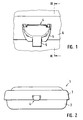
- an additional locking device according to the invention is indicated, which prevents a caused by the airstream swiveling the lid 3 at the front end of the case relative to the lower part 2 while driving.
- the locking device 4 is designed so that it is retired, ie when the vehicle is stationary ( Fig. 1 and 3 pulled drawn) is arranged in a biased by a spring non-locking position and only by the driving pressure in the locking position ( Fig. 2 . 3 dashed lines and Fig. 4 ) is pivoted.
- the locking device 4 after the Fig. 1-5 comprises a base plate 5 which is fixed to the edge 6 of the lid 3, and a pressure adjusting plate pivotally mounted on this base plate 5 via a pivot bearing 7 with a return spring 8, which here is designed as a wing plate 9, and which carries a locking hook 10.
- This locking hook 10 is in the rest position, that is, when the vehicle is in the in Fig. 3 pulled outwardly pivoted position shown and arranged by the return spring in this position held so that the lid 3 can be opened easily.
- the lock fuse 4 is therefore not effective when the vehicle is stationary.
- the 6 and 7 show a second embodiment in which the lock fuse 4 'designed as a dynamic pressure piston foot part 5' and a against a spring assembly 8 'by acting in the direction of an axis 12 wind pressure displaceable, a Druckverstellplatte forming piston 9'.
- Its piston rod 10 forms in this case directly a locking pin, the lower the bottom of the dynamic pressure cylinder, from the in Fig. 7 shown rest position at the front tip of the roof box can be pressed by the wind acting in the direction of arrow 13 in a locking recess 14 of the sealing edge 11 of the case base 2.
- Fig. 8 shows an alternative in which instead of a displaceable by the wind pressure piston, a resilient membrane 9 "is provided on the directly a locking pin 10" is attached.
- a resilient membrane 9 is provided on the directly a locking pin 10" is attached.
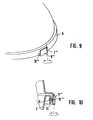
- FIGS. 9 and 10 schematically is an embodiment of a locking device according to the invention with a wing plate analogous to the Fig. 1-5 shown, but with the pivot axis of the pivot plate 9 '' in the FIGS. 9 and 10 not horizontally, ie parallel to Koffertrnenbene, but vertically, that is perpendicular to this Koffertrnenbene.
- the wing plate 9 "'in the embodiment according to Fig. 9 designed so that it projects beyond the edge 6 of the trunk lid and on the left, the pivot hinge 7 "'remote end, a locking member 10''carries, which engages under the sealing edge of the lower part.
- wing plate which in this case the lid edge 6 does not need to overlap down
- a locking pin 10 "' which is analogous to the embodiments of the Fig. 6 -8 engages in a recess 14 of the sealing edge 11 of the case bottom part 2.
Landscapes
- Engineering & Computer Science (AREA)
- Mechanical Engineering (AREA)
- Fittings On The Vehicle Exterior For Carrying Loads, And Devices For Holding Or Mounting Articles (AREA)
- Lock And Its Accessories (AREA)
- Supporting Of Heads In Record-Carrier Devices (AREA)
- Liquid Developers In Electrophotography (AREA)
Description
- Die Erfindung bezieht sich auf eine Schließsicherung für Dachkoffer zur Verhinderung eines Aufklappens des Kofferrandes durch zu hohen Winddruck oder bei Ausfall der normalen Schließanlage während der Fahrt, bei der ein Verriegelungsglied am einen Kofferteil in ein Gegenglied am anderen Kofferteil eingreift.
- Bei einer aus dem Gebrauchsmuster
DE 295 08 826 U1 bekannt gewordenen Schließsicherung der eingangs genannten Art ist am Deckelrand ein einschwenkbarer, in der eingeschwenkten Sicherungsstellung den Dichtrand des Unterteils frei untergreifender Sicherungshaken angelenkt, der beim Hochschwenken des Deckels unter den Rand des Bodenteils einhakt. Die Ausbildung ist dabei so getroffen, dass dieser Sicherungshaken durch sein Eigengewicht in die Verriegelungsstellung verschwenkt wird, in der er unterhalb des umbörtelten Randes des Unterteils des Dachkoffers liegt. Die Schließsicherung ist also ständig wirksam, was es erforderlich macht, dass der Benutzer zum Öffnen des Dachkoffers bei stehendem Fahrzeug diese Schließsicherung erst außer Betrieb setzen muss, indem er den Sicherungshaken zurückschwenkt, was aber wiederum Schwierigkeiten beim Betätigen der Schließeinrichtung des Deckels und dessen Hochschwenkens bereiten kann. - Der Erfindung liegt daher die Aufgabe zugrunde, eine Schließsicherung der eingangs genannten Art so auszubilden, dass sie bei stehendem Fahrzeug unwirksam ist und nur bei fahrendem Fahrzeug wirksam wird.
- Zur Lösung dieser Aufgabe ist erfindungsgemäß vorgesehen, dass das am einen Kofferteil angeordnete federnd in eine Nicht-Eingriffstellung vorgespannte Verriegelungsglied so ausgebildet und angeordnet ist, dass es durch den Fahrtwind nur während der Fahrt in seine Verriegelungsstellung verschwenkt wird.
- Ganz allgemein kann dabei das Verriegelungsglied mit einem Staudruck abhängigen Betätigungsglied beliebiger Art verbunden sein, das ausgehend von dem zunehmenden Staudruck mit zunehmender Geschwindigkeit des Fahrzeugs das Verriegelungsglied aus der Nicht-Eingriffsstellung in die Eingriffsstellung unter zusätzlichter Sicherungsverriegelung des Kofferdeckels am Kofferunterteil bewegt.
- Im einfachsten Fall ist dabei das am einen Kofferteil angeordnete Verriegelungsglied ein Verriegelungshaken oder Verriegelungsstift, der einen Randflansch des Gegenkofferteils unter- bzw. übergreift bzw. in eine Querausnehmung dieses Gegenkofferteils eingreift.
- Obgleich prinzipiell das Verriegelungsteil an jedem der Kofferteile angeordnet werden könnte, hat es sich für die Praxis als besonders zweckmäßig erwiesen, wenn das Verriegelungsteil am Dachkoffer-Oberteil angeordnet ist.
- Eine besonders einfache und betriebssichere Ausführung einer erfindungsgemäßen Schließsicherung ergibt sich in Ausgestaltung der Erfindung dadurch, dass das Verriegelungsglied an einer durch den Fahrtwind beaufschlagten und in die Verriegelungsstellung verstellbaren Druckverstellplatte angeordnet ist, die ihrerseits an einem am einen Kofferteil befestigbaren Fußteil federnd rückstellbar gelagert ist.
- Gemäß einer ersten Ausführung der vorliegenden Erfindung kann dabei diese Druckverstellplatte als Flügelplatte ausgebildet am vorzugsweise als Fußplatte ausgebildeten Fußteil schwenkbar gelagert sein, wobei die Schwenkachse sowohl horizontal, das heißt parallel zur Koffertrennebene, als auch vertikal, das heißt senkrecht zur Koffertrennebene angeordnet sein kann. Für die Praxis hat es sich aber als besonders zweckmäßig erwiesen, die horizontale Schwenklagerungsachse zu verwenden.
- Bei einer anderen Ausführung der Erfindung bildet die Druckverstellplatte den Kolben eines Staudruckzylinders, der beispielsweise am vorderen Rand des Dachkoffers angeordnet ist, wobei die Kolbenstange dieses Staudruckzylinders entweder das Verriegelungsglied trägt oder dieses Verriegelungsglied direkt bildet.
- Schließlich liegt es auch noch im Rahmen der Erfindung, dass die Druckverstellplatte eine das Verriegelungsglied tragende federelastische Membran ist.
- Weitere Vorteile und Einzelheiten der Erfindung ergeben sich aus der nachfolgenden Beschreibung einiger Ausführungsbeispiele sowie anhand der Zeichnungen. Dabei zeigen:
- Fig. 1
- eine Ansicht eines Dachkoffers von vorne mit einer am Deckel angeordneten erfindungsgemäßen Schließsicherung zum Untergreifen des Dichtrandes des Kofferunterteils in der Ruhestellung bei stehendem Fahrzeug gemäß einem ersten Ausführungsbeispiel,
- Fig. 2
- eine Ansicht des Dachkoffers von vorne in der eingeschwenkten Verriegelungsstellung während der Fahrt,
- Fig. 3
- einen Schnitt längs der Linie III - III in
Fig. 1 , wobei gestrichelt auch die Stellung des Verriegelungshakens in der Verriegelungsstellung nachFig. 2 eingezeichnet ist, - Fig. 4
- einen der
Fig. 3 entsprechenden Schnitt in einer Situation, in der durch den Fahrtwind der Dachkoffer am vorderen Ende geringfügig bis zum Wirksamwerden der Schließsicherung angehoben worden ist, - Fig. 5
- eine vergrößerte Detailansicht der Schwenklagerung der Anordnung nach den
Fig. 1 - 4 mit der Rückstellfeder, - Fig. 6
- eine perspektivische Explosionsdarstellung eines zweiten Ausführungsbeispiels einer als Staudruckzylinder ausgebildeten Ausführung einer erfindungsgemäßen Schließsicherung,
- Fig. 7
- einen Schnitt durch das vordere Ende des Dachkoffers mit der Schließsicherung gemäß
Fig. 6 in der Ruhestellung, - Fig. 8
- einen der
Fig. 7 entsprechenden Schnitt durch eine weitere Ausführung einer erfindungsgemäßen Schließsicherung, bei der die Druckverstellplatte als federelastische Membran ausgebildet ist, und - Fig. 9 und 10
- schematische Darstellungen der Ausgestaltung einer Schließsicherung mit schwenkbarer Flügelplatte, bei der die Schwenkachse vertikal angeordnet ist.
- Bei dem in den
Fig. 1 - 5 dargestellten ersten Ausführungsbeispiel der vorliegenden Erfindung erkennt man zunächst einen Dachkoffer 1 mit einem Kofferunterteil 2 und einem schwenkbar daran angelenkten Deckel 3, wobei es gleichgültig ist, ob die Schwenklagerung um die gegenüber der erkennbaren Vorderseite des Dachkoffers 1 abgelegene Hinterkante oder um eine der Seitenkanten des Deckels 3 erfolgt. Bei 4 ist eine erfindungsgemäße zusätzliche Schließsicherung angedeutet, die ein durch den Fahrtwind verursachtes Aufschwenken des Deckels 3 am vorderen Kofferende gegenüber dem Unterteil 2 während der Fahrt verhindert. Zu diesem Zweck ist die Schließsicherung 4 so ausgebildet, dass sie im Ruhestand, also bei stehendem Fahrzeug (Fig. 1 und3 ausgezogen gezeichnet) in einer durch eine Feder vorgespannten Nicht-Verriegelungsstellung angeordnet ist und nur durch den Fahrtdruck in die Verriegelungsstellung (Fig. 2 ,3 gestrichelt gezeichnet undFig. 4 ) verschwenkt wird. - Die Schließsicherung 4 nach den
Fig. 1 - 5 umfasst eine Fußplatte 5, die am Rand 6 des Deckels 3 befestigt ist, und eine an dieser Fußplatte 5 über ein Schwenklager 7 mit einer Rückstellfeder 8 schwenkbar gelagerten Druckverstellplatte, die hier als Flügelplatte 9 ausgebildet ist, und die einen Verriegelungshaken 10 trägt. Dieser Verriegelungshaken 10 ist in der Ruhestellung, das heißt bei stehendem Fahrzeug, in der inFig. 3 ausgezogen dargestellten nach außen verschwenkten Stellung angeordnet und durch die Rückstellfeder in dieser Stellung gehalten, so dass der Deckel 3 ohne Weiteres geöffnet werden kann. Die Schließsicherung 4 ist also bei stehendem Fahrzeug überhaupt nicht wirksam. - Erst durch den Fahrtwind während der Fahrt wird die Flügelplatte 9 nach rechts in die in
Fig. 3 gestrichelt eingezeichnete Stellung verschwenkt, so dass nunmehr der Verriegelungshaken 10 während der Fahrt immer unterhalb eines Dichtrandes 11 des Koffer-Unterteils 2 angeordnet ist, so dass bei zu hohem Winddruck, wenn sich der Deckel 3 tatsächlich etwas nach oben öffnen will, die inFig. 4 skizzierte Fangsituation eintritt, bei der der Verriegelungshaken 10 nach nur einem relativ geringem Öffnungshub des Deckels 3 ein weiteres Aufgehen sicher verhindert. - Die
Fig. 6 und 7 zeigen ein zweites Ausführungsbeispiel, bei dem die Schließsicherung 4' ein als Staudruckkolben ausgebildetes Fußteil 5' und einen gegen eine Federanordnung 8' durch den in Richtung einer Achse 12 einwirkenden Winddruck verschiebbaren, eine Druckverstellplatte bildenden Kolben 9' aufweist. Dessen Kolbenstange 10 bildet in diesem Fall direkt einen Verriegelungsstift, der den Boden des Staudruckzylinders untersetzend, aus der inFig. 7 gezeigten Ruhestellung an der vorderen Spitze des Dachkoffers durch den in Richtung des Pfeils 13 einwirkenden Fahrtwind in eine Verriegelungsausnehmung 14 des Dichtrandes 11 des Kofferunterteils 2 eingedrückt werden kann. - Die
Fig. 8 zeigt eine Alternative, bei der anstelle eines durch den Winddruck verschiebbaren Kolbens eine federelastische Membran 9" vorgesehen ist, an der direkt ein Verriegelungsstift 10" befestigt ist. Auch hier ist die Ausbildung wieder so getroffen, dass in der Ruhestellung, also bei stehendem Fahrzeug, der Verriegelungsstift 10" noch nicht in die Verriegelungsaussparung 14 des Kofferunterteils eingreift, sondern erst wenn bei einer bestimmten Geschwindigkeit ausreichender Winddruck herrscht, so dass die Membran sich entsprechend durchbiegt. Die Verriegelung wird ja auch erst in der Fahrt benötigt, da das zu verhindernde Öffnen des Deckels bei der Fahrt durch den Fahrtwind eine gewisse Mindestgeschwindigkeit voraussetzt. - In den
Fig. 9 und 10 ist schematisch ein Ausführungsbeispiel einer erfindungsgemäßen Schließsicherung mit einer Flügelplatte analog zu denFig. 1 - 5 dargestellt, wobei aber die Schwenkachse der Schwenkplatte 9"' in denFig. 9 und 10 nicht horizontal, also parallel zur Koffertrennebene, sondern vertikal, also senkrecht zu dieser Koffertrennebene verläuft. Die Flügelplatte 9"' ist beim Ausführungsbeispiel nachFig. 9 so ausgebildet, dass sie den Rand 6 des Kofferdeckels überragt und am linken, dem Schwenkscharnier 7"' abgelegenen Ende, ein Verriegelungsglied 10"' trägt, welches den Dichtrand des Unterteils untergreift. Bei der Ausführungsform nachFig. 10 ist statt dessen die Flügelplatte, die in diesem Fall den Deckelrand 6 nach unten nicht übergreifen braucht, mit einem Verriegelungsstift 10"' versehen, der analog zu den Ausführungsformen nach denFig. 6 -8 in eine Aussparung 14 des Dichtrandes 11 des Kofferunterteils 2 eingreift.
Claims (10)
- Schließsicherung für Dachkoffer zur Verhinderung eines Aufklappens des Kofferrandes durch zu hohen Winddruck oder bei Ausfall der normalen Schließanlage während der Fahrt, bei der ein Verriegelungsglied am einen Kofferteil in ein Gegenglied am anderen Kofferteil eingreift, dadurch gekennzeichnet, dass das am einen Kofferteil (3) angeordnete federnd in eine Nicht-Eingriffstellung vorgespannte Verriegelungsglied so ausgebildet und angeordnet ist, dass es durch den Fahrtwind nur während der Fahrt in seine Verriegelungsstellung verschwenkt wird.
- Schließsicherung nach Anspruch 1, dadurch gekennzeichnet, dass das Verriegelungsglied mit einem staudruckabhängigen Betätigungsglied verbunden ist.
- Schließsicherung nach Anspruch 1 oder 2, dadurch gekennzeichnet, dass das am einen Kofferteil angeordnete Verriegelungsglied ein Verriegelungshaken (10) oder Verriegelungsstift (10', 10") ist, der einen Randflansch (11) des Gegenkofferteils (2) untergreift oder übergreift bzw. in eine Querausnehmung (14) dieses Gegenkofferteils (2) eingreift.
- Schließsicherung nach einem der Ansprüche 1 bis 3, dadurch gekennzeichnet, dass das Verriegelungsglied an einer durch den Fahrtwind beaufschlagten und in die Verriegelungsstellung verstellbaren Druckverstellplatte (9, 9', 9") angeordnet ist, die ihrerseits an einem am einen Kofferteil befestigbaren Fußteil federnd rückstellbar gelagert ist.
- Schließsicherung nach Anspruch 4, dadurch gekennzeichnet, dass die Druckverstellplatte als Flügelplatte (9) am vorzugsweise als Fußplatte (5) ausgebildeten Fußteil schwenkbar gelagert ist.
- Schließsicherung nach Anspruch 5, dadurch gekennzeichnet, dass die Schwenkachse horizontal d. h. parallel zur Koffertrennebene angeordnet ist.
- Schließsicherung nach Anspruch 5, dadurch gekennzeichnet, dass die Schwenkachse vertikal d. h. senkrecht zur Koffertrennebene angeordnet ist.
- Schließsicherung nach Anspruch 4, dadurch gekennzeichnet, dass die Druckverstellplatte den Kolben (9') eines Staudruckzylinders bildet, dessen Kolbenstange (10") das Verriegelungsglied trägt oder direkt bildet.
- Schließsicherung nach Anspruch 4, dadurch gekennzeichnet, dass die Druckverstellplatte eine das Verriegelungsglied tragende federelastische Membran (9") ist.
- Schließsicherung nach einem der Ansprüche 1 bis 9, dadurch gekennzeichnet, dass das Verriegelungsglied am Dachkoffer (3) angeordnet ist.
Applications Claiming Priority (2)
| Application Number | Priority Date | Filing Date | Title |
|---|---|---|---|
| DE102004043962A DE102004043962A1 (de) | 2004-09-11 | 2004-09-11 | Staudruckabhängige Dachkofferverriegelung |
| PCT/DE2005/001512 WO2006026957A1 (de) | 2004-09-11 | 2005-08-30 | Staudruckabhängige dachkofferverriegelung |
Publications (2)
| Publication Number | Publication Date |
|---|---|
| EP1786652A1 EP1786652A1 (de) | 2007-05-23 |
| EP1786652B1 true EP1786652B1 (de) | 2008-03-12 |
Family
ID=35262207
Family Applications (1)
| Application Number | Title | Priority Date | Filing Date |
|---|---|---|---|
| EP05779656A Expired - Lifetime EP1786652B1 (de) | 2004-09-11 | 2005-08-30 | Staudruckabh[ngige dachkofferverriegelung |
Country Status (6)
| Country | Link |
|---|---|
| US (1) | US20080093402A1 (de) |
| EP (1) | EP1786652B1 (de) |
| JP (1) | JP4610617B2 (de) |
| AT (1) | ATE388855T1 (de) |
| DE (2) | DE102004043962A1 (de) |
| WO (1) | WO2006026957A1 (de) |
Families Citing this family (2)
| Publication number | Priority date | Publication date | Assignee | Title |
|---|---|---|---|---|
| AU2005225151B2 (en) * | 2000-05-15 | 2008-05-29 | F. Hoffmann-La Roche Ag | New pharmaceutical composition |
| CN106760988B (zh) * | 2017-01-24 | 2019-01-15 | 东莞市怡丰锁业有限公司 | 一种操作简便的薄型扣锁 |
Family Cites Families (13)
| Publication number | Priority date | Publication date | Assignee | Title |
|---|---|---|---|---|
| GB214502A (en) * | 1923-06-25 | 1924-04-24 | Jacob Thomas Kilmer Barber | Automatic locking device for the doors of vehicles |
| GB266171A (en) * | 1926-05-07 | 1927-02-24 | Alexander Wallace | Improvements in and connected with means for automatically locking and unlocking the doors of railway carriage and other vehicles |
| GB1276011A (en) * | 1968-05-17 | 1972-06-01 | Paul Parry | Improvements in or relating to a clamping device |
| US4512598A (en) * | 1980-10-21 | 1985-04-23 | D. G. Shelter Products Company | Releasable latch bracket means for a vehicle sunroof |
| US4595230A (en) * | 1983-06-10 | 1986-06-17 | Top Off Corp. | Method and apparatus for converting a hardtop vehicle to a removable top vehicle |
| DE4001141C1 (en) * | 1990-01-17 | 1991-04-18 | Mercedes-Benz Aktiengesellschaft, 7000 Stuttgart, De | Safety catch for car bonnet - incorporates separate control hook and safety hook |
| US5360254A (en) * | 1992-02-26 | 1994-11-01 | Honda Giken Kogyo Kabushiki Kaisha | Automobile with movable roof storable in trunk lid |
| JPH0642427U (ja) * | 1992-11-10 | 1994-06-07 | タキロン株式会社 | 車載トランク装置 |
| DE29508826U1 (de) | 1995-05-27 | 1995-08-10 | Jetbag Gmbh, 92318 Neumarkt | Schließsicherung für Dachkoffer |
| JP3294770B2 (ja) * | 1996-08-27 | 2002-06-24 | 三井金属鉱業株式会社 | ポップアップルーフ車 |
| ITBZ970037A1 (it) * | 1997-06-25 | 1998-12-28 | Jul Sinn | Contenitore portabagagli per autovetture |
| US20020167175A1 (en) * | 2001-01-30 | 2002-11-14 | Robert Bosch Gmbh | Motor vehicle gate lock arrangement |
| US6808080B2 (en) * | 2002-03-08 | 2004-10-26 | Delaware Capital Formation, Inc. | Container latching method and apparatus |
-
2004
- 2004-09-11 DE DE102004043962A patent/DE102004043962A1/de not_active Ceased
-
2005
- 2005-08-30 AT AT05779656T patent/ATE388855T1/de not_active IP Right Cessation
- 2005-08-30 JP JP2007530579A patent/JP4610617B2/ja not_active Expired - Fee Related
- 2005-08-30 US US11/661,066 patent/US20080093402A1/en not_active Abandoned
- 2005-08-30 DE DE502005003236T patent/DE502005003236D1/de not_active Expired - Lifetime
- 2005-08-30 WO PCT/DE2005/001512 patent/WO2006026957A1/de not_active Ceased
- 2005-08-30 EP EP05779656A patent/EP1786652B1/de not_active Expired - Lifetime
Also Published As
| Publication number | Publication date |
|---|---|
| ATE388855T1 (de) | 2008-03-15 |
| WO2006026957A1 (de) | 2006-03-16 |
| DE102004043962A1 (de) | 2006-03-30 |
| JP4610617B2 (ja) | 2011-01-12 |
| EP1786652A1 (de) | 2007-05-23 |
| JP2008512295A (ja) | 2008-04-24 |
| DE502005003236D1 (de) | 2008-04-24 |
| US20080093402A1 (en) | 2008-04-24 |
Similar Documents
| Publication | Publication Date | Title |
|---|---|---|
| EP2147178B1 (de) | Scharnieranordnung | |
| DE102007045394B4 (de) | Überkopfablagefach für ein Fahrzeug | |
| EP0292789A1 (de) | Dachfenster | |
| DE10111096A1 (de) | Anordnung einer Frontklappe an einem Fahrzeug | |
| DE1801310A1 (de) | Selbsthemmendes Scharnier | |
| DE4225670C2 (de) | Drehfallenschloß mit Fanghaken | |
| DE202004002480U1 (de) | Anordnung einer Frontklappe mit Verstellhebel an einem Fahrzeug | |
| DE1653994B2 (de) | Kraftfahrzeugtürverschluß | |
| DE673453C (de) | Federndes Klappenscharnier fuer OEffnungen an Luftfahrzeugen | |
| DE4308675C2 (de) | Weitwinkel-Kraftwagentürscharnier | |
| WO2006026957A1 (de) | Staudruckabhängige dachkofferverriegelung | |
| DE102007012265A1 (de) | Türbeschlag | |
| DE3930149A1 (de) | Tuerschloss | |
| DE1970380U (de) | Scharnier fuer fahrzeugtueren. | |
| DE10044006B4 (de) | Türhalter für Türen von Lastkraftwagen | |
| DE3442835C2 (de) | Verschlußvorrichtung für eine abklappbare Abdeckplatte einer Gehäuseöffnung an einem Haushaltgerät | |
| DE4125428A1 (de) | Aufstellvorrichtung fuer die motor- oder kofferraumhaube eines kraftfahrzeuges | |
| DE4021779B4 (de) | Sicherungsschere | |
| DE2415888A1 (de) | An ein tuerscharnier angeschlossener tuerfeststeller, insbesondere fuer kraftwagentueren | |
| DE815153C (de) | Vorrichtung zur Betaetigung eines Tuerverschlusses an Fahrzeugen | |
| DE9206175U1 (de) | Lagerbock für einen Klappgriff | |
| DE102012218038B4 (de) | Fahrzeug mit einer Verschlussanordnung | |
| DE102004024842C5 (de) | Scharnierbeschlag für eine KFZ-Tür | |
| DE9316196U1 (de) | Drehstange mit Verschlußhaken eines Drehstangenverschlusses für Klappen oder Türen von Nutzfahrzeugen, Transportbehältern o.dgl. | |
| DE7617827U1 (de) | Tuergriff, insbesondere fuer kraftfahrzeuge |
Legal Events
| Date | Code | Title | Description |
|---|---|---|---|
| PUAI | Public reference made under article 153(3) epc to a published international application that has entered the european phase |
Free format text: ORIGINAL CODE: 0009012 |
|
| 17P | Request for examination filed |
Effective date: 20070213 |
|
| AK | Designated contracting states |
Kind code of ref document: A1 Designated state(s): AT BE BG CH CY CZ DE DK EE ES FI FR GB GR HU IE IS IT LI LT LU LV MC NL PL PT RO SE SI SK TR |
|
| GRAP | Despatch of communication of intention to grant a patent |
Free format text: ORIGINAL CODE: EPIDOSNIGR1 |
|
| DAX | Request for extension of the european patent (deleted) | ||
| GRAS | Grant fee paid |
Free format text: ORIGINAL CODE: EPIDOSNIGR3 |
|
| GRAA | (expected) grant |
Free format text: ORIGINAL CODE: 0009210 |
|
| AK | Designated contracting states |
Kind code of ref document: B1 Designated state(s): AT BE BG CH CY CZ DE DK EE ES FI FR GB GR HU IE IS IT LI LT LU LV MC NL PL PT RO SE SI SK TR |
|
| REG | Reference to a national code |
Ref country code: GB Ref legal event code: FG4D Free format text: NOT ENGLISH |
|
| REG | Reference to a national code |
Ref country code: CH Ref legal event code: EP |
|
| REG | Reference to a national code |
Ref country code: IE Ref legal event code: FG4D Free format text: LANGUAGE OF EP DOCUMENT: GERMAN |
|
| REF | Corresponds to: |
Ref document number: 502005003236 Country of ref document: DE Date of ref document: 20080424 Kind code of ref document: P |
|
| PG25 | Lapsed in a contracting state [announced via postgrant information from national office to epo] |
Ref country code: LT Free format text: LAPSE BECAUSE OF FAILURE TO SUBMIT A TRANSLATION OF THE DESCRIPTION OR TO PAY THE FEE WITHIN THE PRESCRIBED TIME-LIMIT Effective date: 20080312 Ref country code: FI Free format text: LAPSE BECAUSE OF FAILURE TO SUBMIT A TRANSLATION OF THE DESCRIPTION OR TO PAY THE FEE WITHIN THE PRESCRIBED TIME-LIMIT Effective date: 20080312 |
|
| NLV1 | Nl: lapsed or annulled due to failure to fulfill the requirements of art. 29p and 29m of the patents act | ||
| ET | Fr: translation filed | ||
| PG25 | Lapsed in a contracting state [announced via postgrant information from national office to epo] |
Ref country code: PL Free format text: LAPSE BECAUSE OF FAILURE TO SUBMIT A TRANSLATION OF THE DESCRIPTION OR TO PAY THE FEE WITHIN THE PRESCRIBED TIME-LIMIT Effective date: 20080312 Ref country code: LV Free format text: LAPSE BECAUSE OF FAILURE TO SUBMIT A TRANSLATION OF THE DESCRIPTION OR TO PAY THE FEE WITHIN THE PRESCRIBED TIME-LIMIT Effective date: 20080312 Ref country code: SI Free format text: LAPSE BECAUSE OF FAILURE TO SUBMIT A TRANSLATION OF THE DESCRIPTION OR TO PAY THE FEE WITHIN THE PRESCRIBED TIME-LIMIT Effective date: 20080312 |
|
| REG | Reference to a national code |
Ref country code: IE Ref legal event code: FD4D |
|
| PG25 | Lapsed in a contracting state [announced via postgrant information from national office to epo] |
Ref country code: SE Free format text: LAPSE BECAUSE OF FAILURE TO SUBMIT A TRANSLATION OF THE DESCRIPTION OR TO PAY THE FEE WITHIN THE PRESCRIBED TIME-LIMIT Effective date: 20080612 Ref country code: ES Free format text: LAPSE BECAUSE OF FAILURE TO SUBMIT A TRANSLATION OF THE DESCRIPTION OR TO PAY THE FEE WITHIN THE PRESCRIBED TIME-LIMIT Effective date: 20080623 Ref country code: PT Free format text: LAPSE BECAUSE OF FAILURE TO SUBMIT A TRANSLATION OF THE DESCRIPTION OR TO PAY THE FEE WITHIN THE PRESCRIBED TIME-LIMIT Effective date: 20080818 Ref country code: SK Free format text: LAPSE BECAUSE OF FAILURE TO SUBMIT A TRANSLATION OF THE DESCRIPTION OR TO PAY THE FEE WITHIN THE PRESCRIBED TIME-LIMIT Effective date: 20080312 Ref country code: CZ Free format text: LAPSE BECAUSE OF FAILURE TO SUBMIT A TRANSLATION OF THE DESCRIPTION OR TO PAY THE FEE WITHIN THE PRESCRIBED TIME-LIMIT Effective date: 20080312 |
|
| PG25 | Lapsed in a contracting state [announced via postgrant information from national office to epo] |
Ref country code: RO Free format text: LAPSE BECAUSE OF FAILURE TO SUBMIT A TRANSLATION OF THE DESCRIPTION OR TO PAY THE FEE WITHIN THE PRESCRIBED TIME-LIMIT Effective date: 20080312 Ref country code: NL Free format text: LAPSE BECAUSE OF FAILURE TO SUBMIT A TRANSLATION OF THE DESCRIPTION OR TO PAY THE FEE WITHIN THE PRESCRIBED TIME-LIMIT Effective date: 20080312 |
|
| PG25 | Lapsed in a contracting state [announced via postgrant information from national office to epo] |
Ref country code: IS Free format text: LAPSE BECAUSE OF FAILURE TO SUBMIT A TRANSLATION OF THE DESCRIPTION OR TO PAY THE FEE WITHIN THE PRESCRIBED TIME-LIMIT Effective date: 20080712 |
|
| PLBE | No opposition filed within time limit |
Free format text: ORIGINAL CODE: 0009261 |
|
| STAA | Information on the status of an ep patent application or granted ep patent |
Free format text: STATUS: NO OPPOSITION FILED WITHIN TIME LIMIT |
|
| PG25 | Lapsed in a contracting state [announced via postgrant information from national office to epo] |
Ref country code: IE Free format text: LAPSE BECAUSE OF FAILURE TO SUBMIT A TRANSLATION OF THE DESCRIPTION OR TO PAY THE FEE WITHIN THE PRESCRIBED TIME-LIMIT Effective date: 20080312 Ref country code: DK Free format text: LAPSE BECAUSE OF FAILURE TO SUBMIT A TRANSLATION OF THE DESCRIPTION OR TO PAY THE FEE WITHIN THE PRESCRIBED TIME-LIMIT Effective date: 20080312 |
|
| 26N | No opposition filed |
Effective date: 20081215 |
|
| PG25 | Lapsed in a contracting state [announced via postgrant information from national office to epo] |
Ref country code: MC Free format text: LAPSE BECAUSE OF NON-PAYMENT OF DUE FEES Effective date: 20080831 |
|
| PG25 | Lapsed in a contracting state [announced via postgrant information from national office to epo] |
Ref country code: BG Free format text: LAPSE BECAUSE OF FAILURE TO SUBMIT A TRANSLATION OF THE DESCRIPTION OR TO PAY THE FEE WITHIN THE PRESCRIBED TIME-LIMIT Effective date: 20080612 Ref country code: EE Free format text: LAPSE BECAUSE OF FAILURE TO SUBMIT A TRANSLATION OF THE DESCRIPTION OR TO PAY THE FEE WITHIN THE PRESCRIBED TIME-LIMIT Effective date: 20080312 |
|
| PG25 | Lapsed in a contracting state [announced via postgrant information from national office to epo] |
Ref country code: BE Free format text: LAPSE BECAUSE OF NON-PAYMENT OF DUE FEES Effective date: 20080831 |
|
| PG25 | Lapsed in a contracting state [announced via postgrant information from national office to epo] |
Ref country code: IT Free format text: LAPSE BECAUSE OF FAILURE TO SUBMIT A TRANSLATION OF THE DESCRIPTION OR TO PAY THE FEE WITHIN THE PRESCRIBED TIME-LIMIT Effective date: 20080312 |
|
| PG25 | Lapsed in a contracting state [announced via postgrant information from national office to epo] |
Ref country code: CY Free format text: LAPSE BECAUSE OF FAILURE TO SUBMIT A TRANSLATION OF THE DESCRIPTION OR TO PAY THE FEE WITHIN THE PRESCRIBED TIME-LIMIT Effective date: 20080312 |
|
| PG25 | Lapsed in a contracting state [announced via postgrant information from national office to epo] |
Ref country code: AT Free format text: LAPSE BECAUSE OF NON-PAYMENT OF DUE FEES Effective date: 20080830 |
|
| REG | Reference to a national code |
Ref country code: CH Ref legal event code: PL |
|
| PG25 | Lapsed in a contracting state [announced via postgrant information from national office to epo] |
Ref country code: LI Free format text: LAPSE BECAUSE OF NON-PAYMENT OF DUE FEES Effective date: 20090831 Ref country code: CH Free format text: LAPSE BECAUSE OF NON-PAYMENT OF DUE FEES Effective date: 20090831 |
|
| PG25 | Lapsed in a contracting state [announced via postgrant information from national office to epo] |
Ref country code: LU Free format text: LAPSE BECAUSE OF NON-PAYMENT OF DUE FEES Effective date: 20080830 Ref country code: HU Free format text: LAPSE BECAUSE OF FAILURE TO SUBMIT A TRANSLATION OF THE DESCRIPTION OR TO PAY THE FEE WITHIN THE PRESCRIBED TIME-LIMIT Effective date: 20080913 |
|
| PG25 | Lapsed in a contracting state [announced via postgrant information from national office to epo] |
Ref country code: TR Free format text: LAPSE BECAUSE OF FAILURE TO SUBMIT A TRANSLATION OF THE DESCRIPTION OR TO PAY THE FEE WITHIN THE PRESCRIBED TIME-LIMIT Effective date: 20080312 |
|
| PG25 | Lapsed in a contracting state [announced via postgrant information from national office to epo] |
Ref country code: GR Free format text: LAPSE BECAUSE OF FAILURE TO SUBMIT A TRANSLATION OF THE DESCRIPTION OR TO PAY THE FEE WITHIN THE PRESCRIBED TIME-LIMIT Effective date: 20080613 |
|
| REG | Reference to a national code |
Ref country code: DE Ref legal event code: R082 Ref document number: 502005003236 Country of ref document: DE |
|
| PGFP | Annual fee paid to national office [announced via postgrant information from national office to epo] |
Ref country code: GB Payment date: 20140827 Year of fee payment: 10 Ref country code: FR Payment date: 20140808 Year of fee payment: 10 |
|
| GBPC | Gb: european patent ceased through non-payment of renewal fee |
Effective date: 20150830 |
|
| REG | Reference to a national code |
Ref country code: FR Ref legal event code: ST Effective date: 20160429 |
|
| PG25 | Lapsed in a contracting state [announced via postgrant information from national office to epo] |
Ref country code: GB Free format text: LAPSE BECAUSE OF NON-PAYMENT OF DUE FEES Effective date: 20150830 |
|
| PG25 | Lapsed in a contracting state [announced via postgrant information from national office to epo] |
Ref country code: FR Free format text: LAPSE BECAUSE OF NON-PAYMENT OF DUE FEES Effective date: 20150831 |
|
| PGFP | Annual fee paid to national office [announced via postgrant information from national office to epo] |
Ref country code: DE Payment date: 20160823 Year of fee payment: 12 |
|
| REG | Reference to a national code |
Ref country code: DE Ref legal event code: R119 Ref document number: 502005003236 Country of ref document: DE |
|
| PG25 | Lapsed in a contracting state [announced via postgrant information from national office to epo] |
Ref country code: DE Free format text: LAPSE BECAUSE OF NON-PAYMENT OF DUE FEES Effective date: 20180301 |
|
| P01 | Opt-out of the competence of the unified patent court (upc) registered |
Effective date: 20230528 |