EP1785534A1 - Ablaufvorrichtung für eine bodengleiche Dusche - Google Patents
Ablaufvorrichtung für eine bodengleiche Dusche Download PDFInfo
- Publication number
- EP1785534A1 EP1785534A1 EP06123934A EP06123934A EP1785534A1 EP 1785534 A1 EP1785534 A1 EP 1785534A1 EP 06123934 A EP06123934 A EP 06123934A EP 06123934 A EP06123934 A EP 06123934A EP 1785534 A1 EP1785534 A1 EP 1785534A1
- Authority
- EP
- European Patent Office
- Prior art keywords
- housing part
- housing
- drain
- grate
- shaped
- Prior art date
- Legal status (The legal status is an assumption and is not a legal conclusion. Google has not performed a legal analysis and makes no representation as to the accuracy of the status listed.)
- Granted
Links
Images


Classifications
-
- E—FIXED CONSTRUCTIONS
- E03—WATER SUPPLY; SEWERAGE
- E03C—DOMESTIC PLUMBING INSTALLATIONS FOR FRESH WATER OR WASTE WATER; SINKS
- E03C1/00—Domestic plumbing installations for fresh water or waste water; Sinks
- E03C1/12—Plumbing installations for waste water; Basins or fountains connected thereto; Sinks
- E03C1/22—Outlet devices mounted in basins, baths, or sinks
-
- E—FIXED CONSTRUCTIONS
- E03—WATER SUPPLY; SEWERAGE
- E03F—SEWERS; CESSPOOLS
- E03F5/00—Sewerage structures
- E03F5/04—Gullies inlets, road sinks, floor drains with or without odour seals or sediment traps
- E03F5/0407—Floor drains for indoor use
- E03F5/0408—Floor drains for indoor use specially adapted for showers
-
- E—FIXED CONSTRUCTIONS
- E03—WATER SUPPLY; SEWERAGE
- E03F—SEWERS; CESSPOOLS
- E03F5/00—Sewerage structures
- E03F5/04—Gullies inlets, road sinks, floor drains with or without odour seals or sediment traps
- E03F2005/0412—Gullies inlets, road sinks, floor drains with or without odour seals or sediment traps with means for adjusting their position with respect to the surrounding surface
- E03F2005/0413—Gullies inlets, road sinks, floor drains with or without odour seals or sediment traps with means for adjusting their position with respect to the surrounding surface for height adjustment
-
- E—FIXED CONSTRUCTIONS
- E03—WATER SUPPLY; SEWERAGE
- E03F—SEWERS; CESSPOOLS
- E03F5/00—Sewerage structures
- E03F5/04—Gullies inlets, road sinks, floor drains with or without odour seals or sediment traps
- E03F2005/0416—Gullies inlets, road sinks, floor drains with or without odour seals or sediment traps with an odour seal
- E03F2005/0418—Gullies inlets, road sinks, floor drains with or without odour seals or sediment traps with an odour seal in the form of a bell siphon
Definitions
- the invention relates to a sanitary drainage device for producing a water drain embedded in a floor, in particular for producing a floor-level shower, with a grate, a housing having a drain opening and the grate, an odor trap and a drain pipe detachably connectable with a drainage pipe.
- the functionally reliable embedding of the drain in the screed is not always easy. Occasionally, during or after the screed is laid, it is found that the drain has been positioned too high or too low relative to the top of the screed. Leveling is then often difficult and can lead to sealing defects as well as slope failure and resulting water drainage problems.
- the present invention is therefore an object of the invention to provide a drain device of the type mentioned, which overcomes the above problems.
- the drainage device comprises a grate, a housing having a drain opening and carrying the grate, an odor trap and a drain neck detachably connectable to a drainage line.
- the housing is constructed in the form of a box-shaped housing from a cup-shaped housing lower part and a lid-like housing upper part, wherein the odor trap is arranged in its position relative to the housing upper part and / or the lower housing part adjustable in the housing.
- the upper housing part is height adjustable relative to the lower housing part connected to the same and provided with anchoring means which serve to anchor the upper housing part in a screed.
- the housing of the drainage device according to the invention thus advantageously allows a height adjustment of the sealing level of the process until immediately before the screed laying.
- the process in particular its odor trap, is protected by the housing against damage before or during screed laying.
- the anchoring means of the housing upper part cause a stable and reliable connection of the housing to the screed.
- a structure-borne noise decoupling of the housing to the subfloor (concrete floor) achieved or enabled.
- a damping layer for example a foam film or the like, can be arranged in advance underneath the housing, ie below the housing lower part.
- the height adjustability of the housing and its protective function can be structurally relatively easily realized by the upper housing part is designed such that it surrounds the lower edge of the housing at the edge.
- the height of the upper housing part relative to the lower housing part can preferably be adjusted and / or determined by means of screws fastened to the upper housing part and / or to the lower housing part.
- the lower housing part is provided with fastening straps.
- the lower part of the housing can thus be fixed with screws to the subfloor.
- a piece of pipe is arranged between the odor trap and the outlet nozzle, which is connected to both the odor trap and the drainage spigot and liquid-tight. If it should turn out during the subsequent screed laying that the box-shaped housing is positioned at the wrong height, the housing can also be subsequently corrected in the height in both directions by the double joint at the outlet connection.
- the upper housing side may have an annular, the drain opening surrounding recess in which an annular disc-shaped element having an eccentrically arranged aperture, is rotatably received, wherein the annular disk-shaped element has a recess on the upper side, in which Grate is arranged substantially horizontally displaceable.
- This embodiment also allows a fit of the grate in a tile grid even when the drainage device is embedded in the hardened screed.
- the annular disk-shaped element is provided on the upper side with a plurality of grooves which open at the opening.
- the grooves extend from the opening in the radial direction and each have a groove bottom inclined in the direction of the opening.
- a further preferred embodiment of the drainage device according to the invention consists in that one or more frame-shaped washers are assigned to the grate or to a grate-receiving frame. By means of one or more of these washers, the height of the upper edge of the grate can be adapted to different tile or natural stone slab thicknesses.
- the drain device 1 shown in the drawing is in particular for producing a floor-level shower certainly.
- the drain 3 provided with an odor trap 2 is arranged in a two-part, box-shaped housing 4.
- the housing 4 of the drainage device 1 is constructed from a lower housing part 4.1 and a housing upper part 4.2 having a drain opening 5 and thus enables height adjustment for adaptation to the floor construction.
- the lower housing part 4.1 is formed shell-shaped and has a bottom 6 and four walls oriented substantially at right angles to each other, wherein the cover-like, also shell-shaped upper housing part 4.2 surrounds the lower housing part 4.1 edge.
- the designated 7 wall of the housing base 4.1 has a recess 8 for the passage of a drain nozzle 9.
- a recess 10 is provided in the housing lower part 4.1 enclosing wall of the housing upper part 4.2 . Both recesses 8 and 10 are substantially U-shaped and extend to the upper edge of the housing base 4.1 or to the lower edge of the upper housing part 4.2.
- the opposite walls 7 and 11 of the lower housing part 4.1 are provided with threaded holes, are screwed into the locking screws 12, which pass through vertically extending slots 13 in the opposite walls of the upper housing part 4.2.
- Structure-borne sound damping means 14 are arranged between the mutually facing walls of the two housing parts 4.1 and 4.2.
- the structure-borne noise damping means 14 may consist, for example, of foam strips glued to the inside of the walls of the housing upper part, in particular of foam rubber strips.
- the lower housing part 4.1 and the upper housing part 4.2 are preferably made of plastic, for example made of fiber-reinforced polypropylene, acrylonitrile-butadiene-styrene (ABS) or other materials.
- plastic for example made of fiber-reinforced polypropylene, acrylonitrile-butadiene-styrene (ABS) or other materials.
- anchoring means 16 serve to establish a stable connection of the housing to the surrounding screed.
- the anchoring means 16 also reinforce the upper housing part 4.2 and are formed in this embodiment in the form of corrugated ribs.
- the upper side of the upper housing part 4.2 has a grid-shaped structure 17, which consists of lattice-like grooves 18 and flat, rectangular elevations 19. Reinforcing webs 20 are integrally formed on the underside of the cover-like housing upper part 4.2.
- the drain 3 located in the box-shaped housing 4 has an odor trap 2, which is formed from a cup-shaped plastic part 2.1 into which a nozzle-shaped separating channel protrudes 2.2 whose lower edge defines a deflection and the bottom of the cup-shaped plastic part 2.1 is spaced.
- a bell-shaped elevation 2.3 is formed, which projects into the separation channel 2.2.
- the pot-shaped plastic part 2.1 has a circumferential overflow edge 2.4, which, viewed from the outside, merges into an annular overflow channel 2.5, which in turn is inserted into a nozzle-shaped section 2.6 passes.
- the annular overflow channel 2.5 is formed in the direction of the nozzle-shaped portion 2.6 with a slope.
- the odor trap 2 also has an annular cover part 2.7, which covers the annular overflow channel 2.5 liquid-tight and at its opening 2.8 liquid-tight with the protruding into the cup-shaped plastic part 2.1 separation channel 2.2 is connected.
- the nozzle-shaped portion 2.6 of the drain or odor trap has a spherical thickening, which forms a ball joint together with a pipe section 21.
- the pipe section 21 also has a spherical thickening, which forms a ball joint with the protruding from the box-shaped housing 4 outlet pipe 9.
- annular grooves 22, 23 are formed, which serve to receive sealing rings (not shown in Figure 2).
- the arranged in the box-shaped housing 4, provided with the odor trap 2 3 is a separately manufactured with respect to the housing 4 component of theticianvorroplasty invention.
- the upper housing part 4.2 has on the upper side an annular, the drain opening 5 surrounding recess 24.
- an annular disk-shaped element 25 is rotatably received, which has an eccentrically arranged opening 26.
- Die ⁇ réelle 26 ist in der Ausbloodung 26 anlogue.
- a flat, substantially flat recess 27 is formed, in which a grate 28 substantially horizontally displaceable is arranged.
- the recess 27 has a substantially rectangular, preferably square shape, which is larger than a grate 28 receiving frame 29. The displacement of the grate 28 is possible in the plane of the recess 27 in at least two transverse directions.
- the frame 29 is provided with a plurality of frame-shaped washers 30, 31, 32 having a different thickness.
- the washers 30, 31, 32 are latched to each other and with the grate 28 receiving frame 29 or positively connected.
- the plate-shaped, annular disk-shaped element 25 has on the upper side a plurality of grooves or grooves 33, which open at the opening 26. Starting from the aperture 26, the grooves 33 extend substantially radially and terminate at a distance from the outer edge of the annular disk-shaped element 25.
- the grooves 33 preferably each have a groove bottom inclined in the direction of the aperture 26.
- the box-shaped drainage device 1 To assemble the box-shaped drainage device 1 is placed on the bare floor of the shower and bolted to the tabs 15. Thereafter, the height of the box-shaped housing 4 is adjusted and fixed with the lateral locking screws 12, that the upper edge (top) of the lid-like housing upper part 4.2 corresponds to the height (top edge) of the screed to be introduced. Subsequently, the flow is located in the box-shaped housing 4 3 via the outlet pipe 9 with a Drainage pipe connected.
- the rib-shaped anchoring means 16, which engage in the screed, ensure stability and good anchoring of the housing 4 in the screed.
- the housing 4 can be subsequently corrected in height by the double-ball joint arranged between the odor trap 2 and the outlet connection 9, both downwards as well as up, for example, about ⁇ 20 mm.
- the next steps are carried out by the tiler.
- the floor and the surface of the upper housing part 4.2 is coated with a so-called liquid film.
- a safety sealing sleeve is placed and also coated with liquid foil.
- the transition from the shower drain housing 4 to the screed is securely sealed.
- the grate 28 can be side-adjusted up to about 15 mm from the center by means of the eccentric ring element 25.
- the grate 28 can also be adapted to different tile or natural stone thicknesses, with up to three different washers 30, 31, 32, which have a thickness of eg 3 mm, 5 mm or 7 mm and placed under the frame 29 be made a height adjustment. After tiling the bottom and the top of the housing 4 and the final jointing (including the usual silicone seal) the floor-level shower is ready.
- the invention is not limited in its execution to the embodiment described above. Rather, a number of variants are possible, which make use of the concept of the invention contained in the appended claims, even if they deviate.
- lateral locking screws 12 instead of lateral locking screws 12 to install adjusting screws in the housing top, which formed in the top of the housing shell 4.2 openings (not shown), which are optionally closed with associated caps or the like, by means of a screwdriver are accessible and adjustable.
Landscapes
- Engineering & Computer Science (AREA)
- Health & Medical Sciences (AREA)
- Life Sciences & Earth Sciences (AREA)
- Hydrology & Water Resources (AREA)
- Public Health (AREA)
- Water Supply & Treatment (AREA)
- Environmental & Geological Engineering (AREA)
- Sink And Installation For Waste Water (AREA)
- Bathtubs, Showers, And Their Attachments (AREA)
- Sanitary Device For Flush Toilet (AREA)
- Temperature-Responsive Valves (AREA)
Abstract
Description
- Die Erfindung betrifft eine sanitäre Ablaufvorrichtung zur Herstellung eines in einem Boden eingebetteten Wasserablaufs, insbesondere zur Herstellung einer bodengleichen Dusche, mit einem Rost, einem eine Ablauföffnung aufweisenden und den Rost tragenden Gehäuse, einem Geruchsverschluss und einem mit einer Entwässerungsleitung lösbar verbindbaren Ablaufstutzen.
- In Schwimmbädern und Badezimmern werden Duschen häufig ohne Duschtasse als bodengleiche Duschen ausgeführt. Der Ablauf der Dusche wird hierzu auf dem Rohboden angeordnet und mit einer Entwässerungsleitung verbunden. Die Estrichverlegung erfolgt anschließend in der Weise, dass der Ablauf mit freiliegender Ablauföffnung im fertigen Estrich eingebettet ist.
- Die funktionssichere Einbettung des Ablaufs im Estrich ist allerdings nicht immer einfach. Mitunter stellt sich während oder nach der Verlegung des Estrichs heraus, dass der Ablauf in Bezug auf die Oberkante des Estrichs zu hoch oder zu tief positioniert wurde. Ein Höhenausgleich ist dann oft schwierig und kann zu Abdichtungsmängeln sowie zu Gefällemängeln und daraus resultierenden Wasserablaufproblemen führen.
- Des weiteren kommt es vor, dass der in den Estrich eingebettete Ablauf vor oder während der Estrichverlegung ungewollt beschädigt wird.
- Der vorliegenden Erfindung liegt daher die Aufgabe zugrunde, eine Ablaufvorrichtung der eingangs genannten Art zu schaffen, welche die vorgenannten Probleme überwindet.
- Diese Aufgabe wird erfindungsgemäß durch eine Ablaufvorrichtung mit den Merkmalen des Anspruchs 1 gelöst.
- Die erfindungsgemäße Ablaufvorrichtung umfasst einen Rost, ein eine Ablauföffnung aufweisendes und den Rost tragendes Gehäuse, einen Geruchsverschluss und einen mit einer Entwässerungsleitung lösbar verbindbaren Ablaufstutzen. Das Gehäuse ist in Form eines kastenförmigen Gehäuses aus einem schalenförmigen Gehäuseunterteil und einem deckelartigen Gehäuseoberteil aufgebaut, wobei der Geruchsverschluss in seiner Lage relativ zu dem Gehäuseoberteil und/oder dem Gehäuseunterteil verstellbar in dem Gehäuse angeordnet ist. Das Gehäuseoberteil ist dabei höhenverstellbar gegenüber dem Gehäuseunterteil mit demselben verbunden und mit Verankerungsmitteln versehen, die der Verankerung des Gehäuseoberteils in einem Estrich dienen.
- Das Gehäuse der erfindungsgemäßen Ablaufvorrichtung ermöglicht somit in vorteilhafter Weise eine Höhenverstellung der Abdichtungsebene des Ablaufs bis unmittelbar vor der Estrichverlegung. Zudem ist der Ablauf, insbesondere dessen Geruchsverschluss, durch das Gehäuse vor einer Beschädigung vor oder während der Estrichverlegung geschützt. Die Verankerungsmittel des Gehäuseoberteils bewirken eine stabile und zuverlässige Verbindung des Gehäuses zum Estrich. Hierdurch wird eine Körperschallentkopplung des Gehäuses zum Rohboden (Betonboden) erreicht bzw. ermöglicht. Zu diesem Zweck kann unter dem Gehäuse, d.h. unter dem Gehäuseunterteil vorab eine Dämpfungsschicht, beispielsweise eine Schaumstofffolie oder dergleichen angeordnet werden.
- Die Höhenverstellbarkeit des Gehäuses und dessen schützende Funktion lassen sich konstruktiv relativ einfach realisieren, indem das Gehäuseoberteil dergestalt ausgebildet wird, dass es randseitig das Gehäuseunterteil umschließt. Die Höhe des Gehäuseoberteils gegenüber dem Gehäuseunterteil kann dabei vorzugsweise mittels am Gehäuseoberteil und/oder am Gehäuseunterteil befestigter Schrauben eingestellt und/oder festgestellt werden.
- Um eine lagegesicherte Montage der Ablaufvorrichtung zu ermöglichen, ist nach einer weiteren bevorzugten Ausgestaltung vorgesehen, dass das Gehäuseunterteil mit Befestigungslaschen versehen ist. Das Gehäuseunterteil kann so mit Schrauben am Rohboden fixiert werden.
- Nach einer weiteren vorteilhaften Ausgestaltung der erfindungsgemäßen Ablaufvorrichtung ist zwischen dem Geruchsverschluss und dem Ablaufstutzen ein Rohrstück angeordnet, das sowohl mit dem Geruchsverschluss als auch mit dem Ablaufstutzen gelenkig und flüssigkeitsdicht verbunden ist. Sollte sich bei der nachfolgenden Estrichverlegung herausstellen, dass das kastenförmige Gehäuse in der falschen Höhe positioniert ist, kann das Gehäuse durch das Doppelgelenk am Ablaufstutzen auch nachträglich noch in der Höhe in beide Richtungen korrigiert werden.
- Zur Verbesserung des Schallschutzes wird in weiterer Ausgestaltung der erfindungsgemäßen Ablaufvorrichtung vorgeschlagen, zwischen dem Gehäuseunterteil und dem Gehäuseoberteil Körperschall-Dämpfungsmittel anzuordnen.
- Nach einer weiteren vorteilhaften Ausgestaltung der erfindungsgemäßen Ablaufvorrichtung kann das Gehäuseoberteil oberseitig eine kreisringförmige, die Ablauföffnung umgebende Vertiefung aufweisen, in der ein ringscheibenförmiges Element, das eine exzentrisch angeordnete Durchbrechung aufweist, drehbar aufgenommen ist, wobei das ringscheibenförmige Element oberseitig eine Vertiefung aufweist, in welcher der Rost im wesentlichen horizontal verschiebbar angeordnet ist. Diese Ausgestaltung ermöglicht eine Einpassung des Rostes in ein Fliesenraster auch dann noch, wenn die Ablaufvorrichtung im ausgehärteten Estrich eingebettet ist.
- In weiterer Ausgestaltung der erfindungsgemäßen Ablaufvorrichtung ist es ferner vorteilhaft, wenn das ringscheibenförmige Element oberseitig mit einer Vielzahl von Nuten versehen ist, die an der Durchbrechung münden. Vorzugsweise erstrecken sich die Nuten dabei ausgehend von der Durchbrechung in radialer Richtung und weisen jeweils einen in Richtung der Durchbrechung geneigten Nutgrund auf. Durch diese Ausgestaltung ist sichergestellt, dass bei einer eventuell schadhaften Abdichtung zwischen dem Fliesenbelag und dem Rahmen des Rostes das über die schadhafte Abdichtung eindringende Sickerwasser über die Nuten direkt in den Ablauf läuft. Eine Anstauung von Wasser, welches nach einiger Zeit einem Faulprozess unterworfen ist, ist somit ausgeschlossen.
- Eine weitere bevorzugte Ausgestaltung der erfindungsgemäßen Ablaufvorrichtung besteht darin, dass dem Rost oder einem den Rost aufnehmenden Rahmen eine oder mehrere rahmenförmige Unterlegscheiben zugeordnet sind. Mittels einer oder mehrerer dieser Unterlegscheiben kann die Höhe der Oberkante des Rostes an verschiedene Fliesen- bzw. Natursteinplattenstärken angepasst werden.
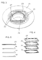
- Nachfolgend wird die Erfindung anhand einer ein Ausführungsbeispiel darstellenden Zeichnung näher erläutert. Es zeigen:
- Fig. 1
- eine perspektivische Ansicht einer erfindungsgemäßen Ablaufvorrichtung;
- Fig. 2
- eine Schnittdarstellung der Ablaufvorrichtung der Fig. 1 in perspektivischer Ansicht;
- Fig. 3
- eine perspektivische Ansicht eines ringscheibenförmigen Elements mit exzentrisch angeordneter Durchbrechung, mehreren darauf aufgelegten Unterlegscheiben und einem den Rost aufnehmenden Rahmen für eine erfindungsgemäße Ablaufvorrichtung; und
- Fig. 4
- eine perspektivische Ansicht der Unterlegscheiben und des den Rost aufnehmenden Rahmens in Explosionsdarstellung;
- Fig. 5
- eine Seitenansicht der Unterlegscheiben und des Rahmens der Fig. 4 in Explosionsdarstellung.
- Die in der Zeichnung dargestellte Ablaufvorrichtung 1 ist insbesondere zur Herstellung einer bodengleichen Dusche bestimmt. Der mit einem Geruchsverschluss 2 versehene Ablauf 3 ist in einem zweiteiligen, kastenförmigen Gehäuse 4 angeordnet. Das Gehäuse 4 der Ablaufvorrichtung 1 ist aus einem Gehäuseunterteil 4.1 und einem eine Ablauföffnung 5 aufweisenden Gehäuseoberteil 4.2 aufgebaut und ermöglicht somit eine Höhenverstellung zum Anpassen an die Bodenkonstruktion.
- Das Gehäuseunterteil 4.1 ist schalenförmig ausgebildet und weist einen Boden 6 und vier im wesentlichen rechtwinklig zueinander ausgerichtete Wände auf, wobei das deckelartige, ebenfalls schalenförmig ausgebildete Gehäuseoberteil 4.2 randseitig das Gehäuseunterteil 4.1 umschließt. Die mit 7 bezeichnete Wand des Gehäuseunterteils 4.1 weist eine Aussparung 8 zur Durchleitung eines Ablaufstutzens 9 auf. In der das Gehäuseunterteil 4.1 umschließenden Wand des Gehäuseoberteils 4.2 ist ebenfalls eine Aussparung 10 vorgesehen. Beide Aussparungen 8 und 10 sind im Wesentlichen U-förmig ausgebildet und reichen bis zur Oberkante des Gehäuseunterteils 4.1 bzw. bis zur Unterkante des Gehäuseoberteils 4.2.
- Die gegenüberliegenden Wände 7 und 11 des Gehäuseunterteils 4.1 sind mit Gewindebohrungen versehen, in die Feststellschrauben 12 eingedreht sind, welche vertikal verlaufende Schlitze 13 in den gegenüberliegenden Wänden des Gehäuseoberteils 4.2 durchgreifen. Zwischen den einander zugewandten Wänden der beiden Gehäuseteile 4.1 und 4.2 sind Körperschall-Dämpfungsmittel 14 angeordnet. Die Körperschall-Dämpfungsmittel 14 können beispielsweise aus an der Innenseite der Wände des Gehäuseoberteils angeklebten Schaumstoffstreifen, insbesondere aus Moosgummistreifen bestehen.
- Das Gehäuseunterteil 4.1 und das Gehäuseoberteil 4.2 bestehen vorzugsweise aus Kunststoff, beispielsweise aus faserverstärktem Polypropylen, Acrylnitril-Butadien-Styrol (ABS) oder anderen Materialien.
- An die Außenseite des Gehäuseunterteils 4.1 sind in der Ebene des Bodens 6 Befestigungslöcher aufweisende Laschen 15 angeformt, während an die Außenseite des Gehäuseoberteils 4.2 mehrere Verankerungsmittel 16 angeformt sind. Die verankerungsmittel 16 dienen dazu, eine stabile Verbindung des Gehäuse zum umgebenden Estrich herzustellen. Die Verankerungsmittel 16 verstärken zudem das Gehäuseoberteil 4.2 und sind in diesem Ausführungsbeispiel in Form gewellter Rippen ausgebildet.
- Die Oberseite des Gehäuseoberteils 4.2 weist eine rasterförmige Struktur 17 auf, die aus gitterartig verlaufenden Rillen 18 bzw. flachen, rechteckigen Erhebungen 19 besteht. An die Unterseite des deckelartigen Gehäuseoberteils 4.2 sind Verstärkungsstege 20 angeformt.
- Der in dem kastenförmigen Gehäuse 4 befindliche Ablauf 3 weist einen Geruchsverschluss 2 auf, der aus einem topfförmigen Kunststoffteil 2.1 gebildet ist, in den ein stutzenförmiger Trennkanal 2.2 ragt, dessen Unterkante eine Umlenkung definiert und zum Boden des topfförmigen Kunststoffteil 2.1 beabstandet ist. Im Boden des topfförmigen Kunststoffteil 2.1 ist eine glockenförmige Erhebung 2.3 ausgebildet, die in den Trennkanal 2.2 ragt. Das topfförmige Kunststoffteil 2.1 weist eine umlaufende Überlaufkante 2.4 auf, die nach außen betrachtet in einen ringförmigen Überlaufkanal 2.5 übergeht, welcher seinerseits in einen stutzenförmigen Abschnitt 2.6 übergeht. Der ringförmige Überlaufkanal 2.5 ist in Richtung des stutzenförmigen Abschnitts 2.6 mit Gefälle ausgebildet.
- Der Geruchsverschluss 2 weist ferner ein ringförmiges Deckelteil 2.7 auf, das den ringförmigen Überlaufkanal 2.5 flüssigkeitsdicht abdeckt und an seiner Durchbrechung 2.8 flüssigkeitsdicht mit dem in das topfförmige Kunststoffteil 2.1 ragenden Trennkanal 2.2 verbunden ist.
- Der stutzenförmige Abschnitt 2.6 des Ablaufs bzw. Geruchsverschlusses weist eine kugelförmige Verdickung auf, die zusammen mit einem Rohrstück 21 ein Kugelgelenk bildet. Das Rohrstück 21 weist ebenfalls eine kugelförmige Verdickung auf, die mit dem aus dem kastenförmigen Gehäuse 4 herausragenden Ablaufstutzen 9 ein Kugelgelenk bildet. In Fig. 2 ist zu erkennen, dass in den kugelförmigen Verdickungen Ringnuten 22, 23 ausgebildet sind, die der Aufnahme von Dichtungsringen (in Fig.2 nicht gezeigt) dienen.
- Der im kastenförmigen Gehäuse 4 angeordnete, mit dem Geruchsverschluss 2 versehene Ablauf 3 ist eine in Bezug auf das Gehäuse 4 separat gefertigte Komponente der erfindungsgemäßen Ablaufvorrrichtung.
- Das Gehäuseoberteil 4.2 weist oberseitig eine kreisringförmige, die Ablauföffnung 5 umgebende Vertiefung 24 auf. In der Vertiefung ist ein ringscheibenförmiges Element 25 drehbar aufgenommen, das eine exzentrisch angeordnete Durchbrechung 26 aufweist. In der Oberseite des ringscheibenförmigen Elements 25 ist eine flache, im wesentlichen ebene Vertiefung 27 ausgebildet, in welcher ein Rost 28 im wesentlichen horizontal verschiebbar angeordnet ist. Die Vertiefung 27 hat eine im wesentlichen rechteckige, vorzugsweise quadratische Form, die größer ist als ein den Rost 28 aufnehmender Rahmen 29. Die Verschiebung des Rostes 28 ist in der Ebene der Vertiefung 27 in mindestens zwei quer zueinander verlaufenden Richtungen möglich.
- Der vorzugsweise aus Edelstahl hergestellte Rost 28 ist in einem Rahmen 29 aufgenommen, der aus Kunststoff oder Edelstahl besteht. Der Rahmen 29 ist mit mehreren rahmenförmigen Unterlegscheiben 30, 31, 32 versehen, die eine unterschiedliche Dicke aufweisen. Die Unterlegscheiben 30, 31, 32 sind untereinander und mit dem den Rost 28 aufnehmenden Rahmen 29 verrastbar oder formschlüssig verbindbar.
- Das tellerförmige, ringscheibenförmige Element 25 besitzt oberseitig eine Vielzahl von Rillen oder Nuten 33, die an der Durchbrechung 26 münden. Ausgehend von der Durchbrechung 26 erstrecken sich die Nuten 33 im wesentlichen radial und enden mit Abstand vor dem äußeren Rand des ringscheibenförmigen Elements 25. Die Nuten 33 weisen vorzugsweise jeweils einen in Richtung der Durchbrechung 26 geneigten Nutgrund auf.
- Zu ihrer Montage wird die kastenförmige Ablaufvorrichtung 1 auf den Rohboden der Dusche gestellt und an den Laschen 15 festgeschraubt. Danach wird Höhe des kastenförmigen Gehäuses 4 so eingestellt und mit dem seitlichen Feststellschrauben 12 fixiert, dass die Oberkante (Oberseite) des deckelartigen Gehäuseoberteils 4.2 der Höhe (Oberkante) des einzubringenden Estrichs entspricht. Anschließend wird der sich im kastenförmigen Gehäuse 4 befindliche Ablauf 3 über den Ablaufstutzen 9 mit einer Entwässerungsleitung verbunden. Die rippenförmigen Verankerungsmittel 16, welche in den Estrich eingreifen, sorgen für Stabilität und eine gute Verankerung des Gehäuses 4 im Estrich.
- Sollte sich bei der Verlegung des Estrichs ergeben, dass das kastenförmige Gehäuse 4 in einer falschen Höhe positioniert ist, kann das Gehäuse 4 noch nachträglich durch das zwischen dem Geruchsverschluss 2 und dem Ablaufstutzen 9 angeordnete Doppelkugelgelenk in der Höhe korrigiert werden, und zwar sowohl nach unten als auch nach oben, beispielsweise um etwa ± 20 mm.
- Die nächsten Arbeitsschritte führt der Fliesenleger durch. Nach Entfernen einer Bauschutzfolie wird der Fußboden und die Oberfläche des Gehäuseoberteiles 4.2 mit einer sogenannten Flüssigfolie bestrichen. In diese Folie wird eine Sicherheits-Dichtmanschette gelegt und ebenfalls mit Flüssigfolie bestrichen. Nun ist der Übergang von dem Duschablaufgehäuse 4 zum Estrich sicher abgedichtet. Als letztes kann der Rost 28 mit Hilfe des exzentrischen Ringelements 25 bis zu etwa 15 mm aus der Mitte heraus seitenverstellt werden. Somit ist es auch im Nachhinein noch möglich, den Rost 28 bzw. den ihn tragenden Rahmen 29 ins Fliesenraster einzupassen.
- Damit der Rost 28 auch an unterschiedliche Fliesen- bzw. Natursteinstärken angepasst werden kann, wird mit bis zu drei verschiedenen Unterlegscheiben 30, 31, 32, die eine Dicke von z.B. 3 mm, 5 mm bzw. 7 mm aufweisen und unter den Rahmen 29 gelegt werden, eine Höhenverstellung vorgenommen. Nach der Verfliesung des Bodens und der Oberseite des Gehäuses 4 und der abschließenden Verfugung (einschließlich der üblichen Silikonabdichtung) ist die bodengleiche Dusche fertig.
- Sollte die um den Rahmen üblicherweise angebrachte Silikonfuge später eventuell reißen, läuft das dort eindringende Sickerwasser durch die Rillen oder Nuten 33 des scheibenförmigen Ringelements 25 direkt in den Ablauf 3, sodass eine Anstauung von Wasser, welches nach einiger Zeit einem Faulprozess unterworfen ist, ausgeschlossen ist.
- Die Erfindung ist in ihrer Ausführung nicht auf das vorstehend beschriebene Ausführungsbeispiel beschränkt. Vielmehr sind eine Reihe von Varianten möglich, die auch bei abweichender Gestaltung von dem in den beigefügten Ansprüchen enthaltenen Erfindungsgedanken Gebrauch machen. So liegt es beispielsweise auch im Rahmen der Erfindung, anstelle von seitlichen Feststellschrauben 12 Einstellschrauben in dem Gehäuseoberteil anzubringen, die über in der Oberseite des Gehäuseoberteils 4.2 ausgebildete Durchbrechungen (nicht gezeigt), welche gegebenenfalls mit zugeordneten Kappen oder der gleichen verschließbar sind, mittels eines Schraubendrehers zugänglich und verstellbar sind.
Claims (13)
- Ablaufvorrichtung (1) zur Herstellung eines in einem Boden eingebetteten Wasserablaufs, insbesondere zur Herstellung einer bodengleiche Dusche, mit einem Rost (28), einem eine Ablauföffnung (5) aufweisenden und den Rost tragenden Gehäuse (4), einem Geruchsverschluss (2) und einem mit einer Entwässerungsleitung lösbar verbindbaren Ablaufstutzen (9),
dadurch gekennzeichnet, dass
das Gehäuse (4) in Form eines kastenförmigen Gehäuses aus einem schalenförmigen Gehäuseunterteil (4.1) und einem deckelartigen Gehäuseoberteil (4.2) aufgebaut ist, wobei der Geruchsverschluss (2) in seiner Lage relativ zu dem Gehäuseoberteil (4.2) und/oder dem Gehäuseunterteil (4.1) verstellbar in dem Gehäuse (4) angeordnet ist, und wobei das Gehäuseoberteil (4.2) höhenverstellbar gegenüber dem Gehäuseunterteil (4.1) mit demselben verbunden ist und Verankerungsmittel (16) aufweist, die der Verankerung des Gehäuseoberteils (4.2) in einem Estrich dienen. - Ablaufvorrichtung nach Anspruch 1,
dadurch gekennzeichnet, dass das Gehäuseoberteil (4.2) randseitig das Gehäuseunterteil (4.1) umschließt. - Ablaufvorrichtung nach Anspruch 1 oder 2,
dadurch gekennzeichnet, dass die Höhe des Gehäuseoberteils (4.2) gegenüber dem Gehäuseunterteil (4.1) mittels am Gehäuseoberteil (4.2) und/oder am Gehäuseunterteil (4.1) befestigter Schrauben (12) einstellbar und/oder feststellbar ist. - Ablaufvorrichtung nach einem der Ansprüche 1 bis 3,
dadurch gekennzeichnet, dass das Gehäuseunterteil (4.1) mit Befestigungslaschen (15) versehen ist. - Ablaufvorrichtung nach einem der Ansprüche 1 bis 4,
dadurch gekennzeichnet, dass die Verankerungsmittel (16) in Form von gewellten Rippen ausgebildet sind. - Ablaufvorrichtung nach einem der Ansprüche 1 bis 5,
dadurch gekennzeichnet, dass zwischen dem Geruchsverschluss (2) und dem Ablaufstutzen (9) ein Rohrstück (21) angeordnet ist, das sowohl mit dem Geruchsverschluss (2) als auch mit dem Ablaufstutzen (9) gelenkig und flüssigkeitsdicht verbunden ist. - Ablaufvorrichtung nach einem der Ansprüche 1 bis 6,
dadurch gekennzeichnet, dass zwischen dem Gehäuseunterteil (4.1) und dem Gehäuseoberteil (4.2) Körperschall-Dämpfungsmittel (14) angeordnet sind. - Ablaufvorrichtung nach einem der Ansprüche 1 bis 7,
dadurch gekennzeichnet, dass das Gehäuseoberteil (4.2) oberseitig eine kreisringförmige, die Ablauföffnung (5) umgebende Vertiefung (24) aufweist, in der ein ringscheibenförmiges, eine exzentrisch angeordnete Durchbrechung (26) aufweisendes Element (25) drehbar aufgenommen ist, wobei das ringscheibenförmige Element (25) oberseitig eine Vertiefung (27) aufweist, in welcher der Rost (28) im wesentlichen horizontal verschiebbar angeordnet ist. - Ablaufvorrichtung nach Anspruch 8,
dadurch gekennzeichnet, dass das ringscheibenförmige Element (25) oberseitig mit einer Vielzahl von Nuten (33) versehen ist, die an der Durchbrechung (26) münden. - Ablaufvorrichtung nach Anspruch 9,
dadurch gekennzeichnet, dass die Nuten (33) sich ausgehend von der Durchbrechung (26) des ringscheibenförmige Element (25) im wesentlichen in radialer Richtung erstrecken und einen in Richtung der Durchbrechung (26) geneigten Nutgrund aufweisen. - Ablaufvorrichtung nach einem der Ansprüche 1 bis 10,
dadurch gekennzeichnet, dass dem Rost (28) oder einem den Rost aufnehmenden Rahmen (29) eine oder mehrere rahmenförmige Unterlegscheiben (30, 31, 32) zugeordnet sind. - Ablaufvorrichtung nach Anspruch 11,
dadurch gekennzeichnet, dass die Unterlegscheiben (30, 31, 32) eine unterschiedliche Dicke aufweisen. - Ablaufvorrichtung nach Anspruch 11 oder 12,
dadurch gekennzeichnet, dass die Unterlegscheibe (30) mit einem den Rost (28) aufnehmenden Rahmen (29) und/oder einer anderen Unterlegscheibe (31, 32) verrastbar oder formschlüssig verbindbar ist.
Priority Applications (1)
| Application Number | Priority Date | Filing Date | Title |
|---|---|---|---|
| PL06123934T PL1785534T3 (pl) | 2005-11-15 | 2006-11-13 | Urządzenie odpływowe do natrysku bezbrodzikowego/z brodzikiem posadzkowym |
Applications Claiming Priority (1)
| Application Number | Priority Date | Filing Date | Title |
|---|---|---|---|
| DE202005017965U DE202005017965U1 (de) | 2005-11-15 | 2005-11-15 | Ablaufvorrichtung für eine bodengleiche Dusche |
Publications (2)
| Publication Number | Publication Date |
|---|---|
| EP1785534A1 true EP1785534A1 (de) | 2007-05-16 |
| EP1785534B1 EP1785534B1 (de) | 2011-01-05 |
Family
ID=37798427
Family Applications (1)
| Application Number | Title | Priority Date | Filing Date |
|---|---|---|---|
| EP06123934A Active EP1785534B1 (de) | 2005-11-15 | 2006-11-13 | Ablaufvorrichtung für eine bodengleiche Dusche |
Country Status (6)
| Country | Link |
|---|---|
| EP (1) | EP1785534B1 (de) |
| AT (1) | ATE494431T1 (de) |
| DE (2) | DE202005017965U1 (de) |
| DK (1) | DK1785534T3 (de) |
| ES (1) | ES2356676T3 (de) |
| PL (1) | PL1785534T3 (de) |
Cited By (2)
| Publication number | Priority date | Publication date | Assignee | Title |
|---|---|---|---|---|
| GB2483660A (en) * | 2010-09-15 | 2012-03-21 | Alexander Charles Hodgetts | Shower floor installation |
| US9545178B2 (en) | 2013-03-15 | 2017-01-17 | Fin-Pan, Inc. | Shower floor |
Families Citing this family (18)
| Publication number | Priority date | Publication date | Assignee | Title |
|---|---|---|---|---|
| DE202008011197U1 (de) | 2008-08-22 | 2009-12-31 | Viega Gmbh & Co. Kg | Ablaufarmatur mit Geruchverschluss |
| DE202008011272U1 (de) | 2008-08-25 | 2010-02-11 | Viega Gmbh & Co. Kg | Ablauf, insbesondere für bodengleiche Duschen |
| DE102008052285B4 (de) * | 2008-10-18 | 2014-01-30 | Dallmer Gmbh & Co. Kg | Ablaufvorrichtung |
| EP2305905B1 (de) | 2009-09-24 | 2012-10-31 | VIEGA GmbH & Co. KG | Bodenablauf mit veränderbarer Einbauhöhe |
| DE202009012826U1 (de) | 2009-09-24 | 2011-02-10 | Viega Gmbh & Co. Kg | Ablauf, insbesondere für bodengleiche Duschen |
| CH703597B1 (de) * | 2010-09-01 | 2012-04-30 | Urs Gassmann | Mehrzweck-Siphon. |
| DE102010046179A1 (de) * | 2010-09-23 | 2012-03-29 | Stephan Wedi | Abwasserablauf mit Geruchsverschluss, insbesondere als Ablauf für Duschwannen |
| DE202011109947U1 (de) * | 2011-01-21 | 2012-08-01 | Franz Kaldewei Gmbh & Co. Kg | Sanitärwanne |
| DE102011107817A1 (de) | 2011-07-01 | 2013-01-03 | Hans-Georg Scholz | Einrichtung zum Abpumpen von Flüssigkeiten |
| CH706562B1 (de) * | 2012-05-28 | 2017-12-15 | Gassmann Urs | Siphon mit integrierter Reinigungsfunktion. |
| PL2818601T3 (pl) * | 2013-06-26 | 2018-03-30 | Geberit International Ag | Ustawny dopływ dla odpływu podłogowego |
| DE202015105639U1 (de) * | 2015-10-23 | 2017-01-24 | Werner Schlüter | Bodenablauf mit Geruchsverschluss |
| DE202021101723U1 (de) | 2021-03-31 | 2022-07-07 | Viega Technology Gmbh & Co. Kg | Bodenablauf mit höhenverstellbarem Geruchverschluss |
| DE202021101724U1 (de) | 2021-03-31 | 2022-07-07 | Viega Technology Gmbh & Co. Kg | Ablaufvorrichtung zur Herstellung eines in einem Boden eingebetteten Wasserablaufs |
| DE102022105975A1 (de) * | 2022-03-15 | 2023-09-21 | Franz Kaldewei Gmbh & Co. Kg | Bodenablauf und Bodeninstallation |
| EP4283060B1 (de) | 2022-05-25 | 2024-12-25 | EDM-System GmbH | Verlegekasten zur aufnahme einer ablaufgarnitur |
| DE202022102917U1 (de) | 2022-05-25 | 2022-08-16 | EDM-System GmbH | Verlegekasten zur Aufnahme einer Ablaufgarnitur und Justierrahmen für einen Verlegekasten |
| EP4283059B1 (de) * | 2022-05-25 | 2025-04-16 | EDM-System GmbH | Verlegekasten zur aufnahme einer ablaufgarnitur |
Citations (4)
| Publication number | Priority date | Publication date | Assignee | Title |
|---|---|---|---|---|
| EP0457011A1 (de) * | 1990-04-28 | 1991-11-21 | FIRMA DALLMER GmbH & Co. | Ablauf für einen Fliesenfussboden |
| CH682827A5 (de) * | 1991-03-21 | 1993-11-30 | Besgo Schwimmbad Technik | Arretierung für ein Oberteil eines Bodenablaufs oder Schlammfängers. |
| EP1253254A2 (de) * | 2001-04-25 | 2002-10-30 | Beldore Limited | Siphon mit Pumpe und dazugehöriges Installationsverfahren |
| DE202005012802U1 (de) * | 2005-08-11 | 2005-11-10 | Sanitärtechnik Eisenberg GmbH | Sanitärablaufsystem |
Family Cites Families (11)
| Publication number | Priority date | Publication date | Assignee | Title |
|---|---|---|---|---|
| DE3020634C2 (de) * | 1980-05-30 | 1985-01-31 | Passavant-Werke AG & Co KG, 6209 Aarbergen | Ablauf mit Geruchverschluß |
| DE3819173C2 (de) * | 1988-06-04 | 1997-09-25 | Emil Grumbach | Wassereinlauf für Gründächer, Gründecken oder Grünflächen über Tiefgaragen |
| DE4206512C2 (de) * | 1992-03-02 | 1994-10-06 | Bernhard Kessel | Boden- oder Terrassenablauf |
| DE19711602C2 (de) * | 1997-03-20 | 2003-12-24 | Dallmer Gmbh & Co Kg | Ablauf mit höhenverstellbarem Einlaufteil |
| AUPP150798A0 (en) * | 1998-01-28 | 1998-02-19 | Reed, Selwyn T. | Smart waste |
| FR2800260B1 (fr) * | 1999-11-03 | 2002-04-12 | Wirquin Plastiques Sa | Installation sanitaire et dispositif de vidande pour une telle installation |
| DE10112546C2 (de) * | 2001-03-15 | 2003-08-07 | Ahlmann Aco Severin | Entwässerungseinrichtung sowie Verfahren zur Herstellung einer Entwässerungsanordnung |
| DE10306120A1 (de) * | 2001-09-20 | 2004-08-26 | Mehdi Ghetmiri | Bodenbündiger Duschplatz |
| DE10201345B4 (de) * | 2002-01-16 | 2016-07-28 | Dallmer Gmbh & Co. Kg | Ablaufeinheit für den Einbau in den Boden eines Raumes |
| DE10360310A1 (de) * | 2003-12-18 | 2005-07-21 | Dallmer Gmbh & Co. Kg | Ablaufvorrichtung |
| DE102004011853A1 (de) * | 2004-02-03 | 2005-08-18 | Dallmer Gmbh & Co. Kg | Ablaufvorrichtung für eine Dusche oder dergleichen |
-
2005
- 2005-11-15 DE DE202005017965U patent/DE202005017965U1/de not_active Expired - Lifetime
-
2006
- 2006-11-13 AT AT06123934T patent/ATE494431T1/de active
- 2006-11-13 PL PL06123934T patent/PL1785534T3/pl unknown
- 2006-11-13 EP EP06123934A patent/EP1785534B1/de active Active
- 2006-11-13 DE DE502006008651T patent/DE502006008651D1/de active Active
- 2006-11-13 DK DK06123934.9T patent/DK1785534T3/da active
- 2006-11-13 ES ES06123934T patent/ES2356676T3/es active Active
Patent Citations (4)
| Publication number | Priority date | Publication date | Assignee | Title |
|---|---|---|---|---|
| EP0457011A1 (de) * | 1990-04-28 | 1991-11-21 | FIRMA DALLMER GmbH & Co. | Ablauf für einen Fliesenfussboden |
| CH682827A5 (de) * | 1991-03-21 | 1993-11-30 | Besgo Schwimmbad Technik | Arretierung für ein Oberteil eines Bodenablaufs oder Schlammfängers. |
| EP1253254A2 (de) * | 2001-04-25 | 2002-10-30 | Beldore Limited | Siphon mit Pumpe und dazugehöriges Installationsverfahren |
| DE202005012802U1 (de) * | 2005-08-11 | 2005-11-10 | Sanitärtechnik Eisenberg GmbH | Sanitärablaufsystem |
Cited By (2)
| Publication number | Priority date | Publication date | Assignee | Title |
|---|---|---|---|---|
| GB2483660A (en) * | 2010-09-15 | 2012-03-21 | Alexander Charles Hodgetts | Shower floor installation |
| US9545178B2 (en) | 2013-03-15 | 2017-01-17 | Fin-Pan, Inc. | Shower floor |
Also Published As
| Publication number | Publication date |
|---|---|
| PL1785534T3 (pl) | 2011-06-30 |
| DK1785534T3 (da) | 2011-04-11 |
| ATE494431T1 (de) | 2011-01-15 |
| EP1785534B1 (de) | 2011-01-05 |
| DE502006008651D1 (de) | 2011-02-17 |
| DE202005017965U1 (de) | 2007-03-29 |
| ES2356676T3 (es) | 2011-04-12 |
Similar Documents
| Publication | Publication Date | Title |
|---|---|---|
| EP1785534B1 (de) | Ablaufvorrichtung für eine bodengleiche Dusche | |
| DE60115636T2 (de) | Ein ablauf und eine gebäudestruktur mit einem ablauf | |
| EP3031990B1 (de) | Bodenablauf | |
| EP2333171B1 (de) | Bodenablauf für eine sanitäre Installation und Verfahren zum Montieren eines solchen Bodenablaufs | |
| DE202006002077U1 (de) | Ablaufrinne und System zur Bildung eines Wasserablaufs, vorzugsweise für bodengleiche Duschen | |
| EP2756137B1 (de) | Ablaufrinne für eine bodengleiche dusche | |
| EP2067902B1 (de) | Verfahren zum Einbau eines Ablaufs in einen Unterlagsboden, Ablauf mit einer Ablaufwanne sowie Gebäudeboden mit einem solchen Ablauf | |
| EP4283059B1 (de) | Verlegekasten zur aufnahme einer ablaufgarnitur | |
| EP1210897B1 (de) | Duschtasse | |
| DE102011119705A1 (de) | Ablaufeinheit | |
| DE102007058299B4 (de) | Einbauverfahren für den Einbau einer bodenebenen Ablaufrinne in einem Boden und Einbausatz zur Durchführung des Verfahrens | |
| DE102004049130A1 (de) | Duschwanne mit auf einem höhenverstellbaren Duschwannenträger aufsetzbarer Duschwannenschale | |
| EP3357384B1 (de) | Boden einer dusche | |
| DE102012105555B4 (de) | Aufnahmeeinheit zur Aufnahme einer Wiegeeinheit und Anordnung zur Ermittlung einer Masse | |
| DE102006051130B4 (de) | Ablaufvorrichtung für die zumindest teilweise Einbringung in einen Boden eines Raumes | |
| EP1783285B1 (de) | Verstellbarer Aufsatz für sanitären Bodenablauf | |
| DE202009017155U1 (de) | Bodenablauf für eine sanitäre Installation | |
| EP4173531A1 (de) | Bodenebene duschtasse | |
| DE10112546C2 (de) | Entwässerungseinrichtung sowie Verfahren zur Herstellung einer Entwässerungsanordnung | |
| AT9592U1 (de) | Einlaufeinrichtung für einen bodenablauf und bodenablauf | |
| EP2995733B1 (de) | Wandablaufrinne für eine dusche | |
| DE202005018839U1 (de) | Aufsatz für einen sanitären Bodenablauf, insbesondere für einen Bodenablauf einer bodengleichen Dusche | |
| DE10210496C1 (de) | Vorrichtung zur Positionierung eines Siphons | |
| DE102017203122B4 (de) | Anordnung mit einer Überlaufrinne für einen Türbereich eines Nassraums | |
| DE3501821A1 (de) | Bodenablauf |
Legal Events
| Date | Code | Title | Description |
|---|---|---|---|
| PUAI | Public reference made under article 153(3) epc to a published international application that has entered the european phase |
Free format text: ORIGINAL CODE: 0009012 |
|
| AK | Designated contracting states |
Kind code of ref document: A1 Designated state(s): AT BE BG CH CY CZ DE DK EE ES FI FR GB GR HU IE IS IT LI LT LU LV MC NL PL PT RO SE SI SK TR |
|
| AX | Request for extension of the european patent |
Extension state: AL BA HR MK YU |
|
| 17P | Request for examination filed |
Effective date: 20070514 |
|
| 17Q | First examination report despatched |
Effective date: 20070622 |
|
| AKX | Designation fees paid |
Designated state(s): AT BE BG CH CY CZ DE DK EE ES FI FR GB GR HU IE IS IT LI LT LU LV MC NL PL PT RO SE SI SK TR |
|
| GRAP | Despatch of communication of intention to grant a patent |
Free format text: ORIGINAL CODE: EPIDOSNIGR1 |
|
| GRAS | Grant fee paid |
Free format text: ORIGINAL CODE: EPIDOSNIGR3 |
|
| GRAA | (expected) grant |
Free format text: ORIGINAL CODE: 0009210 |
|
| AK | Designated contracting states |
Kind code of ref document: B1 Designated state(s): AT BE BG CH CY CZ DE DK EE ES FI FR GB GR HU IE IS IT LI LT LU LV MC NL PL PT RO SE SI SK TR |
|
| REG | Reference to a national code |
Ref country code: GB Ref legal event code: FG4D Free format text: NOT ENGLISH |
|
| REG | Reference to a national code |
Ref country code: CH Ref legal event code: EP |
|
| REG | Reference to a national code |
Ref country code: CH Ref legal event code: NV Representative=s name: TROESCH SCHEIDEGGER WERNER AG |
|
| REG | Reference to a national code |
Ref country code: IE Ref legal event code: FG4D Free format text: LANGUAGE OF EP DOCUMENT: GERMAN |
|
| REF | Corresponds to: |
Ref document number: 502006008651 Country of ref document: DE Date of ref document: 20110217 Kind code of ref document: P |
|
| REG | Reference to a national code |
Ref country code: DE Ref legal event code: R096 Ref document number: 502006008651 Country of ref document: DE Effective date: 20110217 |
|
| REG | Reference to a national code |
Ref country code: SE Ref legal event code: TRGR |
|
| REG | Reference to a national code |
Ref country code: NL Ref legal event code: T3 |
|
| REG | Reference to a national code |
Ref country code: DK Ref legal event code: T3 |
|
| REG | Reference to a national code |
Ref country code: ES Ref legal event code: FG2A Ref document number: 2356676 Country of ref document: ES Kind code of ref document: T3 Effective date: 20110412 |
|
| PG25 | Lapsed in a contracting state [announced via postgrant information from national office to epo] |
Ref country code: SI Free format text: LAPSE BECAUSE OF FAILURE TO SUBMIT A TRANSLATION OF THE DESCRIPTION OR TO PAY THE FEE WITHIN THE PRESCRIBED TIME-LIMIT Effective date: 20110105 |
|
| LTIE | Lt: invalidation of european patent or patent extension |
Effective date: 20110105 |
|
| REG | Reference to a national code |
Ref country code: PL Ref legal event code: T3 |
|
| PG25 | Lapsed in a contracting state [announced via postgrant information from national office to epo] |
Ref country code: LV Free format text: LAPSE BECAUSE OF FAILURE TO SUBMIT A TRANSLATION OF THE DESCRIPTION OR TO PAY THE FEE WITHIN THE PRESCRIBED TIME-LIMIT Effective date: 20110105 Ref country code: IS Free format text: LAPSE BECAUSE OF FAILURE TO SUBMIT A TRANSLATION OF THE DESCRIPTION OR TO PAY THE FEE WITHIN THE PRESCRIBED TIME-LIMIT Effective date: 20110505 Ref country code: GR Free format text: LAPSE BECAUSE OF FAILURE TO SUBMIT A TRANSLATION OF THE DESCRIPTION OR TO PAY THE FEE WITHIN THE PRESCRIBED TIME-LIMIT Effective date: 20110406 Ref country code: LT Free format text: LAPSE BECAUSE OF FAILURE TO SUBMIT A TRANSLATION OF THE DESCRIPTION OR TO PAY THE FEE WITHIN THE PRESCRIBED TIME-LIMIT Effective date: 20110105 Ref country code: PT Free format text: LAPSE BECAUSE OF FAILURE TO SUBMIT A TRANSLATION OF THE DESCRIPTION OR TO PAY THE FEE WITHIN THE PRESCRIBED TIME-LIMIT Effective date: 20110505 |
|
| REG | Reference to a national code |
Ref country code: IE Ref legal event code: FD4D |
|
| PG25 | Lapsed in a contracting state [announced via postgrant information from national office to epo] |
Ref country code: FI Free format text: LAPSE BECAUSE OF FAILURE TO SUBMIT A TRANSLATION OF THE DESCRIPTION OR TO PAY THE FEE WITHIN THE PRESCRIBED TIME-LIMIT Effective date: 20110105 Ref country code: CY Free format text: LAPSE BECAUSE OF FAILURE TO SUBMIT A TRANSLATION OF THE DESCRIPTION OR TO PAY THE FEE WITHIN THE PRESCRIBED TIME-LIMIT Effective date: 20110105 Ref country code: BG Free format text: LAPSE BECAUSE OF FAILURE TO SUBMIT A TRANSLATION OF THE DESCRIPTION OR TO PAY THE FEE WITHIN THE PRESCRIBED TIME-LIMIT Effective date: 20110405 |
|
| PG25 | Lapsed in a contracting state [announced via postgrant information from national office to epo] |
Ref country code: EE Free format text: LAPSE BECAUSE OF FAILURE TO SUBMIT A TRANSLATION OF THE DESCRIPTION OR TO PAY THE FEE WITHIN THE PRESCRIBED TIME-LIMIT Effective date: 20110105 Ref country code: IE Free format text: LAPSE BECAUSE OF FAILURE TO SUBMIT A TRANSLATION OF THE DESCRIPTION OR TO PAY THE FEE WITHIN THE PRESCRIBED TIME-LIMIT Effective date: 20110105 |
|
| PLBE | No opposition filed within time limit |
Free format text: ORIGINAL CODE: 0009261 |
|
| STAA | Information on the status of an ep patent application or granted ep patent |
Free format text: STATUS: NO OPPOSITION FILED WITHIN TIME LIMIT |
|
| PG25 | Lapsed in a contracting state [announced via postgrant information from national office to epo] |
Ref country code: SK Free format text: LAPSE BECAUSE OF FAILURE TO SUBMIT A TRANSLATION OF THE DESCRIPTION OR TO PAY THE FEE WITHIN THE PRESCRIBED TIME-LIMIT Effective date: 20110105 Ref country code: RO Free format text: LAPSE BECAUSE OF FAILURE TO SUBMIT A TRANSLATION OF THE DESCRIPTION OR TO PAY THE FEE WITHIN THE PRESCRIBED TIME-LIMIT Effective date: 20110105 Ref country code: CZ Free format text: LAPSE BECAUSE OF FAILURE TO SUBMIT A TRANSLATION OF THE DESCRIPTION OR TO PAY THE FEE WITHIN THE PRESCRIBED TIME-LIMIT Effective date: 20110105 |
|
| 26N | No opposition filed |
Effective date: 20111006 |
|
| REG | Reference to a national code |
Ref country code: DE Ref legal event code: R097 Ref document number: 502006008651 Country of ref document: DE Effective date: 20111006 |
|
| PG25 | Lapsed in a contracting state [announced via postgrant information from national office to epo] |
Ref country code: MC Free format text: LAPSE BECAUSE OF NON-PAYMENT OF DUE FEES Effective date: 20111130 |
|
| GBPC | Gb: european patent ceased through non-payment of renewal fee |
Effective date: 20111113 |
|
| PG25 | Lapsed in a contracting state [announced via postgrant information from national office to epo] |
Ref country code: GB Free format text: LAPSE BECAUSE OF NON-PAYMENT OF DUE FEES Effective date: 20111113 |
|
| PG25 | Lapsed in a contracting state [announced via postgrant information from national office to epo] |
Ref country code: LU Free format text: LAPSE BECAUSE OF NON-PAYMENT OF DUE FEES Effective date: 20111113 |
|
| PG25 | Lapsed in a contracting state [announced via postgrant information from national office to epo] |
Ref country code: TR Free format text: LAPSE BECAUSE OF FAILURE TO SUBMIT A TRANSLATION OF THE DESCRIPTION OR TO PAY THE FEE WITHIN THE PRESCRIBED TIME-LIMIT Effective date: 20110105 |
|
| PG25 | Lapsed in a contracting state [announced via postgrant information from national office to epo] |
Ref country code: HU Free format text: LAPSE BECAUSE OF FAILURE TO SUBMIT A TRANSLATION OF THE DESCRIPTION OR TO PAY THE FEE WITHIN THE PRESCRIBED TIME-LIMIT Effective date: 20110105 |
|
| REG | Reference to a national code |
Ref country code: FR Ref legal event code: PLFP Year of fee payment: 10 |
|
| REG | Reference to a national code |
Ref country code: FR Ref legal event code: PLFP Year of fee payment: 11 |
|
| PG25 | Lapsed in a contracting state [announced via postgrant information from national office to epo] |
Ref country code: BE Free format text: LAPSE BECAUSE OF NON-PAYMENT OF DUE FEES Effective date: 20161130 |
|
| REG | Reference to a national code |
Ref country code: DE Ref legal event code: R082 Ref document number: 502006008651 Country of ref document: DE Representative=s name: COHAUSZ & FLORACK PATENT- UND RECHTSANWAELTE P, DE Ref country code: DE Ref legal event code: R081 Ref document number: 502006008651 Country of ref document: DE Owner name: VIEGA TECHNOLOGY GMBH & CO. KG, DE Free format text: FORMER OWNER: VIEGA GMBH & CO. KG, 57439 ATTENDORN, DE |
|
| PG25 | Lapsed in a contracting state [announced via postgrant information from national office to epo] |
Ref country code: BE Free format text: LAPSE BECAUSE OF NON-PAYMENT OF DUE FEES Effective date: 20161130 |
|
| PGRI | Patent reinstated in contracting state [announced from national office to epo] |
Ref country code: BE Effective date: 20170112 |
|
| REG | Reference to a national code |
Ref country code: AT Ref legal event code: PC Ref document number: 494431 Country of ref document: AT Kind code of ref document: T Owner name: VIEGA TECHNOLOGY GMBH & CO. KG, DE Effective date: 20170512 |
|
| REG | Reference to a national code |
Ref country code: NL Ref legal event code: PD Owner name: VIEGA TECHNOLOGY GMBH & CO. KG; DE Free format text: DETAILS ASSIGNMENT: CHANGE OF OWNER(S), ASSIGNMENT; FORMER OWNER NAME: VIEGA GMBH & CO. KG Effective date: 20170412 |
|
| REG | Reference to a national code |
Ref country code: FR Ref legal event code: TP Owner name: VIEGA TECHNOLOGY GMBH & CO. KG, DE Effective date: 20171013 |
|
| REG | Reference to a national code |
Ref country code: FR Ref legal event code: PLFP Year of fee payment: 12 |
|
| REG | Reference to a national code |
Ref country code: ES Ref legal event code: PC2A Owner name: VIEGA TECHNOLOGY GMBH & CO. KG Effective date: 20180108 |
|
| REG | Reference to a national code |
Ref country code: CH Ref legal event code: PUE Owner name: VIEGA TECHNOLOGY GMBH AND CO. KG, DE Free format text: FORMER OWNER: VIEGA GMBH AND CO. KG, DE |
|
| PGFP | Annual fee paid to national office [announced via postgrant information from national office to epo] |
Ref country code: SE Payment date: 20211118 Year of fee payment: 16 Ref country code: AT Payment date: 20211119 Year of fee payment: 16 Ref country code: DK Payment date: 20211123 Year of fee payment: 16 Ref country code: ES Payment date: 20211215 Year of fee payment: 16 Ref country code: FR Payment date: 20211118 Year of fee payment: 16 |
|
| PGFP | Annual fee paid to national office [announced via postgrant information from national office to epo] |
Ref country code: IT Payment date: 20211124 Year of fee payment: 16 Ref country code: BE Payment date: 20211118 Year of fee payment: 16 |
|
| PGFP | Annual fee paid to national office [announced via postgrant information from national office to epo] |
Ref country code: PL Payment date: 20211105 Year of fee payment: 16 |
|
| PGFP | Annual fee paid to national office [announced via postgrant information from national office to epo] |
Ref country code: NL Payment date: 20221122 Year of fee payment: 17 |
|
| PGFP | Annual fee paid to national office [announced via postgrant information from national office to epo] |
Ref country code: CH Payment date: 20221123 Year of fee payment: 17 |
|
| REG | Reference to a national code |
Ref country code: DK Ref legal event code: EBP Effective date: 20221130 |
|
| REG | Reference to a national code |
Ref country code: SE Ref legal event code: EUG |
|
| REG | Reference to a national code |
Ref country code: AT Ref legal event code: MM01 Ref document number: 494431 Country of ref document: AT Kind code of ref document: T Effective date: 20221113 |
|
| REG | Reference to a national code |
Ref country code: BE Ref legal event code: MM Effective date: 20221130 |
|
| PG25 | Lapsed in a contracting state [announced via postgrant information from national office to epo] |
Ref country code: AT Free format text: LAPSE BECAUSE OF NON-PAYMENT OF DUE FEES Effective date: 20221113 |
|
| PG25 | Lapsed in a contracting state [announced via postgrant information from national office to epo] |
Ref country code: SE Free format text: LAPSE BECAUSE OF NON-PAYMENT OF DUE FEES Effective date: 20221114 |
|
| PG25 | Lapsed in a contracting state [announced via postgrant information from national office to epo] |
Ref country code: IT Free format text: LAPSE BECAUSE OF NON-PAYMENT OF DUE FEES Effective date: 20221113 Ref country code: DK Free format text: LAPSE BECAUSE OF NON-PAYMENT OF DUE FEES Effective date: 20221130 |
|
| PG25 | Lapsed in a contracting state [announced via postgrant information from national office to epo] |
Ref country code: FR Free format text: LAPSE BECAUSE OF NON-PAYMENT OF DUE FEES Effective date: 20221130 Ref country code: BE Free format text: LAPSE BECAUSE OF NON-PAYMENT OF DUE FEES Effective date: 20221130 |
|
| REG | Reference to a national code |
Ref country code: ES Ref legal event code: FD2A Effective date: 20231228 |
|
| PG25 | Lapsed in a contracting state [announced via postgrant information from national office to epo] |
Ref country code: ES Free format text: LAPSE BECAUSE OF NON-PAYMENT OF DUE FEES Effective date: 20221114 |
|
| PG25 | Lapsed in a contracting state [announced via postgrant information from national office to epo] |
Ref country code: ES Free format text: LAPSE BECAUSE OF NON-PAYMENT OF DUE FEES Effective date: 20221114 |
|
| PGFP | Annual fee paid to national office [announced via postgrant information from national office to epo] |
Ref country code: DE Payment date: 20231121 Year of fee payment: 18 |
|
| REG | Reference to a national code |
Ref country code: CH Ref legal event code: PL |
|
| REG | Reference to a national code |
Ref country code: NL Ref legal event code: MM Effective date: 20231201 |
|
| PG25 | Lapsed in a contracting state [announced via postgrant information from national office to epo] |
Ref country code: CH Free format text: LAPSE BECAUSE OF NON-PAYMENT OF DUE FEES Effective date: 20231130 |
|
| PG25 | Lapsed in a contracting state [announced via postgrant information from national office to epo] |
Ref country code: CH Free format text: LAPSE BECAUSE OF NON-PAYMENT OF DUE FEES Effective date: 20231130 |
|
| PG25 | Lapsed in a contracting state [announced via postgrant information from national office to epo] |
Ref country code: NL Free format text: LAPSE BECAUSE OF NON-PAYMENT OF DUE FEES Effective date: 20231201 |
|
| PG25 | Lapsed in a contracting state [announced via postgrant information from national office to epo] |
Ref country code: NL Free format text: LAPSE BECAUSE OF NON-PAYMENT OF DUE FEES Effective date: 20231201 |
|
| REG | Reference to a national code |
Ref country code: DE Ref legal event code: R119 Ref document number: 502006008651 Country of ref document: DE |
|
| PG25 | Lapsed in a contracting state [announced via postgrant information from national office to epo] |
Ref country code: PL Free format text: LAPSE BECAUSE OF NON-PAYMENT OF DUE FEES Effective date: 20231113 |
|
| PG25 | Lapsed in a contracting state [announced via postgrant information from national office to epo] |
Ref country code: PL Free format text: LAPSE BECAUSE OF NON-PAYMENT OF DUE FEES Effective date: 20221123 |
|
| PG25 | Lapsed in a contracting state [announced via postgrant information from national office to epo] |
Ref country code: DE Free format text: LAPSE BECAUSE OF NON-PAYMENT OF DUE FEES Effective date: 20250603 |