EP1785302A2 - Structure de porte d'un véhicule automobile - Google Patents
Structure de porte d'un véhicule automobile Download PDFInfo
- Publication number
- EP1785302A2 EP1785302A2 EP06023363A EP06023363A EP1785302A2 EP 1785302 A2 EP1785302 A2 EP 1785302A2 EP 06023363 A EP06023363 A EP 06023363A EP 06023363 A EP06023363 A EP 06023363A EP 1785302 A2 EP1785302 A2 EP 1785302A2
- Authority
- EP
- European Patent Office
- Prior art keywords
- door
- inner panel
- reinforcement
- panel
- waist
- Prior art date
- Legal status (The legal status is an assumption and is not a legal conclusion. Google has not performed a legal analysis and makes no representation as to the accuracy of the status listed.)
- Granted
Links
- 230000002787 reinforcement Effects 0.000 claims abstract description 80
- 239000011521 glass Substances 0.000 claims description 13
- 238000005452 bending Methods 0.000 claims description 8
- 230000002093 peripheral effect Effects 0.000 description 6
- 238000009957 hemming Methods 0.000 description 4
- 238000000465 moulding Methods 0.000 description 4
- 230000014759 maintenance of location Effects 0.000 description 3
- 238000010276 construction Methods 0.000 description 2
- 230000003247 decreasing effect Effects 0.000 description 2
- 239000000463 material Substances 0.000 description 2
- 238000010521 absorption reaction Methods 0.000 description 1
- 239000000470 constituent Substances 0.000 description 1
- 230000008878 coupling Effects 0.000 description 1
- 238000010168 coupling process Methods 0.000 description 1
- 238000005859 coupling reaction Methods 0.000 description 1
- 239000005357 flat glass Substances 0.000 description 1
- 239000013521 mastic Substances 0.000 description 1
- 230000035939 shock Effects 0.000 description 1
Images

Classifications
-
- B—PERFORMING OPERATIONS; TRANSPORTING
- B60—VEHICLES IN GENERAL
- B60J—WINDOWS, WINDSCREENS, NON-FIXED ROOFS, DOORS, OR SIMILAR DEVICES FOR VEHICLES; REMOVABLE EXTERNAL PROTECTIVE COVERINGS SPECIALLY ADAPTED FOR VEHICLES
- B60J5/00—Doors
- B60J5/04—Doors arranged at the vehicle sides
- B60J5/042—Reinforcement elements
- B60J5/0422—Elongated type elements, e.g. beams, cables, belts or wires
- B60J5/0423—Elongated type elements, e.g. beams, cables, belts or wires characterised by position in the lower door structure
- B60J5/0426—Elongated type elements, e.g. beams, cables, belts or wires characterised by position in the lower door structure the elements being arranged at the beltline
-
- B—PERFORMING OPERATIONS; TRANSPORTING
- B60—VEHICLES IN GENERAL
- B60J—WINDOWS, WINDSCREENS, NON-FIXED ROOFS, DOORS, OR SIMILAR DEVICES FOR VEHICLES; REMOVABLE EXTERNAL PROTECTIVE COVERINGS SPECIALLY ADAPTED FOR VEHICLES
- B60J5/00—Doors
- B60J5/04—Doors arranged at the vehicle sides
- B60J5/0411—Beltline
-
- B—PERFORMING OPERATIONS; TRANSPORTING
- B60—VEHICLES IN GENERAL
- B60J—WINDOWS, WINDSCREENS, NON-FIXED ROOFS, DOORS, OR SIMILAR DEVICES FOR VEHICLES; REMOVABLE EXTERNAL PROTECTIVE COVERINGS SPECIALLY ADAPTED FOR VEHICLES
- B60J5/00—Doors
- B60J5/04—Doors arranged at the vehicle sides
- B60J5/0412—Lower door structure
- B60J5/0413—Inner panel, e.g. characterised by carrying components
-
- B—PERFORMING OPERATIONS; TRANSPORTING
- B60—VEHICLES IN GENERAL
- B60J—WINDOWS, WINDSCREENS, NON-FIXED ROOFS, DOORS, OR SIMILAR DEVICES FOR VEHICLES; REMOVABLE EXTERNAL PROTECTIVE COVERINGS SPECIALLY ADAPTED FOR VEHICLES
- B60J5/00—Doors
- B60J5/04—Doors arranged at the vehicle sides
- B60J5/042—Reinforcement elements
-
- B—PERFORMING OPERATIONS; TRANSPORTING
- B60—VEHICLES IN GENERAL
- B60J—WINDOWS, WINDSCREENS, NON-FIXED ROOFS, DOORS, OR SIMILAR DEVICES FOR VEHICLES; REMOVABLE EXTERNAL PROTECTIVE COVERINGS SPECIALLY ADAPTED FOR VEHICLES
- B60J5/00—Doors
- B60J5/04—Doors arranged at the vehicle sides
- B60J5/0468—Fixation or mounting means specific for door components
Definitions
- the present invention relates to an opening portion structure in which an opening portion is provided between edge portions of an outer panel and an inner panel.
- an opening portion structure in which an opening portion is provided between edge portions of an outer panel and an inner panel for example, a structure of a door waist portion is conceivable.
- the opening portion is provided between upper edge portions of a door outer panel and a door inner panel.
- an elongated opening extended along the upper edge portions of both of the panels is formed, and a door glass is adapted to move up and down in the opening.
- the opening is provided over a substantially overall width of both of the panels.
- Japanese Patent Laid-Open Publication No. 2002-154322 discloses a structure of a door waist portion, in which an outer waist reinforcement and an inner waist reinforcement are attached onto upper inner surfaces of the door outer panel and the door inner panel, respectively, and the upper inner surfaces are thereby reinforced. Furthermore, in this structure, terminal end portions of the outer waist reinforcement and the inner waist reinforcement are coupled to each other with a support member interposed therebetween. According to this structure, since the terminal end portions of the outer waist reinforcement and the inner waist reinforcement are coupled to each other with the support member interposed therebetween, the rigidities of the upper portion of the door outer panel and the upper portion of the door inner panel in the opposing direction are enhanced.
- the support member is coupled to the door inner panel with the inner waist reinforcement interposed therebetween.
- the inner waist reinforcement is interposed between the support member and the door inner panel.
- the present invention has been made in consideration for the above-described problems. It is an object of the present invention to provide an opening portion structure in which the outer reinforcement is coupled to the inner panel without interposing the inner reinforcement therebetween, thus making it possible to enhance the positional accuracies of the edge portion of the outer panel and the edge portion of the inner panel, which is opposite thereto, in the opposing direction.
- An aspect of the present invention is an opening portion structure in which an opening portion is provided between edge portions of an outer panel and an inner panel, and inner surfaces of the edge portions respectively of the outer panel and the inner panel are reinforced by an outer reinforcement and an inner reinforcement, wherein a terminal end portion of the outer reinforcement in a longitudinal direction is coupled to the inner panel at a position between an end wall of the inner panel and a terminal end portion of the inner reinforcement in the longitudinal direction.
- FIGS. 1 to 4 show a first embodiment of an opening portion structure according to the present invention.
- this embodiment is an example where the opening portion structure of the present invention is applied to a door waist portion of a side door 1, such as a front door and rear door of the vehicle, installed on a side surface of a vehicle.
- An opening portion 5 is provided between a door outer panel 2 and a door inner panel 3, which is assembled to the door outer panel 2.
- the opening portion 5 has an elongated opening.
- the elongated opening is defined between an upper edge portion of the door outer panel 2 and an upper edge portion of the door inner panel 3.
- the upper edge portion of the door inner panel 3 is disposed opposite and substantially parallel to the upper edge portion of the door outer panel 2.
- the elongated opening is extended along both of the edge portions.
- a door glass 4 is adapted to move up and down in an inside of the opening.
- a side surface (left side surface in FIG. 2) of the door inner panel 3 in a vehicle cabin is covered with a door trim 6.
- a long outer waist reinforcement 10 is attached over a substantially overall length of the door outer panel 2 in a fore-and-aft direction or over a substantially overall width thereof in a horizontal width direction.
- the outer waist reinforcement 10 is extended along the upper edge portion of the door outer panel 2, and since the door 1 of this embodiment is a side door, the fore-and-aft direction of each door panel substantially coincides with the horizontal width direction thereof. In such a way, an upper portion of the door outer panel 2 and the opening portion 5 are reinforced.
- a long inner waist reinforcement 20 is attached over a substantially overall length of the door inner panel 3 in the fore-and-aft direction or over a substantially overall width thereof in the horizontal width direction.
- the inner waist reinforcement 20 is extended along the upper edge portion of the door inner panel 3. In such a way, an upper portion of the door inner panel 3 and the opening portion 5 are reinforced.
- the outer waist reinforcement 10 is formed into a shape having a substantially L-shaped cross section as a whole.
- the outer waist reinforcement 10 includes a lower flange portion 11 substantially parallel to an inner surface of the door outer panel 2; a platform portion 12 formed by bending the outer waist reinforcement 10 and thereby extended substantially horizontally from an upper end edge of the lower flange portion 11 to an inside of the door; a longitudinal wall 13 extended upward from the platform portion 12; and an upper flange portion 14 provided on an upper edge portion of the longitudinal wall 13.
- the lower flange portion 11 (satin portions in FIG. 1 and FIG. 3) is adhered onto the door outer panel 2 with a mastic material.
- the upper edge portion of the door outer panel 2 is crimped, and the upper flange portion 14 is coupled thereto, thereby forming a hemming portion K (hereinafter, also referred to as a hemming-coupled portion K).
- the inner waist reinforcement 20 is formed into a shape having a hat-shape cross section as a whole.
- the inner waist reinforcement 20 includes a lower flange portion 21 provided in a lower edge portion thereof, an upper flange portion 22 provided on an upper edge portion thereof, and an intermediate portion 23 having a U-shaped cross section and projected to the inside of the door between the lower and upper flange portions 21 and 22.
- the inner waist reinforcement 20 is spot-welded to the door inner panel 3 at the lower flange portion 21 and the upper flange portion 22 in a state where the upper flange portion 22 is located on the upper edge portion of the door inner panel 3. Note that marks " ⁇ " in FIG. 1 to FIG. 4 indicate spot-welded points.
- a bent portion 6a inserted into the opening portion 5 along the upper flange portion 22 of the inner waist reinforcement 20 is formed on an upper end portion of the door trim 6, a bent portion 6a inserted into the opening portion 5 along the upper flange portion 22 of the inner waist reinforcement 20 is formed on an upper end portion of the door trim 6, a bent portion 6a inserted into the opening portion 5 along the upper flange portion 22 of the inner waist reinforcement 20 is formed. Onto an inside surface of the bent portion 6a, an inner member 7a of the waist weatherstrip 7 is attached. In addition, onto the hemming-coupled portion K on the upper edge portion of the door outer panel 2, an outer member 7b of the waist weatherstrip 7 is attached onto the hemming-coupled portion K on the upper edge portion of the door outer panel 2, an outer member 7b of the waist weatherstrip 7 is attached onto the hemming-coupled portion K on the upper edge portion of the door outer panel 2, an outer member 7b of the waist weatherstrip 7 is attached onto the hemming-coup
- an emboss portion 3b projected to the inside of the vehicle cabin (in a direction toward the door trim 6) and supporting the door trim 6 is formed so as to be extended in the fore-and-aft direction of the door inner panel 3.
- the emboss portion 3b and the inner waist reinforcement 20 constitute a closed cross section member with high rigidity, which is extended in the fore-and-aft direction of the door inner panel 3.
- a shock absorption material is disposed between the emboss portion 3b and the door trim 6, and a load to the outside of the vehicle, which is applied from the door trim 6, is adapted to be received by the highly rigid emboss portion 3b.
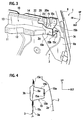
- FIG. 1 and FIG. 3 on a rear end portion of the door inner panel 3 in the fore-and-aft direction, there is an end wall 3c formed by bending the door inner panel 3, extended toward outside of the vehicle, and coupled to a rear edge portion of the door outer panel 2.
- a door sash 8 is extended upward from an inner surface of an upper end portion of the end wall 3c, and a base portion 8a of the door sash 8 is joined to an inner surface 3a in the vicinity of the end wall 3c of the door inner panel 3.
- a terminal end portion, specifically, a rear terminal end portion 10a of the outer waist reinforcement 10 in the longitudinal direction is coupled to the door inner panel 3 at a position between the rear end wall 3c of the door inner panel 3 and a rear terminal end portion 20a of the inner waist reinforcement 20 in the fore-and-aft direction.
- the terminal end portion 10a of the outer waist reinforcement 10 is coupled to the base portion 8a. Specifically, the terminal end portion 10a is coupled to a portion of the door inner panel 3, which is reinforced by the base portion 8a.
- the terminal end portion 10a of the outer waist reinforcement 10 is coupled to the door inner panel 3 while interposing a bracket 15 therebetween as a separate structural member from the outer waist reinforcement 10.
- the bracket 15 is formed into a shape having a hat-shape cross section.
- the bracket 15 includes an intermediate portion 15a coupled to a coupled portion (terminal end portion) 10a of the outer waist reinforcement 10, and a pair of leg portions 15b and 15b formed by bending the bracket 15, extended in the direction toward the door inner panel 3 from both end portions of the intermediate portion 15a in the vertical direction.
- the bracket 15 also includes attachment flange portions 15c and 15c formed by bending the bracket 15, extended in a direction in which the attachment flange portions 15c and 15c become apart from each other, from tip end portions of both the leg portions 15b and 15b, and attached to the door inner panel 3.
- terminal end portion 10a of the outer waist reinforcement 10 is coupled to the vicinity of the emboss portion 3b formed in the door inner panel 3 and shown by a broken line in FIG. 1.
- the emboss portion 3b is extended in the fore-and-aft direction in the upper portion of the door inner panel 3 while having a groove cross-sectional shape projected to the inside of the vehicle cabin.
- the attachment flange portions 15c and 15c of the bracket 15 with the hat-shape cross section are joined to both of upper and lower edge portions of the emboss portion 3b astride across the emboss portion 3b.
- the terminal end portion 10a of the outer waist reinforcement 10 is coupled to the door inner panel 3 at the position between the end wall 3c of the door inner panel 3 and the terminal end portion 20a of the inner waist reinforcement 20 in the fore-and-aft direction. Accordingly, the terminal end portion 10a can be joined to the door inner panel 3 at a portion where the inner waist reinforcement 20 is not present.
- positional accuracy between the upper edge portion of the door outer panel 2 and the upper edge portion of the door inner panel 3 in the opposing direction can be enhanced.
- molding accuracy of an opening peripheral edge portion of the opening portion 5 for moving the door glass 4 up and down can be enhanced.
- air tightness and glass retention between the waist weatherstrip 7 attached onto the opening peripheral edge portion of the opening portion 5 and the door glass 4 can be ensured.
- the terminal end portion 10a of the outer waist reinforcement 10, which is coupled to the door inner panel 3, is coupled to the vicinity of the emboss portion 3b formed in the door inner panel 3. Since the emboss portion 3b is highly rigid, coupling rigidity of the outer waist reinforcement 10 onto the door inner panel 3 is improved more, and eventually, the rigidity of the opening peripheral edge portion of the opening portion 5 can be further enhanced.
- the terminal end portion 10a of the outer waist reinforcement 10, which is coupled to the door inner panel 3, is coupled to the door inner panel 3 with the bracket 15 interposed therebetween as a separate structural member therefrom.
- the bracket 15 formed as a separate structural member has versatility to doors of various vehicles. Accordingly, only a body portion of the outer waist reinforcement 10 corresponding to the door 1 is formed, thus making it possible to use the bracket 15 common to each of the vehicle types. Thus, a cost reduction of the vehicle can be achieved.
- the bracket 15 is formed, into the shape having the hat-shape cross section, with the intermediate portion 15a, the leg portions 15b and 15b, and the flange portions 15c and 15c. Accordingly, a structure of the bracket 15 is simplified, thus making it possible to provide the bracket 15 at low cost.
- the rear end portion of the hemming-coupled portion K between the upper flange portion 14 of the outer waist reinforcement 10 and the upper edge portion of the door outer panel 2 comes close, in the fore-and-aft direction, to the spot-welded portions of the bracket 15 to the door inner panel 3. Accordingly, it becomes possible to effectively restrict deformation of the outer waist reinforcement 10 against application of a load to the door outer panel 2, and the rigidity of the opening portion 5 can be further enhanced.
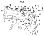
- FIG. 5 shows a second embodiment of the present invention.
- the same reference numerals are assigned to the same constituents as those in the first embodiment, and a description will be made of the second embodiment while omitting a duplicate description.
- This embodiment basically has a similar construction to that of the first embodiment.
- This embodiment is also constructed in such a manner that the upper inner surfaces 2a and 3a respectively of the door outer panel 2 and the door inner panel 3 are reinforced by being attached with the long outer waist reinforcement 10 and inner waist reinforcement 20. Also, in such a manner that the rear terminal end portion 10a of the outer waist reinforcement 10 is coupled to the door inner panel 3 between the rear end wall 3c of the door inner panel 3 and the rear terminal end portion 20a of the inner waist reinforcement 20.
- a particularly different point of this embodiment from the first embodiment is in that an attachment portion 16 onto the door inner panel 3, which corresponds to the bracket 15 of the first embodiment, is formed on the terminal end portion 10a of the outer waist reinforcement 10 integrally therewith.
- the attachment portion 16 is formed into a shape having a hat-shape cross section.
- the attachment portion 16 includes the terminal end portion 10a, a pair of leg portions 16a and 16a formed by bending the attachment portion 16, extended in the direction toward the door inner panel 3 from both end portions of the terminal end portion 10a in the vertical direction, and attachment flange portions 16b and 16b formed by bending the attachment portion 16, extended in the direction in which the attachment flange portions 16b and 16b become apart from each other, from tip end portions of both the leg portions 16a and 16a, and attached to the door inner panel 3.
- attachment flange portions 16b and 16b be joined to both of the upper and lower edge portions of the emboss portion 3b astride across the emboss portion 3b.
- the outer waist reinforcement 10 is joined to the door inner panel 3 at the portion where the inner waist reinforcement 20 is not preset, thus making it possible to enhance the molding accuracy of the opening peripheral edge portion of the opening portion 5 for moving the door glass 4 up and down.
- the attachment portion 16 is formed integrally with the outer waist reinforcement 10. Accordingly, the number of parts is reduced, thus making it possible to reduce the number of assembly man-hours thereof.
- the opening portion structure of the invention of this application is the opening portion structure in which an opening portion (5) is provided between edge portions of an outer panel (2) and an inner panel (3), and inner surfaces (2a, 3a) of the edge portions respectively of the outer panel (2) and the inner panel (3) are reinforced by an outer reinforcement (10) and an inner reinforcement (20), in which terminal end portions (10a) of the outer waist reinforcement (10) in the longitudinal direction are coupled to the inner panel (3) at positions inside both end walls (3c) of the inner panel (3) and outside terminal end portions (20a) of the inner reinforcement (20) in the longitudinal direction.
- the opening portion structure of the present invention has been described by taking as an example the case of the opening portion of the side door 1, such as a front door and a rear door, installed on the side surface of the vehicle.
- the opening portion is not limited to the above, and just needs to be an opening portion provided between the edge portions of the outer panel and the inner panel, in which the inner surfaces of the edge portions are reinforced by the reinforcements, respectively.
- the opening portion structure of the invention of this application can also be applied, for example, to an opening portion provided on a back door, in which a window glass is made movable up and down therein.
- this embodiment has been shown by taking as an example the rear portion of the door 1, the structure has been shown, in which the rear terminal end portion 10a of the outer waist reinforcement 10 is coupled to the door inner panel 3.
- the present invention can also be applied to a front terminal end portion of the outer waist reinforcement 10, which is disposed in a front portion of the door 1.
- the front terminal end portion be coupled to the door inner panel 3 between a front end wall of the door inner panel 3 and a front terminal end portion of the inner waist reinforcement 20.
- the present invention may be applied to either one of the rear terminal end portion 10a and front terminal end portion of the outer waist reinforcement 10. Then, the rigidity of the opening portion 5 can be enhanced at either one thereof to which the present invention is applied.
Landscapes
- Engineering & Computer Science (AREA)
- Mechanical Engineering (AREA)
- Seal Device For Vehicle (AREA)
- Window Of Vehicle (AREA)
- Body Structure For Vehicles (AREA)
- Load-Bearing And Curtain Walls (AREA)
Applications Claiming Priority (1)
| Application Number | Priority Date | Filing Date | Title |
|---|---|---|---|
| JP2005330166A JP4640127B2 (ja) | 2005-11-15 | 2005-11-15 | ドアウエスト部構造 |
Publications (3)
| Publication Number | Publication Date |
|---|---|
| EP1785302A2 true EP1785302A2 (fr) | 2007-05-16 |
| EP1785302A3 EP1785302A3 (fr) | 2009-07-22 |
| EP1785302B1 EP1785302B1 (fr) | 2010-07-14 |
Family
ID=37663116
Family Applications (1)
| Application Number | Title | Priority Date | Filing Date |
|---|---|---|---|
| EP06023363A Active EP1785302B1 (fr) | 2005-11-15 | 2006-11-09 | Structure de porte d'un véhicule automobile |
Country Status (7)
| Country | Link |
|---|---|
| US (1) | US7566091B2 (fr) |
| EP (1) | EP1785302B1 (fr) |
| JP (1) | JP4640127B2 (fr) |
| KR (1) | KR100850149B1 (fr) |
| CN (2) | CN100575653C (fr) |
| DE (1) | DE602006015412D1 (fr) |
| TW (1) | TWI319361B (fr) |
Cited By (1)
| Publication number | Priority date | Publication date | Assignee | Title |
|---|---|---|---|---|
| US9248729B2 (en) | 2013-12-19 | 2016-02-02 | Nissan North America, Inc. | Vehicle door structure |
Families Citing this family (16)
| Publication number | Priority date | Publication date | Assignee | Title |
|---|---|---|---|---|
| JP4240064B2 (ja) * | 2006-06-09 | 2009-03-18 | トヨタ自動車株式会社 | 車両用ドア構造 |
| JP5056233B2 (ja) * | 2007-07-19 | 2012-10-24 | 日産自動車株式会社 | 車両用ドア構造 |
| JP5303211B2 (ja) * | 2008-04-08 | 2013-10-02 | 本田技研工業株式会社 | 車両用ドア構造体およびその製造方法 |
| MY166989A (en) * | 2010-06-08 | 2018-07-27 | Nissan Motor | Vehicle door structure including locking member preventing movement of moveable member |
| JP5692776B2 (ja) * | 2010-06-11 | 2015-04-01 | シロキ工業株式会社 | 車両用ドアフレーム |
| DE102010046975A1 (de) * | 2010-09-29 | 2012-03-29 | Volkswagen Ag | Kraftfahrzeugtür |
| EP2604458B1 (fr) * | 2011-12-14 | 2014-04-09 | C.R.F. Società Consortile per Azioni | Portière de véhicule à moteur |
| JP6075985B2 (ja) * | 2012-07-17 | 2017-02-08 | シロキ工業株式会社 | 車両のドアフレーム構造 |
| DE102012215598B4 (de) * | 2012-09-03 | 2019-02-14 | Magna International Inc. | Aufprallträger |
| DE102013200073A1 (de) * | 2012-09-03 | 2014-03-06 | Magna International Inc. | Stoßfängerträger |
| JP5797856B2 (ja) * | 2015-01-29 | 2015-10-21 | シロキ工業株式会社 | 車両用ドアフレーム |
| JP6531742B2 (ja) * | 2016-09-13 | 2019-06-19 | トヨタ自動車株式会社 | 車両のサイドドア構造 |
| JP7047351B2 (ja) * | 2017-11-30 | 2022-04-05 | トヨタ紡織株式会社 | 乗物用ドア |
| US10625582B2 (en) | 2018-05-03 | 2020-04-21 | Ford Global Technologies, Llc | Vehicle trim panel interlock for limiting trim panel separation during an impact condition |
| CN110406479B (zh) * | 2019-08-28 | 2024-08-20 | 安徽安凯汽车股份有限公司 | 一种窗下沿封头装饰结构 |
| US11407291B1 (en) * | 2021-03-10 | 2022-08-09 | Honda Motor Co., Ltd. | Door structure |
Citations (5)
| Publication number | Priority date | Publication date | Assignee | Title |
|---|---|---|---|---|
| US5743588A (en) * | 1994-06-23 | 1998-04-28 | Ford Global Technologies, Inc. | Metallic section as reinforcement of a motor vehicle door |
| EP0989007A1 (fr) * | 1998-09-24 | 2000-03-29 | Automobiles Peugeot | Dispositif formant renfort et porte pour véhicule automobile |
| US6176542B1 (en) * | 1999-09-30 | 2001-01-23 | Delphi Technologies, Inc. | Vehicle door |
| JP2002154322A (ja) * | 2000-11-20 | 2002-05-28 | Suzuki Motor Corp | ドアのガラス受け部構造 |
| JP2002331836A (ja) * | 2001-05-11 | 2002-11-19 | Daihatsu Motor Co Ltd | 自動車用ドアのベルトライン構造 |
Family Cites Families (30)
| Publication number | Priority date | Publication date | Assignee | Title |
|---|---|---|---|---|
| US4689916A (en) * | 1980-03-31 | 1987-09-01 | Isuzu Motors Ltd. | Door glass assembly for automotive vehicles |
| JPS6412914A (en) * | 1987-07-07 | 1989-01-17 | Mazda Motor | Door glass lowering device for vehicle |
| DE3921289C1 (fr) * | 1989-06-29 | 1991-01-10 | Brose Fahrzeugteile Gmbh & Co Kg, 8630 Coburg, De | |
| US5339488A (en) * | 1990-11-13 | 1994-08-23 | Draftex Industries Limited | Sealing and wiping arrangement including inflatable chamber |
| JP3521452B2 (ja) * | 1992-11-09 | 2004-04-19 | マツダ株式会社 | 自動車のドア構造 |
| US5505024A (en) * | 1993-11-22 | 1996-04-09 | Chrysler Corporation | Vehicle door assembly |
| US5544448A (en) * | 1994-12-27 | 1996-08-13 | Ford Motor Company | Structural door belt seal |
| US5964063A (en) * | 1996-07-22 | 1999-10-12 | Honda Giken Kogyo Kabushiki Kaisha | Motor-vehicle door having window winder, method of assembling the door, and window sash assembly suitable for use in the door |
| KR19980059587A (ko) * | 1996-12-31 | 1998-10-07 | 김영귀 | 자동차 도어 |
| DE19709835B4 (de) * | 1997-02-26 | 2004-05-27 | Sommer Allibert-Lignotock Gmbh | Fahrzeugtür |
| DE19748970B4 (de) * | 1997-11-06 | 2005-12-08 | Ford Global Technologies, LLC (n.d.Ges.d. Staates Delaware), Dearborn | Integrale Türinnenverstärkung |
| DE19801842A1 (de) * | 1998-01-13 | 1999-07-22 | Sommer Allibert Lignotock Gmbh | Fahrzeugtür |
| DE19816533C2 (de) * | 1998-04-06 | 2001-08-09 | Brose Fahrzeugteile | Vorrichtung zur Befestigung einer Innenverkleidung für Fahrzeuge |
| JP3452490B2 (ja) * | 1998-07-03 | 2003-09-29 | 鬼怒川ゴム工業株式会社 | ドアウェザーストリップの端末構造 |
| JP4043122B2 (ja) * | 1998-12-17 | 2008-02-06 | 石川島運搬機械株式会社 | 車体方向転換装置を備えた補助リフト付昇降式駐車装置 |
| US6381906B1 (en) * | 1999-11-03 | 2002-05-07 | The Budd Company | Modular door with attachment mechanism |
| JP2002154332A (ja) * | 2000-09-07 | 2002-05-28 | Toyo Tire & Rubber Co Ltd | 自動車のドア構造 |
| DE10063459A1 (de) * | 2000-12-19 | 2002-06-27 | Wagon Automotive Gmbh | Leichtbautür für Kraftfahrzeuge |
| JP2002187500A (ja) * | 2000-12-21 | 2002-07-02 | Toyoda Gosei Co Ltd | 自動車用ウエザストリップ |
| JP3632850B2 (ja) * | 2002-01-16 | 2005-03-23 | 本田技研工業株式会社 | 自動車用ドア |
| JP3651604B2 (ja) * | 2002-06-11 | 2005-05-25 | ふそうエンジニアリング株式会社 | 車両用ドア |
| DE10230073A1 (de) * | 2002-07-01 | 2004-01-22 | Sai Automotive Sal Gmbh | Kraftfahrzeugtür |
| DE10256131A1 (de) * | 2002-11-29 | 2004-06-17 | Brose Fahrzeugteile Gmbh & Co. Kg, Coburg | Kraftfahrzeugtür |
| DE10326154B4 (de) * | 2003-06-06 | 2005-09-08 | Johnson Controls Interiors Gmbh & Co. Kg | Türmodul für Fahrzeugtür |
| CN1755054A (zh) * | 2004-09-27 | 2006-04-05 | 丰田自动车株式会社 | 门腰线结构 |
| US20060264554A1 (en) * | 2005-05-17 | 2006-11-23 | Arnold Lustiger | Fiber reinforced polypropylene composite door core modules |
| US7581751B2 (en) * | 2005-08-05 | 2009-09-01 | Honda Motor Co., Ltd. | Air bag device |
| US7568722B2 (en) * | 2005-08-30 | 2009-08-04 | Honda Motor Co., Ltd. | Arrangement structure of air bag device |
| JP4848913B2 (ja) * | 2005-11-28 | 2011-12-28 | 三菱自動車工業株式会社 | ドア構造 |
| DE102006009523A1 (de) * | 2006-02-28 | 2007-08-30 | Dr.Ing.H.C. F. Porsche Ag | Kraftfahrzeugtür |
-
2005
- 2005-11-15 JP JP2005330166A patent/JP4640127B2/ja active Active
-
2006
- 2006-11-09 DE DE602006015412T patent/DE602006015412D1/de active Active
- 2006-11-09 EP EP06023363A patent/EP1785302B1/fr active Active
- 2006-11-10 TW TW095141706A patent/TWI319361B/zh active
- 2006-11-14 US US11/598,692 patent/US7566091B2/en active Active
- 2006-11-14 KR KR1020060111992A patent/KR100850149B1/ko active IP Right Grant
- 2006-11-15 CN CN200610145164A patent/CN100575653C/zh active Active
- 2006-11-15 CN CNU2006201579614U patent/CN200964758Y/zh not_active Expired - Lifetime
Patent Citations (5)
| Publication number | Priority date | Publication date | Assignee | Title |
|---|---|---|---|---|
| US5743588A (en) * | 1994-06-23 | 1998-04-28 | Ford Global Technologies, Inc. | Metallic section as reinforcement of a motor vehicle door |
| EP0989007A1 (fr) * | 1998-09-24 | 2000-03-29 | Automobiles Peugeot | Dispositif formant renfort et porte pour véhicule automobile |
| US6176542B1 (en) * | 1999-09-30 | 2001-01-23 | Delphi Technologies, Inc. | Vehicle door |
| JP2002154322A (ja) * | 2000-11-20 | 2002-05-28 | Suzuki Motor Corp | ドアのガラス受け部構造 |
| JP2002331836A (ja) * | 2001-05-11 | 2002-11-19 | Daihatsu Motor Co Ltd | 自動車用ドアのベルトライン構造 |
Cited By (1)
| Publication number | Priority date | Publication date | Assignee | Title |
|---|---|---|---|---|
| US9248729B2 (en) | 2013-12-19 | 2016-02-02 | Nissan North America, Inc. | Vehicle door structure |
Also Published As
| Publication number | Publication date |
|---|---|
| KR20070051718A (ko) | 2007-05-18 |
| CN1966927A (zh) | 2007-05-23 |
| JP2007137115A (ja) | 2007-06-07 |
| JP4640127B2 (ja) | 2011-03-02 |
| DE602006015412D1 (de) | 2010-08-26 |
| CN200964758Y (zh) | 2007-10-24 |
| US20070108794A1 (en) | 2007-05-17 |
| TW200734215A (en) | 2007-09-16 |
| EP1785302A3 (fr) | 2009-07-22 |
| EP1785302B1 (fr) | 2010-07-14 |
| CN100575653C (zh) | 2009-12-30 |
| TWI319361B (en) | 2010-01-11 |
| KR100850149B1 (ko) | 2008-08-04 |
| US7566091B2 (en) | 2009-07-28 |
Similar Documents
| Publication | Publication Date | Title |
|---|---|---|
| EP1785302B1 (fr) | Structure de porte d'un véhicule automobile | |
| US7390049B2 (en) | Vehicle door | |
| US6725605B2 (en) | Safety device for a door window of a motor vehicle and method of making same | |
| US9346339B2 (en) | Vehicle door | |
| US7775580B2 (en) | Door glass guiding structure for vehicle | |
| EP2233334A1 (fr) | Structure de porte de véhicule et son procédé de production | |
| US20070145731A1 (en) | Blind member for vehicle, and gap-closing structure including blind member | |
| TWI412462B (zh) | 框架飾板安裝構造 | |
| KR101637303B1 (ko) | 자동차용 도어구조 | |
| EP1897715A2 (fr) | Structure de raidissement et procédé de raidissement pour panneau extérieur d'automobile | |
| US9573559B2 (en) | Front body structure of vehicle | |
| CN111409429B (zh) | 用于安装有相对的滑动车门的车辆的挡风雨条结构 | |
| JP4547707B2 (ja) | 自動車のルーフ補強構造 | |
| JP2008080819A (ja) | 自動車の下部車体構造 | |
| JPH06106975A (ja) | 車両のドア構造 | |
| JPS5881820A (ja) | フルプレスドアにおけるドアガラスのガイド部材保持構造 | |
| JPS6211681B2 (fr) | ||
| JP4396343B2 (ja) | ドアサッシュ構造 | |
| JPH11180147A (ja) | 自動車のフロントドア構造 | |
| JP2009262617A (ja) | 車両用ドア構造 | |
| JP5377125B2 (ja) | 車両用ドア構造 | |
| JP4195683B2 (ja) | 車両用スライドドア装置 | |
| KR102298866B1 (ko) | 자동차용 도어구조 | |
| JPH0635724Y2 (ja) | 車両のウェザーストリップ取付構造 | |
| JP2006298303A (ja) | 車両用ドア |
Legal Events
| Date | Code | Title | Description |
|---|---|---|---|
| PUAI | Public reference made under article 153(3) epc to a published international application that has entered the european phase |
Free format text: ORIGINAL CODE: 0009012 |
|
| 17P | Request for examination filed |
Effective date: 20061109 |
|
| AK | Designated contracting states |
Kind code of ref document: A2 Designated state(s): AT BE BG CH CY CZ DE DK EE ES FI FR GB GR HU IE IS IT LI LT LU LV MC NL PL PT RO SE SI SK TR |
|
| AX | Request for extension of the european patent |
Extension state: AL BA HR MK YU |
|
| PUAL | Search report despatched |
Free format text: ORIGINAL CODE: 0009013 |
|
| AK | Designated contracting states |
Kind code of ref document: A3 Designated state(s): AT BE BG CH CY CZ DE DK EE ES FI FR GB GR HU IE IS IT LI LT LU LV MC NL PL PT RO SE SI SK TR |
|
| AX | Request for extension of the european patent |
Extension state: AL BA HR MK RS |
|
| GRAP | Despatch of communication of intention to grant a patent |
Free format text: ORIGINAL CODE: EPIDOSNIGR1 |
|
| RIN1 | Information on inventor provided before grant (corrected) |
Inventor name: YAGI, TAKANORIC/O NISSAN MOTOR CO., LTD. |
|
| GRAS | Grant fee paid |
Free format text: ORIGINAL CODE: EPIDOSNIGR3 |
|
| AKX | Designation fees paid |
Designated state(s): DE FR GB |
|
| GRAA | (expected) grant |
Free format text: ORIGINAL CODE: 0009210 |
|
| AK | Designated contracting states |
Kind code of ref document: B1 Designated state(s): DE FR GB |
|
| REG | Reference to a national code |
Ref country code: GB Ref legal event code: FG4D |
|
| REF | Corresponds to: |
Ref document number: 602006015412 Country of ref document: DE Date of ref document: 20100826 Kind code of ref document: P |
|
| PLBE | No opposition filed within time limit |
Free format text: ORIGINAL CODE: 0009261 |
|
| STAA | Information on the status of an ep patent application or granted ep patent |
Free format text: STATUS: NO OPPOSITION FILED WITHIN TIME LIMIT |
|
| 26N | No opposition filed |
Effective date: 20110415 |
|
| REG | Reference to a national code |
Ref country code: DE Ref legal event code: R097 Ref document number: 602006015412 Country of ref document: DE Effective date: 20110415 |
|
| REG | Reference to a national code |
Ref country code: FR Ref legal event code: PLFP Year of fee payment: 10 |
|
| REG | Reference to a national code |
Ref country code: FR Ref legal event code: PLFP Year of fee payment: 11 |
|
| REG | Reference to a national code |
Ref country code: FR Ref legal event code: PLFP Year of fee payment: 12 |
|
| REG | Reference to a national code |
Ref country code: FR Ref legal event code: PLFP Year of fee payment: 13 |
|
| REG | Reference to a national code |
Ref country code: DE Ref legal event code: R084 Ref document number: 602006015412 Country of ref document: DE |
|
| REG | Reference to a national code |
Ref country code: GB Ref legal event code: 746 Effective date: 20230922 |
|
| PGFP | Annual fee paid to national office [announced via postgrant information from national office to epo] |
Ref country code: DE Payment date: 20241022 Year of fee payment: 19 |
|
| PGFP | Annual fee paid to national office [announced via postgrant information from national office to epo] |
Ref country code: GB Payment date: 20241022 Year of fee payment: 19 |
|
| PGFP | Annual fee paid to national office [announced via postgrant information from national office to epo] |
Ref country code: FR Payment date: 20241022 Year of fee payment: 19 |