EP1780705B1 - Mehrkanal-signaldekodierverfahren dafür, zugehörige vorrichtung, programm und aufzeichnungsmedium dafür - Google Patents
Mehrkanal-signaldekodierverfahren dafür, zugehörige vorrichtung, programm und aufzeichnungsmedium dafür Download PDFInfo
- Publication number
- EP1780705B1 EP1780705B1 EP05780405A EP05780405A EP1780705B1 EP 1780705 B1 EP1780705 B1 EP 1780705B1 EP 05780405 A EP05780405 A EP 05780405A EP 05780405 A EP05780405 A EP 05780405A EP 1780705 B1 EP1780705 B1 EP 1780705B1
- Authority
- EP
- European Patent Office
- Prior art keywords
- channel
- signal
- coding
- difference
- decoded
- Prior art date
- Legal status (The legal status is an assumption and is not a legal conclusion. Google has not performed a legal analysis and makes no representation as to the accuracy of the status listed.)
- Expired - Lifetime
Links
Images


Classifications
-
- G—PHYSICS
- G10—MUSICAL INSTRUMENTS; ACOUSTICS
- G10L—SPEECH ANALYSIS TECHNIQUES OR SPEECH SYNTHESIS; SPEECH RECOGNITION; SPEECH OR VOICE PROCESSING TECHNIQUES; SPEECH OR AUDIO CODING OR DECODING
- G10L19/00—Speech or audio signals analysis-synthesis techniques for redundancy reduction, e.g. in vocoders; Coding or decoding of speech or audio signals, using source filter models or psychoacoustic analysis
- G10L19/008—Multichannel audio signal coding or decoding using interchannel correlation to reduce redundancy, e.g. joint-stereo, intensity-coding or matrixing
Definitions
- the present invention relates to a decoding method, and an apparatus and program for the method, and a recording medium on which the program is recorded that are used for recording and transmitting multichannel signals such as audio, general, and environmental signals.
- a conventional predictive 1-channel coding and decoding method will be described with reference to Fig. 1 .
- a time-series digital signal provided through an input terminal 11 is divided by a frame divider 12 into short-time periods (called frames) each consisting of a predetermined number of samples, for example 1,024 samples.
- the digital signal is analyzed using linear prediction, frame by frame, to calculate prediction coefficients at a linear predictive analyzing section 13.
- the prediction coefficients are typically quantized by a quantizer 13a in the linear predictive analyzing section 13.
- a linear predicting section 14 uses the quantized prediction coefficients and the digital signal in the frame as inputs to perform linear prediction on the digital signal in the time direction to obtain a predicted value of each sample.
- the linear prediction is autoregressive forward prediction.
- a subtractor 15 subtracts the predicted value from the corresponding sample of the input digital signal to generate a prediction error signal.
- the linear prediction section 14 and the subtractor 15 constitute a prediction error generating section 16.
- the prediction error signal from the prediction error generating section 16 is entropy-coded using Huffman coding or arithmetic coding in a compressive coding section 17 and the result is outputted as an error code.
- the quantized prediction coefficients from the linear predictive analyzing section 13 are coded using entropy coding or vector quantization in a coefficient coding section 18 and the result is outputted as a coefficient code.
- the prediction coefficients may be scalar-quantized and outputted.
- an inputted compressed code is decoded in an expansion-decoding section 21 by using a decoding scheme corresponding to the coding scheme used by the compressive coding section 17 to generate a prediction error signal.
- An inputted coefficient code is decoded in a coefficient decoding section 22 using a decoding scheme corresponding to the coding scheme used by the coefficient coding section 18 to generate prediction coefficients.
- the decoded prediction error signal and prediction coefficients are inputted into a predictive synthesizing section 23, where they are predictive-synthesized to reproduce a digital signal.
- a frame combiner 24 sequentially combines frames of the digital signal and outputs them through an output terminal 25.
- the predictive synthesizing section 23 the digital signal to be reproduced and the decoded prediction coefficients are inputted into a regressive linear prediction section 26, where a prediction value is generated, and the prediction value and the decoded prediction error signal are added together in an adder 27 to reproduce the digital signal.
- a conventional method for coding a pair of stereo signals will be described with reference to Fig. 2 in which channels in a multichannel coding is reduced to coding of each pair of stereo signals.
- a first-channel digital signal x L (k) and a second-channel digital signal x R (k) in one frame are inputted into predictive coding sections 31 L and 31 R through input terminals 11 L and 11 R, respectively.
- the difference signal d(k) is inputted into a predictive coding section 31 D .
- the predictive coding sections 31 L , 31 R , and 31 D have the same configuration as that of the 1-channel predictive coding apparatus, for example as shown in Fig.
- Codes CS L , CS R , and CS D from the predictive coding sections 31 L , 31 R , and 31 D are inputted into a code length comparator 33.
- the code length comparator 33 selects two codes with the minimum total code amount from among the pairs in the three codes and outputs them as codes for the first and second digital signals x L (k) and x R (k). Using the correlation between channels of digital signals in this way can reduce the amount of coding code.
- Prediction error generators 34 L and 34 R generate linear prediction error signals e L (k) and e R (k) from digital signals x L (k) and x R (k).
- the liner prediction error signals e L (k) and e R (k) are inputted into entropy coders 35 L and 35 R and also inputted into a weighted difference generator 36. While the linear prediction coefficients are also coded separately as in the example shown in Fig. 1A , only those parts related to the linear prediction errors are shown in Fig. 3 .
- K denotes the number of samples of each signal in one frame, and ⁇ can be calculated as follows:
- E R T E L is the inner product, which can be calculated according to the following equations.
- the weighting factor calculated in the weight calculating section 36a is quantized in a factor quantizer 36d and the resulting weighting factor code q is outputted to a code length comparator 37.
- the quantized weighting factor is inverse-quantized in an factor inverse quantizer 36e and the linear prediction error signal e R (k) is multiplied by the resulting weighting factor ⁇ (q) at a multiplier 36b.
- the product is subtracted from the liner prediction error signal e L (k) in a subtractor 36c to generate a weighted difference signal d(k).
- the weighted difference signal d(k) is inputted into an entropy coder 35 D .
- Codes CS L and CS D from the entropy coders 35 L and 35 D are inputted in the code length comparator 37 and one of the codes that has a smaller code amount is outputted.
- the output from the code length comparator 37 and the output from the entropy coder 35 R are the coded outputs of the digital signals x L (k) and x R (k).
- the code length comparator 37 also codes the weighting factor ⁇ and adds it to the outputs. In this way, the signals can be compressed more efficiently than by the coding shown in Fig. 2 .
- first to sixth channel signal vectors X 1 - X 6 are grouped and coded in three pairs of stereo signals: the pair of the first and second channel signal vectors (X 1 , X 2 ), the pair of the third and fourth channel signal vectors (X 3 , X 4 ), and the pair of the fifth and sixth channel signal vectors (X 5 , X 6 ), If the order K of each vector is 2, the signal vectors X 1 - X 6 can be represented on a two-dimensional coordinate diagram with orthogonal coordinate axes representing the zero-order element x(0) and the first-order element x(1) of the vectors, as shown in Fig. 4A .
- the zero-order element d 1 , 2 (0) and the first-order element d 1 , 2 (1)of the difference signal vector between vectors X 1 and X 2 are x 1 (0) - x 2 (0) and x 1 (1) - x 2 (1), respectively.
- the difference signal vector has a large amplitude. Therefore, it is preferable that X 1 and X 2 be directly coded.
- the pair of vectors X 3 and X 4 be directly coded.
- the amplitude of the difference signal vector d 5 , 6 of the pair of vectors X 5 and X 6 is small. Therefore, the pair of vector X 5 and the difference signal vector d 5 , 6 may be coded.
- high compression rates are not necessarily achieved by generating and coding difference signal in this way.
- the weighting factor ⁇ is determined such that the energy value obtained by subtracting the one of each pair of vectors from the other vector multiplied by a weighting factor ⁇ (here, it is assumed that ⁇ > 0, because of the constraints of the drawing) is minimized, the weighted difference between them is the difference vector that is the perpendicular line drawn from one vector to the other (the reference signal) vector.
- the perpendicular line is often smaller that of the former vector. Therefore, the perpendicular line and the reference signal may simply be coded.
- the prediction error signal vectors of the first to sixth channels are vectors E 1 - E 6 whose order K is 2 and are the same as those vectors X 1 -X 6 , respectively, shown in Fig. 4A.
- Fig. 4B shows the vectors E 1 - E 6 on a two-dimensional coordinate diagram with orthogonal coordinate axes representing the zero-order element e(0) and the first-order element e(1) of the vectors.
- the weighting factor ⁇ is greater than or equal to 0.
- the weighted difference signal (vector) d 1,2 with the vector E 2 as a reference signal of the vector E 1 represents the perpendicular line drawn from vector E 1 to vector E 2 as shown in Fig. 4B .
- the weighted difference vector d 1,2 is smaller than vector E 1 .
- the weighted difference vector d 5 , 6 of the vectors E 5 and E 6 is smaller than vector E 5 .
- vectors E 3 and E 4 are opposite in direction to each other, therefore the weighted difference is even greater.
- the method can increase the compression rate by generating weighted difference signals, compared with the method shown in Fig. 2 in which difference signals without weights are generated.
- the method has the problem that there are pairs, such as the pair of vectors E 3 and E 4 , the compression rate of which cannot be increased by using the weighted difference signal.
- an input multichannel coded code is separated channel by channel and a reference signal (hereinafter also referred to as a "parent” or “master”) and a weighting factor determined on the basis of an auxiliary code of each channel are used to perform weighted addition to generate a decoded waveform signal.
- a reference signal hereinafter also referred to as a "parent” or "master”
- a weighting factor determined on the basis of an auxiliary code of each channel are used to perform weighted addition to generate a decoded waveform signal.
- at least one channel code is considered as the parent of itself in accordance with its auxiliary code and the decoded waveform signal of that channel is outputted as the decoded waveform signal obtained by the addition.
- the decoding method of the present invention includes at least one iteration of the process described above.
- the invention is concerned with decoding codes produced by a coding method, in which weighted difference signals are generated from a multichannel signal and weighted difference signals are further generated from those generated weighted difference signals. This process is repeated at least once. Consequently, the final weighted difference signals have smaller amplitudes and thus a greater compression rate can be achieved. Further, the weighted difference signals include weighted difference signals with a weighting factor of 0, that is, channel signals themselves. Therefore, signal vector E 4 for example becomes weighted difference signal d 4 , 56 with difference signal d 5 , 6 as the reference signal as shown in Fig, 4B , Thus, the compression rate is further improved.
- a multichannel signal coding code generated by the coding method of the present invention can be decoded by performing weighted addition by reusing additive-decoded waveform signals as parents.
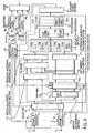
- FIG. 5 shows an exemplary functional configuration of a coding apparatus according to the present invention
- Fig. 6 shows a process performed in the coding apparatus.
- Each of input signals of first to I-th channels (hereinafter sometimes referred to as "channel signals”) inputted through input terminals 11 1 - 11 I is divided into short time periods (frames) each consisting of 256, 1,024, or 8,192 samples, for example, in a frame divider 12 1 - 12 I (step S1).
- I is an integer greater than or equal to 2.
- the channel signals are digital signals.
- determination is made in a multistage coding section 100 as to whether each of the first to I-th channel signals should be subjected to independent coding or weighted difference coding using one of the channel signals as a reference signal (hereinafter sometimes referred to as a "parent" or "master”) (step S2).
- At least one channel signal is chosen to be coded by independent coding.
- independent coding refers to coding of a channel signal by itself.
- the independent coding can be considered as coding using the channel signal itself as its parent or can be considered as weighted difference coding with a weighting factor of 0. Accordingly, the term weighted difference coding as used herein may sometimes refer to independent coding as well.
- the wording "at least one channel signal is coded by independent coding" means that 0 is chosen as the weighting factor for at least one.
- This sequential determination is performed in the multistage coding section 100 having a functional configuration as shown in Fig. 5 , for example, by following the process shown in Fig. 7A .
- the first to I-th channel signals X 1 - X I are inputted into a difference generating section 111.
- the difference generating section 111 generates weighted difference signals ⁇ (i,j) for all possible pairs of the channel signals (step S21).
- the signal ⁇ (i,j) represents a weighted difference signal of signal X i from its parent signal, signal X j . Because all difference signals used in the present invention are weighted difference signals, a weighted difference signal ⁇ (i,j) is Sometimes simply called a difference signal ⁇ (i,j) in the following description.
- a weight determining section 111 a calculates a weighting factor W(i, j) for the weighted difference signal ⁇ (i,j).
- the weighting factor can be calculated with the same calculation performed in the weight calculating section 36a in Fig. 3 .
- the difference signals ⁇ (i,j) and their weighting factors W(i, j) are temporarily stored in a difference memory 112.
- An individual energy calculating section 113 calculates the energy
- a difference energy calculating section 114 calculates the energies
- 2 L(i, j).
- the sum energies L(i, j) are sequenced in ascending order in an individual energy ascending ordering section 116 and the difference energies
- 2 are sequenced in ascending order in a difference energy ascending ordering section 117.
- the respective (i, j) are associated with the ordered energies and held with them.
- the sequence number parameters n and m in a register 118a in a sequential processing section 118 are set to 0 (step S23).
- a fetching section 118b fetches a channel identification number i (hereinafter distinctively referred to as the "child channel identification number i" for easy distinction from the parent channel) and the corresponding parent channel identification number j corresponding to the n-th smallest one of the sum energies L(i, j) from the individual energy ascending ordering section 116.
- a deciding section 118c decides whether the type of coding to be applied to the channel signal X j of the parent channel j has already been determined (step S24).
- step S24 If it is decided at step S24 that the type of coding to be applied to the channel j has not yet been determined, independent coding (difference coding with a weighting factor of 0) is chosen for the channel signal X j of the channel j (step S25) and difference coding using the channel signal X j as parent is chosen for the channel signal X i of the channel j's child channel (step S26).
- independent coding difference coding with a weighting factor of 0
- step S24 If it is decided at step S24 that the type of coding has already been determined, the process proceeds to step S26, where it is determined that the channel signal X i of the child channel i is to be coded by difference coding using the signal X j of the channel j as parent.
- step S26 "n" is incremented by 1 (step S27), and decision is made by the deciding section 118c as to whether the type of coding for all channel signals X 1 - X I have been determined (step S28). If not, a channel signal is determined for which difference coding is to be applied using a channel signal for which a coding type has already been determined as a candidate parent (step S29).
- Processing at step S29 may be performed as shown in Fig. 8 .
- 2 and its parent channel identification number j are fetched by the fetching section 118b from the difference ascending ordering section 117 and decision is made in the deciding section 118c as to whether the type of coding to be applied to the channel signal of its parent channel j has been determined (step S29a). If decision at step S29a is Yes, then it is determined that the channel signal of the channel i is to be coded by difference coding with the channel signal of the channel j as parent (step S29b). Then, m is initialized to 0 (step S29c).
- step S29d Decision is then made by the deciding section 118c as to whether coding types have been determined for all channel signals X i - X j . If not, the process returns to step S29a; otherwise the process at step S29 will end (step S29d).
- step S29e If decision at step S29a is No, m is incremented by 1 (step S29e). Then, the n-th smallest sum energy L(i, j) and the m-th smallest difference energy
- 2 are fetched by the fetching section 118b from the individual energy ascending ordering section 116 and the difference ascending ordering section 117, and L(i,j) is compared with
- step S29 If L(i,j) ⁇
- channel signal X 2 is coded by independent coding or difference coding using channel signal X 1 as parent in the conventional method whereas, according to the present invention, channel signal E 2 becomes difference signal d 2,3 with respect to the parent signal, channel signal E 3 . Therefore, a greater compression rate can be achieved.
- step S30 the deciding section 118c decides as to whether the type of coding has been determined for all channel signals X 1 -X I . If there remains a channel signal for which the type of coding has not yet been determined, the process returns to step S24; otherwise, step S2 will end.
- 2 by the fetching section 118b from the ascending ordering sections 116 and 117, decision at the deciding section 118c, and comparison at the comparator 118d are performed sequentially in accordance with instructions from a sequence control section 118e.
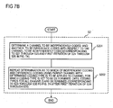
- step S2 in Fig. 7A can also be represented as shown in Fig. 7B .
- Step S201 of Fig. 7B corresponds to steps S21 through S23 in Fig. 7A and the first iteration of the process from step S24 and S26.
- Step S202 corresponds to the first iteration of the iterative process (steps S24 through S30) starting at step S27.
- Fig. 7C shows details of step S202. It can be seen that step S202 is the first iteration of the iterative process (steps S24 through S30) starting at step S27 in Fig. 7A .
- auxiliary code is shown in Fig. 9A .
- the auxiliary code is of the first to sixth channel signals X 1 - X 6 .
- a "1" in the end flag F EN indicates the end of the auxiliary code CAi of a channel.
- a "1" in the flag F R indicating whether the parent is the same as that in the previous frame indicates that the parent channel identification number j is the same as the parent channel identification number j in the auxiliary code CAi of that channel i in the previous frame.
- a comparator 119a compares the parent channel identification number j of the current frame with its corresponding parent channel identification number j contained in a previous-frame area 121d in an auxiliary code memory 121, which will be described later. If they match, 1 is set in F R and the succeeding parent channel identification number j will be omitted and F R will be immediately followed by the weighting.
- the parent channel j represents the channel identification number of the parent channel signal used in difference coding and the weighting factor W(i, j) represents the weighting factor used for the difference coding. It should be noted that the flag F R indicating whether the parent is the same as that in the previous frame can be omitted.
- Figs. 9A, 9B, and 9C show exemplary auxiliary codes.
- a "0" is set in the flag F EN at the left-most position of the auxiliary code CA1 of the first channel, indicating that it is followed by additional information, as shown on the right.
- a weighting factor W(i, j) for the difference signal ⁇ (i, j) is retrieved from the difference memory 112.
- a "1" is set in the end flag F EN at the beginning and there are not a parent channel identification number j and weighting factor W(i, j), indicating independent coding.
- independent coding can also be considered as weighted difference coding.
- the auxiliary code CA3 of the third channel is as shown in Fig. 9B .
- the auxiliary code CA thus generated is stored in the auxiliary code memory 121.
- Stored in the previous-frame area 121d in the auxiliary code memory 121 is at least the parent channel identification number j in the auxiliary code of the previous frame in association with each channel identification number.
- the type of coding used for a signal of a channel (hereinafter sometimes simply referred to as "used for a channel") is determined arid an auxiliary code CA is generated as described above. Then, a signal of a channel to be coded using independent coding is set as the input signal of that channel and inputted in the multistage coding section 100.
- a channel to be coded using difference coding For a channel to be coded using difference coding, its difference signal ⁇ (i,j) is set as the input signal of that channel and inputted into the multistage coding section 100. Furthermore, the process for determining the type of coding for an input signal of each channel and generating an auxiliary code is repeated at least once in the multistage coding section 100.
- an repetition control section 41 checks whether the coding type determining step for each channel has been completed (step S3). Whether the coding type determining process has been completed can be decided as follows. The coding type determining process can be terminated after a predetermined number of iterations are performed or when the reduction or reduction rate of the total difference signal energy drops to a predetermined value. If it is determined at step S3 that the coding type determining process has not yet been completed, an input channel signal to be coded using independent coding is inputted again and, for a channel signal for which difference coding is chosen, its difference signal ⁇ (i,j) is treated as the input channel signal of the i-th channel and an auxiliary code CA is generated (step S4). Then the process returns to step S2.
- All difference signals ⁇ (i,j) generated are inputted in memory area 112a in the difference memory 112 after the first iteration (the first step) of the coding type determining process, in memory area 112b after the second iteration (the second step), in memory area 112c after the third iteration (the third step), and so on.
- auxiliary codes CA generated are stored in memory area 121 a in the memory 121 after the first iteration of the coding type determining process, in memory area 121 b after the second iteration, in memory area 121 c after the third iteration, and so on.
- a combiner 44 combines the waveform codes CS1 - CSI from the waveform coders 43 1 - 43 I with the auxiliary codes CA1 - CAI from the auxiliary coding section 45 to output a multichannel coded code (step S6).
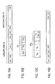
- Fig. 10A shows an exemplary multichannel coded code.
- Auxiliary codes CA1 - CAI of the first to I-th channels are arranged in order, followed by waveform codes CS1 - CSI of the first to I-th channels arranged in order.
- the auxiliary codes CAi of the i-th channel are sequenced as shown in Fig.
- the auxiliary code generated as a result of the first iteration is positioned as the first code CAi 1
- the auxiliary code generated as a result of the second iteration is positioned as the second code CAi 2
- the auxiliary code generated as a result of the third iteration is positioned as the third code CAi 3 .
- Step S2 of this process is most preferably performed by using the method shown in Fig. 7A or 7B .
- any method may be used that chooses at least one channel signal to be coded using independent coding and uses difference coding for the other channels.
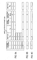
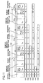
- Fig. 11 shows an detailed example including specific values in auxiliary codes CAi.
- the numeric value contained in the weighting factor W(i, j) (C w ) is a code C w representing a weighting factor.
- the auxiliary codes CA1 - CA6 of the first to sixth channels are shown in parallel. In the example shown in Fig. 10A , these code CA1 - CA6 are arranged in series.
- the first to fourth channels have a parent channel identification number j and weighting factor W(i, j) that are finite values, indicating that difference coding is used for these channels.
- the parent channel of the sixth channel is 6 and therefore difference coding is not used for the sixth channel but instead independent coding is applied to it, and the auxiliary code of the sixth channel has not yet been completed. While a "0" is contained in the weighting factor code of the sixth channel, the weighting factor code can be omitted because independent coding does not require a weighting factor code.
- the code CAi 2 generated by the second iteration indicates that difference coding is used for the first, second, and fourth channels. In particular, the code indicates that it has been determined that difference coding is to be applied again to weighted difference signals ⁇ (1, 3), ⁇ (2, 5), and ⁇ (4, 1) of the first, second, and fourth channels generated by the first iteration of the coding type determining process.
- the parent of the first channel ⁇ (1, 3) is the third channel, which is the difference signal ⁇ (3, 5).
- the end flag F EN of the third channel is 1, which indicates that it has been determined that the difference signal ⁇ (3, 5) of the third channel obtained as a result of the first iteration of the coding type determining process is to be independently coded.
- the sixth channel it has been determined by the second iteration of the coding type determining process that difference coding is applied to the original sixth channel signal X 6 inputted through the input terminal 11 6 by using the fourth channel as the parent and a weighting factor of 1.
- an input channel signal determined to be independently coded as well as the difference signal ⁇ (i, j) is inputted in the multistage coding section 100 and it can be determined that difference coding using the difference signal ⁇ (i, j) as the parent is to be applied to the input channel signal that has been previously determined to be independently coded.
- difference coding was not able to be used for the fourth channel signal E 4 in the first iteration of the coding type determining process, that is, the fourth channel signal E 4 was not able to be compressed.
- the conventional method described in the section "Problem to be solved by the invention” cannot compress the fourth channel.
- the recursive process according to the present invention can determine in the second iteration of the coding type determining process that difference coding using difference signal d 5,6 as the parent is to be applied, thereby further improving the compression rate.
- difference signal ⁇ (3, 5) is inputted into the multistage coding section 100 as an input channel signal in the third iteration of the coding type determining process.
- the repetition control section 41 in Fig. 5 retrieves ⁇ (3, 5) from memory area 112b in the difference memory 112 and inputs it into the multistage coding section 100 through the selector 42.
- the codes CAi 3 generated by the third iteration indicates that difference coding is used for the first channel.
- the parent used in the difference coding of the first channel ⁇ (1, 3) is the difference signal ⁇ (2, 5) of the second channel obtained in the second iteration of the coding type determining process.
- the end flag F EN of the second and sixth channel is 1.
- the parent used in difference coding of the fourth channel ⁇ (4, 2) is the difference signal ⁇ (1, 3) of the first channel.
- An auxiliary coding section 45 in Fig. 5 retrieves stored contents from the auxiliary code memory 121 and generates the auxiliary codes CA1 - CA6 shown in Fig. 11 , that is, number code sequences CAi 1 , CAi 2 , and CAi 3 of the auxiliary codes CAi of the channels.
- the parent channel identification numbers j are coded into number codes C j and weighting factors W(i, j) are coded into weight codes C W .
- Number codes C j and weighting factor codes C W may be stored when auxiliary codes are stored in each iteration of the coding type determining process in auxiliary code memory 121.
- Channel identification numbers i, j can be represented by binary numbers in a line, which may be used as the number codes C j .
- the auxiliary code CAi and waveform code CSi of the i-th channel may be paired with each other and the pairs may be arranged in sequence (CA1, CS1), ..., (CAI, CSI) as shown in Fig. 10D before being outputted as a multichannel coded code from the combiner 44.
- the coding type determining process may be repeated once or more than two times.
- the flag F R (indicating the parent is the same as that in the previous flame) may be omitted.
- the weighing factor W(i, j) for weighted difference signal may be calculated using a method other than the method described above, as described below.
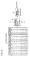
- An arrangement as shown in Fig. 12 is provided as the weight determining section 111a in the difference generator 111 shown in Fig. 5 .
- the weight identification numbers q are represented by five bits and are any of 0 to 31.
- a difference calculating section 46 subtracts the product of another channel signal (parent signal) X j and each weighting factor W q from the i-th channel signal X i .
- a minimum difference selector 47 selects the minimum value among the 32 differences calculated by the difference calculating section 46 and outputs it as a difference signal ⁇ (i, j) and also outputs as the weighting factor W(i, j) the weighting factor W q that provides the minimum value.
- all possible pairs are examined to find pairs that minimize the amount of a multichannel coded code.
- pairs of an independent coding channel and difference coding channel are sequentially chosen from among all pairs so that the sum of energies of signals, excluding auxiliary codes currently being outputted, is minimized.
- the number I of channels increases, significant amounts and time of processing will be required for examining all pairs.
- channel identification numbers 1 - I are arranged along the vertical and horizontal axes as shown in Fig. 13A and the pairs of the channels represented by the coordinate points in the two-dimensional domain are examined (searched) one by one.
- the two-dimensional domain may be divided into sub-areas and only some of those sub-areas may be searched in the coding type determining process. For example, only the hatched sub-areas in the two-dimensional domain shown in Fig. 13B may be searched through. That is, a sub-area defined by 1 ... I/2 on the horizontal axis and 1/2 + 1 ... I on the vertical axis and a sub-area defined by I/2 + 1 ... I on the horizontal axis and 1 ...
- each of the vertical and horizontal axes of the two-dimensional domain is divided into four and only the four sub-areas along a diagonal of the two-dimensional domain in the resulting 16 sub-areas may be searched through.
- Dividing the search domain as described above may slightly degrade the performance of compression but can prevent an explosive increase in the amount of processing due to the increase of the number of channels. Performance deterioration caused by the division can be minimized as follows, for example. All channel signals are clustered according to the similarity between them (the distance between the signals) in advance and the channels may be rearranged so that channels close to one another are fall in the same sub-area.
- Fig. 14 shows an exemplary functional configuration of a decoding apparatus
- Fig. 15 shows a process performed in the decoding apparatus.
- a multichannel coded code for example the multichannel coded code shown in Fig. 10A is inputted in a channel separator 51 through an input terminal 21.
- the channel separator 51 separates waveform codes CS1 - CSI from auxiliary codes CA1 - CAI, and provides the waveform codes CS1 - CSI to waveform decoders 52 1 - 52 I and provides the auxiliary codes CA1 - CAI to auxiliary code decoders 54 1 - 54 I (step S32).
- the waveform decoders 52 1 - 52 I decode the waveform codes CS1 - CSI, respectively, to generate waveform signals WAS1 - WASI by using a lossless expansion-decoding scheme corresponding to the lossless compressive coding scheme used in the waveform coders 43 1 - 43 I in Fig. 5 , and stores them in waveform storages 53 1 - 53 I (step S33).
- the auxiliary code decoders 54 1 -54 I decode the auxiliary codes CA1 - CAI, respectively, and temporarily stores the decoded results in the auxiliary code storages 55 1 - 55 I (step S34). It should be noted that any of steps S33 and S34 may be performed first or both of steps S33 and S34 may be performed in parallel.
- the waveform signals generated in the iterations of the coding type determining process and waveform signals in the auxiliary codes are decoded according to the auxiliary codes.
- the decoding is performed in the reverse of the order of the coding, starting with the last iteration of the coding type determining process. If the iteration of the coding type determining process is the P-th iteration, an iteration parameter p stored in a register 56a in a repetition control section 56, which performs an iterative multistage decoding process, is set to P (step S35).
- selectors 212 and 213 retrieve the waveform signals WAS1 - WASI from the waveform storages 53 1 - 53 I and input them in an iterative reproducing section 200.
- Weighted addition sections 211 1 - 211 I in the iterative reproducing section 200 reproduces signals before subtraction by weighted addition based on auxiliary codes CA1 p - CAI p in the p-th iteration to reproduce, from the input waveform signals WAS1 - WASI (step S36).
- a deciding section 56b decides whether p is equal to 1 (step S37). That is, the deciding section 56b decides whether the reproduction of the codes obtained in the first iteration of coding type determining process has been completed. If p # 1 at step S37, p is decremented by 1 (step S38) and the waveform signals that have not been processed in this reproduction stage (process) are treated as input waveform signals of the corresponding channels. Signals resulting from the weighted addition are inputted in the iterative reproduction section 200 as input waveform signals of the corresponding channels (step S39), and then the process returns to step 536.
- frame combiners 24 1 - 24 I sequentially combine the sum waveform signals from the weighted addition sections 211 1 - 211 I , respectively, and output reproduction signals X 1 - X I to output terminals 25 1 - 25 I .
- auxiliary codes CAi are sequenced CAi 1 , CAi 2 , CAi 3 in order of iteration number as shown in Fig. 10B , and the codes generated in the p-th iteration are arranged in the following order: end flag F EN , same-as-previous-frame flag F R , parent channel identification number j, and weighting factor code C W (or weighting factor W(i, j)).
- An end flag F EN is inserted in the position at which the auxiliary code of each channel ends.
- the numbers of bits of the flags, parent channel identification number, and, weighting factor are predetermined.
- the auxiliary decoding process generates auxiliary codes as shown in Fig. 11 , for example.
- the parent channel identification number j is obtained from the code that follows the F R (step S44). After the parent channel identification number is decoded (obtained), check is made as to whether the parent channel is the i-th channel itself (step S45). If the parent channel is not the i-th channel itself, the next code C w is obtained and decoded to obtain a weighting factor W(i, j) (step S46). For example, in the auxiliary code CA1 1 of the first channel in Fig.
- Fig. 17 shows details of the process performed at step S36 of Fig. 15 .
- the channel identification number "i" is initialized to 1 and a decoding completion flag F DE is initialized to 0 (step S51).
- decision is made as to whether the i-th channel is the parent channel of itself is made (step S52). If the i-th channel is the parent channel, the input waveform signal of the i-th channel is outputted, the decoding completion flag F DE is set to 1 (step S53), and "i" is incremented to i + 1 (step S54).
- step S52 If it is determined at step S52 that the i-th channel is not the parent of itself, then the process proceeds to step S54. After step S54, decision is made as to whether "i" is greater than the number of channels, I, if "i" is smaller than or equal to I (step S55), the process returns to step S52. In this way, a waveform signal decoded from an independently coded code in each iteration of iterative waveform reproduction is provided to an weighted addition section 211i. In the case of the auxiliary codes in Fig.
- Steps S56 to S61 described above are the steps of reproducing difference-decoded waveform signals.
- the first iteration of reproduction of the first channel coded code is performed on the basis of code CA1 3 of the third iteration of coding of the first channel shown in Fig. 11 .
- the parent channel j of code CA1 3 of the third iteration is 2 and the waveform signal of the parent has not been decoded in the steps before step S56.
- reproduction of the channel is performed in the first iteration of the reproduction at step S56 and the subsequent steps.
- the parent channel j of code CA4 3 of the third iteration of coding of the fourth channel is 1 and the input waveform signal of the first channel has not been processed (decoded) in the first iteration of the reproduction process, therefore the input waveform signal of the fourth channel cannot be processed.
- the process returns to step S56 and the reproduction process for the fourth channel input waveform signal is performed in the second iteration of the reproduction process at this stage based on the determination.
- independent coding can be considered as weighted difference coding using a channel itself as its parent and using a weighting factor of 0.
- "m" may be initialized to 1 at step S51 of Fig. 17 as shown in the parentheses, instead of initializing "i" to 1, and then the process may proceed from step S51 to step S56 as shown by a one-dotted chain line.
- steps represented as dashed blocks in Fig. 17 are added.
- determination at step S57 is Yes, decision is made as to whether the flag F R is 1 (step S62). If it is the same, the parent channel in the auxiliary code of the corresponding channel of the previous frame is used at step S63. If the parent is not the same, the parent channel indicated in the current auxiliary code is used at step S64 and the process proceeds to step S58.
- each of waveform signals outputted from the weighted addition sections 211 1 - 211 I in Fig. 14 is inputted in the selectors 212 and 213. Also inputted in the weighted addition sections 212 and 213 are decoded waveform signals WAS1 - WASI from the waveform storages 53 1 - 53 I , respectively.
- Each of the selectors 212 and 213 selects one of the decoded waveform signal and the waveform signal outputted from the weighted addition section as the input into each channel, in accordance with an instruction from the repetition control section 56.
- the selector 212 inputs the selected waveform signal into an adder 211b in the weighted addition section 211 1 - 211 I .
- the selector 212 inputs it as a child channel waveform signal.
- the selector 213 inputs the selected waveform signal into a multiplier 211a in the weighted addition section 211 1 - 211 I . That is, the selector 213 inputs the signal as a parent channel waveform signal.
- Each of the decoding weighting factors from the auxiliary code storages 55 1 - 55 I is inputted in an associated multiplier 211 a.
- the product from each of the multipliers 211 a is inputted in its associated adder 211b and the sum from the adder 211b is outputted from the weighted addition section 211 1 - 211 I as a waveform signal.
- the weighting code C w may be decoded at a weight decoder 211 c in each weighted addition section, rather than in the auxiliary code decoders 54 1 - 54 I ,
- Provided in the repetition control section 56 are registers 56a, 56b for storing parameters p, i, and, m used for the process described above and a deciding section 56c which makes decision at each decision step in Figs. 15 and 17 .
- storage for storing F ED associated with each channel is also provided.
- the waveform code of each channel may be decoded when its decoded waveform signal is required, rather than decoding it in advance.
- the waveform code CSi of the channel (the channel that is the parent of itself) is decoded and the decoded waveform signal ASi is outputted as shown in the parentheses in step S53 in Fig. 17 .
- the iterative reproduction process is started from the coding stage next to the third iteration code CAi 3 , that is, the fourth iteration code CAi 4 , in the example shown in Fig. 11 .
- codes that can be reproduction-coded may be processed on the basis of the auxiliary code in the code of multi channel, in order, starting with the first channel, and codes that cannot be reproduction-decoded may be skipped.
- codes that can be processed may be processed, in order, starting with the first channel. This process is repeated. In doing this, a decoded waveform signal, decoded difference signal, addition signal (difference signal), WASi, ⁇ (i, j), ⁇ (i, j,), and so on obtained as a result of each iteration are stored in a storage and an appropriate parent is retrieved from the storage and used for weighted addition.
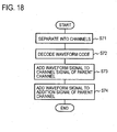
- the decoding method according to the present invention is characterized by repeating weighted addition in such a manner that weighted addition between a difference waveform signal and another waveform signal is performed to reproduce a waveform signal and then weighted addition between the waveform signal reproduced by the weighted addition and another difference signal is performed to reproduce another waveform signal. Therefore, any processing procedure for the decoding method may be used that includes the process shown in Fig. 18 .
- a multichannel coded code is separated into channel codes (step S71), at least one of independent coded code is decoded to generate a channel waveform signal (step S72).
- the channel waveform signal is used as the parent to perform weighted addition of another waveform signal to generate a difference waveform signal or a channel waveform signal (step S73).
- the waveform signal generated by the weighted addition is used as the parent to perform weighted addition of another waveform signal to generate another channel waveform signal or difference signal (step S74).
- the present invention can also be applied to a prediction error signal series or a prediction parameter series resulting from linear prediction performed for each channel as well as a signal series itself. If the present invention is applied to both of them, each auxiliary code may be independently used. If part of an auxiliary code (for example a parent channel identification number) is the same, the auxiliary code may be shared.
- FIG. 19 An example of this is shown in Fig. 19 .
- Channel signals from frame dividers 12 1 - 12 I are inputted in prediction analyzing sections 13 1 - 13 I , respectively, and prediction error generators 16 1 -16 I , respectively.
- prediction error signals are generated in the prediction error generators 16 1 - 16 I .
- These prediction error signals are inputted in a multistage error coding section 61.
- Prediction coefficient signals generated in the prediction analyzing sections 13 1 - 13 I are inputted in a multistage coefficient coding section 62.
- the multistage error coding section 61 and the multistage coefficient coding section 62 have the same functional configuration as that of the multistage coding section 100 depicted in Fig. 5 and described above.
- Difference signals from the multistage error coding section 61 and prediction error signals to be independently coded are inputted in an error waveform coder 63.
- the error waveform coder 63 codes the prediction error signal or its difference signal of each channel.
- prediction coefficient signals to be independently coded or difference signals from the multistage coefficient coding section 62 are inputted in a coefficient coding section 64.
- the coefficient coding section 64 codes the prediction coefficient signal or its difference signal of each channel.
- a comparator 65 compares an auxiliary code from an auxiliary code generator 61a in the multistage error coding section 61 with an auxiliary code from an auxiliary code generator 62a in the multistage coefficient coding section 62 to see whether the parent channel identification numbers of the same channel are identical to each other.
- a correcting section 66 simply sets, instead of the parent channel identification number of corresponding one of the channels (for example an auxiliary code from the multistage coefficient coding section 62), a flag indicating that the channel identification number is the same as the corresponding channel in the auxiliary code of the prediction error signal.
- a combiner 67 combines the waveform code from the error waveform coder 63 with its corresponding auxiliary code to generate a multichannel coded code of the prediction error signal.
- Another combiner 68 combines the coefficient code from the coefficient coding section 64 with the auxiliary code from the correcting section 66 to generate a multichannel coded code of the prediction coefficients.
- each of the error waveform coder 63 and the coefficient coding section 64 there are provided waveform selectors 49 1 - 49 I shown in Fig. 5 though not shown in Fig. 19 .
- prediction parameters are PARCOR coefficients
- pairs signals of multiple channels are inputted in stereo coding signal generators 71 through input terminals 11 1 - 11 I .
- Each of the stereo coding signal generators 71 generates a difference signal L - R between the stereo left signal L, which is one of two input signals, and the right signal R, which is the other.
- the stereo coding signal generator 71 also selects two of the three signals that have the smallest code amount, or smaller energies.
- Each of prediction error generators 16 1 - 16 I generates a prediction error signal from the two signals provided from each stereo coding signal generator 71 and inputs it in a multichannel coding section 72 as a multichannel signal X 1 - X I in Fig. 5 .
- a multichannel coding section 72 Provided in the multichannel coding section 72 is a multistage coding section 100 as shown in Fig. 5 . This process can improve the compression rate compared with directly coding input signals of multiple channels in a multichannel coding section.
- Fig. 20B shows a functional configuration of an apparatus at a decoding end.
- an iterative reproducing section 200 as shown in Fig. 14 .
- a multichannel coded code is inputted in the multichannel decoding section 73.
- Reproduction channel signals from the iterative reproducing section 200 in the multichannel decoding section 73 are inputted in predictive synthesizing sections 23 1 - 23 I , where predictive synthesis is performed.
- the predictive-synthesized output signals are grouped in pairs in order starting with the first channel as in the coding process, and are inputted in stereo separators 74.
- Each of the stereo separators 74 outputs a left signal L and a right signal R based on the two input signals.
- an input selector 81 groups channel signals inputted through input terminals 11 1 - 11 I in pairs in order starting with the first channel and inputs the pairs in stereo coding signal generators 71 described with reference to Fig. 20A .
- Each of prediction error generators 16 1 - 16 I generates a prediction error signal from the two signals provided from the stereo coding signal generator 71.
- Compressive coding sections 17 1 - 17 I code prediction error signals using lossless compressive coding such as entropy coding and provides the codes to a combiner 83, which outputs a multichannel coded code.
- the input selector 81 also inputs the input channel signals to prediction error generators 82 1 - 82 I .
- the prediction error generators 82 1 - 82 I input prediction error signals into a multichannel coding section 72 as channel signals X 1 - X I .
- the multichannel coding section 72 outputs a multichannel coded code.
- An output selector 84 selects one of the multichannel coded codes provided from the combiner 83 or the multichannel coding section 72 depending on the selection at the input selector 81.
- Decoding of the multichannel coded code is performed as shown in Fig. 21B , for example.
- An input multichannel coded code is separated into channel codes, the first to I-th channel codes, by a channel separator 51.
- An input selector 85 inputs the separated first to I-th channel codes into expansion-decoding sections 21 1 - 21 I or a multichannel decoding section 73 according to a code indicating the selection at the output selector 84 at the coding end. If the codes are inputted in the expansion-decoding sections 21 1 - 21 I , the expansion-decoding sections 21 1 -21 I decode the first to I-th channel codes, respectively.
- Predictive synthesizing sections 23 1 - 23 I perform predictive synthesis of the signals to group them in pairs and inputs the pairs into stereo separators 74.
- the stereo separators 74 input the separated first to I-th channel reproduction signals in an output selector 87. If the input selector 85 inputs the first to I-th channel codes into the multichannel decoding section 73, the multichannel decoding section 73 decodes them.
- Predictive synthesizing sections 86 1 - 86 I predictively synthesize the first to I-th channel reproduction signals and provide them to the output selector 87.
- the output selector 87 outputs one of the first to I-th channel reproduction signals in accordance with the selection at the input selector 85.
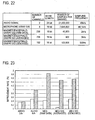
- the coding method shown in Fig. 6 was applied to 2 channels of audio signals, 8 channels of microphone array (audio) signals, 256 channels of Magnetoencephalograph signals (raw data), 256 channels of Magnetoencephalograph signals (averaged), and 192 channels of Magnetoencephalograph signals (denoised) as shown in Fig. 22 .
- the word length (the number of bits per sample) of each channel signal and the number of samples and sampling frequency of each channel are as shown in Fig. 22.
- Fig. 23 shows the relative improvement rates of the amounts of codes generated by the multichannel coding according to the present invention and the amounts of codes generated by the coding method shown in Fig. 2 , with respect to the amount of code Vu generated by independent coding of each channel.
- the improvement rate was defined as (Vu - Vp)/Vu x 100 (%), where Vp denotes the amount of a code compressed by coding.
- the white bars in Fig. 23 represent the improvement rates by the method shown in Fig. 2 and the hatched bars represent the improvement rates by the method according to the present invention. It can be seen from the bar graph that the present invention is significantly advantageous over the method shown in Fig 2 .
- a computer can be caused to function as the coding apparatus and decoding apparatus according to the present invention.
- a program for causing the computer to perform the steps of, for example, the method shown in Fig. 6 recorded on a recording medium such as a CD-ROM, magnetic disk, or semiconductor storage medium may be installed in the computer or the program may be downloaded to the computer over a network, to cause the computer to execute the program.
Landscapes
- Engineering & Computer Science (AREA)
- Physics & Mathematics (AREA)
- Mathematical Physics (AREA)
- Computational Linguistics (AREA)
- Signal Processing (AREA)
- Health & Medical Sciences (AREA)
- Audiology, Speech & Language Pathology (AREA)
- Human Computer Interaction (AREA)
- Acoustics & Sound (AREA)
- Multimedia (AREA)
- Compression, Expansion, Code Conversion, And Decoders (AREA)
- Signal Processing For Digital Recording And Reproducing (AREA)
Claims (10)
- Mehrkanalsignal-Decodierverfahren, das einen Signalformdecodierschritt eines Decodierens eines Codestrings jedes Kanals umfasst, der in einem Eingangsmehrkanalcode enthalten ist, um ein decodiertes Signalformsignal zu erzeugen,
wobei das Verfahren aufweist:einen zusätzlichen Decodierschritt (S34) zum Decodieren, aus Hilfscode in dem Eingangsmehrkanalcode, von Information, die für jeden Rahmen jedes Kanals, der in dem Eingangsmehrkanalcode enthalten ist, anzeigt, ob das Kanalsignal codiert wurde durch eine Codieroperation auf dem Kanalsignal selbst, wobei die Codieroperation im Folgenden als unabhängiges Codieren bezeichnet wird, oder eine Codieroperation auf einer gewichteten Differenz zwischen dem Kanalsignal und einem Kanalsignal eines anderen Kanals, im Folgenden als Vorläufer- bzw. Eltern-Kanal bezeichnet, wobei die Codieroperation im Folgenden als Differenzcodierung bezeichnet wird, und Information über eine Gewichtung in dem Fall der Differenzcodierung;einen ersten Reproduktionsschritt (S36, S52-S55), wenn der Kanal ein Kanal ist, auf den ein unabhängiges Codieren angewendet wird, eines Vorsehens eines decodierten Signalformsignals des Kanals als ein decodiertes Kanalsignal;einen zweiten Reproduktionsschritt (S36, S56-S61), wenn der Kanal ein Kanal ist, auf den ein Differenzcodieren angewendet wird, und ein decodiertes Kanalsignal des Vorläufers des Kanals erlangt wurde, eines Hinzufügens des decodierten Signalformsignals des Kanals zu einem gewichteten decodierten Kanalsignal des Eltern-Kanals, um ein decodiertes Kanalsignal vorzusehen; undeinen Schritt eines Wiederholens des ersten Reproduktionsschritts und des zweitem Reproduktionsschritts, bis die decodierten Kanalsignale aller Kanäle erlangt sind. - Mehrkanalsignal-Decodierverfahren gemäß Anspruch 1, wobei der Prozess des ersten Reproduktionsschritts (S36, S52-S55) für jeden Kanal, auf den ein unabhängiges Codieren angewendet wird, vor dem zweiten Reproduktionsschritt wiederholt wird.
- Mehrkanalsignal-Decodierverfahren gemäß Anspruch 1 oder 2, wobei:der Eingangsmehrkanalcode Hilfscodes enthält, die Teile von Information (CAi: CAi1, CAi2, CAi3) für mehrere Stufen (P) eines mehrstufigen Decodierprozesses für jeden Kanal repräsentieren, wobei jedes Informationsteil Information (j) umfasst, die einen Eltern-Kanal anzeigt, der verwendet wurde zum Codieren des jeweiligen Kanals durch eine Codieroperation auf einer gewichteten Differenz zwischen dem Kanalsignal jedes Kanals und einem Kanalsignal des Eltern-Kanals, und Information über eine Gewichtung;der Hilfsdecodierschritt (34) weiter aus den Hilfscodes Information decodiert, die für jeden Kanal einen Eltern-Kanal anzeigt, der für eine Codieroperation auf einer gewichteten Differenz mit dem jeweiligen Kanal verwendet wurde, und Information über eine Gewichtung (W) für jede Stufe; unddas Mehrkanalsignal-Decodierverfahren weiter aufweist:einen mehrstufigen Verarbeitungsschritt (S39) zum Verwenden des decodierten Kanalsignals jedes Kanals, das an dem Wiederholungsschritt erlangt wurde, als ein Kanalsignal des jeweiligen Kanals, und Wiederholen der ersten und zweiten Reproduktionsschritte und des Wiederholungsschritts für jede der mehreren Stufen gemäß der Information über die jeweilige Stufe.
- Mehrkanalsignal-Decodierverfahren gemäß Anspruch 1 oder 2, wobei:der Eingangsmehrkanalcode Teile von Information (CAi: CAi1, CAi2, CAi3) für mehrere Stufen (P) eines mehrstufigen Decodierprozesses für jeden Kanal enthält, wobei jedes Informationsteil Information umfasst, die anzeigt, ob jeder Kanal durch unabhängiges Codieren oder durch Differenzcodieren codiert wurde, und Information über eine Gewichtung in dem Fall der Differenzcodierung; unddas Verfahren weiter aufweist:einen mehrstufigen Verarbeitungsschritt (S39) zum Verwenden des decodierten Kanalsignals jedes Kanals, das an dem Wiederholungsschritt erlangt wurde, als ein Kanalsignal des jeweiligen Kanals, und Wiederholen des Prozesses des ersten Reproduktionsschritts, des zweiten Reproduktionsschritts und des Wiederholungsschritts für jede der mehreren Stufen gemäß der Information über die jeweilige Stufe.
- Mehrkanalsignal-Decodiervorrichtung, die umfasst:einen Signalformdecodierabschnitt (52I bis 52I, 53I bis 53I), der ausgebildet ist, einen Codestring jedes Kanals zu decodieren, der in einem Eingangsmehrkanalcode enthalten ist, um ein decodiertes Signalformsignal jedes Kanals zu erzeugen,einen Hilfsdecodierabschnitt (54I bis 54I, 55I bis 55I, 56), der ausgebildet ist zum Decodieren, aus Hilfscode in dem Eingangsmehrkanal, von Information, die für jeden Rahmen jedes Kanals anzeigt, ob das Kanalsignal codiert wurde durch eine Codieroperation auf dem Kanalsignal selbst, wobei die Codieroperation im Folgenden als unabhängiges Codieren bezeichnet wird, oder eine Codieroperation auf einer gewichteten Differenz zwischen dem Kanalsignal und einem Kanalsignal eines anderen Kanals, im Folgenden als Eltern-Kanal bezeichnet, wobei die Codieroperation im Folgenden als Differenzcodierung bezeichnet wird, und Information über eine Gewichtung in dem Fall der Differenzcodierung;einen Wiederholungsreproduktionsabschnitt (212, 213, 211I bis 211I), der ausgebildet ist zum Durchführen von Prozessen eines Vorsehens, wenn der Kanal ein Kanal ist, auf den ein unabhängiges Codieren angewendet wird, eines decodierten Signalformsignals des Kanals als ein decodiertes Kanalsignal, und, wenn der Kanal ein Kanal ist, auf den ein Differenzcodieren angewendet wird, und ein decodiertes Kanalsignal des Vorläufers des Kanals erlangt wurde, eines Hinzufügens des decodierten Signalformsignals des Kanals zu einem gewichteten decodierten Kanalsignal des Eltern-Kanals, um ein decodiertes Kanalsignal vorzusehen, und Wiederholen der Prozesse des Vorsehens und Hinzufügens, bis die decodierten Kanalsignale aller Kanäle erlangt sind.
- Mehrkanalsignal-Decodiervorrichtung gemäß Anspruch 5, wobei der Wiederholungsreproduktionsabschnitt (212, 213, 211I bis 211I) ausgebildet ist, den Prozess eines Vorsehens eines decodierten Signalformsignals für jeden Kanal, auf den ein unabhängiges Codieren angewendet wird, als ein decodiertes Kanalsignal zu wiederholen vor dem Prozess für einen Kanal, auf den ein Differenzcodieren angewendet wird.
- Mehrkanalsignal-Decodiervorrichtung gemäß Anspruch 5 oder 6, wobei:der Eingangsmehrkanalcode Hilfscodes enthält, die Teile von Information (CAi: CAi1, CAi2, CAi3) für mehrere Stufen (P) eines mehrstufigen Decodierprozesses für jeden Kanal repräsentieren, wobei jedes Informationsteil Information (j) umfasst, die einen Eltern-Kanal anzeigt, der verwendet wurde zum Codieren des jeweiligen Kanals durch eine Codieroperation auf einer gewichteten Differenz zwischen dem Kanalsignal jedes Kanals und einem Kanalsignal des Eltern-Kanals, und Information über eine Gewichtung;der Hilfsdecodierabschnitt (54I bis 54I, 55I bis 55I, 56) ausgebildet ist,aus den Hilfscodes Information zu decodieren, die für jeden Kanal einen Eltern-Kanal anzeigt, der für eine Codieroperation auf einer gewichteten Differenz mit dem jeweiligen Kanal verwendet wurde, und Information über eine Gewichtung; unddie Mehrkanalsignal-Decodiervorrichtung weiter aufweist:einen Auswahlabschnitt (212, 213), der ausgebildet ist, das decodierte Kanalsignal jedes Kanals, das an dem Wiederholungsreproduktionsabschnitt erlangt wurde, in den Wiederholungsreproduktionsabschnitt (211I bis 211I) als die decodierte Signalform erneut einzugeben; undeinen Wiederholungssteuerungsabschnitt (56), der ausgebildet ist, die Operationen des Wiederholungsreproduktionsabschnitts und des Auswahlabschnitts für jede der mehreren Stufen gemäß der Information über die jeweilige Stufe zu wiederholen.
- Mehrkanalsignal-Decodiervorrichtung gemäß Anspruch 5 oder 6, wobei der Eingangsmehrkanalcode Teile von Information (CAi: CAi1, CAi2, CAi3) für mehrere Stufen (P) eines mehrstufigen Decodierprozesses für jeden Kanal enthält, wobei jedes Informationsteil Information umfasst, die anzeigt, ob jeder Kanal durch unabhängiges Codieren oder durch Differenzcodieren codiert wurde, und Information über eine Gewichtung in dem Fall der Differenzcodierung, wobei die Vorrichtung weiter umfasst:einen Auswahlabschnitt (212, 213), der ausgebildet ist, das decodierte Kanalsignal jedes Kanals, das an dem Wiederholungsreproduktionsabschnitt erlangt wurde, in den Wiederholungsreproduktionsabschnitt (211I bis 211I) als das decodierte Signalformsignal jedes Kanals erneut einzugeben; undeinen Wiederholungssteuerungsabschnitt (56), der ausgebildet ist, die Operationen des Wiederholungsreproduktionsabschnitts und des Auswahlabschnitts für jede der mehreren Stufen gemäß der Information über die jeweilige Stufe zu wiederholen.
- Decodierprogramm, das Anweisungen aufweist, die bei Ablauf auf einem Computer, den Computer veranlassen, die Schritte des Mehrkanalsignal-Decodierverfahrens gemäß einem der Ansprüche 1 bis 4 durchzuführen.
- Computerlesbares Aufzeichnungsmedium, auf dem das Programm gemäß Anspruch 9 gespeichert ist.
Priority Applications (1)
| Application Number | Priority Date | Filing Date | Title |
|---|---|---|---|
| EP10002014.8A EP2200023B8 (de) | 2004-08-19 | 2005-08-17 | Mehrkanalsignalkodierungsverfahren und Vorrichtung und Programm für die Verfahren sowie ein Aufzeichnungsmedium mit dem darauf gespeicherten Programm |
Applications Claiming Priority (2)
| Application Number | Priority Date | Filing Date | Title |
|---|---|---|---|
| JP2004239665 | 2004-08-19 | ||
| PCT/JP2005/015015 WO2006019117A1 (ja) | 2004-08-19 | 2005-08-17 | 多チャネル信号符号化方法、その復号化方法、これらの装置、プログラム及びその記録媒体 |
Related Child Applications (2)
| Application Number | Title | Priority Date | Filing Date |
|---|---|---|---|
| EP10002014.8A Division EP2200023B8 (de) | 2004-08-19 | 2005-08-17 | Mehrkanalsignalkodierungsverfahren und Vorrichtung und Programm für die Verfahren sowie ein Aufzeichnungsmedium mit dem darauf gespeicherten Programm |
| EP10002014.8 Division-Into | 2010-02-26 |
Publications (3)
| Publication Number | Publication Date |
|---|---|
| EP1780705A1 EP1780705A1 (de) | 2007-05-02 |
| EP1780705A4 EP1780705A4 (de) | 2008-09-17 |
| EP1780705B1 true EP1780705B1 (de) | 2011-01-12 |
Family
ID=35907500
Family Applications (2)
| Application Number | Title | Priority Date | Filing Date |
|---|---|---|---|
| EP10002014.8A Expired - Lifetime EP2200023B8 (de) | 2004-08-19 | 2005-08-17 | Mehrkanalsignalkodierungsverfahren und Vorrichtung und Programm für die Verfahren sowie ein Aufzeichnungsmedium mit dem darauf gespeicherten Programm |
| EP05780405A Expired - Lifetime EP1780705B1 (de) | 2004-08-19 | 2005-08-17 | Mehrkanal-signaldekodierverfahren dafür, zugehörige vorrichtung, programm und aufzeichnungsmedium dafür |
Family Applications Before (1)
| Application Number | Title | Priority Date | Filing Date |
|---|---|---|---|
| EP10002014.8A Expired - Lifetime EP2200023B8 (de) | 2004-08-19 | 2005-08-17 | Mehrkanalsignalkodierungsverfahren und Vorrichtung und Programm für die Verfahren sowie ein Aufzeichnungsmedium mit dem darauf gespeicherten Programm |
Country Status (6)
| Country | Link |
|---|---|
| US (1) | US7733973B2 (de) |
| EP (2) | EP2200023B8 (de) |
| JP (1) | JP4461144B2 (de) |
| CN (1) | CN1977309B (de) |
| DE (1) | DE602005025887D1 (de) |
| WO (1) | WO2006019117A1 (de) |
Families Citing this family (23)
| Publication number | Priority date | Publication date | Assignee | Title |
|---|---|---|---|---|
| KR20070061843A (ko) * | 2004-09-28 | 2007-06-14 | 마츠시타 덴끼 산교 가부시키가이샤 | 스케일러블 부호화 장치 및 스케일러블 부호화 방법 |
| JP4989095B2 (ja) * | 2006-04-06 | 2012-08-01 | 日本電信電話株式会社 | マルチチャネル符号化方法、その装置、そのプログラム及び記録媒体 |
| JP4634969B2 (ja) * | 2006-05-29 | 2011-02-16 | 日本電信電話株式会社 | 線形予測モデル次数決定装置、線形予測モデル次数決定方法、そのプログラムおよび記録媒体 |
| JP4963973B2 (ja) * | 2007-01-17 | 2012-06-27 | 日本電信電話株式会社 | マルチチャネル信号符号化方法、それを使った符号化装置、その方法によるプログラムとその記録媒体 |
| EP2093757A4 (de) * | 2007-02-20 | 2012-02-22 | Panasonic Corp | Mehrkanal-decodiereinrichtung, mehrkanal-decodierverfahren, programm und integrierte halbleiterschaltung |
| JP4914245B2 (ja) * | 2007-02-26 | 2012-04-11 | 日本電信電話株式会社 | マルチチャネル信号符号化方法、それを使った符号化装置、その方法によるプログラムとその記録媒体 |
| JP4893892B2 (ja) * | 2007-12-04 | 2012-03-07 | 国立大学法人島根大学 | 可逆圧縮用符号化システム、情報記録媒体及び印刷媒体 |
| JP5276334B2 (ja) * | 2008-02-06 | 2013-08-28 | 日本電信電話株式会社 | 親子関係決定装置、親子関係決定方法、親子関係決定プログラム、および記録媒体 |
| JP5057334B2 (ja) * | 2008-02-29 | 2012-10-24 | 日本電信電話株式会社 | 線形予測係数算出装置、線形予測係数算出方法、線形予測係数算出プログラム、および記憶媒体 |
| US20110087494A1 (en) * | 2009-10-09 | 2011-04-14 | Samsung Electronics Co., Ltd. | Apparatus and method of encoding audio signal by switching frequency domain transformation scheme and time domain transformation scheme |
| PL3779978T3 (pl) * | 2010-04-13 | 2022-08-08 | Fraunhofer-Gesellschaft zur Förderung der angewandten Forschung e.V. | Sposób dekodowania enkodowanego sygnału audio stereo z wykorzystaniem zmiennego kierunku predykcji |
| JP5166618B2 (ja) * | 2012-02-29 | 2013-03-21 | 日本電信電話株式会社 | マルチチャネル信号符号化方法、それを使った符号化装置、その方法によるプログラムとその記録媒体 |
| JP6117359B2 (ja) * | 2013-07-18 | 2017-04-19 | 日本電信電話株式会社 | 線形予測分析装置、方法、プログラム及び記録媒体 |
| DE112015000933A5 (de) * | 2014-02-24 | 2016-11-03 | Schaeffler Technologies AG & Co. KG | Laschenkette |
| EP3684463B1 (de) | 2017-09-19 | 2025-05-14 | Neuroenhancement Lab, LLC | Verfahren und vorrichtung für neuro-enhancement |
| US10553224B2 (en) | 2017-10-03 | 2020-02-04 | Dolby Laboratories Licensing Corporation | Method and system for inter-channel coding |
| US11717686B2 (en) | 2017-12-04 | 2023-08-08 | Neuroenhancement Lab, LLC | Method and apparatus for neuroenhancement to facilitate learning and performance |
| US11273283B2 (en) | 2017-12-31 | 2022-03-15 | Neuroenhancement Lab, LLC | Method and apparatus for neuroenhancement to enhance emotional response |
| US12280219B2 (en) | 2017-12-31 | 2025-04-22 | NeuroLight, Inc. | Method and apparatus for neuroenhancement to enhance emotional response |
| US11364361B2 (en) | 2018-04-20 | 2022-06-21 | Neuroenhancement Lab, LLC | System and method for inducing sleep by transplanting mental states |
| CA3112564A1 (en) | 2018-09-14 | 2020-03-19 | Neuroenhancement Lab, LLC | System and method of improving sleep |
| US11786694B2 (en) | 2019-05-24 | 2023-10-17 | NeuroLight, Inc. | Device, method, and app for facilitating sleep |
| CN116193156B (zh) * | 2022-12-30 | 2024-09-20 | 北京天兵科技有限公司 | 航天遥测码流地面传输分组压缩编码方法、装置和系统 |
Family Cites Families (9)
| Publication number | Priority date | Publication date | Assignee | Title |
|---|---|---|---|---|
| JPH082107B2 (ja) * | 1990-03-02 | 1996-01-10 | 国際電信電話株式会社 | 動画像のハイブリッド符号化方法及びその装置 |
| JPH08123488A (ja) * | 1994-10-24 | 1996-05-17 | Sony Corp | 高能率符号化方法、高能率符号記録方法、高能率符号伝送方法、高能率符号化装置及び高能率符号復号化方法 |
| JP3416403B2 (ja) * | 1995-06-30 | 2003-06-16 | 三洋電機株式会社 | Mpegオーディオデコーダ |
| US6405340B1 (en) * | 1999-07-02 | 2002-06-11 | Ericsson Inc. | Flexible method of error protection in communications systems |
| JP2001296894A (ja) | 2000-04-12 | 2001-10-26 | Matsushita Electric Ind Co Ltd | 音声処理装置および音声処理方法 |
| JP2003195896A (ja) * | 2001-12-27 | 2003-07-09 | Canon Inc | オーディオ復号装置及びその復号方法並びに記憶媒体 |
| JP4296753B2 (ja) * | 2002-05-20 | 2009-07-15 | ソニー株式会社 | 音響信号符号化方法及び装置、音響信号復号方法及び装置、並びにプログラム及び記録媒体 |
| JP4676140B2 (ja) | 2002-09-04 | 2011-04-27 | マイクロソフト コーポレーション | オーディオの量子化および逆量子化 |
| EP1764923B1 (de) * | 2004-07-02 | 2011-01-12 | Nippon Telegraph And Telephone Corporation | Mehrkanaliges signalcodierungsverfahren, decodierungsverfahren, einrichtung dafür, programm und aufzeichnungsmedien dafür |
-
2005
- 2005-08-17 DE DE602005025887T patent/DE602005025887D1/de not_active Expired - Lifetime
- 2005-08-17 EP EP10002014.8A patent/EP2200023B8/de not_active Expired - Lifetime
- 2005-08-17 WO PCT/JP2005/015015 patent/WO2006019117A1/ja not_active Ceased
- 2005-08-17 CN CN2005800216819A patent/CN1977309B/zh not_active Expired - Lifetime
- 2005-08-17 JP JP2006531829A patent/JP4461144B2/ja not_active Expired - Lifetime
- 2005-08-17 US US11/631,019 patent/US7733973B2/en active Active
- 2005-08-17 EP EP05780405A patent/EP1780705B1/de not_active Expired - Lifetime
Also Published As
| Publication number | Publication date |
|---|---|
| CN1977309B (zh) | 2010-11-10 |
| US7733973B2 (en) | 2010-06-08 |
| CN1977309A (zh) | 2007-06-06 |
| JPWO2006019117A1 (ja) | 2008-05-08 |
| EP2200023B8 (de) | 2015-02-25 |
| WO2006019117A1 (ja) | 2006-02-23 |
| EP2200023A3 (de) | 2010-06-30 |
| EP1780705A1 (de) | 2007-05-02 |
| US20090190693A1 (en) | 2009-07-30 |
| DE602005025887D1 (de) | 2011-02-24 |
| EP1780705A4 (de) | 2008-09-17 |
| EP2200023A2 (de) | 2010-06-23 |
| EP2200023B1 (de) | 2014-10-08 |
| JP4461144B2 (ja) | 2010-05-12 |
Similar Documents
| Publication | Publication Date | Title |
|---|---|---|
| EP1780705B1 (de) | Mehrkanal-signaldekodierverfahren dafür, zugehörige vorrichtung, programm und aufzeichnungsmedium dafür | |
| EP1484841A1 (de) | Digitalsignalcodierungsverfahren, decodierungsverfahren, codierungseinrichtung, decodierungseinrichtung, digitalsignalcodierungsprogramm und decodierungsprogramm | |
| JP3960932B2 (ja) | ディジタル信号符号化方法、復号化方法、符号化装置、復号化装置及びディジタル信号符号化プログラム、復号化プログラム | |
| EP1764923B1 (de) | Mehrkanaliges signalcodierungsverfahren, decodierungsverfahren, einrichtung dafür, programm und aufzeichnungsmedien dafür | |
| US5451951A (en) | Method of, and system for, coding analogue signals | |
| US20080284623A1 (en) | Lossless audio coding/decoding apparatus and method | |
| EP0786762B1 (de) | Verfahren zur vektorkodierung und entsprechender kodierer/dekodierer | |
| JP4761251B2 (ja) | 長期予測符号化方法、長期予測復号化方法、これら装置、及びそのプログラム | |
| US6330531B1 (en) | Comb codebook structure | |
| KR101842257B1 (ko) | 신호 처리 방법, 그에 따른 엔코딩 장치, 및 그에 따른 디코딩 장치 | |
| JP3886482B2 (ja) | 多チャネル符号化方法、復号方法、これらの装置、プログラムおよびその記録媒体 | |
| JPH10240299A (ja) | 音声符号化及び復号装置 | |
| JPH0573097A (ja) | 低遅延符号駆動形予測符号化方法 | |
| JP3228389B2 (ja) | 利得形状ベクトル量子化装置 | |
| JP3471892B2 (ja) | ベクトル量子化方法及び装置 | |
| JP2853824B2 (ja) | 音声のパラメータ情報符号化法 | |
| HK1001636B (en) | Vector encoding method and encoder/decoder using the method | |
| JPH0990996A (ja) | 音声信号のフレームに関連する励起ベクトルの決定方法 | |
| JPH0541670A (ja) | 利得形状ベクトル量子化法 | |
| JPH11134000A (ja) | 音声圧縮符号化装置,音声圧縮符号化方法およびその方法の各工程をコンピュータに実行させるためのプログラムを記録したコンピュータ読み取り可能な記録媒体 |
Legal Events
| Date | Code | Title | Description |
|---|---|---|---|
| PUAI | Public reference made under article 153(3) epc to a published international application that has entered the european phase |
Free format text: ORIGINAL CODE: 0009012 |
|
| 17P | Request for examination filed |
Effective date: 20061218 |
|
| AK | Designated contracting states |
Kind code of ref document: A1 Designated state(s): DE FR GB IT |
|
| DAX | Request for extension of the european patent (deleted) | ||
| RBV | Designated contracting states (corrected) |
Designated state(s): DE FR GB IT |
|
| A4 | Supplementary search report drawn up and despatched |
Effective date: 20080820 |
|
| RIC1 | Information provided on ipc code assigned before grant |
Ipc: G10L 19/14 20060101ALI20080813BHEP Ipc: G10L 19/00 20060101AFI20060823BHEP |
|
| 17Q | First examination report despatched |
Effective date: 20091019 |
|
| GRAP | Despatch of communication of intention to grant a patent |
Free format text: ORIGINAL CODE: EPIDOSNIGR1 |
|
| RTI1 | Title (correction) |
Free format text: MULTICHANNEL SIGNAL DECODING METHOD, DEVICE, PROGRAM, AND ITS RECORDING MEDIUM |
|
| GRAS | Grant fee paid |
Free format text: ORIGINAL CODE: EPIDOSNIGR3 |
|
| GRAA | (expected) grant |
Free format text: ORIGINAL CODE: 0009210 |
|
| AK | Designated contracting states |
Kind code of ref document: B1 Designated state(s): DE FR GB IT |
|
| REG | Reference to a national code |
Ref country code: GB Ref legal event code: FG4D |
|
| REF | Corresponds to: |
Ref document number: 602005025887 Country of ref document: DE Date of ref document: 20110224 Kind code of ref document: P |
|
| REG | Reference to a national code |
Ref country code: DE Ref legal event code: R096 Ref document number: 602005025887 Country of ref document: DE Effective date: 20110224 |
|
| PLBE | No opposition filed within time limit |
Free format text: ORIGINAL CODE: 0009261 |
|
| STAA | Information on the status of an ep patent application or granted ep patent |
Free format text: STATUS: NO OPPOSITION FILED WITHIN TIME LIMIT |
|
| 26N | No opposition filed |
Effective date: 20111013 |
|
| REG | Reference to a national code |
Ref country code: DE Ref legal event code: R097 Ref document number: 602005025887 Country of ref document: DE Effective date: 20111013 |
|
| REG | Reference to a national code |
Ref country code: FR Ref legal event code: PLFP Year of fee payment: 12 |
|
| REG | Reference to a national code |
Ref country code: FR Ref legal event code: PLFP Year of fee payment: 13 |
|
| REG | Reference to a national code |
Ref country code: FR Ref legal event code: PLFP Year of fee payment: 14 |
|
| PGFP | Annual fee paid to national office [announced via postgrant information from national office to epo] |
Ref country code: DE Payment date: 20240821 Year of fee payment: 20 |
|
| PGFP | Annual fee paid to national office [announced via postgrant information from national office to epo] |
Ref country code: GB Payment date: 20240823 Year of fee payment: 20 |
|
| PGFP | Annual fee paid to national office [announced via postgrant information from national office to epo] |
Ref country code: FR Payment date: 20240828 Year of fee payment: 20 |
|
| PGFP | Annual fee paid to national office [announced via postgrant information from national office to epo] |
Ref country code: IT Payment date: 20240827 Year of fee payment: 20 |
|
| REG | Reference to a national code |
Ref country code: DE Ref legal event code: R071 Ref document number: 602005025887 Country of ref document: DE |
|
| REG | Reference to a national code |
Ref country code: GB Ref legal event code: PE20 Expiry date: 20250816 |