EP1777693A2 - Dispositif de rétroéclairage et méthode de contrôle de la source lumineuse - Google Patents
Dispositif de rétroéclairage et méthode de contrôle de la source lumineuse Download PDFInfo
- Publication number
- EP1777693A2 EP1777693A2 EP06255351A EP06255351A EP1777693A2 EP 1777693 A2 EP1777693 A2 EP 1777693A2 EP 06255351 A EP06255351 A EP 06255351A EP 06255351 A EP06255351 A EP 06255351A EP 1777693 A2 EP1777693 A2 EP 1777693A2
- Authority
- EP
- European Patent Office
- Prior art keywords
- light
- light sources
- photo
- luminance
- sensor
- Prior art date
- Legal status (The legal status is an assumption and is not a legal conclusion. Google has not performed a legal analysis and makes no representation as to the accuracy of the status listed.)
- Withdrawn
Links
Images


Classifications
-
- G—PHYSICS
- G02—OPTICS
- G02F—OPTICAL DEVICES OR ARRANGEMENTS FOR THE CONTROL OF LIGHT BY MODIFICATION OF THE OPTICAL PROPERTIES OF THE MEDIA OF THE ELEMENTS INVOLVED THEREIN; NON-LINEAR OPTICS; FREQUENCY-CHANGING OF LIGHT; OPTICAL LOGIC ELEMENTS; OPTICAL ANALOGUE/DIGITAL CONVERTERS
- G02F1/00—Devices or arrangements for the control of the intensity, colour, phase, polarisation or direction of light arriving from an independent light source, e.g. switching, gating or modulating; Non-linear optics
- G02F1/01—Devices or arrangements for the control of the intensity, colour, phase, polarisation or direction of light arriving from an independent light source, e.g. switching, gating or modulating; Non-linear optics for the control of the intensity, phase, polarisation or colour
- G02F1/13—Devices or arrangements for the control of the intensity, colour, phase, polarisation or direction of light arriving from an independent light source, e.g. switching, gating or modulating; Non-linear optics for the control of the intensity, phase, polarisation or colour based on liquid crystals, e.g. single liquid crystal display cells
- G02F1/133—Constructional arrangements; Operation of liquid crystal cells; Circuit arrangements
-
- G—PHYSICS
- G09—EDUCATION; CRYPTOGRAPHY; DISPLAY; ADVERTISING; SEALS
- G09G—ARRANGEMENTS OR CIRCUITS FOR CONTROL OF INDICATING DEVICES USING STATIC MEANS TO PRESENT VARIABLE INFORMATION
- G09G3/00—Control arrangements or circuits, of interest only in connection with visual indicators other than cathode-ray tubes
- G09G3/20—Control arrangements or circuits, of interest only in connection with visual indicators other than cathode-ray tubes for presentation of an assembly of a number of characters, e.g. a page, by composing the assembly by combination of individual elements arranged in a matrix no fixed position being assigned to or needed to be assigned to the individual characters or partial characters
- G09G3/34—Control arrangements or circuits, of interest only in connection with visual indicators other than cathode-ray tubes for presentation of an assembly of a number of characters, e.g. a page, by composing the assembly by combination of individual elements arranged in a matrix no fixed position being assigned to or needed to be assigned to the individual characters or partial characters by control of light from an independent source
- G09G3/3406—Control of illumination source
- G09G3/342—Control of illumination source using several illumination sources separately controlled corresponding to different display panel areas, e.g. along one dimension such as lines
-
- G—PHYSICS
- G02—OPTICS
- G02F—OPTICAL DEVICES OR ARRANGEMENTS FOR THE CONTROL OF LIGHT BY MODIFICATION OF THE OPTICAL PROPERTIES OF THE MEDIA OF THE ELEMENTS INVOLVED THEREIN; NON-LINEAR OPTICS; FREQUENCY-CHANGING OF LIGHT; OPTICAL LOGIC ELEMENTS; OPTICAL ANALOGUE/DIGITAL CONVERTERS
- G02F1/00—Devices or arrangements for the control of the intensity, colour, phase, polarisation or direction of light arriving from an independent light source, e.g. switching, gating or modulating; Non-linear optics
- G02F1/01—Devices or arrangements for the control of the intensity, colour, phase, polarisation or direction of light arriving from an independent light source, e.g. switching, gating or modulating; Non-linear optics for the control of the intensity, phase, polarisation or colour
- G02F1/13—Devices or arrangements for the control of the intensity, colour, phase, polarisation or direction of light arriving from an independent light source, e.g. switching, gating or modulating; Non-linear optics for the control of the intensity, phase, polarisation or colour based on liquid crystals, e.g. single liquid crystal display cells
- G02F1/133—Constructional arrangements; Operation of liquid crystal cells; Circuit arrangements
- G02F1/1333—Constructional arrangements; Manufacturing methods
- G02F1/1335—Structural association of cells with optical devices, e.g. polarisers or reflectors
-
- G—PHYSICS
- G09—EDUCATION; CRYPTOGRAPHY; DISPLAY; ADVERTISING; SEALS
- G09G—ARRANGEMENTS OR CIRCUITS FOR CONTROL OF INDICATING DEVICES USING STATIC MEANS TO PRESENT VARIABLE INFORMATION
- G09G2310/00—Command of the display device
- G09G2310/02—Addressing, scanning or driving the display screen or processing steps related thereto
- G09G2310/024—Scrolling of light from the illumination source over the display in combination with the scanning of the display screen
-
- G—PHYSICS
- G09—EDUCATION; CRYPTOGRAPHY; DISPLAY; ADVERTISING; SEALS
- G09G—ARRANGEMENTS OR CIRCUITS FOR CONTROL OF INDICATING DEVICES USING STATIC MEANS TO PRESENT VARIABLE INFORMATION
- G09G2320/00—Control of display operating conditions
- G09G2320/02—Improving the quality of display appearance
- G09G2320/0233—Improving the luminance or brightness uniformity across the screen
-
- G—PHYSICS
- G09—EDUCATION; CRYPTOGRAPHY; DISPLAY; ADVERTISING; SEALS
- G09G—ARRANGEMENTS OR CIRCUITS FOR CONTROL OF INDICATING DEVICES USING STATIC MEANS TO PRESENT VARIABLE INFORMATION
- G09G2320/00—Control of display operating conditions
- G09G2320/02—Improving the quality of display appearance
- G09G2320/0242—Compensation of deficiencies in the appearance of colours
-
- G—PHYSICS
- G09—EDUCATION; CRYPTOGRAPHY; DISPLAY; ADVERTISING; SEALS
- G09G—ARRANGEMENTS OR CIRCUITS FOR CONTROL OF INDICATING DEVICES USING STATIC MEANS TO PRESENT VARIABLE INFORMATION
- G09G2360/00—Aspects of the architecture of display systems
- G09G2360/14—Detecting light within display terminals, e.g. using a single or a plurality of photosensors
- G09G2360/145—Detecting light within display terminals, e.g. using a single or a plurality of photosensors the light originating from the display screen
-
- G—PHYSICS
- G09—EDUCATION; CRYPTOGRAPHY; DISPLAY; ADVERTISING; SEALS
- G09G—ARRANGEMENTS OR CIRCUITS FOR CONTROL OF INDICATING DEVICES USING STATIC MEANS TO PRESENT VARIABLE INFORMATION
- G09G2360/00—Aspects of the architecture of display systems
- G09G2360/16—Calculation or use of calculated indices related to luminance levels in display data
Definitions
- This invention relates to a backlight and a light source controlling method.
- a backlight is disposed on the back of the display panel such that the back of the display panel is illuminated by the backlight to display an image and so forth.
- the display area of the display panel tends to increase, and also the size of the backlight itself is increasing significantly.
- FIGS. 8A and 8B show an example of a backlight disposed on the back of a display panel of a liquid crystal display apparatus in the past. More particularly, FIG. 8A shows the backlight as viewed from the front, and FIG. 8B shows the backlight as viewed from a side.
- a cold cathode fluorescent lamp (CCFL) is used as a light emitting element.
- the backlight includes a light box 1, and a plurality of cold cathode fluorescent lamps 2 disposed in a vertical column in the light box 1 and extending horizontally.
- a reflection sheet 6 is disposed on the back side of the cold cathode fluorescent lamps 2.
- a diffusion plate 4 is disposed on the front of the light box 1 in which the cold cathode fluorescent lamps 2 are disposed. It is to be noted here that the side on which a display panel is disposed with respect to the backlight is referred to as front while the other side is referred to as back or rear. This similarly applies to the following description herein. Particularly, in FIG. 8B, the left side is the front side.
- the diffusion plate 4 is formed, for example, from an acrylic sheet or plate having a size substantially equal to the display area of the display panel and a predetermined thickness so that it may diffuse light. Further, a plurality of diffusion sheets 3 are disposed on the front of the diffusion plate 4.
- the diffusion sheets 3 may be formed from a thin film of a resin material having such a characteristic that, for example, it provides light with some directional property.
- FIGS. 9A and 9B show another example of a configuration of a backlight where a partition plate is provided between adjacent ones of light sources.
- FIG. 9A shows the backlight as viewed from the front while FIG. 9B shows the backlight as viewed from a side.
- the backlight shown has a configuration same as that of the backlight of FIGS. 8A and 8B except the partition plate mentioned above.
- a partition plate 7 is disposed between adjacent ones of the plural cold cathode fluorescent lamps 2 disposed in the light box 1 so that light fluxes from the cold cathode fluorescent lamps 2 may be introduced to the diffusion plate 4 without being mixed with each other.
- blinking that is, turning off
- some of the light sources can be performed in synchronism with a display image.
- light emission control of the backlight called blinking is sometimes used in order to assure high moving picture responsibility.
- the liquid crystal display panel temporarily enters a state in which the display state thereof is not fixed within a period within which a display signal is written into pixels disposed on the panel. This state is likely to be perceived by the user and deteriorates the picture quality of the display image, particularly the responsibility of moving pictures.
- the light source of the backlight on the back side of a pertaining horizontal light is turned off so that no light is emitted from the light source in order to enhance the responsibility of moving pictures.
- the partition plates 7 are provided as seen in FIGS. 9A and 9B, light fluxes from adjacent ones of the light sources, that is, the cold cathode fluorescent lamps 2, do not mix with each other. Therefore, a blinking process can be performed appropriately.
- a particular example of lighting control where a blinking process is involved is hereinafter described in connection with preferred embodiments of the present invention.
- Such unevenness in luminance or chromaticity of emitted light is caused by a dispersion in luminance which the light sources, in the example described, cold cathode fluorescent lamps, originally have.
- the unevenness in luminance or chromaticity is sometimes caused also by the degree of progress of deterioration by a secular change.
- One possible solution to the problem just described is to attach a photo-sensor in the proximity of each of light sources disposed in a backlight such that the luminance of light from the light source is corrected individually in response to the luminance or chromaticity detected by the photo-sensor.
- a number of photo-sensors equal to the number of light sources are provided, then a great number of photo-sensors are demanded for one backlight. This provides a problem that the backlight is complicated very much in configuration.
- a backlight for illuminating the of a display section including a plurality of light sources, a diffusion member, a single photo-sensor, a light guiding member, and an arithmetic operation processing section.
- the plurality of light sources disposed corresponding to a display area of the display section.
- the diffusion member configured to transmit light from the light sources to the display section.
- the light guiding member configured to introduce the light from the light sources to the photo-sensor.
- the arithmetic operation processing section configured to calculate the luminance or chromaticity of each of the light sources from the luminance or chromaticity detected by the photo-sensor from the light guided by the light guiding member.
- the luminance or chromaticity of light emitted from the plural light sources can be detected using a limited number of photo-sensors. Consequently, the luminance or chromaticity of each of the prepared light sources can be detected with a simple configuration. Further, control of uniformizing the light emission states of the light sources can be implemented with a simple configuration.
- the backlight is suitable for use typically with a liquid crystal display apparatus or any display apparatus which includes a backlight.
- the method of the present invention is specifically for controlling lighting of a backlight.
- FIGS. 1 to 4D First, a first embodiment of the present invention is described with reference to FIGS. 1 to 4D.
- the present invention is applied to a liquid crystal display apparatus.
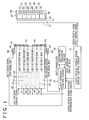
- a plan view and a vertical sectional view of the liquid crystal display apparatus are shown in a juxtaposed relationship with each other.
- a video signal or image signal inputted to the liquid crystal display apparatus is supplied to a liquid crystal display image display control circuit 11, which produces a signal for driving a liquid crystal display panel 12 to perform display action based on the video signal.
- the thus produced displaying driving signal is supplied to the liquid crystal display panel 12, in which a display signal is written into each of pixels disposed on the liquid crystal display panel 12.
- the writing of the display signal is performed, for example, in a period of one frame in synchronism with a frame period of the video signal supplied thereto.
- a backlight 20 is disposed on the back of the liquid crystal display panel 12.
- the backlight 20 includes cold cathode fluorescent lamps 21, 22, 23, 24, 25 and 26 as light sources juxtaposed in a vertical column and each extending in a horizontal direction.
- the backlight is configured such that the cold cathode fluorescent lamps 21 to 26 thereof are disposed in a vertical column in a light box 29 which forms the backlight 20.
- a reflection sheet 28 is disposed on the back side of the cold cathode fluorescent lamps 21 to 26.
- a diffusion plate 14 is disposed on the front of the light box 29 in which the cold cathode fluorescent lamps 21 to 26 are disposed.
- the diffusion plate 14 has a size substantially equal to the display area of the liquid crystal display panel 12 and is formed, for example, from an acrylic sheet or plate so that it diffuses light.
- partition plates 31 to 35 are disposed between adjacent ones of the cold cathode fluorescent lamps 21 to 26 in the light box 29 so that light flexes from the cold cathode fluorescent lamps 21 to 26 may be introduced to the diffusion plate 14 without mixing with light fluxes from other adjacent lamps.
- Lighting or turning on/off of the cold cathode fluorescent lamps 21 to 26 is controlled by light emission control signals supplied individually to the cold cathode fluorescent lamps 21 to 26 from a light emission control circuit 15.
- a vertical synchronizing signal VS and a horizontal synchronizing signal HS of the video signal are supplied from the liquid crystal display image display control circuit 11 to the light emission control circuit 15 so that the light emission control circuit 15 performs a temporary turning off process successively for the cold cathode fluorescent lamps 21 to 26.
- the position at which one of the cold cathode fluorescent lamps 21 to 26 is turned off to emit no light and the position of a horizontal line in which writing into pixels of the liquid crystal display panel 12 disposed in front of that one of the cold cathode fluorescent lamps 21 to 26 which is turned off is performed coincide with each other.
- a blinking process described hereinabove in the description of the background of the invention is performed.
- two light guiding members 41 and 42 are disposed at the right end of the light box 29 so that light fluxes entering the light guiding members 41 and 42 from the locations of the cold cathode fluorescent lamps 21 to 26 are introduced to photo-sensors 43 and 46 attached to the light guiding members 41 and 42, respectively.
- the light guiding members 41 and 42 are made of a transparent material such as, for example, an acrylic resin material.
- the light guiding members 41 and 42 are described more particularly.
- the locations of the fluorescent lamp 21 in the first row, fluorescent lamp 22 in the second row and fluorescent lamp 23 in the third row disposed in order from above are selected such that light fluxes from the fluorescent lamps 21, 22 and 23 are introduced into the first light guiding member 41 at the right end of the light box 29 and then introduced to the photo-sensor 43 on a board 44 provided at an upper end of the backlight 20.
- the first light guiding member 41 is shaped such that it reflects the light fluxes from the fluorescent lamps 21, 22 and 23 at different angles from one another in order to introduce the light fluxes into the single photo-sensor 43.
- the light paths in this instance are individually indicated by arrow marks in FIG. 1.
- the locations of the fluorescent lamp 24 in the fourth row, fluorescent lamp 25 in the fifth row and fluorescent lamp 26 in the sixth row are selected such that light fluxes from the fluorescent lamps 24, 25 and 26 are introduced into the second light guiding member 42 at the right end of the light box 29 and then introduced into the single photo-sensor 46 on a board 47 provided at a lower end of the backlight 20.
- the second light guiding member 42 is shaped such that it reflects the light fluxes from the fluorescent lamps 24, 25 and 26 at different angles from one another in order to introduce the light fluxes into the single photo-sensor 46.
- the light paths in this instance are individually indicated by arrow marks in FIG. 1.
- the photo-sensors 43 and 46 are configured so as to output a voltage signal corresponding to the level of light incident thereto and each outputs a voltage signal of a level corresponding to the total of luminances of light arriving thereat from the respective three fluorescent lamps.
- the voltage signals outputted are converted into digital data by analog/digital converters 45 and 48 attached to the boards 44 and 47, respectively, and then sent to the light emission control circuit 15.
- the light emission control circuit 15 sends a digital conversion trigger pulse to the analog/digital converters 45 and 48, and data sampled at a timing indicated by the trigger pulse are sent to the light emission control circuit 15. An example of the timing for sampling is hereinafter described.
- An arithmetic operation circuit 16 is connected to the light emission control circuit 15 such that detection level data of the photo-sensors 43 and 46 supplied to the light emission control circuit 15 are supplied to the arithmetic operation circuit 16. Consequently, the arithmetic operation circuit 16 performs an arithmetic operation process of calculating the luminances of light emitted from the six cold cathode fluorescent lamps 21 to 26 by arithmetic operation using operational expressions set in advance.
- the operational expressions are hereinafter described.
- FIGS. 2A to 2F an example of a corresponding relationship between a writing state of an image into the pixels disposed on the liquid crystal display panel of the display apparatus of the present embodiment and a lighting state of the backlight is described with reference to FIGS. 2A to 2F.
- writing of an image into the liquid crystal panel is performed in a unit of a horizontal line
- FIGS. 2A to 2F illustrate different writing positions of the image which successively change in order.
- the right half illustrates an image writing state into the liquid crystal display panel
- the left half illustrates light emitting and no-light emitting positions of the backlight.
- 2A to 2F signifies an image of the last frame, and the new image signifies an image of a current frame.
- two fluorescent lamps in the proximity of the position at which an image signal is written into pixels in the current frame, that is, the position of the boundary between an old image and a new image, are turned off to emit not light while the remaining four fluorescent lamps are turned on to emit light.
- FIGS. 2A to 2F are investigated more particularly.
- the position at which an image signal is written is positioned at a lower portion of the screen, and the two lowermost fluorescent lamps 25 and 26 from among the six fluorescent lamps are turned off to emit no light while the remaining four fluorescent lamps are turned on to emit light. If the writing position further moves downwardly from this position, then the lowermost fluorescent lamp 26 and the uppermost fluorescent lamp 21 are turned off and emit no light as seen in FIG. 2B. Then, if the writing position comes the top of the screen, then the two uppermost fluorescent lamps 21 and 22 are turned off and emit no light as seen in FIG. 2C. If the writing position thereafter successively moves downwardly from this position, then the turning off position of two fluorescent lamps successively moves downwardly as seen in FIGS. 2D, 2E and 2F. The transition illustrated in FIGS. 2A to 2F is repeated for every one frame.
- first to sixth light emission states wherein the combination of two fluorescent lamps are turned off from among the six fluorescent lamps as seen in FIGS. 3A, 3B, 3C, 3D, 3E and 3F, respectively, are defined
- detection is preformed once by each of the photo-sensor 43 and the photo-sensor 46 in each of the light emission states.
- the light emission states are defined as seen in FIGS. 3A to 3F
- if two photo-sensor outputs are successively detected within the first to sixth light emission states then such a state as seen in FIG. 4A is obtained.
- FIG. 4A the upper photo-sensor denotes an output of the photo-sensor 43 while the lower photo-sensor denotes an output of the photo-sensor 46.
- FIG. 4B illustrates a vertical synchronizing pulse of the display image. As seen in FIG. 4B, a pulse appears immediately prior to the first light emission state.
- FIG. 4A the outputs of the two photo-sensors 43 and 46 repeat a variation in response to the variation of the position at which fluorescent lamps are turned off.
- FIG. 4C indicates a trigger pulse to be used for sampling of the output of the photo-sensor 43 while
- FIG. 4D illustrates a trigger pulse to be used for sampling of the output of the-photo-sensor 46.
- the output of the photo-sensor 43 is fetched in the first to third states, and the output of the photo-sensor 46 is fetched in the fourth to sixth states.
- the sensor outputs fetched in the first to sixth light emission states are represented as signals S1 to S6, respectively.
- This arithmetic operation process is executed by the arithmetic operation circuit 16 shown in FIG. 1.
- Data of individual emitted light luminances of the six fluorescent lamps 21 to 26 obtained by the arithmetic operation circuit 16 are sent to the light emission control circuit 15.
- the light emission control circuit 15 performs a process of correcting the emitted light luminances of the fluorescent lamps 21 to 26 based on the data of the emitted light luminances.
- the correction process for each emitted light luminance is performed, for example, by control of the voltage to be applied to the corresponding fluorescent lamp.
- the emitted light luminances of the six fluorescent lamps 21 to 26 can always be corrected to a uniform level. For example, even if some variation of the environment of use or a secular change occurs, an uniform emitted light condition can always be assured, and appearance of unevenness in brightness of the image displayed through illumination by the backlight can be prevented.
- the liquid crystal display apparatus of the present embodiment since the liquid crystal display apparatus of the present embodiment includes only two light guiding members 41 and 42 and two photo-sensors 43 and 46, it has a configuration simpler than that in an alternative case wherein a photo-sensor is provided for each of six light sources. Consequently, the cost demanded for production of a backlight can be reduced.
- the liquid crystal display apparatus of the present embodiment is a modification to and has a generally similar configuration to that of the liquid crystal display apparatus of the first embodiment described hereinabove with reference to FIGS. 1 to 4D. Therefore, in the following description, only differences of the liquid crystal display apparatus of the present embodiment from those of the first embodiment are described.
- the liquid crystal display apparatus of the present embodiment is generally configured such that it includes a single photo-sensor such that the luminance of all light sources is detected by the single photo-sensor and the luminances of the light sources are determined from detection outputs at different timings from the single photo-sensor.
- a light guiding member 51 for guiding light from the six cold cathode fluorescent lamps 21 to 26 to a single photo-sensor 53 is disposed at the right end of the backlight 20 in which the cold cathode fluorescent lamps 21 to 26 are disposed such that the photo-sensor 53 detects the total of outputs of the cold cathode fluorescent lamps 21 to 26.
- the light guiding member 51 may be made of, for example, n acrylic resin material.
- the liquid crystal display apparatus further includes a reflecting mirror 52 disposed for reflecting light directed toward the center by the light guiding member 51 so as to be inputted to the photo-sensor 53.
- the photo-sensor 53 is attached to a board 54 and fetches a signal as digital data from an analog/digital converter 55 attached to the board 54. The digital data are sent to the light emission control circuit 15.
- the emitted light amount data sent from the photo-sensor 53 are sent to an arithmetic operation circuit 16', and the emitted light amounts of the cold cathode fluorescent lamps 21 to 26 are calculated from the received emitted light amount data by arithmetic operation of the arithmetic operation circuit 16'.
- the liquid crystal display apparatus shown in FIG. 5 includes a single photo-sensor, it is necessary to change the light emission pattern and the operational expressions of the lamps from those of the liquid crystal display apparatus shown in FIGS. I to 4D. Where the configuration shown in FIG. 5 is employed, the number of photo-sensors can be reduced to one, and consequently, a more simplified configuration can be achieved.
- the liquid crystal display apparatus of the present embodiment is a modification to and has a generally similar configuration to that of the liquid crystal display apparatus of the second embodiment described hereinabove with reference to FIG. 5. Therefore, in the following description, only differences of the liquid crystal display apparatus of the present embodiment from those of the second embodiment are described.
- the liquid crystal display apparatus according to the third embodiment shown is generally configured such that the light guiding member has a more simplified configuration.
- the light guiding member in the first and second embodiments shown in FIGS. 1 and 4 is configured such that it is made of an acrylic resin material or the like and guides light.
- the light guiding member in the present embodiment is configured such that it has a form of a reflection sheet disposed in the light box which is a component of the backlight and inputs light to one or two photo-sensors.
- a light guiding light guiding hollow member 61 is disposed at the right end of the light box 29, and a reflection element is disposed on an inner wall of the light guiding hollow member 61.
- a reflecting mirror 62 is disposed at a central portion of the reflecting member so that light reflected by the reflecting mirror 62 is introduced into a photo-sensor 63.
- the photo-sensor 63 is attached to a board 64, and an output of the photo-sensor 63 is converted into digital data by an analog/digital converter 65 and supplied to the light emission control circuit 15 side.
- liquid crystal display apparatus is configured in such a manner as described above, the necessity for a light guiding member of an acrylic resin material or the like is eliminated, and a simpler light guiding configuration can be achieved.
- liquid crystal display apparatus according to a fourth embodiment of the present invention is described with reference to FIG. 7.
- the liquid crystal display apparatus of the present embodiment is a modification to and has a generally similar configuration to that of the liquid crystal display apparatus of the first embodiment described hereinabove with reference to FIGS. 1 to 4D. Therefore, in the following description, only differences of the liquid crystal display apparatus of the present embodiment from those of the first embodiment are described.
- the liquid crystal display apparatus of the present embodiment uses a light emitting diode for the light sources.
- a backlight 70 disposed on the back of the liquid crystal display panel 12 includes red light emitting diodes 71R to 76R, green light emitting diodes 71G to 76G and blue light emitting diodes 71B to 76B disposed in order in individual rows.
- a light box 79 is configured such that the inside of a reflecting sheet 78 is partitioned into six portions in the vertical direction by partition plates 31 to 35 similarly as in the light box 29 shown in FIG. 1. In each of the partitions which are rows as seen in FIG. 7, red light emitting diodes, green light emitting diodes and blue light emitting diodes are disposed in order.
- a demanded number of red light emitting diodes 71R, green light emitting diodes 71G and blue light emitting diodes 71B are disposed in a row in a horizontal direction in the top one of the sections in the light box 79, that is, in the first row.
- a demanded number of red light emitting diodes 72R, green light emitting diodes 72G and blue light emitting diodes 72B are disposed in a row.
- a demanded number of red light emitting diodes 73R, green light emitting diodes 73G and blue light emitting diodes 73B are disposed in a row.
- a demanded number of red light emitting diodes 74R, green light emitting diodes 74G and blue light emitting diodes 74B are disposed in a row.
- a demanded number of red light emitting diodes 75R, green light emitting diodes 75G and blue light emitting diodes 75B are disposed in a row.
- a demanded number of red light emitting diodes 76R, green light emitting diodes 76G and blue light emitting diodes 76B are disposed in a row.
- Two light guiding members 41 and 42 are disposed at the right end of the light box 79 such that light introduced into the light guiding members 41 and 42 from the locations of the light emitting diodes is introduced into the photo-sensors 43 and 46 attached to the light guiding members 41 and 42, respectively.
- the light guiding members 41 and 42 are made of a transparent material such as, for example, an acrylic resin material.
- the light guiding members 41 and 42 are described more particularly.
- the light emitting diodes 71R, 71G and 71B in the first row, light emitting diodes 72R, 72G and 72B in the second row and light emitting diodes 73R, 73G and 73B in the third row in order from above are located such that light therefrom is introduced to the first light guiding member 41 at the right end of the light box 79 so that it is introduced into the photo-sensor 43 on the board 44 attached to an upper end of the backlight 70.
- the first light guiding member 41 is shaped such that, in order to introduce light fluxes from the light emitting diodes in the first, second and third rows to the single photo-sensor 43, it reflects the light fluxes at different angles from one another.
- the light emitting diodes 74R, 74G and 74B in the fourth row, light emitting diodes 75R, 75G and 75B in the fifth row and light emitting diodes 76R, 76G and 76B in the sixth row are located such that light therefrom is introduced to the second light guiding member 42 at the right end of the light box 79 so that it is introduced into the photo-sensor 46 on the board 47 attached to a lower end of the backlight 70.
- the second light guiding member 42 is shaped such that, in order to introduce light fluxes from the light emitting diodes in the fourth, fifth and sixth rows to the single photo-sensor 46, it reflects the light fluxes at different angles from one another.
- the photo-sensors 43 and 46 are configured so as to output a voltage signal corresponding to the level of light incident thereto.
- each of the photo-sensors 43 and 46 outputs a voltage signal of a level corresponding to the total of luminances of light fluxes arriving thereat from the light emitting diodes of the corresponding three rows.
- the voltage signal outputted from the photo-sensor 43 or 46 is converted into digital data by an analog/digital converter 45 or 48 attached to the board 44 or 47 and then sent to a light emission control circuit 15'.
- the light emission control circuit 15' sends a digital conversion trigger pulse to the analog/digital converters 45 and 48. Consequently, data sampled at a timing indicated by the trigger pulse are sent to the light emission control circuit 15'.
- An arithmetic operation circuit 16" is connected to the light emission control circuit 15' such that detection level data of the photo-sensors 43 and 46 supplied to the light emission control circuit 15' are supplied to the arithmetic operation circuit 16".
- the arithmetic operation circuit 16" thus performs an arithmetic operation process of calculating emitted light luminances of the light emitting diodes in the six rows by arithmetic operation in which operational expressions set in advance are used. To the operational expressions, those given hereinabove in the description of the first embodiment can be applied.
- the liquid crystal display apparatus of the present embodiment is configured in such a manner as described above, similar emitted light luminance control of light sources can be applied also where a light emitting diode is used for the light sources, and similar good image display can be anticipated. It is to be noted that, while the numbers of red light emitting diodes; green light emitting diodes and blue light emitting diodes in the arrangement of FIG. 7 are equal to one another, different numbers of red, green and blue light emitting diodes may be disposed in response to emitted light luminance characteristics of the light emitting diodes so that white backlight light may be obtained.
- each of the photo-sensors 43 and 46 is formed as a sensor for detecting the luminance, and a process of correcting the emitted light luminance of the light source is performed based on an output of the sensor.
- each of the photo-sensors 43 and 46 may otherwise detect the chromaticity. Where the chromaticity is detected by the photo-sensors 43 and 46 in this manner, the emitted light amounts of the light emitting diodes of the colors are controlled in response to detection values of the chromaticity to perform correction of the chromaticity, that is, to correct the offset from the white. Where correction of the color is performed in this manner, better backlight light is obtained.
- control of the emitted light amount of the light emitting diodes may be, for example, control of the amount of current to be supplied to the light emitting diodes or control of the period of time within which current is supplied to the light emitting diodes.
- the chromaticity of the fluorescent lamps may be decided such that the emitted light colors of the light sources are corrected individually based on the decision.
- a cathode ray fluorescent lamp or a light emitting diode is used as a light source
- some other light source such as a hot cathode fluorescent lamp may be used such that the luminance or the chromaticity of the light source is corrected.
- a light emitting diode for example, a light emitting diode which emits white light may be used.
- the present invention can be applied also where a plurality of different types of light sources such as a cold cathode fluorescent lamp and a light emitting diode are used in combination.
- a light source is divided into six light sources in the vertical direction.
- the light source may be divided also into a plurality of light sources in the horizontal direction and hence into a matrix.
- the luminance of the light sources is detected and corrected using a limited number of photo-sensors.
- the present invention is applied to a backlight configured such that a partitioning member or partition plate is disposed between adjacent ones of light sources.
- the present invention can be applied also to another backlight apparatus which includes no partitioning member and allows light fluxes from adjacent light sources to mix with each other. In this instance, however, it is necessary to decide the luminance or the like of each light source taking also the influence of light from an adjacent light source into consideration.
Applications Claiming Priority (2)
| Application Number | Priority Date | Filing Date | Title |
|---|---|---|---|
| JP2005303405 | 2005-10-18 | ||
| JP2006223378A JP4497140B2 (ja) | 2005-10-18 | 2006-08-18 | バックライト、表示装置及び光源制御方法 |
Publications (2)
| Publication Number | Publication Date |
|---|---|
| EP1777693A2 true EP1777693A2 (fr) | 2007-04-25 |
| EP1777693A3 EP1777693A3 (fr) | 2007-12-05 |
Family
ID=37700906
Family Applications (1)
| Application Number | Title | Priority Date | Filing Date |
|---|---|---|---|
| EP06255351A Withdrawn EP1777693A3 (fr) | 2005-10-18 | 2006-10-18 | Dispositif de rétroéclairage et méthode de contrôle de la source lumineuse |
Country Status (5)
| Country | Link |
|---|---|
| US (1) | US8085238B2 (fr) |
| EP (1) | EP1777693A3 (fr) |
| JP (1) | JP4497140B2 (fr) |
| KR (1) | KR20070042473A (fr) |
| TW (1) | TWI351552B (fr) |
Cited By (3)
| Publication number | Priority date | Publication date | Assignee | Title |
|---|---|---|---|---|
| EP1705636A1 (fr) | 2005-03-24 | 2006-09-27 | Sony Corporation | Appareil et procédé d'affichage |
| WO2010066134A1 (fr) * | 2008-12-09 | 2010-06-17 | 光远科技股份有限公司 | Procédé de compensation d'uniformité pour lcd muni d'une plaque de rétro-éclairage irrégulière et affichage associé |
| RU2461075C2 (ru) * | 2007-04-26 | 2012-09-10 | Сони Корпорейшн | Схема регулирования дисплея для панели органической электролюминесценции, схема регулирования дисплея и устройство дисплея |
Families Citing this family (22)
| Publication number | Priority date | Publication date | Assignee | Title |
|---|---|---|---|---|
| JP4628770B2 (ja) * | 2004-02-09 | 2011-02-09 | 株式会社日立製作所 | 照明装置を備えた画像表示装置及び画像表示方法 |
| WO2008023542A1 (fr) * | 2006-08-23 | 2008-02-28 | Nippon Seiki Co., Ltd. | Dispositif d'affichage à cristaux liquides |
| US20100188443A1 (en) * | 2007-01-19 | 2010-07-29 | Pixtronix, Inc | Sensor-based feedback for display apparatus |
| JP4980749B2 (ja) * | 2007-02-28 | 2012-07-18 | シャープ株式会社 | 表示装置 |
| JP5510859B2 (ja) * | 2007-03-30 | 2014-06-04 | Nltテクノロジー株式会社 | バックライト装置および液晶表示装置 |
| JP2008268642A (ja) * | 2007-04-23 | 2008-11-06 | Sony Corp | バックライト装置、バックライト制御方法、および液晶表示装置 |
| WO2011045671A2 (fr) * | 2009-10-14 | 2011-04-21 | Energy Micro AS | Circuit d'attaque d'écran à cristaux liquides |
| WO2011064870A1 (fr) * | 2009-11-26 | 2011-06-03 | キヤノン株式会社 | Procédé de commande pour un écran d'affichage, et écran d'affichage |
| US8749538B2 (en) | 2011-10-21 | 2014-06-10 | Qualcomm Mems Technologies, Inc. | Device and method of controlling brightness of a display based on ambient lighting conditions |
| JP6099884B2 (ja) * | 2012-05-25 | 2017-03-22 | 三菱電機株式会社 | 立体画像表示装置 |
| US9684121B2 (en) * | 2012-07-27 | 2017-06-20 | Shenzhen China Star Optoelectronics Technology Co., Ltd | Side-edge backlight module having non-uniformly sized backlight sections and design method thereof |
| US9183812B2 (en) | 2013-01-29 | 2015-11-10 | Pixtronix, Inc. | Ambient light aware display apparatus |
| CN104023453B (zh) * | 2014-06-23 | 2016-09-14 | 银川博聚工业产品设计有限公司 | 一种发射光源控制电路 |
| CN108025541B (zh) | 2016-03-19 | 2021-01-15 | 三菱化学株式会社 | 涂布膜 |
| US10032418B2 (en) * | 2016-05-09 | 2018-07-24 | Japan Display Inc. | Display apparatus |
| CN107833566B (zh) * | 2017-09-30 | 2019-11-22 | 明基智能科技(上海)有限公司 | 调整显示影像长宽比例的方法以及显示系统 |
| CN110017895B (zh) * | 2019-03-26 | 2023-11-14 | 广州市轩士佳电子科技有限公司 | 一种光源监控系统 |
| US11030944B1 (en) * | 2019-12-04 | 2021-06-08 | Capital One Services, Llc | Systems and methods for correcting ambient-light illuminance differences of ambient light directed onto regions of a display |
| CN115023750B (zh) * | 2020-02-21 | 2023-08-15 | Eizo株式会社 | 显示画面的射出光的检测方法以及显示装置 |
| US11776503B2 (en) * | 2020-05-28 | 2023-10-03 | Apple Inc. | Generating display data based on modified ambient light luminance values |
| CN112767878B (zh) * | 2021-01-29 | 2022-09-23 | 昆山国显光电有限公司 | 亮度调节方法、装置及显示设备 |
| CN112947792A (zh) * | 2021-03-30 | 2021-06-11 | 维沃移动通信有限公司 | 显示模组、电子设备及其控制方法和控制装置 |
Citations (6)
| Publication number | Priority date | Publication date | Assignee | Title |
|---|---|---|---|---|
| US6069676A (en) | 1996-08-02 | 2000-05-30 | Citizen Electronics Co., Ltd. | Sequential color display device |
| US20030016205A1 (en) | 2001-07-19 | 2003-01-23 | Masae Kawabata | Lighting unit and liquid crystal display device including the lighting unit |
| WO2003077013A2 (fr) | 2002-03-13 | 2003-09-18 | The University Of British Columbia | Dispositifs d'affichage a plage dynamique elevee |
| EP1482770A1 (fr) | 2002-03-01 | 2004-12-01 | Sharp Kabushiki Kaisha | Dispositif emetteur lumiere et affichage utilisant ce dispositif et dispositif de lecture |
| JP2005208486A (ja) | 2004-01-26 | 2005-08-04 | Hitachi Ltd | 液晶表示装置 |
| US20050180681A1 (en) * | 2002-03-15 | 2005-08-18 | Hitachi Maxell, Ltd. | Optical communication device and laminated optical communication module |
Family Cites Families (11)
| Publication number | Priority date | Publication date | Assignee | Title |
|---|---|---|---|---|
| JP2000275604A (ja) | 1999-03-23 | 2000-10-06 | Hitachi Ltd | 液晶表示装置 |
| JP2001318614A (ja) | 2000-05-09 | 2001-11-16 | Mitsubishi Electric Corp | 面光源装置及びこれを用いた液晶表示装置 |
| JP3699002B2 (ja) | 2000-06-15 | 2005-09-28 | シャープ株式会社 | 液晶表示装置および液晶表示装置の駆動方法 |
| JP3971892B2 (ja) * | 2000-09-08 | 2007-09-05 | 株式会社日立製作所 | 液晶表示装置 |
| JP2003050569A (ja) | 2000-11-30 | 2003-02-21 | Hitachi Ltd | 液晶表示装置 |
| JP4253292B2 (ja) * | 2002-03-01 | 2009-04-08 | シャープ株式会社 | 発光装置並びに該発光装置を用いた表示装置及び読み取り装置 |
| KR100868159B1 (ko) * | 2002-10-29 | 2008-11-12 | 샤프 가부시키가이샤 | 조명 장치 및 그것을 이용한 액정 표시 장치 |
| US7202850B2 (en) * | 2002-11-26 | 2007-04-10 | Matsushita Electric Industrial Co., Ltd. | Image display control apparatus and image display control method |
| JP2004275604A (ja) | 2003-03-18 | 2004-10-07 | Mitsubishi Motors Corp | 車両用シート構造 |
| TW594257B (en) * | 2003-05-23 | 2004-06-21 | Au Optronics Corp | Direct-type backlight module having photo sensors |
| JP3813144B2 (ja) | 2003-09-12 | 2006-08-23 | ローム株式会社 | 発光制御回路 |
-
2006
- 2006-08-18 JP JP2006223378A patent/JP4497140B2/ja not_active Expired - Fee Related
- 2006-10-13 TW TW095137735A patent/TWI351552B/zh not_active IP Right Cessation
- 2006-10-16 US US11/581,667 patent/US8085238B2/en not_active Expired - Fee Related
- 2006-10-17 KR KR1020060100743A patent/KR20070042473A/ko active IP Right Grant
- 2006-10-18 EP EP06255351A patent/EP1777693A3/fr not_active Withdrawn
Patent Citations (6)
| Publication number | Priority date | Publication date | Assignee | Title |
|---|---|---|---|---|
| US6069676A (en) | 1996-08-02 | 2000-05-30 | Citizen Electronics Co., Ltd. | Sequential color display device |
| US20030016205A1 (en) | 2001-07-19 | 2003-01-23 | Masae Kawabata | Lighting unit and liquid crystal display device including the lighting unit |
| EP1482770A1 (fr) | 2002-03-01 | 2004-12-01 | Sharp Kabushiki Kaisha | Dispositif emetteur lumiere et affichage utilisant ce dispositif et dispositif de lecture |
| WO2003077013A2 (fr) | 2002-03-13 | 2003-09-18 | The University Of British Columbia | Dispositifs d'affichage a plage dynamique elevee |
| US20050180681A1 (en) * | 2002-03-15 | 2005-08-18 | Hitachi Maxell, Ltd. | Optical communication device and laminated optical communication module |
| JP2005208486A (ja) | 2004-01-26 | 2005-08-04 | Hitachi Ltd | 液晶表示装置 |
Cited By (4)
| Publication number | Priority date | Publication date | Assignee | Title |
|---|---|---|---|---|
| EP1705636A1 (fr) | 2005-03-24 | 2006-09-27 | Sony Corporation | Appareil et procédé d'affichage |
| US8264447B2 (en) | 2005-03-24 | 2012-09-11 | Sony Corporation | Display apparatus and method for controlling a backlight with multiple light sources of a display unit |
| RU2461075C2 (ru) * | 2007-04-26 | 2012-09-10 | Сони Корпорейшн | Схема регулирования дисплея для панели органической электролюминесценции, схема регулирования дисплея и устройство дисплея |
| WO2010066134A1 (fr) * | 2008-12-09 | 2010-06-17 | 光远科技股份有限公司 | Procédé de compensation d'uniformité pour lcd muni d'une plaque de rétro-éclairage irrégulière et affichage associé |
Also Published As
| Publication number | Publication date |
|---|---|
| TW200719032A (en) | 2007-05-16 |
| EP1777693A3 (fr) | 2007-12-05 |
| JP4497140B2 (ja) | 2010-07-07 |
| US20070120765A1 (en) | 2007-05-31 |
| KR20070042473A (ko) | 2007-04-23 |
| TWI351552B (en) | 2011-11-01 |
| JP2007141813A (ja) | 2007-06-07 |
| US8085238B2 (en) | 2011-12-27 |
Similar Documents
| Publication | Publication Date | Title |
|---|---|---|
| EP1777693A2 (fr) | Dispositif de rétroéclairage et méthode de contrôle de la source lumineuse | |
| US8026893B2 (en) | Liquid crystal display device and apparatus and method for driving the same | |
| EP1722267B1 (fr) | Unité de rétroéclairage et affichage à cristaux liquides doté de celle-ci | |
| US7782283B2 (en) | Apparatus and method for driving liquid crystal display device | |
| US7591568B2 (en) | Point light source, backlight assembly having the same and display apparatus having the same | |
| US8248359B2 (en) | Display apparatus and driving method therefor | |
| EP2141687A1 (fr) | Appareil de rétro-éclairage, procédé de commande de rétro-éclairage, et dispositif d'affichage à cristaux liquides | |
| US20090278789A1 (en) | Scanning backlight color control | |
| US20020030449A1 (en) | Display device compensating for color irregurality between pixels | |
| EP0478186A2 (fr) | Dispositif d'affichage | |
| TWI534788B (zh) | 畫像顯示裝置 | |
| US20070024772A1 (en) | Display with sub-region backlighting | |
| US7654692B2 (en) | Spread illuminating apparatus | |
| JP2004191490A (ja) | 液晶表示装置 | |
| JP2005208425A (ja) | 液晶表示装置 | |
| EP2487404A1 (fr) | Module de source de lumière et appareil électronique le comportant | |
| KR20070103680A (ko) | 액정 표시 장치 조립체의 구동 방법 | |
| US10347194B2 (en) | Display device and method for driving same | |
| US20100002027A1 (en) | Display device and method | |
| JP2009516328A (ja) | バックライトの光源の分布及び駆動 | |
| US20100315446A1 (en) | Display device | |
| JP2010512556A (ja) | 液晶ディスプレイ装置及び液晶ディスプレイ装置を駆動する方法 | |
| JP4876680B2 (ja) | 液晶表示装置組立体の駆動方法 | |
| CN108022524B (zh) | 像素结构、显示屏以及调整显示屏亮度均匀性的方法 | |
| CN100435006C (zh) | 背光、显示设备和光源控制方法 |
Legal Events
| Date | Code | Title | Description |
|---|---|---|---|
| PUAI | Public reference made under article 153(3) epc to a published international application that has entered the european phase |
Free format text: ORIGINAL CODE: 0009012 |
|
| AK | Designated contracting states |
Kind code of ref document: A2 Designated state(s): AT BE BG CH CY CZ DE DK EE ES FI FR GB GR HU IE IS IT LI LT LU LV MC NL PL PT RO SE SI SK TR |
|
| AX | Request for extension of the european patent |
Extension state: AL BA HR MK YU |
|
| PUAL | Search report despatched |
Free format text: ORIGINAL CODE: 0009013 |
|
| AK | Designated contracting states |
Kind code of ref document: A3 Designated state(s): AT BE BG CH CY CZ DE DK EE ES FI FR GB GR HU IE IS IT LI LT LU LV MC NL PL PT RO SE SI SK TR |
|
| AX | Request for extension of the european patent |
Extension state: AL BA HR MK YU |
|
| 17P | Request for examination filed |
Effective date: 20080519 |
|
| 17Q | First examination report despatched |
Effective date: 20080620 |
|
| AKX | Designation fees paid |
Designated state(s): DE FR GB |
|
| APBK | Appeal reference recorded |
Free format text: ORIGINAL CODE: EPIDOSNREFNE |
|
| APBN | Date of receipt of notice of appeal recorded |
Free format text: ORIGINAL CODE: EPIDOSNNOA2E |
|
| APBR | Date of receipt of statement of grounds of appeal recorded |
Free format text: ORIGINAL CODE: EPIDOSNNOA3E |
|
| APAF | Appeal reference modified |
Free format text: ORIGINAL CODE: EPIDOSCREFNE |
|
| APBT | Appeal procedure closed |
Free format text: ORIGINAL CODE: EPIDOSNNOA9E |
|
| STAA | Information on the status of an ep patent application or granted ep patent |
Free format text: STATUS: THE APPLICATION IS DEEMED TO BE WITHDRAWN |
|
| 18D | Application deemed to be withdrawn |
Effective date: 20160503 |