EP1777125A2 - Fussgängerschutzvorrichtung und Verfahren zur Einstellung von Lastcharakteristiken der Vorrichtung - Google Patents
Fussgängerschutzvorrichtung und Verfahren zur Einstellung von Lastcharakteristiken der Vorrichtung Download PDFInfo
- Publication number
- EP1777125A2 EP1777125A2 EP06254508A EP06254508A EP1777125A2 EP 1777125 A2 EP1777125 A2 EP 1777125A2 EP 06254508 A EP06254508 A EP 06254508A EP 06254508 A EP06254508 A EP 06254508A EP 1777125 A2 EP1777125 A2 EP 1777125A2
- Authority
- EP
- European Patent Office
- Prior art keywords
- section
- vehicle
- plate
- leg
- pedestrian
- Prior art date
- Legal status (The legal status is an assumption and is not a legal conclusion. Google has not performed a legal analysis and makes no representation as to the accuracy of the status listed.)
- Granted
Links
Images


Classifications
-
- B—PERFORMING OPERATIONS; TRANSPORTING
- B60—VEHICLES IN GENERAL
- B60R—VEHICLES, VEHICLE FITTINGS, OR VEHICLE PARTS, NOT OTHERWISE PROVIDED FOR
- B60R21/00—Arrangements or fittings on vehicles for protecting or preventing injuries to occupants or pedestrians in case of accidents or other traffic risks
- B60R21/34—Protecting non-occupants of a vehicle, e.g. pedestrians
- B60R2021/343—Protecting non-occupants of a vehicle, e.g. pedestrians using deformable body panel, bodywork or components
Definitions
- the present invention relates to a pedestrian protection apparatus, and a method of tuning a load characteristic of the apparatus. More particularly, the present invention relates to an improved configuration of a pedestrian protection apparatus that is installed on a lower front side of a vehicle and that protects the legs of a pedestrian by sweeping the legs in contact with lower parts of the legs when the front of the vehicle collides with or comes into contact with the legs, and to a method of advantageously tuning a load characteristic of the apparatus.
- Various types of protection apparatuses are conventionally installed on front, rear, or side faces of vehicles, such as automobiles, mainly in order to absorb a shock energy caused in a collision and to thereby protect the body of the vehicles and passengers.
- apparatuses for protecting a pedestrian have been installed at the fronts of vehicles to protect the pedestrian when the front of the vehicles collide (comes into contact) with the pedestrian.
- a so-called leg sweep member is a known pedestrian protection apparatus.
- the leg sweep member is installed inside or below a front bumper independently, and applies a reaction force to an impact load, which is inputted in a collision between the pedestrian and the front of the vehicle, to the lower parts of the legs of the pedestrian so that the lower parts of the legs are swept away (tripped) and the pedestrian falls down onto the vehicle.
- This advantageously reduces the angle of forced bending of the knees in an undesirable direction caused by the collision, minimizes the occurrence of injuries such as a bone fracture of a knee, and achieves protection and safety of the pedestrian.
- JP-A-2001-277963 discloses a leg sweep member in which a resin foam member and a beam are mounted in the lower part of the front of a vehicle.
- the resin foam member extends in a width direction of the vehicle such that at least a part thereof protrudes from the front of the vehicle, and the beam extends in the width direction of the vehicle and is in contact with the rear side of the resin foam member.
- JP-A-2004-25976 discloses a leg sweep member that is formed of, for example, a metal pipe, and that is fixed to the lower part of the front of a vehicle such as to extend in the width direction of the vehicle.
- both the leg sweep members disclosed in the above publications have disadvantages to be overcome.
- the number of components is large. For this reason, the component cost is high, and it is troublesome to mount the apparatus.
- the weight thereof is inevitably high, and it is difficult to form the apparatus in a shape that conforms to the shape of the front of the vehicle.
- JP-A-2004-203183 proposes a pedestrian protection apparatus including a synthetic resin plate.
- the synthetic resin plate is fixed at a rear section to a vehicle such as to extend in the longitudinal direction of the vehicle and such that at least a portion of a front section thereof protrudes from the front of the vehicle.
- the projecting portion of the front section protruding from the front of the vehicle comes into contact with lower parts of the legs of the pedestrian, and sweeps the legs away.
- a plurality of flat ribs are disposed on one surface of the front section of the plate and formed in a lattice, and therefore, a high rigidity of the front section is ensured.
- a section of the plate other than the front section is shaped like a flat plate extending in the longitudinal direction of the vehicle with a sufficient length so that the front section can protrude from the front of the vehicle.
- the number of components is small.
- the plate which partly protrudes from the front of the vehicle, is formed of easily formable synthetic resin, the pedestrian can be protected while effectively overcoming the disadvantages of the apparatus including the resin foam member and the beam, and the apparatus formed of a metal pipe.
- the front section of the plate is highly rigid, it is prevented from being deformed by a shock caused by the contact with the legs of the pedestrian, or the amount of deformation is sufficiently reduced. Therefore, a reaction force to the impact load inputted to the plate efficiently acts on the legs of the pedestrian via the front section.
- the present inventors found that the maximum value of the impact load inputted when the front section of the synthetic resin plate in the above pedestrian protection apparatus collided with the legs of a pedestrian did sometimes not reach a target value, that a reaction force required to sweep the legs away in the collision could not be ensured in this case, and that protection of the legs was insufficient.
- the load characteristic is required to vary depending on the type of the vehicle, for example, to be optimized in accordance with the shape of the front of the vehicle and a shock-absorbing member of a front bumper mounted at the front of the vehicle together with the pedestrian protection apparatus so that a reaction force to an impact load applied in a collision between the legs of a pedestrian and the front of the vehicle sufficiently acts on the legs to reliably sweep the legs away, regardless of the type of the vehicle in which the apparatus is installed.
- it is difficult to tune the load characteristic so that it is difficult to optimize the same.
- the present inventors conducted a pedestrian collision test under the assumption that the front of a vehicle collided with the legs of the pedestrian.
- a test vehicle including the above-described known pedestrian protection apparatus having a synthetic resin plate was used.
- deformation of a front section of the plate having high rigidity was prevented, or the amount of deformation was minimized in a collision with the leg of the pedestrian, as described above.
- the plate since a remaining section of the plate other than the front section was shaped like a simple flat plate, and is relatively long in the longitudinal direction of the vehicle, the plate was bent (buckled) at a center portion in a length direction (longitudinal direction of the vehicle) corresponding to a shock-receiving direction, in which the shock is primarily applied to the apparatus. Furthermore, as for the load characteristic of the known apparatus, the pedestrian collision test also revealed that the amount of increase of the impact load per unit time in the early stage of the shock input was relatively small.
- the present inventors made the following assumption. That is, when the front section of the plate in the known apparatus comes into contact with the legs of the pedestrian, the remaining section of the plate other than the front section is bent in an approximate V-shape, and therefore, the pedestrian protection apparatus provides a load characteristic such that the impact load gently increases in the early stage of the shock input, that is, such that much time is required for the impact load to reach a target load. For this reason, the maximum value of the impact load sometimes does not reach the target value in the known pedestrian protection apparatus.
- the present inventors earnestly studied the relationship between deformation of the remaining section of the plate other than the front section having high rigidity, and the load characteristic.
- the present inventors found that the impact load could be rapidly increased in the early stage of the shock input in a collision between the front of the vehicle and the legs of the pedestrian by bending (buckling), by the input shock, the remaining section of the plate at two points spaced with a predetermined distance therebetween in the longitudinal direction corresponding to the shock-receiving direction (longitudinal direction of the vehicle) so that the plate is bent in an approximate S-shape or a staircase shape.
- the present inventors also found that the remaining section of the plate was deformed to be bent in an approximate S-shape or in a staircase form by the input shock when the remaining section included portions that had mutually different rigidities and that were arranged in a specific order.
- the present invention has been completed on the basis of the above findings.
- the principle of the present invention is to provide a pedestrian protection apparatus, which includes a synthetic resin plate mounted in a lower part of a front side of a vehicle and extending in a longitudinal direction of the vehicle.
- the plate includes a front section having at least a protruding portion protruding from the front side of the vehicle, a rear section fixed to the vehicle, and a center section provided between the front and rear sections.
- the protruding portion of the front section of the plate comes into contact with and sweeps away a lower part of a leg of a pedestrian to protect the leg when the front side of the vehicle collides with the leg.
- the front section of the plate is more rigid than the rear section, and the center section is less rigid than the front section and more rigid than the rear section.
- the front section of the synthetic resin plate extending in the longitudinal direction of the vehicle comes into contact with the leg of the pedestrian.
- the front section is more rigid than the other sections of the plate.
- the other sections include the rear section having the portion fixed to the vehicle and is less rigid than the other sections of the plate, and the center section which is more rigid than the rear section.
- a reaction force to the impact load inputted in a collision between the leg and the front of the vehicle sufficiently acts on the leg. This allows the leg to be reliably swept away and to be sufficiently protected at a higher level.
- the distance between the boundary portion between the center and rear sections, and the front adjacent portion on the front side of and adjacent to the portion of the rear section fixed to the vehicle in other words, the distance between the portions that are bent when a shock is inputted in a collision between the leg of the pedestrian and the front of the vehicle can be changed arbitrarily. Consequently, it is possible to adjust the amount of increase of the impact load in the early stage of the shock input. For example, the amount of increase of the impact load can be decreased by increasing the distance between the boundary portion and the front adjacent portion, and can be increased by decreasing the distance.
- the load characteristic can be arbitrarily changed by simply changing the dimension of the center section of the plate in the longitudinal direction of the vehicle. As a result, even when the required characteristic varies depending on the type of the vehicle in which the apparatus is installed, it is possible to easily correspond to the variation.
- the present invention is preferably practiced in at least the following features.
- a pedestrian protection apparatus for a vehicle comprising:
- the center section of the plate includes a plurality of areas having mutually different rigidities, and the areas extend over a full dimension of the vehicle in a transverse direction, adjoin in the longitudinal direction of the vehicle, and are arranged in decreasing order of the rigidities from a front side of the center section.
- the pedestrian protection apparatus according to the above feature (1) or (2), wherein a plurality of reinforcing ribs extending in the longitudinal direction of the vehicle are provided integrally with each of the front and center sections of the plate so as to be spaced in the transverse direction of the vehicle, and the front and center sections are more rigid than the rear section in which the reinforcing ribs are not provided, and wherein the number of the reinforcing ribs provided in the front section is larger than the number of the reinforcing ribs provided in the center section, and the interval between the reinforcing ribs of the front section in the transverse direction of the vehicle is shorter than the interval between the reinforcing ribs of the center section so that the front section is more rigid than the center section.
- the rigidities of the front section and the center section can be made different from each other without fixing separate members onto the front section and the center section. Consequently, the plate including the sections having different rigidities, and the entire device can be advantageously configured with a minimized number of components.
- a method of tuning a load characteristic of a pedestrian protection apparatus for a vehicle wherein the pedestrian protection apparatus comprises:
- the load characteristic can be easily tuned by arbitrarily changing the maximum value of the impact load by means of an extremely simple design change, that is, by simply changing the dimension of the center section of the plate in the longitudinal direction of the vehicle.
- the load characteristic of the pedestrian protection apparatus can be optimized easily and reliably.
- a reaction force to the impact load can sufficiently act on the leg, and the leg can be reliably swept away, regardless of the type of the vehicle in which the apparatus is installed.
- a method of tuning a load characteristic of a pedestrian protection apparatus for a vehicle wherein the pedestrian protection apparatus comprises:
- the flexural elastic constants and flexural strengths of the boundary portion and the front adjacent portion can be appropriately changed by an extremely simple design change, that is, by simply fixing the first reinforcing member and the second reinforcing member to the boundary portion and the front adjacent portion. Consequently, it is possible to arbitrarily change the maximum value of the impact load and to easily tune the load characteristic.
- the tuning method according to this feature can effectively achieve operations and advantages similar to those achieved by the above-described feature (6).
- the center section of the plate includes a plurality of areas having mutually different rigidities, and the areas extend over a full dimension of the vehicle in a transverse direction, adjoin in the longitudinal direction of the vehicle, and are arranged in decreasing order of the rigidities from a front side of the center section.
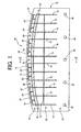
- FIGS. 1 and 2 are a top view and a cross-sectional view, respectively, schematically showing a leg sweep member 10 serving as a pedestrian protection apparatus according to a first embodiment of the present invention.
- the leg sweep member 10 of the first embodiment is installed inside a front bumper provided at the front of an automobile, and includes a base plate 12 serving as the plate, as shown in FIGS. 1 and 2.
- the base plate 12 is made of, for example, a synthetic resin material such as polypropylene or ABS resin, and is formed of a substantially rectangular thin plate.
- a dimension of the base plate 12 in the breadth direction in FIG. 1, which corresponds to the width or transverse direction of the automobile in which the leg sweep member 10 is installed (hereinafter referred to as the breadth direction) is smaller by a predetermined dimension than the width of the automobile, and a dimension thereof in the depth direction in FIG. 1, which corresponds to the longitudinal direction of the automobile (hereinafter referred to as the depth direction) is sufficiently smaller than the dimension in the breadth direction.
- the base plate 12 has an end curved surface 14 that is curved in accordance with the shape of an inner surface of the front bumper.
- the dimensions of the base plate 12 in the breadth and depth directions are appropriately determined, for example, depending on the width of the automobile in which the leg sweep member 10 is installed, and the size of the installation space.
- the dimension in the-depth direction is set at approximately 80 to 200 mm, and the thickness is generally set at approximately 3 mm.
- the first ribs 16 extend straight and rearward at a constant height from the side of the end curved surface 14.
- the first ribs 16 are arranged at regular intervals in the breadth direction.
- a third rib 18 shaped like a thin flat plate also protrudes integrally at almost the center in the depth direction on the upper surface of the base plate 12.
- the third rib 18 extends straight at a constant height over almost the full dimension of the base plate 12 in the breadth direction, and is combined with each of the first ribs 16 in the form of a cross.
- the interval between the first ribs 16 is, for example, approximately 25 mm.
- the height and thickness of the first ribs 16 are approximately 25 mm and approximately 3mm, respectively.
- the dimension of the first ribs 16 is about three-fourths of the dimension of the base plate 12 in the depth direction.
- the height and thickness of the third rib 18 are substantially equal to those of the first ribs 16.
- the fourth ribs 20 extend in the depth direction, and are arranged in line along the end curved surface 14.
- Each of the fourth ribs 20 connects front ends of some (three in the first embodiment) of the first ribs 16.
- the fourth ribs 20 are shaped like a thin flat plate, and the height and thickness thereof are substantially equal to those of the first ribs 16 and the third rib 18.
- a fifth rib 22 is provided a predetermined distance behind the fourth ribs 20 on the upper surface of the base plate 12.
- the fifth rib 22 projects at a predetermined height, and extends over almost the full dimension of the base plate 12 in the breadth direction. That is, at a position offset rearward from the end curved surface 14a of the base plate 12 by a distance corresponding to about one-fourth of the dimension of the base plate 12 in the depth direction, the fifth rib 22 extends across a front part of the base plate 12, and crosses all the first ribs 16.
- a front side face of the fifth rib 22 faces rear side faces of the fourth ribs 20 with a predetermined space therebetween.
- the fifth rib 22 is formed by bending a rear portion of the front part of the upper surface of the base plate 12 so that the fifth rib 22 is open downward and is angularly U-shaped in cross section.
- Second ribs 24 are provided integrally from the upper surface of the base plate 12 between the fourth ribs 20 and the fifth rib 22 that face each other.
- the second ribs 24 extend straight in the longitudinal direction from rear side faces of the fourth ribs 20 to a front side face of the fifth rib 22.
- Each of the second ribs 24 is provided approximately at the midpoint between the first longitudinal ribs 16 that are adjacent to each other in the breadth direction. That is, between the fourth ribs 20 and the fifth rib 22 that face each other on the upper surface of the base plate 12, front portions of the first ribs 16 and the second ribs 24 are arranged in the breadth direction at a short interval of approximately 12.5 mm that corresponds to half the interval between the first ribs 16.
- the second ribs 24 are each shaped like a thin flat plate, and have a height and a thickness substantially equal to those of the ribs 16, 18, and 20.
- first ribs 16, the second ribs 24, the fourth ribs 20, and the fifth rib 22 are provided integrally from a front section 26 of the base plate 12 so that the ribs are combined in a lattice form.
- the area of the front section 26 is about one-fourth of the total area of the upper surface of the base plate 12.
- the rigidity against a bending load that is, the deformation strength against an impact load inputted in the depth direction when the leg sweep member 10 is installed in the automobile, is sufficiently higher than that of the rear section 28 of the base plate 12 on which ribs are not provided.
- the first ribs 16 and the second ribs 24 serve as reinforcing ribs
- the third, fourth, and fifth ribs 18, 20, and 22 serve as auxiliary reinforcing ribs. Since the total dimension of the base plate 12 in the depth direction is generally approximately 80 to 200 mm, as described above, the dimensions (D 1 and D 3 in FIG. 2) in the depth direction of the front section 26 having the highest rigidity and the rear section 28 having the lowest rigidity are each approximately 15 to 50 mm, and the dimensions (D 2 in FIG. 2) in the depth direction of the center section 30, which is less rigid than the front section 26 and more rigid than the rear section 28, is approximately 50 to 100 mm.
- first auxiliary ribs 32 and a second auxiliary rib 34 are also provided on lower surfaces of the front section 26 and the center section 30 of the base plate 12.
- the first and second auxiliary ribs 32 and 34 are respectively positioned corresponding to the first ribs 16 and the third rib 18, and have structures substantially similar to those of the ribs 16 and 18.
- the number of the first auxiliary ribs 32 is the same as that of the first ribs 16. Therefore, the rigidities of the front section 26 and the center section 30 are further increased as a whole.
- Through-holes 36 and 38 are provided in a front end and side ends of the front section 26 of the base plate 12 and in a rear end of the rear section 28.
- the leg sweep member 10 having the above-described configuration is installed inside a front bumper 40 provided at the front of the automobile, for example, in a manner shown in FIG. 4.
- the front bumper 40 has a bumper cover 46 including an upper projecting portion 42 and a lower projecting portion 44 that protrude from the front of the automobile.
- the bumper cover 46 is disposed so that the upper projecting portion 42 is placed at a height such as to come into contact with the knee of a pedestrian when the bumper cover 46 collides with the pedestrian, and so that the lower projecting portion 44 is placed at a height such as to come into contact with a portion near the shank of the pedestrian (see FIG. 5).
- the bumper cover 46 is mounted, for example, by being fixed to a front grille 48, which forms a front face of the automobile, by bolts.
- reference numerals 50 and 51 denote a bonnet and a radiator, respectively.
- a bumper reinforcement 52 made of a rigid member is fixed inside the upper projecting portion 42 of the bumper cover 46 that is thus mounted at the front of the automobile (offset rearward from the front of the automobile).
- the bumper reinforcement 52 faces an inner surface of the upper projecting portion 42 with a predetermined space therebetween, and extends in the width direction of the automobile.
- a shock-absorbing member 54 is fixed to the bumper reinforcement 52 between the bumper reinforcement 52 and the upper projecting portion 42 of the bumper cover 46.
- the shock-absorbing member 54 is configured in a known manner, and has a thin resin body 56 that is shaped like a square pillar, which has a trapezoidal shape taken in a plane parallel to the impact-receiving direction and closed at one side, and is less rigid than the leg sweep member 10.
- the front section 26 of the base plate 12 in the leg sweep member 10 is disposed inside the lower projecting portion 44 of the bumper cover 46, and an upper surface of a rear portion of the rear section 28 is in contact with a lower surface of a radiator support 58 that extends in the widthwise direction of the automobile and is fixed to the front of the automobile so as to support the radiator 51.
- Resin clips 62 extending through an inward flange 60 integrally provided with a lower end of the lower projecting portion 44 are fitted in the corresponding through-holes 36 provided in the front end and the side ends of the front section 26 of the base plate 12, and the front section 26 is thereby fixed to the inward flange 60.
- each of fixing bolts 64 are fitted in the corresponding one of through-holes 38 at the rear end of the rear section 28, and the rear section 28 is thereby fixed to the radiator support 58.
- the leg sweep member 10 horizontally extends in the longitudinal direction of the automobile inside the lower projecting portion 44 of the bumper cover 46, and connects the lower projecting portion 44 and the radiator support 58 while the front section 26 of the base plate 12 protrudes from the front of the automobile.
- the fixing manner is not limited thereto, and other known fixing structures may be adopted appropriately.
- the front section 26 does not always need to be fixed to the bumper cover 46.
- the upper projecting portion 42 and the lower projecting portion 44 of the bumper cover 46 are deformed (displaced) toward the rear of the automobile by a shock due to the contact with portions of the leg portion 66 near a knee 68 and a shank 70, and the shock-absorbing member 54 and the leg sweep member 10 respectively provided inside the upper and lower projecting portions 42 and 44 are also deformed (displaced) rearward.
- the shock-absorbing member 54 (resin body 56) is less rigid than the leg sweep member 10
- the shock-absorbing member 54 is deformed more than the leg sweep member 10.
- the lower projecting portion 44 of the bumper cover 46 protrudes more from the front of the automobile than the upper projecting portion 42, and a reaction force to an impact load caused by the collision between the leg portion 66 and the bumper cover 46 acts the portion of the leg portion 66 near the shank 70 via the lower projecting portion 44.
- the portion of the leg portion 66 near the shank 70 is swept away (tripped) by the leg sweep member 10 so that the pedestrian falls down onto the bonnet 50 of the automobile. This reduces bending of the knee 68 of the pedestrian in an undesired direction, and minimizes injury, such as bone fracture, of the knee 68. In this way, protection and safety of the pedestrian are achieved effectively.
- the base plate 12 is bent (buckled) at two positions, namely, at the boundary portion 72 and the front adjacent portion 74.
- overall the base plate 12 (leg sweep member 10) is deformed in an approximate S-shape or a staircase shape.
- the bumper cover 46 collides with the leg portion 66 of the pedestrian, a sufficient reaction force to the inputted impact load acts on the leg portion 66, and the leg portion 66 is reliably swept away. Therefore, the leg portion 66 is reliably protected at a higher level.
- the base plate 12 is bent at two positions, that is, at the boundary portion 72 between the center and rear sections 30, 28, and the front adjacent portion 74 provided on the front side of and adjacent to the portion of the rear section 28 fixed to the radiator support 58. Therefore, the impact load inputted to the entire leg sweep member 10 is rapidly increased in the early stage of the input.
- the maximum value of the impact load greatly depends on the flexural rigidities of the boundary portion 72 and the front adjacent portion 74 of the base plate 12. That is, the maximum value of the impact load is large when the flexural rigidities of the boundary portion 72 and the front adjacent portion 74 are high, and is small when the flexural rigidities are low.
- FIG. 6 shows a leg sweep member 10 according to a second embodiment of the present invention.
- the distance D 4 between the boundary portion 72 and the front adjacent portion 74 is increased by decreasing the dimension D 2 of the center section 30 of the base plate 12 in the depth direction and increasing the dimension D 3 of the rear section 28 in the depth direction without changing the dimension D 1 of the front section 26 of the base plate 12 in the depth direction.
- the bumper cover 46 collides with the leg portion 66 of the pedestrian, the base plate 12 is easily bent at the boundary portion 72 and the front adjacent portion 74 on the principle of leverage, as shown in FIG. 7. Consequently, the maximum value of an impact load inputted in a collision between the leg portion 66 and the bumper cover 46 can be favorably made small.
- leg sweep member 10 shown in FIGS. 6 and 7, and leg sweep members shown in FIGS. 8 to 11, which will be described below, similar to those of the leg sweep member 10 shown in FIGS. 1 to 5 are denoted by the same reference numerals, and detailed descriptions thereof are omitted.
- the maximum value of the impact load can be arbitrarily changed and the load characteristic can be easily tuned by an extremely simple design change, that is, by simply increasing or decreasing the dimension of the center section 30 of the base plate 12 in the depth direction.
- FIG. 8 shows a leg sweep member 10 according to a third embodiment of the present invention.
- the dimensions D 1 , D 2 , and D 3 of the front section 26, the center section 30, and the rear section 28 of the base plate 12 in the longitudinal direction are not changed, and a reinforcing plate 76 having a predetermined flexural rigidity and made of synthetic resin is fixed to an upper or lower surface of the base plate 12 so as to extend over the boundary portion 72 and the front adjacent portion 74.
- the flexural rigidities of the boundary portion 72 and the front adjacent portion 74 are made higher than when the reinforcing plate 76 is not fixed. Therefore, the maximum value of the impact load inputted by a collision between the leg portion 66 of the pedestrian and the bumper cover 46 can be effectively increased, depending on the flexural rigidity of the reinforcing plate 76.
- the reinforcing plate 76 forms a first reinforcing member and a second reinforcing member.
- the base plate 12 is, of course, structured so that the rigidity thereof becomes higher in the order of the rear section 28, the center section 30, and the front section 26.
- the maximum value of the impact load can be arbitrarily changed and the load characteristic can be easily tuned by an extremely simple design change, that is, by simply fixing any of the reinforcing plate 76 having a different flexural rigidity onto the upper or lower surface of the base plate 12.
- the above-described operations and advantages can be achieved effectively.
- the single reinforcing plate 76 is fixed to the base plate 12 so as to extend over the boundary portion 72 and the front adjacent portion 74 in the third embodiment, for example, two reinforcing plates having the same or mutually different rigidities, or two reinforcing members having such rigidities and each made of a material other than the plate, may be respectively fixed as first and second reinforcing members to the boundary portion 72 and the front adjacent portion 74 in order to change the rigidities of the boundary portion 72 and the front adjacent portion 74.
- the structure for making the rigidities different are not particularly limited as long as the rigidity of the base plate 12 becomes lower in the order of the front section 26, the center section 30, and the rear section 28.
- plate-shaped thick and flat ribs may protrude integrally from the front section 26, and the same number of plate-shaped thin and flat ribs as that of the ribs on the front section 26 may protrude integrally from the center section 30.
- the rigidity of the base plate 12 can also become lower in the order of the front section 26, the center section 30, and the rear section 28.
- FIG. 9 shows a leg sweep member 10 according to a fourth embodiment of the present invention.
- the ribs 16 to 24 are removed from the front section 26 and the center section 30.
- a first plate-shaped reinforcing member 78 having a predetermined thickness is fixed on the entirety of one surface of the center section 30, and a second plate-shaped reinforcing member 80 is fixed on the entirety of one surface of the front section 26.
- the thickness and rigidity of the second plate-shaped reinforcing member 80 are larger than those of the first plate-shaped reinforcing member 78. This also allows the rigidity of the base plate 12 to become lower in the order of the front section 26, the center section 30, and the rear section 28.
- the materials of the first plate-shaped reinforcing member 78 and the second plate-shaped reinforcing member 80 are not particularly limited. Further, the first plate-shaped reinforcing member 78 may be fixed on both surfaces of the center section 30, and the second plate-shaped reinforcing member 80 may be fixed on both surfaces of the front section 26. Alternatively, the first plate-shaped reinforcing member 78 and the second plate-shaped reinforcing member 80 may be fixed on the other surfaces of the sections.
- Through-holes 82 are provided in the second plate-shaped reinforcing member 80 fixed on the front section 26. The through-holes 82 are provided corresponding to and coaxially with the through-holes 36 in the front section 26, and have the same shape and size as those of the through-holes 36.
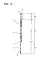
- FIG. 10 shows a leg sweep member 10 according to a fifth embodiment of the present invention.
- the thickness of the base plate 12 is made different among the sections, that is, so that the thickness becomes smaller in the order of the front section 26, the center section 30, and the rear section 28. This also allows the rigidity of the base plate 12 to become lower in the order of the front section 26, the center section 30, and the rear section 28.
- center section 30 of the base plate 12 has a uniform rigidity in the above embodiments, a plurality of areas having mutually different rigidities may be provided in the center section 30 so as to extend over the full dimension in the breadth direction, to adjoin in the depth direction, and to be arranged in decreasing order of the rigidities from a front side of the center section.
- FIG. 11 shows a leg sweep member 10 according to a sixth embodiment of the present invention.
- the center section 30 is further divided into two areas, that is, a front center area 84 and a rear center area 86.
- a plurality of first ribs 16 and a third rib 18, and a plurality of first auxiliary ribs 32 and a second auxiliary rib 34 respectively protrude on the upper surface and the lower surface of the front center area 84 so that the front center area 84 is less rigid than the front section 26 and more rigid than the rear section 28.
- the rear center area 86 is made thick so that the center area 86 is less rigid than the front center area 84 and is more rigid than the rear section 28.
- the base plate 12 is bent and deformed not only at the boundary portion 72 and the front adjacent portion 74, but also at a boundary portion between the front and rear center areas 84, 86 of the center section 30, depending on the volume of the shock applied in a collision between the leg portion 66 of the pedestrian and the front of the automobile (for example, the front bumper 40). This advantageously suppresses an excessive increase in the impact load in the early stage of the input of the shock.
- the number of the portions may be three or more.
- portions having mutually different rigidities are thus provided in the center section 30, for example, various types of ribs may be provided in the sections in different numbers or with different thicknesses, reinforcing members having different thicknesses may be fixed to the portions, or the portions may have different thicknesses. These structures may be appropriately adopted in combination.
- the present invention is advantageously applied not only to the pedestrian protection apparatus installed inside the bumper fixed at the front of the automobile, but also to a pedestrian protection apparatus installed at the front of the automobile independently of the bumper, and pedestrian protection apparatuses that are installed in various manners at the fronts of vehicles other than the automobile.
- a leg sweep member serving as a first invention example having a configuration according to the present invention was formed and prepared by ejection molding using polypropylene.
- the thickness and rigidity of a base plate become smaller in the order of a front section, a center section, and a rear section thereof, as shown in FIG. 10.
- the total dimension of the base plate in the depth direction is 200 mm, and the dimensions of the front section, the center section, and the rear section of the base plate are 50 mm, 100 mm, and 50 mm, respectively.
- the thicknesses of the front section, the center section, and the rear section are 3.0 mm, 2.5 mm, and 2.0 mm, respectively.
- a leg sweep member serving as a first comparative example was formed and prepared by ejection molding using polypropylene.
- the thicknesses of a front section, a center section, and a rear section of a base plate are 2.0 mm, 2.5 mm, and 3.0 mm, respectively. That is, the thickness of the base plate becomes larger in the order of the front section, the center section, and the rear section thereof so that the rigidity of the base plate becomes higher in the order of the front section, the center section, and the rear section thereof.
- a leg sweep member serving as a second comparative example was also formed and prepared by ejection molding using polypropylene.
- the thicknesses of a center section, a rear section, and a front section of a base plate are 3.0 mm, 2.5 mm, and 1.5 mm, respectively, so that the rigidity of the base plate becomes lower in the order of the center section, the rear section, and the front section thereof.
- a leg sweep member serving as a third comparative example was formed and prepared by ejection molding using polypropylene.
- a base plate has a uniform thickness of 2.5 mm, and has a uniform rigidity.
- the prepared leg sweep members having different structures that is, the first invention example and the first to third comparative examples were respectively mounted inside bumper covers of front bumpers fixed at the fronts of actual vehicles (automobiles), thereby obtaining four types of test vehicles.
- a pedestrian collision test was conducted on each of the test vehicles on the assumption that the front bumper of the test vehicle collided with a pedestrian, and it was checked in a known manner how the impact load inputted to each of the leg sweep members changed with time.
- FIG. 12 shows the test results.
- the front of the front bumper of the test vehicle was caused to collide with a dummy having a weight of 14 kg at a speed of 40 km/h.
- the impact load rapidly increased in the early stage of the input of the shock by the collision with the pedestrian, and instantaneously reached a target load after the collision.
- the impact load slowly increased in the early stage of the shock input, and reached the target load a relatively long time after the collision, or did not reach the target load. This clearly shows that a reaction force to the impact load can be sufficiently and reliably ensured in the leg sweep member having the structure according to the present invention.
- a leg sweep member having a configuration according to the present invention shown in FIGS. 1 to 3 was formed and prepared as a second invention example by ejection molding using polypropylene.
- the rigidity of a base plate becomes lower in the order of a front section, a center section, and a rear section because of first to fifth ribs provided on the front section and the center section.
- the total dimension of the base plate in the depth direction is 190 mm, and the dimensions of the front section, the center section, and the rear section of the base are 30 mm, 110 mm, and 50 mm, respectively.
- the each of the first to fifth ribs provided on the front section and the center section is 3 mm in thickness, and are 25 mm in height.
- a leg sweep member having a configuration according to the present invention was formed and prepared as a third invention example.
- the third invention example has the same basic structure as that of the above-described second invention example.
- the dimensions of a front section, a center section, and a rear section of a base plate in the depth direction are 30 mm, 130 mm, and 30 mm, respectively.
- the dimension of the base plate in the depth direction and the dimension of the front section in the depth direction are equal to those in the second invention example, but the dimension of the center section is larger and the dimension of the rear section is smaller than in the second invention example.
- leg sweep members of the second and third invention examples thus prepared and having different configurations were installed at the fronts of actual vehicles (automobiles), thereby obtaining two-types of test vehicles.
- a pedestrian collision test similar to that for the first example was conducted on each of the test vehicles, and it was checked in a known manner how the impact load inputted to the leg sweep member in a collision with the pedestrian changed with time.
- FIG. 13 shows the test results.
- the maximum value of the impact load in the leg sweep member of the third invention example, in which the center section of the base plate is longer in the depth direction, is larger than that of the leg sweep member of the second invention example in which the dimension of the center section in the depth direction is shorter.
- the load characteristic of the leg sweep member can be easily tuned by changing the dimension in the depth direction of the center section whose rigidity is between the rigidities of the front section and the rear section, and thereby adjusting the distance between the boundary portion between the center section and the rear section, and the front adjacent portion on the front side of and adjacent to the portion of the rear section fixed to the vehicle.
- leg sweep member of the second invention example in the above-described second example was prepared.
- a fourth invention example having a configuration according to the present invention shown in FIG. 8, and having a basic structure similar to that of the second invention example was prepared.
- an iron reinforcing plate having a predetermined flexural rigidity is fixed on a lower surface of a base plate so as to extend over a boundary portion and a front adjacent portion.
- the reinforcing plate has a thickness of 1.0 mm, and a dimension of 80 mm in the depth direction.
- the two-types of leg sweep members of the second and fourth invention examples were installed at the fronts of actual vehicles (automobiles) to obtain two-types of test vehicles. Subsequently, a pedestrian collision test similar to that for the first example was conducted on each of the test vehicles, and it was checked in a known manner how the impact load inputted to the leg sweep member in a collision with a pedestrian changed with time.
- FIG. 14 shows the test results.
- the maximum value of the impact load in the leg sweep member of the fourth invention example, in which the reinforcing plate is fixed on the lower surface of the base so as to extend over the boundary portion and the front adjacent portion is larger than that in the leg sweep member of the second invention example in which the reinforcing plate is not provided.
- the load characteristic of the leg sweep member can also be easily tuned by fixing the reinforcing plate on the lower surface of the base so as to extend over the boundary portion and the front adjacent portion.
- leg sweep member of the second invention example in the above-described second example was prepared.
- a leg sweep member having a basic structure similar to that of the second invention example was prepared as a fifth invention example.
- a reinforcing rib protrudes integrally from a lower surface of the base plate so as to extend over a boundary portion and a front adjacent portion.
- the dimension of the reinforcing rib in the depth direction is 80 mm, and the thickness thereof is 1.0 mm.
- the two-types of leg sweep members of the second and fifth invention examples were installed at the fronts of actual vehicles (automobiles) to obtain two-types of test vehicles. Subsequently, a pedestrian collision test similar to that in the first example was conducted on each of the test vehicles, and it was checked in a known manner how the impact load inputted to the leg sweep member in a collision with a pedestrian changed with time.
- FIG. 15 shows the test results.
- the maximum value of the impact load in the leg sweep member of the fifth invention example, in which the reinforcing rib is provided integrally with the lower surface of the base plate so as to extend over the boundary portion and the front adjacent portion, is larger than that in the leg sweep member of the second invention example in which the reinforcing rib is not provided.
- the load characteristic of the leg sweep member can also be easily tuned by forming the reinforcing rib integrally with the lower surface of the base so as to extend over the boundary portion and the front adjacent portion.
Applications Claiming Priority (1)
| Application Number | Priority Date | Filing Date | Title |
|---|---|---|---|
| JP2005304726A JP4171739B2 (ja) | 2005-10-19 | 2005-10-19 | 車両用歩行者保護装置並びにかかる装置における荷重特性のチューニング方法 |
Publications (3)
| Publication Number | Publication Date |
|---|---|
| EP1777125A2 true EP1777125A2 (de) | 2007-04-25 |
| EP1777125A3 EP1777125A3 (de) | 2007-07-04 |
| EP1777125B1 EP1777125B1 (de) | 2008-07-16 |
Family
ID=37660520
Family Applications (1)
| Application Number | Title | Priority Date | Filing Date |
|---|---|---|---|
| EP06254508A Not-in-force EP1777125B1 (de) | 2005-10-19 | 2006-08-30 | Fussgängerschutzvorrichtung und Verfahren zur Einstellung von Lastcharakteristiken der Vorrichtung |
Country Status (6)
| Country | Link |
|---|---|
| US (1) | US7597383B2 (de) |
| EP (1) | EP1777125B1 (de) |
| JP (1) | JP4171739B2 (de) |
| CN (1) | CN100410111C (de) |
| AT (1) | ATE401221T1 (de) |
| DE (1) | DE602006001820D1 (de) |
Cited By (2)
| Publication number | Priority date | Publication date | Assignee | Title |
|---|---|---|---|---|
| CN103381788A (zh) * | 2013-07-09 | 2013-11-06 | 奇瑞汽车股份有限公司 | 一种车辆行人上腿部保护装置及其装配方法 |
| DE202016107500U1 (de) * | 2016-12-30 | 2018-04-05 | Rehau Ag + Co | Fußgängerschutzvorrichtung für einen unteren Stoßbereich einer Kraftfahrzeug-Frontstoßfängerverkleidung |
Families Citing this family (34)
| Publication number | Priority date | Publication date | Assignee | Title |
|---|---|---|---|---|
| JP4171739B2 (ja) * | 2005-10-19 | 2008-10-29 | 小島プレス工業株式会社 | 車両用歩行者保護装置並びにかかる装置における荷重特性のチューニング方法 |
| US20070138815A1 (en) * | 2005-12-21 | 2007-06-21 | Kojima Press Industry Co., Ltd. | Pedestrian protection apparatus for vehicle |
| JP4908239B2 (ja) * | 2007-01-12 | 2012-04-04 | 小島プレス工業株式会社 | 車両用歩行者保護装置 |
| DE102007019481B4 (de) * | 2007-04-25 | 2017-10-19 | Volkswagen Ag | Frontendmodul für ein Fahrzeug, insbesondere für ein Kraftfahrzeug |
| US8042847B2 (en) * | 2007-12-19 | 2011-10-25 | Sabic Innovative Plastics Ip B.V. | Tray energy absorber and bumper system |
| US7988225B2 (en) * | 2008-03-31 | 2011-08-02 | Honda Motor Co., Ltd. | Vehicle front fascia support member |
| JP5112160B2 (ja) * | 2008-04-25 | 2013-01-09 | 小島プレス工業株式会社 | 車両用歩行者保護装置 |
| US7959197B2 (en) * | 2008-10-30 | 2011-06-14 | Shape Corp. | Bumper beam with multi-concavity-defining cross section |
| JP5324264B2 (ja) * | 2009-03-11 | 2013-10-23 | 株式会社オーテックジャパン | バンパー構造 |
| FR2943595B1 (fr) * | 2009-03-26 | 2011-06-03 | Faurecia Bloc Avant | Ensemble avant de vehicule automobile comprenant un bouclier pare-chocs avant |
| KR101090829B1 (ko) * | 2009-11-27 | 2011-12-08 | 기아자동차주식회사 | 차량용 스티프너 |
| JP5508211B2 (ja) * | 2010-09-30 | 2014-05-28 | 富士重工業株式会社 | 車両用歩行者保護装置 |
| US8322780B2 (en) | 2010-12-20 | 2012-12-04 | Sabic Innovative Plastics Ip B.V. | Reinforced body in white and method of making and using the same |
| US8449021B2 (en) | 2010-12-17 | 2013-05-28 | Sabic Innovative Plastics Ip B.V. | Vehicle lower-leg protection device and method of making and using the same |
| KR101443198B1 (ko) * | 2010-12-21 | 2014-09-22 | 도요타 지도샤(주) | 범퍼 모듈 |
| JP5801122B2 (ja) * | 2011-07-11 | 2015-10-28 | 小島プレス工業株式会社 | 車両用歩行者保護装置 |
| KR101364406B1 (ko) * | 2011-12-06 | 2014-02-18 | 기아자동차주식회사 | 충격 흡수 및 충격 차단 성능이 구비된 로워 스티프너 일체형 언더 커버 |
| JP5527828B2 (ja) * | 2012-07-27 | 2014-06-25 | 富士重工業株式会社 | 車両前部構造 |
| US9067550B2 (en) | 2013-01-18 | 2015-06-30 | Sabic Global Technologies B.V. | Polymer, energy absorber rail extension, methods of making and vehicles using the same |
| US8864216B2 (en) | 2013-01-18 | 2014-10-21 | Sabic Global Technologies B.V. | Reinforced body in white and method of making and using the same |
| DE102013002307A1 (de) * | 2013-02-06 | 2014-08-07 | GM Global Technology Operations LLC (n. d. Ges. d. Staates Delaware) | Frontpartie für ein Kraftfahrzeug |
| DE102013019124A1 (de) * | 2013-11-15 | 2015-05-21 | GM Global Technology Operations LLC (n. d. Ges. d. Staates Delaware) | Stoßfängerabstützung für ein Fahrzeug |
| WO2015143579A1 (en) * | 2014-03-28 | 2015-10-01 | Borouge Sales & Marketing (Shanghai) Co., Ltd. | Lower bumper stiffener and automotive vehicle thereof |
| US11603142B2 (en) | 2014-06-16 | 2023-03-14 | Sabic Global Technologies B.V. | Structural body of a vehicle having an energy absorbing device and a method of forming the energy absorbing device |
| US9327663B2 (en) | 2014-08-13 | 2016-05-03 | Ford Global Technologies, Llc | Adaptive energy absorber for a vehicle |
| US9067552B1 (en) | 2014-08-13 | 2015-06-30 | Ford Global Technologies, Llc | Adaptive energy absorber for a vehicle |
| US9327662B1 (en) | 2014-11-24 | 2016-05-03 | Toyota Motor Engineering & Manufacturing North America, Inc. | Bumper assemblies including lower reinforcement members |
| US10144386B2 (en) * | 2015-02-13 | 2018-12-04 | Ford Global Technologies, Llc | Belly pan and energy absorption system for a motor vehicle |
| US9580030B2 (en) | 2015-04-08 | 2017-02-28 | Toyota Motor Engineering & Manufacturing North America, Inc. | Bumper assemblies including lower reinforcement members |
| JP6579322B2 (ja) | 2015-12-25 | 2019-09-25 | スズキ株式会社 | 吸気シュラウド構造 |
| USD820749S1 (en) | 2015-12-29 | 2018-06-19 | Sabic Global Technologies B.V. | Roof component for a motor vehicle |
| EP3473497B1 (de) * | 2017-10-17 | 2021-11-03 | SABIC Global Technologies B.V. | Frontendmodul für ein elektrofahrzeug |
| CN108995619A (zh) * | 2017-11-09 | 2018-12-14 | 钱保中 | 不伤行人生命的安全装置 |
| CN112428951B (zh) * | 2020-12-07 | 2022-06-24 | 安徽江淮汽车集团股份有限公司 | 行人保护装置、车辆及其行人保护方法、装置及存储介质 |
Citations (3)
| Publication number | Priority date | Publication date | Assignee | Title |
|---|---|---|---|---|
| JP2001277963A (ja) | 2000-03-30 | 2001-10-10 | Fuji Heavy Ind Ltd | 自動車用バンパ構造 |
| JP2004025976A (ja) | 2002-06-25 | 2004-01-29 | Mazda Motor Corp | 車両用歩行者保護装置 |
| JP2004203183A (ja) | 2002-12-25 | 2004-07-22 | Toyota Motor Corp | 車両の前部車体構造 |
Family Cites Families (18)
| Publication number | Priority date | Publication date | Assignee | Title |
|---|---|---|---|---|
| US6634702B1 (en) | 1999-06-23 | 2003-10-21 | Dynamit Nobel Kunstsoff Gmbh | Front-end module for a motor vehicle |
| EP1065108B1 (de) * | 1999-06-28 | 2004-04-21 | Mazda Motor Corporation | Kraftfahrzeug- Vorderwagenaufbau |
| JP2002264741A (ja) * | 2001-03-08 | 2002-09-18 | Fuji Heavy Ind Ltd | バンパー構造 |
| JP2002274298A (ja) | 2001-03-15 | 2002-09-25 | Fuji Heavy Ind Ltd | 車両用バンパ構造 |
| EP1300293B1 (de) | 2001-09-28 | 2004-12-01 | Ford Global Technologies, LLC | Kraftfahrzeug nit Stossstangenanordnung zum Fussgängerschutz |
| US6685243B1 (en) * | 2002-07-30 | 2004-02-03 | Shape Corporation | Bumper for reducing pedestrian injury |
| US6886872B2 (en) * | 2002-12-25 | 2005-05-03 | Mazda Motor Corporation | Automobile bumper structure |
| JP3956846B2 (ja) * | 2002-12-25 | 2007-08-08 | マツダ株式会社 | 自動車の前部構造 |
| EP1692016A2 (de) * | 2003-12-09 | 2006-08-23 | Decoma (Germany) GmbH | Strukturbauteil einer kraftfahrzeug-stossfängeranordnung |
| DE102004007571B4 (de) | 2003-12-24 | 2017-12-21 | Volkswagen Ag | Vorderwagen für ein Fahrzeug, insbesondere für ein Kraftfahrzeug |
| DE102004035434A1 (de) * | 2004-07-21 | 2006-03-16 | Adam Opel Ag | Verstärkungselement für einen unteren Bereich eines Frontstoßfängers, sowie damit ausgerüsteter Frontstoßfänger für ein Kraftfahrzeug |
| JP2007055543A (ja) * | 2005-08-26 | 2007-03-08 | Kojima Press Co Ltd | 車両用歩行者保護装置 |
| JP4171739B2 (ja) * | 2005-10-19 | 2008-10-29 | 小島プレス工業株式会社 | 車両用歩行者保護装置並びにかかる装置における荷重特性のチューニング方法 |
| US20070138815A1 (en) * | 2005-12-21 | 2007-06-21 | Kojima Press Industry Co., Ltd. | Pedestrian protection apparatus for vehicle |
| US7517006B2 (en) * | 2006-01-31 | 2009-04-14 | Mazda Motor Corporation | Front structure of automotive vehicle |
| JP4317203B2 (ja) * | 2006-06-13 | 2009-08-19 | 小島プレス工業株式会社 | 車両用歩行者保護装置 |
| US7441828B2 (en) * | 2006-06-14 | 2008-10-28 | Kojima Press Industry Co., Ltd. | Pedestrian protection apparatus for vehicle |
| JP4908239B2 (ja) * | 2007-01-12 | 2012-04-04 | 小島プレス工業株式会社 | 車両用歩行者保護装置 |
-
2005
- 2005-10-19 JP JP2005304726A patent/JP4171739B2/ja active Active
-
2006
- 2006-08-16 US US11/504,893 patent/US7597383B2/en active Active
- 2006-08-30 DE DE602006001820T patent/DE602006001820D1/de active Active
- 2006-08-30 EP EP06254508A patent/EP1777125B1/de not_active Not-in-force
- 2006-08-30 AT AT06254508T patent/ATE401221T1/de not_active IP Right Cessation
- 2006-10-11 CN CNB2006101422985A patent/CN100410111C/zh active Active
Patent Citations (3)
| Publication number | Priority date | Publication date | Assignee | Title |
|---|---|---|---|---|
| JP2001277963A (ja) | 2000-03-30 | 2001-10-10 | Fuji Heavy Ind Ltd | 自動車用バンパ構造 |
| JP2004025976A (ja) | 2002-06-25 | 2004-01-29 | Mazda Motor Corp | 車両用歩行者保護装置 |
| JP2004203183A (ja) | 2002-12-25 | 2004-07-22 | Toyota Motor Corp | 車両の前部車体構造 |
Cited By (3)
| Publication number | Priority date | Publication date | Assignee | Title |
|---|---|---|---|---|
| CN103381788A (zh) * | 2013-07-09 | 2013-11-06 | 奇瑞汽车股份有限公司 | 一种车辆行人上腿部保护装置及其装配方法 |
| CN103381788B (zh) * | 2013-07-09 | 2016-06-01 | 奇瑞汽车股份有限公司 | 一种车辆行人上腿部保护装置及其装配方法 |
| DE202016107500U1 (de) * | 2016-12-30 | 2018-04-05 | Rehau Ag + Co | Fußgängerschutzvorrichtung für einen unteren Stoßbereich einer Kraftfahrzeug-Frontstoßfängerverkleidung |
Also Published As
| Publication number | Publication date |
|---|---|
| JP4171739B2 (ja) | 2008-10-29 |
| CN100410111C (zh) | 2008-08-13 |
| EP1777125A3 (de) | 2007-07-04 |
| DE602006001820D1 (de) | 2008-08-28 |
| JP2007112256A (ja) | 2007-05-10 |
| CN1951736A (zh) | 2007-04-25 |
| ATE401221T1 (de) | 2008-08-15 |
| US20070085356A1 (en) | 2007-04-19 |
| EP1777125B1 (de) | 2008-07-16 |
| US7597383B2 (en) | 2009-10-06 |
Similar Documents
| Publication | Publication Date | Title |
|---|---|---|
| EP1777125B1 (de) | Fussgängerschutzvorrichtung und Verfahren zur Einstellung von Lastcharakteristiken der Vorrichtung | |
| EP1800960B1 (de) | Fußgängerschutzvorrichtung für Kraftfahrzeuge | |
| EP1867526B1 (de) | Fußgängerschutzvorrichtung für Kraftfahrzeuge | |
| EP2189335B1 (de) | Fußgängerschutzvorrichtung für Kraftfahrzeuge | |
| KR101855303B1 (ko) | 에너지 흡수 조립체 | |
| EP1826069B1 (de) | Stossabsorbierende Struktur für Fahrzeug und deren Befestigungssystem | |
| EP1726490B1 (de) | Vorderwagenaufbau eines Kraftfahrzeuges | |
| EP2112027B1 (de) | Fußgängerschutzvorrichtung für Kraftfahrzeuge | |
| JP4890113B2 (ja) | 車両用歩行者保護装置 | |
| JP4732164B2 (ja) | 車両用歩行者保護装置 | |
| KR100805511B1 (ko) | 범퍼 조립체 및 에너지 흡수체 | |
| JP4890114B2 (ja) | 車両用歩行者保護装置 | |
| JP2007168594A (ja) | 車両用歩行者保護装置 | |
| JP5004124B2 (ja) | 車両用歩行者保護装置 | |
| JP6444824B2 (ja) | バンパアブソーバ | |
| KR20060020170A (ko) | 보행자 다리의 상해정도 저감을 위한 차량 전면범퍼구조 | |
| KR20060020169A (ko) | 보행자 다리의 상해정도 저감을 위한 차량 전면범퍼구조 |
Legal Events
| Date | Code | Title | Description |
|---|---|---|---|
| PUAI | Public reference made under article 153(3) epc to a published international application that has entered the european phase |
Free format text: ORIGINAL CODE: 0009012 |
|
| AK | Designated contracting states |
Kind code of ref document: A2 Designated state(s): AT BE BG CH CY CZ DE DK EE ES FI FR GB GR HU IE IS IT LI LT LU LV MC NL PL PT RO SE SI SK TR |
|
| AX | Request for extension of the european patent |
Extension state: AL BA HR MK YU |
|
| PUAL | Search report despatched |
Free format text: ORIGINAL CODE: 0009013 |
|
| AK | Designated contracting states |
Kind code of ref document: A3 Designated state(s): AT BE BG CH CY CZ DE DK EE ES FI FR GB GR HU IE IS IT LI LT LU LV MC NL PL PT RO SE SI SK TR |
|
| AX | Request for extension of the european patent |
Extension state: AL BA HR MK YU |
|
| 17P | Request for examination filed |
Effective date: 20070926 |
|
| GRAC | Information related to communication of intention to grant a patent modified |
Free format text: ORIGINAL CODE: EPIDOSCIGR1 |
|
| GRAP | Despatch of communication of intention to grant a patent |
Free format text: ORIGINAL CODE: EPIDOSNIGR1 |
|
| AKX | Designation fees paid |
Designated state(s): AT BE BG CH CY CZ DE DK EE ES FI FR GB GR HU IE IS IT LI LT LU LV MC NL PL PT RO SE SI SK TR |
|
| GRAS | Grant fee paid |
Free format text: ORIGINAL CODE: EPIDOSNIGR3 |
|
| GRAA | (expected) grant |
Free format text: ORIGINAL CODE: 0009210 |
|
| AK | Designated contracting states |
Kind code of ref document: B1 Designated state(s): AT BE BG CH CY CZ DE DK EE ES FI FR GB GR HU IE IS IT LI LT LU LV MC NL PL PT RO SE SI SK TR |
|
| REG | Reference to a national code |
Ref country code: GB Ref legal event code: FG4D |
|
| RIN1 | Information on inventor provided before grant (corrected) |
Inventor name: FUKUKAWA, MASANOBUKOJIMA PRESS INDUSTRY CO., LTD. Inventor name: HASEGAWA, KUNIAKIKOJIMA PRESS INDUSTRY CO., LTD. Inventor name: KUROKAWA, HIROKI C/O TOYOTA JIDOSHA KABUSHIKI K. Inventor name: OGURA, YOSHIHIRO KOJIMA PRESS INDUSTRY CO., LTD. Inventor name: ITOU, KAORU KOJIMA PRESS INDUSTRY CO., LTD. |
|
| REG | Reference to a national code |
Ref country code: CH Ref legal event code: EP |
|
| REF | Corresponds to: |
Ref document number: 602006001820 Country of ref document: DE Date of ref document: 20080828 Kind code of ref document: P |
|
| REG | Reference to a national code |
Ref country code: IE Ref legal event code: FG4D |
|
| NLV1 | Nl: lapsed or annulled due to failure to fulfill the requirements of art. 29p and 29m of the patents act | ||
| PG25 | Lapsed in a contracting state [announced via postgrant information from national office to epo] |
Ref country code: NL Free format text: LAPSE BECAUSE OF FAILURE TO SUBMIT A TRANSLATION OF THE DESCRIPTION OR TO PAY THE FEE WITHIN THE PRESCRIBED TIME-LIMIT Effective date: 20080716 Ref country code: IS Free format text: LAPSE BECAUSE OF FAILURE TO SUBMIT A TRANSLATION OF THE DESCRIPTION OR TO PAY THE FEE WITHIN THE PRESCRIBED TIME-LIMIT Effective date: 20081116 Ref country code: LT Free format text: LAPSE BECAUSE OF FAILURE TO SUBMIT A TRANSLATION OF THE DESCRIPTION OR TO PAY THE FEE WITHIN THE PRESCRIBED TIME-LIMIT Effective date: 20080716 |
|
| PG25 | Lapsed in a contracting state [announced via postgrant information from national office to epo] |
Ref country code: ES Free format text: LAPSE BECAUSE OF FAILURE TO SUBMIT A TRANSLATION OF THE DESCRIPTION OR TO PAY THE FEE WITHIN THE PRESCRIBED TIME-LIMIT Effective date: 20081027 Ref country code: PT Free format text: LAPSE BECAUSE OF FAILURE TO SUBMIT A TRANSLATION OF THE DESCRIPTION OR TO PAY THE FEE WITHIN THE PRESCRIBED TIME-LIMIT Effective date: 20081216 Ref country code: LV Free format text: LAPSE BECAUSE OF FAILURE TO SUBMIT A TRANSLATION OF THE DESCRIPTION OR TO PAY THE FEE WITHIN THE PRESCRIBED TIME-LIMIT Effective date: 20080716 Ref country code: FI Free format text: LAPSE BECAUSE OF FAILURE TO SUBMIT A TRANSLATION OF THE DESCRIPTION OR TO PAY THE FEE WITHIN THE PRESCRIBED TIME-LIMIT Effective date: 20080716 Ref country code: AT Free format text: LAPSE BECAUSE OF FAILURE TO SUBMIT A TRANSLATION OF THE DESCRIPTION OR TO PAY THE FEE WITHIN THE PRESCRIBED TIME-LIMIT Effective date: 20080716 Ref country code: SI Free format text: LAPSE BECAUSE OF FAILURE TO SUBMIT A TRANSLATION OF THE DESCRIPTION OR TO PAY THE FEE WITHIN THE PRESCRIBED TIME-LIMIT Effective date: 20080716 Ref country code: BG Free format text: LAPSE BECAUSE OF FAILURE TO SUBMIT A TRANSLATION OF THE DESCRIPTION OR TO PAY THE FEE WITHIN THE PRESCRIBED TIME-LIMIT Effective date: 20081016 |
|
| PG25 | Lapsed in a contracting state [announced via postgrant information from national office to epo] |
Ref country code: BE Free format text: LAPSE BECAUSE OF FAILURE TO SUBMIT A TRANSLATION OF THE DESCRIPTION OR TO PAY THE FEE WITHIN THE PRESCRIBED TIME-LIMIT Effective date: 20080716 Ref country code: MC Free format text: LAPSE BECAUSE OF NON-PAYMENT OF DUE FEES Effective date: 20080831 |
|
| PG25 | Lapsed in a contracting state [announced via postgrant information from national office to epo] |
Ref country code: EE Free format text: LAPSE BECAUSE OF FAILURE TO SUBMIT A TRANSLATION OF THE DESCRIPTION OR TO PAY THE FEE WITHIN THE PRESCRIBED TIME-LIMIT Effective date: 20080716 Ref country code: DK Free format text: LAPSE BECAUSE OF FAILURE TO SUBMIT A TRANSLATION OF THE DESCRIPTION OR TO PAY THE FEE WITHIN THE PRESCRIBED TIME-LIMIT Effective date: 20080716 |
|
| PLBE | No opposition filed within time limit |
Free format text: ORIGINAL CODE: 0009261 |
|
| STAA | Information on the status of an ep patent application or granted ep patent |
Free format text: STATUS: NO OPPOSITION FILED WITHIN TIME LIMIT |
|
| PG25 | Lapsed in a contracting state [announced via postgrant information from national office to epo] |
Ref country code: RO Free format text: LAPSE BECAUSE OF FAILURE TO SUBMIT A TRANSLATION OF THE DESCRIPTION OR TO PAY THE FEE WITHIN THE PRESCRIBED TIME-LIMIT Effective date: 20080716 Ref country code: CZ Free format text: LAPSE BECAUSE OF FAILURE TO SUBMIT A TRANSLATION OF THE DESCRIPTION OR TO PAY THE FEE WITHIN THE PRESCRIBED TIME-LIMIT Effective date: 20080716 Ref country code: SK Free format text: LAPSE BECAUSE OF FAILURE TO SUBMIT A TRANSLATION OF THE DESCRIPTION OR TO PAY THE FEE WITHIN THE PRESCRIBED TIME-LIMIT Effective date: 20080716 |
|
| 26N | No opposition filed |
Effective date: 20090417 |
|
| PG25 | Lapsed in a contracting state [announced via postgrant information from national office to epo] |
Ref country code: IE Free format text: LAPSE BECAUSE OF NON-PAYMENT OF DUE FEES Effective date: 20080830 |
|
| PG25 | Lapsed in a contracting state [announced via postgrant information from national office to epo] |
Ref country code: SE Free format text: LAPSE BECAUSE OF FAILURE TO SUBMIT A TRANSLATION OF THE DESCRIPTION OR TO PAY THE FEE WITHIN THE PRESCRIBED TIME-LIMIT Effective date: 20081016 |
|
| PG25 | Lapsed in a contracting state [announced via postgrant information from national office to epo] |
Ref country code: PL Free format text: LAPSE BECAUSE OF FAILURE TO SUBMIT A TRANSLATION OF THE DESCRIPTION OR TO PAY THE FEE WITHIN THE PRESCRIBED TIME-LIMIT Effective date: 20080716 |
|
| PG25 | Lapsed in a contracting state [announced via postgrant information from national office to epo] |
Ref country code: CY Free format text: LAPSE BECAUSE OF FAILURE TO SUBMIT A TRANSLATION OF THE DESCRIPTION OR TO PAY THE FEE WITHIN THE PRESCRIBED TIME-LIMIT Effective date: 20080716 Ref country code: LU Free format text: LAPSE BECAUSE OF NON-PAYMENT OF DUE FEES Effective date: 20080830 Ref country code: HU Free format text: LAPSE BECAUSE OF FAILURE TO SUBMIT A TRANSLATION OF THE DESCRIPTION OR TO PAY THE FEE WITHIN THE PRESCRIBED TIME-LIMIT Effective date: 20090117 |
|
| PG25 | Lapsed in a contracting state [announced via postgrant information from national office to epo] |
Ref country code: TR Free format text: LAPSE BECAUSE OF FAILURE TO SUBMIT A TRANSLATION OF THE DESCRIPTION OR TO PAY THE FEE WITHIN THE PRESCRIBED TIME-LIMIT Effective date: 20080716 |
|
| PG25 | Lapsed in a contracting state [announced via postgrant information from national office to epo] |
Ref country code: GR Free format text: LAPSE BECAUSE OF FAILURE TO SUBMIT A TRANSLATION OF THE DESCRIPTION OR TO PAY THE FEE WITHIN THE PRESCRIBED TIME-LIMIT Effective date: 20081017 |
|
| REG | Reference to a national code |
Ref country code: CH Ref legal event code: PL |
|
| PG25 | Lapsed in a contracting state [announced via postgrant information from national office to epo] |
Ref country code: LI Free format text: LAPSE BECAUSE OF NON-PAYMENT OF DUE FEES Effective date: 20100831 Ref country code: CH Free format text: LAPSE BECAUSE OF NON-PAYMENT OF DUE FEES Effective date: 20100831 |
|
| REG | Reference to a national code |
Ref country code: FR Ref legal event code: PLFP Year of fee payment: 11 |
|
| REG | Reference to a national code |
Ref country code: FR Ref legal event code: PLFP Year of fee payment: 12 |
|
| REG | Reference to a national code |
Ref country code: FR Ref legal event code: PLFP Year of fee payment: 13 |
|
| PGFP | Annual fee paid to national office [announced via postgrant information from national office to epo] |
Ref country code: IT Payment date: 20180830 Year of fee payment: 13 Ref country code: FR Payment date: 20180827 Year of fee payment: 13 Ref country code: DE Payment date: 20180823 Year of fee payment: 13 |
|
| PGFP | Annual fee paid to national office [announced via postgrant information from national office to epo] |
Ref country code: GB Payment date: 20180822 Year of fee payment: 13 |
|
| REG | Reference to a national code |
Ref country code: DE Ref legal event code: R119 Ref document number: 602006001820 Country of ref document: DE |
|
| GBPC | Gb: european patent ceased through non-payment of renewal fee |
Effective date: 20190830 |
|
| PG25 | Lapsed in a contracting state [announced via postgrant information from national office to epo] |
Ref country code: FR Free format text: LAPSE BECAUSE OF NON-PAYMENT OF DUE FEES Effective date: 20190831 Ref country code: DE Free format text: LAPSE BECAUSE OF NON-PAYMENT OF DUE FEES Effective date: 20200303 |
|
| PG25 | Lapsed in a contracting state [announced via postgrant information from national office to epo] |
Ref country code: GB Free format text: LAPSE BECAUSE OF NON-PAYMENT OF DUE FEES Effective date: 20190830 Ref country code: IT Free format text: LAPSE BECAUSE OF NON-PAYMENT OF DUE FEES Effective date: 20190830 |