EP1773539B1 - Verfahren und vorrichtung zur bearbeitung von oberflächen von optischen werkstücken - Google Patents
Verfahren und vorrichtung zur bearbeitung von oberflächen von optischen werkstücken Download PDFInfo
- Publication number
- EP1773539B1 EP1773539B1 EP05768577A EP05768577A EP1773539B1 EP 1773539 B1 EP1773539 B1 EP 1773539B1 EP 05768577 A EP05768577 A EP 05768577A EP 05768577 A EP05768577 A EP 05768577A EP 1773539 B1 EP1773539 B1 EP 1773539B1
- Authority
- EP
- European Patent Office
- Prior art keywords
- workpiece
- tool
- axis
- optical
- rotation
- Prior art date
- Legal status (The legal status is an assumption and is not a legal conclusion. Google has not performed a legal analysis and makes no representation as to the accuracy of the status listed.)
- Expired - Lifetime
Links
Images

Classifications
-
- B—PERFORMING OPERATIONS; TRANSPORTING
- B24—GRINDING; POLISHING
- B24B—MACHINES, DEVICES, OR PROCESSES FOR GRINDING OR POLISHING; DRESSING OR CONDITIONING OF ABRADING SURFACES; FEEDING OF GRINDING, POLISHING, OR LAPPING AGENTS
- B24B13/00—Machines or devices designed for grinding or polishing optical surfaces on lenses or surfaces of similar shape on other work; Accessories therefor
- B24B13/02—Machines or devices designed for grinding or polishing optical surfaces on lenses or surfaces of similar shape on other work; Accessories therefor by means of tools with abrading surfaces corresponding in shape with the lenses to be made
- B24B13/023—Machines or devices designed for grinding or polishing optical surfaces on lenses or surfaces of similar shape on other work; Accessories therefor by means of tools with abrading surfaces corresponding in shape with the lenses to be made for grinding several lenses simultaneously
-
- B—PERFORMING OPERATIONS; TRANSPORTING
- B24—GRINDING; POLISHING
- B24B—MACHINES, DEVICES, OR PROCESSES FOR GRINDING OR POLISHING; DRESSING OR CONDITIONING OF ABRADING SURFACES; FEEDING OF GRINDING, POLISHING, OR LAPPING AGENTS
- B24B13/00—Machines or devices designed for grinding or polishing optical surfaces on lenses or surfaces of similar shape on other work; Accessories therefor
-
- Y—GENERAL TAGGING OF NEW TECHNOLOGICAL DEVELOPMENTS; GENERAL TAGGING OF CROSS-SECTIONAL TECHNOLOGIES SPANNING OVER SEVERAL SECTIONS OF THE IPC; TECHNICAL SUBJECTS COVERED BY FORMER USPC CROSS-REFERENCE ART COLLECTIONS [XRACs] AND DIGESTS
- Y10—TECHNICAL SUBJECTS COVERED BY FORMER USPC
- Y10T—TECHNICAL SUBJECTS COVERED BY FORMER US CLASSIFICATION
- Y10T82/00—Turning
- Y10T82/10—Process of turning
-
- Y—GENERAL TAGGING OF NEW TECHNOLOGICAL DEVELOPMENTS; GENERAL TAGGING OF CROSS-SECTIONAL TECHNOLOGIES SPANNING OVER SEVERAL SECTIONS OF THE IPC; TECHNICAL SUBJECTS COVERED BY FORMER USPC CROSS-REFERENCE ART COLLECTIONS [XRACs] AND DIGESTS
- Y10—TECHNICAL SUBJECTS COVERED BY FORMER USPC
- Y10T—TECHNICAL SUBJECTS COVERED BY FORMER US CLASSIFICATION
- Y10T82/00—Turning
- Y10T82/25—Lathe
Definitions
- the invention relates to a method for processing O-surfaces of optical workpieces with non-rotationally symmetrical and / or asphotschen surfaces, such as lenses or spectacle lenses, with at least one tool, wherein at least one optical workpiece is held in a rotating about an axis of a workpiece spindle workpiece holder. Furthermore, the invention also relates to a processing device for carrying out such a method.
- the workpiece is clamped in a workpiece holder, which is located on a workpiece spindle.
- a workpiece axis of the workpiece coincides with a rotation axis of the workpiece spindle.
- the surface of the workpiece is given a precisely defined surface shape by pre-machining with a diamond-tipped grinding, milling or turning tool. With a finer tool, the surface is revised again. Subsequent polishing of the surface gives it the desired surface quality.
- This type of production of spectacle lenses is for example from the DE 196 16 526 A1 and from the DE 102 48 103 A1 known.
- optical workpieces such as optical lenses or spectacle lenses
- the workpiece axis of the workpiece and thus also of the tool holder do not coincide with the axis of rotation of the workpiece spindle.
- the axis of rotation of the workpiece spindle extends outside of the at least one workpiece, whereby a cutting speed of 0 is eliminated and in this way the center problem is completely eliminated.
- Another advantage is that multiple workpieces can be processed simultaneously on the workpiece spindle. A Such parallel machining of the workpieces leads to an increase in efficiency, lower costs and time savings.
- the axis of the tool holder can be identical to the workpiece axis, but this is basically not necessary.
- Claim 24 specifies a processing device according to the invention with which the method according to the invention can be carried out.
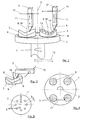
- FIG. 1 is a, only shown in broken lines processing device 1, in the present case, a lathe, with a workpiece spindle 1 ', which has a rotation axis 2 shown.
- a lathe on the workpiece spindle 1 'are in this embodiment, two workpieces 3, which are each held in a very schematically illustrated workpiece holder 4, stored.
- the workpieces 3 can be designed as optical workpieces, such as optical lenses or spectacle lenses. In this as well as in the following embodiments of blanks of the lenses is assumed as workpieces 3.
- the workpiece spindle 1 ' rotateates about its axis of rotation 2 according to arrow 7.
- a diamond tool is usually used as the tool 5.
- Polycrystalline diamond tools for preprocessing and monocrystalline diamond tools for fine machining are advantageously used for producing organic spectacle lenses.
- only one workpiece 3 can be mounted on the workpiece spindle 1 'for processing.
- FIG. 1 the axis of rotation 2 of the workpiece spindle 1 'extends through the special workpiece arrangement during this turning outside of the lenses to be produced.
- the workpiece axes 8 of the workpieces 3 corresponding to the axes of the workpiece holders 4 run parallel to the axis of rotation 2 of the workpiece spindle 1 ', but they do not coincide with the axis of rotation 2 of the workpiece spindle 1'.
- a slight deviation from the parallelism between the workpiece axis 8 and the axis of rotation may also be advantageous, as will be explained in greater detail below with reference to FIG. 3 with the axis 8.
- the workpiece axes 8 correspond to the axes 18 of the workpiece holders 4, although this is not necessarily the case.
- the workpieces 3 are mounted in one plane on the workpiece spindle 1 '.
- the axial tool delivery takes place via the highly dynamic tool delivery unit 9.
- This highly dynamic tool delivery unit 9 can be simultaneously controlled and / or regulated to the other machine axes and allows the production of non-rotationally symmetric components on lathes. Usually these are driven as piezoelectric or Lorentz driven drives; but any other way to realize the Zustellieri is conceivable.
- the angle and the position of the tool 5, in the case of the turning operation present here by means of a turning tool are recorded and the necessary delivery is calculated online.
- the highly dynamic drive varies the delivery of the tool 5 according to the desired contour.
- 5 rotationally symmetric as well as non-rotationally symmetric surfaces can be produced effectively and economically with the help of suitable tools. Since the machining is a continuous cutting movement, better surface qualities can be achieved than with a broken-cut milling process.
- a tool delivery unit with a stroke frequency of> 15,000 Hz, preferably> 20,000 Hz with a stroke of up to 35 mm is used.
- a surface roughness RMS of ⁇ 20 nm, even between 2-10 nm, can be achieved.
- the coupling of the rotation axis 2 with the feed movement of the tool 5 is necessary. This is about the Tool delivery unit 9 realized.
- the tool delivery unit 9 allows during a spindle rotation defined changes in the delivery function of the angular position of the workpiece spindle 1 '.
- very high acceleration values or stroke frequencies must be achieved with simultaneously high travel precision.
- a continuous radial feed of the tool 5 is in FIG. 1 represented by the arrows 10.
- the dynamic tool delivery takes place synchronously to the workpiece spindle 1 'by means of the tool delivery unit 9 and is represented by the arrow 11.
- An alternative realization of the radial feed can also be done by moving the workpiece spindle 1 'along the arrows 12.
- a split of the required radial and axial infeed to the tool 5 and the workpiece 3 can thus result in advantages with regard to machine accuracy, machine dynamics, vibration damping, etc.
- the axial feed can be done by the tool 5 and the radial feed through the workpiece spindle 1 '.
- the turning of the workpieces 3 by means of the tool 5 will only be described briefly here, since this is generally already known from the prior art.
- the tool 5 makes relatively short fast axial up and down movements and thereby brings the desired contour gradually into the workpieces 3 a.
- the tool 5 Per revolution of the workpiece spindle 1 'about its axis of rotation 2, the tool 5 performs parallel to the axis of rotation 2 more strokes by means of the tool delivery unit 9, whereby a delivery of the tool 5 at a very high frequency is guaranteed.
- a plurality of workpieces 3 can be machined on the workpiece spindle 1 'by means of the tool 5, whereby the regions of the surfaces of the workpieces 3 are provided with the contour predetermined by the processing apparatus 1.
- the machining of the surfaces of the workpieces 3 can also take place from the axis of rotation 2 in the direction of the edge of the workpiece spindle 1 '.
- trajectory trajectory segments with the lower requirements for the delivery movements, that is, surface curvatures with a larger radius, tangential to the cutting direction of the tool.
- Such advantageous trajectory segments are in FIG. 1 provided with the reference numeral 13 and shown for simplicity only in a workpiece 3 by lines.
- trajectory is meant the travel of the tool 5, which the tool 5 travels for processing during its multiple spiral 360 ° C revolution, comparable to a record.
- the feed direction 10 of the tool thus runs perpendicular to the circulation of the tool 5 or radially, for example from outside to inside.
- the above-described feed movements of the tool 5 are an optimization in terms of accuracy and time, since in this way the inevitable lifting movements are kept as low as possible.
- This delivery method can be applied to all forms of surfaces, such as free-form surfaces, symmetrical, asymmetric and aspherical surfaces of the workpieces 3.
- the workpiece to be machined can also be clamped in the tool holder 4 such that the workpiece axis 8 is tilted at a corresponding angle to the axis of rotation 2 of the workpiece spindle 1 ' like this from the FIG. 3 with the reference numeral "8 '" and the dashed representation can be removed.
- the axis 18 of the workpiece holder 4 itself can be tilted together with the workpiece axis 8 '.
- the inclination and thus the deviation from the parallelism can be up to 5-10 °, for example.
- FIG. 2 shows the machining of the workpieces 3 with tools 5 'and 5 ", which in this exemplary embodiment represent two different tools Since, in principle, the arrangement of the workpieces 3 on the workpiece spindle 1' according to the exemplary embodiment of FIGS FIG. 1 corresponds, the same reference numerals have been used for the same parts. As in FIG. 2 can be seen, the use of multiple tools 5 'and 5'' possible, so as to shorten the processing time of the workpieces 3 substantially.
- the radial feed of the tools 5 'and 5 also takes place in each case from the outer region of the workpiece spindle 1' towards its axis of rotation 2.
- the radial feed of the rotation axis 2 outwards, opposite to the direction of the arrow 10.
- the alternative realization of the radial feed, in which the workpiece spindle 1 'reciprocates according to the arrows 12, is also possible here, but then contrary to the illustration in FIG FIG. 2 the tools 5 'and 5 "are to be arranged sequentially in the feed direction on one side of the workpiece spindle 1'.
- FIG. 3 the delivery of the tools 5, 5 'and 5 ", as in the FIGS. 1 and 2 shown, not linear, but via a rotational movement or pivoting movements are realized, as shown in FIG. 3 is shown by way of example.
- the tool 5 and thus the tool cutting edge 6 oscillates about an axis of rotation 15, wherein only a slight movement of the tool 5 according to the arrow 16 is up and down.
- Such an embodiment of the tool 5 or such a processing of the workpieces 3 by the tool 5 from FIG. 3 is to the effect of advantage, since the rotation axis 15 is easier and more precise manufacturable than an axial feed or a linear guide.
- FIG. 4 is the workpiece spindle 1 'shown with the workpieces 3 thereon in plan view.
- the workpieces 3 can be provided with the same optical surfaces, but also different optical surfaces, such as spherical surfaces, toric surfaces, symmetrical aspherical surfaces or asymmetric aspherical surfaces simultaneously with the tool 5 and with the tools 5 'and 5 "in In this way, simultaneously rotationally symmetric and non-rotationally symmetrical workpieces 3 can be produced on the workpiece spindle 1 'Also, workpieces of different materials can be processed simultaneously, provided that the same processing parameters as cutting speed, feed, etc. , So similarities in Spanpli exist.
- a gap 17 or the travel path of the tool 5 or 5 'and 5 "between the individual workpieces 3 is to be interpolated with suitable path parameters.
- the corresponding surface portions of the intermediate spaces 17 between the respective workpieces 3 are to be interpolated so that the individual workpieces 3 which are arranged on the workpiece spindle 1 'are part of an imaginary total area and this total imaginary area with the tool 5 or with the tools 5 'and 5''is traversed.
- the tool 5, 5 'or 5 only in engagement when this imaginary,prooffahrende surface cuts the workpieces 3.
- the clearances or the distances X between the workpieces 3 to be machined should not be greater than 30 mm, preferably not greater than 10 mm (see FIG. 2 ).
- FIG. 5 shows a plan view of the workpiece spindle with multiple workpieces 3.
- the workpieces in any form - depending on the requirements - be arranged on the workpiece spindle 1 '.
- an arrangement in a ring shape is possible, as well as additionally or alternatively a plurality of workpieces 3, which can be arranged radially from the inside to the outside in succession.
- An asymmetric arrangement is possible.
- the processing device can be used not only for machining the workpieces 3, but also for grinding or polishing, which can optionally be done sequentially or simultaneously during the machining of other workpieces 3.
- this can also be arranged horizontally, whereby the axes 2, 8 and 18 are also arranged horizontally instead of vertically are.
Landscapes
- Engineering & Computer Science (AREA)
- Mechanical Engineering (AREA)
- Turning (AREA)
- Grinding And Polishing Of Tertiary Curved Surfaces And Surfaces With Complex Shapes (AREA)
- Finish Polishing, Edge Sharpening, And Grinding By Specific Grinding Devices (AREA)
- Surface Treatment Of Glass (AREA)
Applications Claiming Priority (2)
| Application Number | Priority Date | Filing Date | Title |
|---|---|---|---|
| DE102004037454A DE102004037454A1 (de) | 2004-08-02 | 2004-08-02 | Verfahren zur Bearbeitung von Oberflächen von Werkstücken |
| PCT/EP2005/008329 WO2006015761A1 (de) | 2004-08-02 | 2005-08-02 | Verfahren und vorrichtung zur bearbeitung von oberflächen von optischen werkstücken |
Publications (2)
| Publication Number | Publication Date |
|---|---|
| EP1773539A1 EP1773539A1 (de) | 2007-04-18 |
| EP1773539B1 true EP1773539B1 (de) | 2008-04-02 |
Family
ID=35355130
Family Applications (1)
| Application Number | Title | Priority Date | Filing Date |
|---|---|---|---|
| EP05768577A Expired - Lifetime EP1773539B1 (de) | 2004-08-02 | 2005-08-02 | Verfahren und vorrichtung zur bearbeitung von oberflächen von optischen werkstücken |
Country Status (7)
| Country | Link |
|---|---|
| US (1) | US7765903B2 (enExample) |
| EP (1) | EP1773539B1 (enExample) |
| JP (1) | JP2008508109A (enExample) |
| CN (1) | CN101031388B (enExample) |
| AT (1) | ATE390987T1 (enExample) |
| DE (2) | DE102004037454A1 (enExample) |
| WO (1) | WO2006015761A1 (enExample) |
Families Citing this family (19)
| Publication number | Priority date | Publication date | Assignee | Title |
|---|---|---|---|---|
| US7508116B2 (en) * | 2005-09-07 | 2009-03-24 | Panasonic Corporation | Method and apparatus for vibration machining with two independent axes |
| DE102006026524A1 (de) * | 2006-06-06 | 2007-12-13 | Satisloh Ag | Maschine zur Bearbeitung von optischen Werkstücken, insbesondere von Kunststoff-Brillengläsern |
| WO2008120691A1 (ja) * | 2007-03-29 | 2008-10-09 | Hoya Corporation | レンズ加工方法およびレンズ加工装置 |
| JP5325497B2 (ja) * | 2008-08-14 | 2013-10-23 | Hoya株式会社 | レンズ加工方法およびレンズ加工装置 |
| EP2500134A1 (fr) * | 2011-03-16 | 2012-09-19 | Comadur S.A. | Pièce d'habillage pour une pièce d'horlogerie et son système de fabrication |
| DE102013000494A1 (de) * | 2013-01-15 | 2014-07-17 | Friedrich Polzer | Vorrichtung zur Bearbeitung von Linsenrohlingen |
| DE102013005714B4 (de) * | 2013-04-02 | 2017-03-23 | Rodenstock Gmbh | Erzeugung mikrostrukturierter Brillengläser in der Rezeptglas-Fertigung |
| CN103753370A (zh) * | 2014-01-06 | 2014-04-30 | 南阳示佳光电有限公司 | 一盘多件式抛光模装置 |
| CN104942677B (zh) * | 2015-05-20 | 2017-08-25 | 秦晗 | 全自动玻璃镜片、玻璃保护屏专用研磨机 |
| JP6943862B2 (ja) | 2015-09-29 | 2021-10-06 | アーベーベー・シュバイツ・アーゲーABB Schweiz AG | 機械加工のための方法及びシステム |
| DE102015120853B3 (de) * | 2015-12-01 | 2017-04-27 | Friedrich-Schiller-Universität Jena | Verfahren und Vorrichtung zur Herstellung eines optischen Bauteils mit mindestens drei monolithisch angeordneten optischen Funktionsflächen und optisches Bauteil |
| DE102016000841A1 (de) * | 2016-01-27 | 2017-07-27 | J.G. WEISSER SöHNE GMBH & CO. KG | Verfahren zur spanenden Bearbeitung eines Werkstücks, Werkzeugkopf für eine Drehmaschine sowie Drehmaschine |
| CN105834851B (zh) * | 2016-04-20 | 2018-05-01 | 广州蓝海自动化设备科技有限公司 | 一种玻璃面板自动扫光设备 |
| US10040162B2 (en) * | 2016-09-09 | 2018-08-07 | Thielenhaus Technologies Gmbh | Device for producing a curved surface |
| EP3479936A1 (de) | 2017-11-03 | 2019-05-08 | Siemens Aktiengesellschaft | Drehen von werkstücken auf einer werkzeugmaschine |
| TWI802839B (zh) * | 2021-01-22 | 2023-05-21 | 揚明光學股份有限公司 | 具有自由曲面的模仁及其製造方法、以及使用該模仁來製作鏡片的方法與鏡片 |
| EP4063046A1 (de) | 2021-03-23 | 2022-09-28 | Licardor GmbH | Verfahren und vorrichtung zur drehbearbeitung von werkstücken |
| CN113927407B (zh) * | 2021-09-22 | 2024-01-05 | 南京茂莱光学科技股份有限公司 | 适用于多片透镜毛坯加工成精磨成品的加工装置及加工方法 |
| DE102021133373A1 (de) | 2021-12-15 | 2023-06-15 | tooz technologies GmbH | BEARBEITEN VON AUßERAXIAL ANGEORDNETEN OPTISCHEN WERKSTÜCKEN |
Family Cites Families (16)
| Publication number | Priority date | Publication date | Assignee | Title |
|---|---|---|---|---|
| DE1072502B (de) * | 1959-12-31 | Wuppertall-Barmen Arthur Schulze | Maschine zum Schleifen und Polieren optischer Flächen | |
| GB563067A (en) | 1943-04-14 | 1944-07-27 | Percy Lever | Improvements in or relating to grinding and polishing machines |
| US4680998A (en) * | 1984-08-28 | 1987-07-21 | Bausch & Lomb Incorporated | Toric lenses, method and apparatus for making same |
| US4862646A (en) | 1986-01-28 | 1989-09-05 | Laser Magnetic Storage International Company | Apparatus and method for production of single element toric lenses of very small proportions |
| JP2602293B2 (ja) * | 1988-08-12 | 1997-04-23 | 株式会社日立製作所 | 非球面形状物体の加工方法及び加工装置 |
| JPH0425366A (ja) * | 1990-05-21 | 1992-01-29 | Matsushita Electric Ind Co Ltd | 曲面加工装置 |
| EP0854769B1 (de) * | 1995-10-14 | 2002-02-27 | Carl Zeiss | Verfahren zum herstellen von optischen oberflächen sowie bearbeitungsmaschine zur durchführung des verfahrens |
| DE19616526A1 (de) | 1996-04-25 | 1997-11-06 | Rainer Jung | Maschine zur materialabtragenden Bearbeitung optischer Werkstoffe für die Herstellung von Optikteilen |
| JPH11188588A (ja) * | 1997-12-26 | 1999-07-13 | Ngk Insulators Ltd | ディスク基板中間体およびその製造方法 |
| JP4023902B2 (ja) * | 1998-04-10 | 2007-12-19 | 株式会社メニコン | トーリック・マルチフォーカルレンズ |
| US6478658B1 (en) | 2000-07-25 | 2002-11-12 | Gerber Coburn Optical, Inc. | Apparatus for generating lens surfaces |
| JP2003011014A (ja) * | 2001-07-02 | 2003-01-15 | Ricoh Co Ltd | カッターヘッド、曲面加工方法、v溝加工方法、光学部品及び光学部品用金型 |
| JP4639014B2 (ja) * | 2001-09-25 | 2011-02-23 | 西部電機株式会社 | 複数のレンズ等のワークを同時切削加工するnc加工機 |
| US20050020186A1 (en) | 2001-10-17 | 2005-01-27 | Gunter Schneider | Device and method for complete machining of lenses that are optically active on two sides |
| DE102005021640B4 (de) * | 2005-05-06 | 2007-08-09 | Satisloh Gmbh | Maschine zur Bearbeitung von optischen Werkstücken, insbesondere von Kunststoff-Brillengläsern |
| WO2007091425A1 (ja) * | 2006-02-08 | 2007-08-16 | Konica Minolta Opto, Inc. | 切削用振動体、加工装置、成形金型、及び光学素子 |
-
2004
- 2004-08-02 DE DE102004037454A patent/DE102004037454A1/de not_active Ceased
-
2005
- 2005-08-02 DE DE502005003580T patent/DE502005003580D1/de not_active Expired - Lifetime
- 2005-08-02 WO PCT/EP2005/008329 patent/WO2006015761A1/de not_active Ceased
- 2005-08-02 AT AT05768577T patent/ATE390987T1/de not_active IP Right Cessation
- 2005-08-02 US US11/658,426 patent/US7765903B2/en active Active
- 2005-08-02 EP EP05768577A patent/EP1773539B1/de not_active Expired - Lifetime
- 2005-08-02 JP JP2007524260A patent/JP2008508109A/ja active Pending
- 2005-08-02 CN CN2005800263082A patent/CN101031388B/zh not_active Expired - Fee Related
Also Published As
| Publication number | Publication date |
|---|---|
| ATE390987T1 (de) | 2008-04-15 |
| DE102004037454A1 (de) | 2006-02-23 |
| US7765903B2 (en) | 2010-08-03 |
| DE502005003580D1 (de) | 2008-05-15 |
| US20070247589A1 (en) | 2007-10-25 |
| CN101031388B (zh) | 2011-05-25 |
| JP2008508109A (ja) | 2008-03-21 |
| WO2006015761A1 (de) | 2006-02-16 |
| EP1773539A1 (de) | 2007-04-18 |
| CN101031388A (zh) | 2007-09-05 |
Similar Documents
| Publication | Publication Date | Title |
|---|---|---|
| EP1773539B1 (de) | Verfahren und vorrichtung zur bearbeitung von oberflächen von optischen werkstücken | |
| EP1719585B1 (de) | Maschine zur Bearbeitung von optischen Werkstücken, namentlich Kunststoff-Brillengläsern | |
| EP0849038B3 (de) | Hochgeschwindigkeitsdrehmaschine zum Herstellen optisch aktiver Oberflächen | |
| EP3463746B1 (de) | Maschine zur bearbeitung von optisch wirksamen flächen | |
| EP2823924B1 (de) | Doppelabrichter | |
| EP1422005B1 (de) | Verfahren und Vorrichtung zur Randbearbeitung einer optischen Linse aus Kunststoff | |
| EP2837464B1 (de) | Polierverfahren zur Bearbeitung einer optischen Oberfläche einer optischen Linse und hierfür geeignete Polierwerkzeuge | |
| DE10143848A1 (de) | Verfahren und Vorrichtung zur Flächenbearbeitung von Werkstücken aus nicht-sprödharten Materialien in der Optikfertigung sowie Werkzeug dafür | |
| DE102005021639A1 (de) | Hochleistungs-Fräs- und Drehmaschine sowie Verfahren zur Bearbeitung von Brillengläsern | |
| EP2684643A2 (de) | Vorrichtung und Verfahren zur Bearbeitung eines optischen Werkstücks | |
| DE60122836T2 (de) | Vorrichtung zum Erzeugen von Linsenoberflächen | |
| WO2003022521A1 (de) | Verfahren und vorrichtung zum schleifen von zentrischen lagerstellen von kurbelwellen | |
| DE19616526A1 (de) | Maschine zur materialabtragenden Bearbeitung optischer Werkstoffe für die Herstellung von Optikteilen | |
| EP2470319A2 (de) | Verfahren zur spanenden drehbearbeitung und drehbearbeitungsvorrichtung | |
| WO2019201717A1 (de) | Feinbearbeitungsverfahren zum herstellen einer nicht-kreiszylindrischen bohrung sowie feinbearbeitungssystem und schleifwerkzeugeinheit | |
| WO2001049432A1 (de) | Verfahren und vorrichtung zum bearbeiten von hohlraumwänden von stranggiesskokillen | |
| DE188491C (de) | Verfahren und Vorrichtung zum Schleifen von Kugelflächen mittels hohler nur mit einer ringförmigen Randfläche schleifender Werkzeuge | |
| EP3808499B1 (de) | Werkzeugantriebseinheit, drehvorrichtung und drehverfahren | |
| EP2986415B1 (de) | Vorrichtung und verfahren zum bearbeiten, insbesondere schleifen, eines optischen werkstücks | |
| WO1984000909A1 (fr) | Tour automatique a broches multiples | |
| DE102021133373A1 (de) | BEARBEITEN VON AUßERAXIAL ANGEORDNETEN OPTISCHEN WERKSTÜCKEN | |
| DE19543184A1 (de) | Vorrichtung zum Polieren von kegelförmigen Werkstückoberflächen | |
| DE102012015754A1 (de) | Verfahren zum Unrundschleifen eines Werkstücks, Schleifscheibe und Schleifmaschine | |
| DE102020007920A1 (de) | Verfahren und vorrichtung zur feinbearbeitung von axicons, hierfür geeignete feinbearbeitungsmaschine und deren verwendung | |
| EP1393855A1 (de) | Verfahren zum Herstellen von optischen Linsen |
Legal Events
| Date | Code | Title | Description |
|---|---|---|---|
| PUAI | Public reference made under article 153(3) epc to a published international application that has entered the european phase |
Free format text: ORIGINAL CODE: 0009012 |
|
| 17P | Request for examination filed |
Effective date: 20070201 |
|
| AK | Designated contracting states |
Kind code of ref document: A1 Designated state(s): AT BE BG CH CY CZ DE DK EE ES FI FR GB GR HU IE IS IT LI LT LU LV MC NL PL PT RO SE SI SK TR |
|
| GRAP | Despatch of communication of intention to grant a patent |
Free format text: ORIGINAL CODE: EPIDOSNIGR1 |
|
| DAX | Request for extension of the european patent (deleted) | ||
| GRAS | Grant fee paid |
Free format text: ORIGINAL CODE: EPIDOSNIGR3 |
|
| GRAA | (expected) grant |
Free format text: ORIGINAL CODE: 0009210 |
|
| AK | Designated contracting states |
Kind code of ref document: B1 Designated state(s): AT BE BG CH CY CZ DE DK EE ES FI FR GB GR HU IE IS IT LI LT LU LV MC NL PL PT RO SE SI SK TR |
|
| REG | Reference to a national code |
Ref country code: GB Ref legal event code: FG4D Free format text: NOT ENGLISH |
|
| REG | Reference to a national code |
Ref country code: CH Ref legal event code: EP Ref country code: IE Ref legal event code: FG4D Free format text: LANGUAGE OF EP DOCUMENT: GERMAN |
|
| REF | Corresponds to: |
Ref document number: 502005003580 Country of ref document: DE Date of ref document: 20080515 Kind code of ref document: P |
|
| PG25 | Lapsed in a contracting state [announced via postgrant information from national office to epo] |
Ref country code: SI Free format text: LAPSE BECAUSE OF FAILURE TO SUBMIT A TRANSLATION OF THE DESCRIPTION OR TO PAY THE FEE WITHIN THE PRESCRIBED TIME-LIMIT Effective date: 20080402 |
|
| NLV1 | Nl: lapsed or annulled due to failure to fulfill the requirements of art. 29p and 29m of the patents act | ||
| REG | Reference to a national code |
Ref country code: IE Ref legal event code: FD4D |
|
| PG25 | Lapsed in a contracting state [announced via postgrant information from national office to epo] |
Ref country code: FI Free format text: LAPSE BECAUSE OF FAILURE TO SUBMIT A TRANSLATION OF THE DESCRIPTION OR TO PAY THE FEE WITHIN THE PRESCRIBED TIME-LIMIT Effective date: 20080402 Ref country code: ES Free format text: LAPSE BECAUSE OF FAILURE TO SUBMIT A TRANSLATION OF THE DESCRIPTION OR TO PAY THE FEE WITHIN THE PRESCRIBED TIME-LIMIT Effective date: 20080713 Ref country code: BG Free format text: LAPSE BECAUSE OF FAILURE TO SUBMIT A TRANSLATION OF THE DESCRIPTION OR TO PAY THE FEE WITHIN THE PRESCRIBED TIME-LIMIT Effective date: 20080702 Ref country code: NL Free format text: LAPSE BECAUSE OF FAILURE TO SUBMIT A TRANSLATION OF THE DESCRIPTION OR TO PAY THE FEE WITHIN THE PRESCRIBED TIME-LIMIT Effective date: 20080402 Ref country code: PT Free format text: LAPSE BECAUSE OF FAILURE TO SUBMIT A TRANSLATION OF THE DESCRIPTION OR TO PAY THE FEE WITHIN THE PRESCRIBED TIME-LIMIT Effective date: 20080904 |
|
| PG25 | Lapsed in a contracting state [announced via postgrant information from national office to epo] |
Ref country code: PL Free format text: LAPSE BECAUSE OF FAILURE TO SUBMIT A TRANSLATION OF THE DESCRIPTION OR TO PAY THE FEE WITHIN THE PRESCRIBED TIME-LIMIT Effective date: 20080402 Ref country code: LV Free format text: LAPSE BECAUSE OF FAILURE TO SUBMIT A TRANSLATION OF THE DESCRIPTION OR TO PAY THE FEE WITHIN THE PRESCRIBED TIME-LIMIT Effective date: 20080402 |
|
| ET | Fr: translation filed | ||
| PG25 | Lapsed in a contracting state [announced via postgrant information from national office to epo] |
Ref country code: IS Free format text: LAPSE BECAUSE OF FAILURE TO SUBMIT A TRANSLATION OF THE DESCRIPTION OR TO PAY THE FEE WITHIN THE PRESCRIBED TIME-LIMIT Effective date: 20080802 |
|
| PG25 | Lapsed in a contracting state [announced via postgrant information from national office to epo] |
Ref country code: IE Free format text: LAPSE BECAUSE OF FAILURE TO SUBMIT A TRANSLATION OF THE DESCRIPTION OR TO PAY THE FEE WITHIN THE PRESCRIBED TIME-LIMIT Effective date: 20080402 Ref country code: CZ Free format text: LAPSE BECAUSE OF FAILURE TO SUBMIT A TRANSLATION OF THE DESCRIPTION OR TO PAY THE FEE WITHIN THE PRESCRIBED TIME-LIMIT Effective date: 20080402 Ref country code: SE Free format text: LAPSE BECAUSE OF FAILURE TO SUBMIT A TRANSLATION OF THE DESCRIPTION OR TO PAY THE FEE WITHIN THE PRESCRIBED TIME-LIMIT Effective date: 20080702 Ref country code: DK Free format text: LAPSE BECAUSE OF FAILURE TO SUBMIT A TRANSLATION OF THE DESCRIPTION OR TO PAY THE FEE WITHIN THE PRESCRIBED TIME-LIMIT Effective date: 20080402 Ref country code: LT Free format text: LAPSE BECAUSE OF FAILURE TO SUBMIT A TRANSLATION OF THE DESCRIPTION OR TO PAY THE FEE WITHIN THE PRESCRIBED TIME-LIMIT Effective date: 20080402 |
|
| PLBE | No opposition filed within time limit |
Free format text: ORIGINAL CODE: 0009261 |
|
| STAA | Information on the status of an ep patent application or granted ep patent |
Free format text: STATUS: NO OPPOSITION FILED WITHIN TIME LIMIT |
|
| PG25 | Lapsed in a contracting state [announced via postgrant information from national office to epo] |
Ref country code: RO Free format text: LAPSE BECAUSE OF FAILURE TO SUBMIT A TRANSLATION OF THE DESCRIPTION OR TO PAY THE FEE WITHIN THE PRESCRIBED TIME-LIMIT Effective date: 20080402 Ref country code: SK Free format text: LAPSE BECAUSE OF FAILURE TO SUBMIT A TRANSLATION OF THE DESCRIPTION OR TO PAY THE FEE WITHIN THE PRESCRIBED TIME-LIMIT Effective date: 20080402 |
|
| 26N | No opposition filed |
Effective date: 20090106 |
|
| PG25 | Lapsed in a contracting state [announced via postgrant information from national office to epo] |
Ref country code: MC Free format text: LAPSE BECAUSE OF NON-PAYMENT OF DUE FEES Effective date: 20080831 |
|
| PG25 | Lapsed in a contracting state [announced via postgrant information from national office to epo] |
Ref country code: EE Free format text: LAPSE BECAUSE OF FAILURE TO SUBMIT A TRANSLATION OF THE DESCRIPTION OR TO PAY THE FEE WITHIN THE PRESCRIBED TIME-LIMIT Effective date: 20080402 |
|
| PG25 | Lapsed in a contracting state [announced via postgrant information from national office to epo] |
Ref country code: BE Free format text: LAPSE BECAUSE OF NON-PAYMENT OF DUE FEES Effective date: 20080831 |
|
| PG25 | Lapsed in a contracting state [announced via postgrant information from national office to epo] |
Ref country code: CY Free format text: LAPSE BECAUSE OF FAILURE TO SUBMIT A TRANSLATION OF THE DESCRIPTION OR TO PAY THE FEE WITHIN THE PRESCRIBED TIME-LIMIT Effective date: 20080402 |
|
| PG25 | Lapsed in a contracting state [announced via postgrant information from national office to epo] |
Ref country code: AT Free format text: LAPSE BECAUSE OF NON-PAYMENT OF DUE FEES Effective date: 20080802 |
|
| REG | Reference to a national code |
Ref country code: CH Ref legal event code: PL |
|
| GBPC | Gb: european patent ceased through non-payment of renewal fee |
Effective date: 20090802 |
|
| PG25 | Lapsed in a contracting state [announced via postgrant information from national office to epo] |
Ref country code: LI Free format text: LAPSE BECAUSE OF NON-PAYMENT OF DUE FEES Effective date: 20090831 Ref country code: CH Free format text: LAPSE BECAUSE OF NON-PAYMENT OF DUE FEES Effective date: 20090831 |
|
| PG25 | Lapsed in a contracting state [announced via postgrant information from national office to epo] |
Ref country code: LU Free format text: LAPSE BECAUSE OF NON-PAYMENT OF DUE FEES Effective date: 20080802 Ref country code: HU Free format text: LAPSE BECAUSE OF FAILURE TO SUBMIT A TRANSLATION OF THE DESCRIPTION OR TO PAY THE FEE WITHIN THE PRESCRIBED TIME-LIMIT Effective date: 20081003 |
|
| PG25 | Lapsed in a contracting state [announced via postgrant information from national office to epo] |
Ref country code: TR Free format text: LAPSE BECAUSE OF FAILURE TO SUBMIT A TRANSLATION OF THE DESCRIPTION OR TO PAY THE FEE WITHIN THE PRESCRIBED TIME-LIMIT Effective date: 20080402 |
|
| PG25 | Lapsed in a contracting state [announced via postgrant information from national office to epo] |
Ref country code: GR Free format text: LAPSE BECAUSE OF FAILURE TO SUBMIT A TRANSLATION OF THE DESCRIPTION OR TO PAY THE FEE WITHIN THE PRESCRIBED TIME-LIMIT Effective date: 20080703 |
|
| PG25 | Lapsed in a contracting state [announced via postgrant information from national office to epo] |
Ref country code: GB Free format text: LAPSE BECAUSE OF NON-PAYMENT OF DUE FEES Effective date: 20090802 |
|
| REG | Reference to a national code |
Ref country code: FR Ref legal event code: PLFP Year of fee payment: 12 |
|
| REG | Reference to a national code |
Ref country code: FR Ref legal event code: PLFP Year of fee payment: 13 |
|
| REG | Reference to a national code |
Ref country code: FR Ref legal event code: PLFP Year of fee payment: 14 |
|
| PGFP | Annual fee paid to national office [announced via postgrant information from national office to epo] |
Ref country code: DE Payment date: 20240821 Year of fee payment: 20 |
|
| PGFP | Annual fee paid to national office [announced via postgrant information from national office to epo] |
Ref country code: FR Payment date: 20240828 Year of fee payment: 20 |
|
| PGFP | Annual fee paid to national office [announced via postgrant information from national office to epo] |
Ref country code: IT Payment date: 20240827 Year of fee payment: 20 |
|
| REG | Reference to a national code |
Ref country code: DE Ref legal event code: R071 Ref document number: 502005003580 Country of ref document: DE |