EP1770286A2 - Kurbelwelle für einen Boxermotor - Google Patents
Kurbelwelle für einen Boxermotor Download PDFInfo
- Publication number
- EP1770286A2 EP1770286A2 EP06018626A EP06018626A EP1770286A2 EP 1770286 A2 EP1770286 A2 EP 1770286A2 EP 06018626 A EP06018626 A EP 06018626A EP 06018626 A EP06018626 A EP 06018626A EP 1770286 A2 EP1770286 A2 EP 1770286A2
- Authority
- EP
- European Patent Office
- Prior art keywords
- crankshaft
- bearing
- component
- connecting rod
- engine
- Prior art date
- Legal status (The legal status is an assumption and is not a legal conclusion. Google has not performed a legal analysis and makes no representation as to the accuracy of the status listed.)
- Granted
Links
Images


Classifications
-
- F—MECHANICAL ENGINEERING; LIGHTING; HEATING; WEAPONS; BLASTING
- F16—ENGINEERING ELEMENTS AND UNITS; GENERAL MEASURES FOR PRODUCING AND MAINTAINING EFFECTIVE FUNCTIONING OF MACHINES OR INSTALLATIONS; THERMAL INSULATION IN GENERAL
- F16C—SHAFTS; FLEXIBLE SHAFTS; ELEMENTS OR CRANKSHAFT MECHANISMS; ROTARY BODIES OTHER THAN GEARING ELEMENTS; BEARINGS
- F16C3/00—Shafts; Axles; Cranks; Eccentrics
- F16C3/04—Crankshafts, eccentric-shafts; Cranks, eccentrics
- F16C3/06—Crankshafts
Definitions
- the present invention relates to a crankshaft for a boxer engine with crankshaft housing bearings and conrod bearings, each conrod bearing has an axial thrust surface. Furthermore, the present invention relates to a boxer engine having the crankshaft according to the invention.
- crankshaft for Boxermotoren is from the prior art, for example, the DE 35 21 667 , of the DE 10 2004 035 025 A1 as well as the EP 1 207 292 known.
- crankshafts described therein have the disadvantage that they have a relatively large piston offset; ie that the axial offset between the two pistons is comparatively large. This increases the length and weight of the crankshaft and the crankshaft housing and thus the entire engine. In addition, larger forces or moments to be compensated occur.
- crankshaft for a boxer engine with crankshaft housing bearing and connecting rod bearing, each conrod bearing has an axial thrust surface and a the axial thrust surface exhibiting, separate component is arranged on the crankshaft.
- crankshaft according to the invention it is possible to reduce the axial displacement of the cylinder. This reduces the length and weight of the Crankshaft, the crankcase and the entire engine.
- the forces or moments to be compensated are smaller in the case of the crankshaft according to the invention than in crankshafts according to the prior art. This reduces, for example, the size of the balance weights that are needed to achieve the desired smoothness of the engine.
- the axial contact surface exhibiting, separate component is arranged on the crankshaft.
- the component is arranged in the region of the central cheek of the crankshaft.
- the component has two contact surfaces for two connecting rods.
- the component is inserted into the crankshaft and / or placed on the crankshaft.
- the component having the contact surface may be inserted into the crankshaft, pressed in, screwed in and / or glued.
- the component can also be placed, for example, as a ring only on the crankshaft.
- the component having the contact surface (s) can be any component known to the person skilled in the art.
- the component is a sleeve or one or more pins, which are each inserted into a bore in the crankshaft.
- the arrangement of the component, which has the contact surface takes place on the crankshaft after the bearing surfaces and the radii outlet surfaces of the conrod bearing have been machined, in particular ground.
- This preferred embodiment of the present invention has the advantage that the bearing surfaces and in particular the radius outlet surfaces can be processed without hindrance. As a result, it is possible to achieve very smooth surfaces with small tolerances, in particular in the region of the radii outlet surfaces, which is of great importance in particular for the longevity of the crankshaft, since a failure of the crankshaft generally takes place in the region of the radii outlet surfaces.
- crankshaft according to the invention is particularly suitable for use in boxer engines.
- Another object of the present invention is therefore a boxer engine having the crankshaft according to the invention.
- the boxer engine is a two-cylinder engine.
- FIG. 1 shows the crankshaft 1 according to the invention for a two-cylinder boxer engine.
- the crankshaft has two outer crankshaft housing bearings 2, 4 and a bearing 3, the s. G. Center crankshaft housing bearings, on.
- the bearing according to the invention has two connecting rod bearings 6, 7, on which the connecting rods (not shown) are mounted.
- the middle cheek 5 In the region of the center bearing 3 is the middle cheek 5, which has a bore into which a sleeve 13 used, for example, pressed, screwed or glued, is the ends of each of which provide the contact surfaces 8 for the connecting rod, not shown.
- the sleeve 13 which has the abutment surfaces 8 for both conrod bearings, is arranged in a bore in the crankshaft, for example pressed.
- crankshaft according to Figures 1 and 2 watch, in the present case, not only the big end 12, but also the entire connecting rod 16 and the associated piston 15 can be seen.
- a connecting rod 16 and an associated cylinder 15 are likewise arranged on the connecting rod bearing 7 in the case of a fully assembled engine.
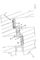
- FIG. 4 shows a further embodiment of the component which has a contact surface 8 for a Pleußuß 12.
- these components are pins 11, which are arranged in a bore within the crankshaft. At their ends, the pins 11 each have the contact surfaces 8, which limit the axial play of the big end 12.
Landscapes
- Engineering & Computer Science (AREA)
- General Engineering & Computer Science (AREA)
- Ocean & Marine Engineering (AREA)
- Mechanical Engineering (AREA)
- Shafts, Cranks, Connecting Bars, And Related Bearings (AREA)
Abstract
Description
- Die vorliegende Erfindung betrifft eine Kurbelwelle für einen Boxermotor mit Kurbelwellengehäuselagerungen und Pleuellagerungen, wobei jede Pleuellagerung eine axiale Anlauffläche aufweist. Des weiteren betrifft die vorliegende Erfindung einen Boxermotor aufweisend die erfindungsgemäße Kurbelwelle.
- Die gattungsgemäße Kurbelwelle für Boxermotoren ist aus dem Stand der Technik beispielsweise der
DE 35 21 667 , derDE 10 2004 035 025 A1 sowie derEP 1 207 292 bekannt. Die dort beschriebenen Kurbelwellen haben jedoch den Nachteil, dass sie einen vergleichsweise großen Kolbenversatz aufweisen; d. h. dass der axiale Versatz zwischen den beiden Kolben vergleichsweise groß ist. Dadurch erhöht sich die Baulänge und das Gewicht der Kurbelwelle bzw. des Kurbelwellengehäuses und damit des gesamten Motors. Darüber hinaus treten größere auszugleichende Kräfte bzw. Momente auf. - Es war deshalb die Aufgabe der vorliegenden Erfindung, eine Kurbelwelle zur Verfügung zustellen, die die Nachteile des Standes der Technik nicht aufweist.
- Gelöst wird die Aufgabe mit einer Kurbelwelle für einen Boxermotor mit Kurbelwellengehäuselagerung und Pleuellagerung, wobei jede Pleuellagerung eine axiale Anlauffläche aufweist und ein die axiale Anlauffläche aufweisendes, separates Bauteil an der Kurbelwelle angeordnet ist.
- Bei der erfindungsgemäßen Kurbelwelle ist es demnach möglich die Radienauslaufflächen, die sich an die Lagerflächen der Pleuele anschließen näher an der Mittellagerfläche anzuordnen. Dadurch befindet sich die Radienauslauffläche jedoch hinter der Mittellagerseitenfläche und kann dem Pleuel somit nicht mehr als Anlauffläche dienen. Diese Anlauffläche wird deshalb nach dem Bearbeiten der Lagerfläche und der Radienauslauffläche der Pleuellagerung nachträglich als separates Bauteil an der Kurbelwelle angeordnet.
- Durch die erfindungsgemäße Kurbelwelle ist es möglich, den axialen Versatz der Zylinder zu verkleinern. Dadurch verringert sich die Baulänge und das Gewicht der Kurbelwelle, des Kurbelgehäuses sowie des gesamten Motors. Die auszugleichenden Kräfte bzw. Momente sind bei der erfindungsgemäßen Kurbelwelle geringer als bei Kurbelwellen gemäß dem Stand der Technik. Dadurch verringert sich beispielsweise die Größe der Ausgleichsgewichte, die zur Erzielung der gewünschten Laufruhe des Motors benötigt werden.
- Erfindungsgemäß ist ein die axiale Anlauffläche aufweisendes, separates Bauteil an der Kurbelwelle angeordnet. Vorzugsweise ist das Bauteil im Bereich der Mittelwange der Kurbelwelle angeordnet. Ganz besonders bevorzugt weist das Bauteil zwei Anlaufflächen für zwei Pleuele auf.
- Vorzugsweise ist das Bauteil in die Kurbelwelle eingesetzt und/oder auf die Kurbelwelle aufgesetzt. Besonders bevorzugt besteht zwischen dem die Anlauffläche aufweisenden Bauteil und der Kurbelwelle eine Form-, Kraft- und/oder formschlüssige Verbindung. Beispielsweise kann das die Anlauffläche aufweisende Bauteil in die Kurbelwelle eingesteckt, eingepresst, eingeschraubt und/oder eingeklebt sein. Das Bauteil kann jedoch auch beispielsweise als Ring lediglich auf die Kurbelwelle aufgesetzt sein.
- Das die Anlauffläche(n) aufweisende Bauteil kann jedes beliebige dem Fachmann geläufige Bauteil sein. Vorzugsweise handelt es sich bei dem Bauteil jedoch um eine Hülse oder um einen oder mehrere Zapfen, die jeweils in eine Bohrung in der Kurbelwelle eingesetzt werden.
- Vorzugsweise erfolgt die Anordnung des Bauteils, das die Anlauffläche aufweist, an der Kurbelwelle, nachdem die Lagerflächen und die Radienauslaufflächen der Pleuellagerung bearbeitet, insbesondere geschliffen worden sind. Diese bevorzugte Ausführungsform der vorliegenden Erfindung hat den Vorteil, dass die Lagerflächen und insbesondere die Radienauslaufflächen ungehindert bearbeitet werden können. Dadurch lassen sich insbesondere im Bereich der Radienauslaufflächen sehr glatte Flächen mit geringen Toleranzen erzielen, was insbesondere für die Langlebigkeit der Kurbelwelle von großer Bedeutung ist, da ein Versagen der Kurbelwelle in der Regel im Bereich der Radienauslaufflächen erfolgt.
- Die erfindungsgemäße Kurbelwelle eignet sich insbesondere zum Einsatz in Boxermotoren.
- Ein weiterer Gegenstand der vorliegenden Erfindung ist deshalb ein Boxermotor aufweisend die erfindungsgemäße Kurbelwelle.
- Vorzugsweise handelt es sich bei dem Boxermotor um einen Zweizylindermotor.
- Im folgenden wird die Erfindung anhand der Figuren 1 bis 4 erläutert. Diese Erläuterungen sind lediglich beispielhaft und schränken den allgemeinen Erfindungsgedanken nicht ein. Die Erläuterungen gelten für beide Erfindungsgegenstände gleichermaßen.
- Figur 1
- zeigt eine Ausführungsform der erfindungsgemäßen Kurbelwelle.
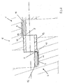
- Figur 2
- zeigt ein Detail der Kurbelwelle gemäß Figur 1.
- Figur 3
- zeigt die erfindungsgemäße Kurbelwelle mit einem Pleuel.
- Figur 4
- zeigt eine weitere Ausführungsform des Mittellagers gemäß Figur 1.
- Figur 1 zeigt die erfindungsgemäße Kurbelwelle 1 für einen zweizylindrigen Boxermotor. Die Kurbelwelle weist zwei äußere Kurbelwellengehäuselagerungen 2, 4 und eine Lagerung 3, das s. g. Mittelkurbelwellengehäuselager, auf. Des weiteren weist die erfindungsgemäße Lagerung zwei Pleuellagerungen 6, 7 auf, an denen die Pleuele (nicht dargestellt) gelagert sind. Im Bereich des Mittellagers 3 befindet sich die Mittelwange 5, die eine Bohrung aufweist, in die eine Hülse 13 eingesetzt, beispielsweise eingepresst, eingeschraubt oder eingeklebt, ist, deren Enden jeweils die Anlaufflächen 8 für die nicht dargestellten Pleuele zur Verfügung stellen.
- In Figur 2 ist der Bereich um die Mittelwange 5 detailliert dargestellt. In dieser Figur ist zu erkennen, dass die Pleuellagerungen 6, 7 jeweils Lagerflächen 9 aufweisen, die mit Lagern 14, die an den Pleuelfüßen 12 angeordnet sind, drehend zusammenwirken. An die Lagerflächen 9 schließen sich Radienausläufe 10 an, die so gestaltet sind, dass sie so nah wie möglich neben der Mittellagerfläche liegen. Dadurch befinden sich diese Radienauslaufflächen jedoch hinter der Mittellagergehäuseseitenflächen und können dem jeweiligen Pleuelfuß 12 nicht mehr als Anlauffläche dienen. Um dennoch eine Anlauffläche für den Pleuelfuß zur Verfügung stellen zu können, wird nach der Bearbeitung der Lagerfläche 9 sowie der Radienauslauffläche 10, beispielsweise durch Schleifen, die Hülse 13, die für beide Pleuellagerungen die Anlaufflächen 8 aufweist in eine Bohrung in der Kurbelwelle angeordnet, beispielsweise eingepresst.
- In Figur 3 ist die Kurbelwelle gemäß den Figuren 1 und 2 zusehen, wobei in dem vorliegenden Fall nicht nur der Pleuelfuß 12, sondern auch der gesamte Pleuel 16 sowie der dazugehörige Kolben 15 zu sehen ist. Der Fachmann versteht, dass bei einem fertig montierten Motor an der Pleuellagerung 7 ebenfalls ein Pleuel 16 und ein dazugehöriger Zylinder 15 angeordnet ist.
- Figur 4 zeigt eine weitere Ausführungsform des Bauteils, das eine Anlauffläche 8 für einen Pleulfuß 12 aufweist. In dem vorliegenden Fall sind diese Bauteile Zapfen 11, die in einer Bohrung innerhalb der Kurbelwelle angeordnet sind. An ihren Enden weisen die Zapfen 11 jeweils die Anlaufflächen 8 auf, die das axiale Spiel des Pleuelfußes 12 begrenzen.
-
- 1
- Kurbelwelle
- 2, 3, 4
- Kurbelwellengehäuselager
- 5
- Mittelwange
- 6, 7
- Pleuellagerung
- 8
- Anlauffläche
- 9
- Lagerfläche
- 10
- Radienauslauffläche
- 11
- Bauteil, Zapfen
- 12
- Pleuelfuß
- 13
- Bauteil, Hülse
- 14
- Lagerfläche des Pleuels 16
- 15
- Kolben
- 16
- Pleuel
Claims (8)
- Kurbelwelle (1) für einen Boxmotor mit Kurbelwellengehäuselagerungen (2 - 4) und Pleuellagerungen (6, 7), wobei jede Pleuellagerung (6, 7) eine axiale Anlauffläche (8) aufweist, dadurch gekennzeichnet, dass ein die axiale Anlauffläche (8) aufweisendes, separates Bauteil (11, 13) an der Kurbelwelle angeordnet ist.
- Kurbelwelle nach Anspruch 1, dadurch gekennzeichnet, dass das Bauteil (11, 13), vorzugsweise mit axialen Anlaufflächen (8) für zwei Pleuellagerungen (6, 7), im Bereich der Mittelwange (5) angeordnet ist.
- Kurbelwelle nach einem der voranstehenden Ansprüche, dadurch gekennzeichnet, dass das Bauteil (11, 13) in die Kurbelwelle (1) eingesetzt und/oder auf die Kurbelwelle aufgesetzt ist.
- Kurbelwelle nach einem der voranstehenden Ansprüche, dadurch gekennzeichnet, dass zwischen dem die Anlauffläche (8) aufweisenden Bauteil (11, 13) und der Kurbelwelle (1) eine form-, kraft- und/oder formschlüssige Verbindung besteht.
- Kurbelwelle nach einem der voranstehenden Ansprüche, dadurch gekennzeichnet, dass die Anlauffläche (8) Teil einer Hülse (13) oder eines Zapfens (11) ist.
- Kurbelwelle nach einem der voranstehenden Ansprüche, dadurch gekennzeichnet, dass die Pleuellagerung (6, 7) jeweils eine Lagerfläche (9) und eine Radienauslauffläche (10) aufweist und dass das Bauteil (11, 13) nach dem Bearbeiten der Lagerfläche (9) und der Radienauslauffläche (10) montiert ist.
- Boxermotor aufweisend eine Kurbelwelle nach einem der voranstehenden Ansprüche.
- Boxermotor nach Anspruch 7, dadurch gekennzeichnet, dass es ein 2-Zylinder-Motor ist.
Applications Claiming Priority (1)
| Application Number | Priority Date | Filing Date | Title |
|---|---|---|---|
| DE200510046500 DE102005046500A1 (de) | 2005-09-29 | 2005-09-29 | Kurbelwelle für einen Boxermotor |
Publications (3)
| Publication Number | Publication Date |
|---|---|
| EP1770286A2 true EP1770286A2 (de) | 2007-04-04 |
| EP1770286A3 EP1770286A3 (de) | 2008-03-26 |
| EP1770286B1 EP1770286B1 (de) | 2010-06-09 |
Family
ID=37560760
Family Applications (1)
| Application Number | Title | Priority Date | Filing Date |
|---|---|---|---|
| EP20060018626 Not-in-force EP1770286B1 (de) | 2005-09-29 | 2006-09-06 | Kurbelwelle für einen Boxermotor |
Country Status (3)
| Country | Link |
|---|---|
| EP (1) | EP1770286B1 (de) |
| DE (2) | DE102005046500A1 (de) |
| ES (1) | ES2343896T3 (de) |
Family Cites Families (5)
| Publication number | Priority date | Publication date | Assignee | Title |
|---|---|---|---|---|
| GB259065A (en) * | 1925-12-01 | 1926-10-07 | Charles Day | Improvements relating to crank shafts |
| FR718359A (fr) * | 1931-06-06 | 1932-01-23 | Montage de roulements sur vilebrequin | |
| DE959773C (de) * | 1954-02-20 | 1957-03-14 | Erich Kuenneth | Mit einem Waelzlager ausgestattetes Kurbelwellenhauptlager |
| DE1815037B2 (de) * | 1968-12-17 | 1972-02-17 | Fichtel & Sachs AG, 8720 Schwein fürt | Verfahren zur herstellung einer drehfesten verbindung einer welle eines zapfens od dgl mit einer von der welle dem zapfen od dgl durchsetzten anlaufscheibe |
| DE3738808A1 (de) * | 1987-11-15 | 1989-05-24 | Emitec Emissionstechnologie | Gebaute kurbelwelle |
-
2005
- 2005-09-29 DE DE200510046500 patent/DE102005046500A1/de not_active Withdrawn
-
2006
- 2006-09-06 DE DE200650007153 patent/DE502006007153D1/de active Active
- 2006-09-06 EP EP20060018626 patent/EP1770286B1/de not_active Not-in-force
- 2006-09-06 ES ES06018626T patent/ES2343896T3/es active Active
Also Published As
| Publication number | Publication date |
|---|---|
| ES2343896T3 (es) | 2010-08-12 |
| DE102005046500A1 (de) | 2007-04-12 |
| EP1770286A3 (de) | 2008-03-26 |
| DE502006007153D1 (de) | 2010-07-22 |
| EP1770286B1 (de) | 2010-06-09 |
Similar Documents
| Publication | Publication Date | Title |
|---|---|---|
| DE3886903T2 (de) | Kreuzkopf in Kombination mit einer Pleuelstange und einer Kolbenstange. | |
| DE60032522T2 (de) | Mehrstufiger Hochdruckkompressor | |
| EP2464867B1 (de) | Antriebsvorrichtung für oszillierende verdrängermaschinen | |
| DE69503090T2 (de) | Pleuelstange für Verbrennungsmotor | |
| DE102008059621A1 (de) | Lageranordnung für eine Kurbelwelle | |
| DE102010002980A1 (de) | Wellenbelastungsvorrichtung | |
| DE102010004593B4 (de) | Brennkraftmaschine mit variabler Verdichtung und einteiligen Anlenkpleueln | |
| DE3318215C2 (de) | ||
| DE102008009869A1 (de) | Kurbelwelle, insbesondere für eine Brennkraftmaschine | |
| EP1770286B1 (de) | Kurbelwelle für einen Boxermotor | |
| DE10153018A1 (de) | Kurbelwellenlager | |
| DE4337473C2 (de) | Kolben-Pleuel-Einheit | |
| DE102020110793A1 (de) | Kurbelwelle mit Ölversorgung | |
| DE10137267B4 (de) | Welle mit Ausgleichsmasse | |
| WO2002018787A1 (de) | Kolbenkompressor mit dynamisch massenausgeglichener kurbelwelle, insbesondere für schienenfahrzeuge (lösbare ausgleichsmasse) | |
| DE2352520C2 (de) | Hydrostatische Kolbenmaschine | |
| DE10046214C1 (de) | Fleuelstange, insbesondere Marinekopf | |
| CH718468B1 (de) | Kurbeltrieb zum Einsatz in einem Inline-Boxermotor. | |
| AT390309B (de) | Gebaute kurbelwelle | |
| WO2015158902A2 (de) | Pleuellagerung für einen luftverdichter eines luftfedersystems sowie kolbenkompressor | |
| DE10042214A1 (de) | Kolbenkompressor mit einem dynamischen Massenausgleich im Bereich der Kurbeltriebe, insbesondere für Schienenfahrzeuge (Ausgleichspleuel) | |
| EP0789139A2 (de) | Brennkraftmaschine mit einem angeflanschten Generator | |
| DE102019106313A1 (de) | Gebaute Kurbelwelle für eine Hubkolben-Brennkraftmaschine | |
| EP2370697B1 (de) | Kompressor | |
| DE10101227C1 (de) | Hubkolbenbrennkraftmaschine und Kurbelwelle hierfür |
Legal Events
| Date | Code | Title | Description |
|---|---|---|---|
| PUAI | Public reference made under article 153(3) epc to a published international application that has entered the european phase |
Free format text: ORIGINAL CODE: 0009012 |
|
| AK | Designated contracting states |
Kind code of ref document: A2 Designated state(s): AT BE BG CH CY CZ DE DK EE ES FI FR GB GR HU IE IS IT LI LT LU LV MC NL PL PT RO SE SI SK TR |
|
| AX | Request for extension of the european patent |
Extension state: AL BA HR MK YU |
|
| PUAL | Search report despatched |
Free format text: ORIGINAL CODE: 0009013 |
|
| AK | Designated contracting states |
Kind code of ref document: A3 Designated state(s): AT BE BG CH CY CZ DE DK EE ES FI FR GB GR HU IE IS IT LI LT LU LV MC NL PL PT RO SE SI SK TR |
|
| AX | Request for extension of the european patent |
Extension state: AL BA HR MK YU |
|
| RIC1 | Information provided on ipc code assigned before grant |
Ipc: F16C 3/08 20060101ALI20080220BHEP Ipc: F16C 3/10 20060101AFI20070108BHEP Ipc: F02B 75/24 20060101ALI20080220BHEP |
|
| 17P | Request for examination filed |
Effective date: 20080418 |
|
| 17Q | First examination report despatched |
Effective date: 20080519 |
|
| AKX | Designation fees paid |
Designated state(s): DE ES FR GB IT |
|
| GRAP | Despatch of communication of intention to grant a patent |
Free format text: ORIGINAL CODE: EPIDOSNIGR1 |
|
| GRAS | Grant fee paid |
Free format text: ORIGINAL CODE: EPIDOSNIGR3 |
|
| GRAA | (expected) grant |
Free format text: ORIGINAL CODE: 0009210 |
|
| AK | Designated contracting states |
Kind code of ref document: B1 Designated state(s): DE ES FR GB IT |
|
| REF | Corresponds to: |
Ref document number: 502006007153 Country of ref document: DE Date of ref document: 20100722 Kind code of ref document: P |
|
| REG | Reference to a national code |
Ref country code: ES Ref legal event code: FG2A Ref document number: 2343896 Country of ref document: ES Kind code of ref document: T3 |
|
| PLBE | No opposition filed within time limit |
Free format text: ORIGINAL CODE: 0009261 |
|
| STAA | Information on the status of an ep patent application or granted ep patent |
Free format text: STATUS: NO OPPOSITION FILED WITHIN TIME LIMIT |
|
| 26N | No opposition filed |
Effective date: 20110310 |
|
| REG | Reference to a national code |
Ref country code: DE Ref legal event code: R097 Ref document number: 502006007153 Country of ref document: DE Effective date: 20110309 |
|
| REG | Reference to a national code |
Ref country code: FR Ref legal event code: PLFP Year of fee payment: 11 |
|
| REG | Reference to a national code |
Ref country code: FR Ref legal event code: PLFP Year of fee payment: 12 |
|
| PGFP | Annual fee paid to national office [announced via postgrant information from national office to epo] |
Ref country code: FR Payment date: 20170925 Year of fee payment: 12 Ref country code: DE Payment date: 20170915 Year of fee payment: 12 Ref country code: GB Payment date: 20170925 Year of fee payment: 12 Ref country code: IT Payment date: 20170926 Year of fee payment: 12 |
|
| PGFP | Annual fee paid to national office [announced via postgrant information from national office to epo] |
Ref country code: ES Payment date: 20171003 Year of fee payment: 12 |
|
| REG | Reference to a national code |
Ref country code: DE Ref legal event code: R119 Ref document number: 502006007153 Country of ref document: DE |
|
| GBPC | Gb: european patent ceased through non-payment of renewal fee |
Effective date: 20180906 |
|
| PG25 | Lapsed in a contracting state [announced via postgrant information from national office to epo] |
Ref country code: DE Free format text: LAPSE BECAUSE OF NON-PAYMENT OF DUE FEES Effective date: 20190402 Ref country code: IT Free format text: LAPSE BECAUSE OF NON-PAYMENT OF DUE FEES Effective date: 20180906 |
|
| PG25 | Lapsed in a contracting state [announced via postgrant information from national office to epo] |
Ref country code: FR Free format text: LAPSE BECAUSE OF NON-PAYMENT OF DUE FEES Effective date: 20180930 |
|
| REG | Reference to a national code |
Ref country code: ES Ref legal event code: FD2A Effective date: 20191030 |
|
| PG25 | Lapsed in a contracting state [announced via postgrant information from national office to epo] |
Ref country code: GB Free format text: LAPSE BECAUSE OF NON-PAYMENT OF DUE FEES Effective date: 20180906 |
|
| PG25 | Lapsed in a contracting state [announced via postgrant information from national office to epo] |
Ref country code: ES Free format text: LAPSE BECAUSE OF NON-PAYMENT OF DUE FEES Effective date: 20180907 |