EP1769993A2 - Fahrzeugsteuerungsystem - Google Patents
Fahrzeugsteuerungsystem Download PDFInfo
- Publication number
- EP1769993A2 EP1769993A2 EP06020404A EP06020404A EP1769993A2 EP 1769993 A2 EP1769993 A2 EP 1769993A2 EP 06020404 A EP06020404 A EP 06020404A EP 06020404 A EP06020404 A EP 06020404A EP 1769993 A2 EP1769993 A2 EP 1769993A2
- Authority
- EP
- European Patent Office
- Prior art keywords
- node
- status
- nodes
- section
- vehicle
- Prior art date
- Legal status (The legal status is an assumption and is not a legal conclusion. Google has not performed a legal analysis and makes no representation as to the accuracy of the status listed.)
- Granted
Links
Images






















Classifications
-
- B—PERFORMING OPERATIONS; TRANSPORTING
- B60—VEHICLES IN GENERAL
- B60W—CONJOINT CONTROL OF VEHICLE SUB-UNITS OF DIFFERENT TYPE OR DIFFERENT FUNCTION; CONTROL SYSTEMS SPECIALLY ADAPTED FOR HYBRID VEHICLES; ROAD VEHICLE DRIVE CONTROL SYSTEMS FOR PURPOSES NOT RELATED TO THE CONTROL OF A PARTICULAR SUB-UNIT
- B60W50/00—Details of control systems for road vehicle drive control not related to the control of a particular sub-unit, e.g. process diagnostic or vehicle driver interfaces
- B60W50/02—Ensuring safety in case of control system failures, e.g. by diagnosing, circumventing or fixing failures
- B60W50/0205—Diagnosing or detecting failures; Failure detection models
Definitions
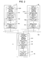
- the status evaluation result transmitting/receiving section x2 has the status evaluation result storage section x201 for use to store the node evaluation result made by the own node and node evaluation result received from the other nodes.
- status decisions made by node 1 and stored in a buffer 141 in the status evaluation result storage section 1201 of node 1 are delivered to all the other nodes in the same network except node 1 via the network 100 and stored in buffers x41 (241, 341, ..., n41, in this case) in the status evaluation result storage sections x201 of the other nodes.
- buffers x41 (241, 341, ..., n41, in this case
- Step S180 results of ID may be reported directly. Alternatively, they may be reported via a failure counter as described later.
- the processing is finished in Step S190.
- the transmit data is prepared by appending various fault detection codes Csn and the like to the decisions Sn made in communication cycle i.
- the receiving nodes receive the transmit data in the rcv processes Sx4l, Sx42, ..., Sx4n), determine the status of the transmitting nodes by analyzing the fault detection codes Csn, and store the decisions as own node's status decisions in communication cycle i. If the decisions are normal, the receiving nodes stores the status decisions Sn made by the other nodes (in communication cycle i) and contained in the transmit data.
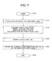
- each node transmits node evaluation result made by the own node and receives node evaluation result made by the other nodes (status decision exchange: EXD), and in the second half, each node identifies any failed node (ID).
- EXD status decision exchange
- ID failed node
- the own-node evaluation result made by the own nodes themselves are not used in the identification of failed nodes.
- decisions made by node 2 to node n are used in fault determination about node 1 and that evaluation results made by node 1 and nodes 3 to n are used in fault evaluation about node 2. This is because the accuracy of evaluation may be reduced if a own-node status decision made by any failed node is used in a majority decision, meaning the use of an abnormal decision in the majority decision.
- each node should determine its own node status and send (broadcasts) it to other nodes even if the result is not used in a majority decision. This is because then application programs running on the node can select control logic and the like with the knowledge of whether or not the node is out of order.
- Fig. 10 shows a configuration of the failed-node identification section x3, which is assumed to belong to node 1 for convenience of explanation.
- the failed-node identification sections x3 (23, ..., n3) of the other nodes 2 to n have the same configuration.
- the failed-node identification section 13 (of node 1) consists of a failed-node identification algorithm execution section 131, failure counter 132, failure counter limit-over checking section 133, failure counter limit-value setting section 134, and node failure flag storage section 135.
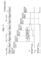
- Fig. 11 shows an example of operation of the failure counter 132.
- Fig. 11 shows a case in which fault 1 occurs in node 2 at a time later than send time at node 2 in communication cycle i and continues until after send time at node 2 in communication cycle i+4. It is assumed that the failure counter's limit value for fault 1 in node 2 is three.
- communication cycle i+1 a fault detected in node 2 by the nodes other than node 2 is subjected to an EXD process in the first half of communication cycle i+2 and is confirmed in an ID process in the second half of communication cycle i+2, causing the appropriate counter to be incremented.
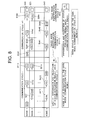
- Step 4 determines whether the number of other nodes which determine that fault 1 has occurred is equal to or larger than the diagnostic threshold X, i.e., whether the number of other nodes which agree with node 2 is equal to or larger than the diagnostic threshold X. If it is equal to or larger than the diagnostic threshold X, diagnosis Diag3 is given as when fault 1 has occurred in node 2.
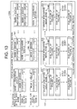
- Figs. 15 and 16 show two examples by putting together the examples of individual components described so far. They show transmit timing and transmit data from each node; timing chart of fault occurrences; and changes in the status evaluation result storage section x201, failure counter x32, and node failure flag x35 of each node on the occurrence of faults. Double lines are drawn around transmit data. Only status decisions are shown as the transmit data for the sake of simplicity, but it is assumed that actually control data is transmitted together with the status decisions. It is assumed that the number of nodes in the network is 4, that the diagnostic threshold X set by the control logic execution section for the failed-node identification algorithm execution section x31 is 3, and that the limit value of the failure counter is 2.
- a CPU fault occurs in node 3 during time slot 1 of communication cycle i+1, causing software to malfunction.
- Node 3 is supposed to transmit, during slot 3, the status decision made in communication cycle i, but the node failure check code appending section 38 cannot increment the serial number due to the CPU fault. Consequently, upon receiving the status decision from node 3, the other nodes detects that the serial number is not incremented and determines that a serial number error has occurred in node 3. At this time, however, even if the fault of node 3 is detected, each detecting node cannot identify accurately whether it is a fault of node 3 or misjudgment of its own because the determination is made by the detecting node alone.
- nodes 1, 2, and 4 transmit their own status decisions 0080 (which indicate the serial number error in node 3).
- each node executes the failed-node identification algorithm shown in Fig. 14 using the status decisions made by nodes 1, 2, and 4. Consequently, the serial number error in node 3 is confirmed and nodes 1, 2, and 4 increments the failure counter E1_3. Since the fault in node 3 persists in communication cycle i+2 and later, the failure counter E1_3 is incremented similarly in communication cycle i+3. Consequently, the failure counter value reaches the limit value and the appropriate node failure flag is set.
- the frame error here means that a received frame contains an error defined by a communication protocol such as a format error, CRC error, serial number error, or check sum error.
- failure counter values may not coincide completely among the nodes and the timing to report the fault to the control applications may vary among the nodes.
- the control applications perform backup control based on a fault notification, and the timing to change from normal control to backup control will vary from node to node, which may make it impossible to perform backup control properly. For example, if some transient error occurs during processing by the failed-node identification section in a certain node, the failure counter cannot be incremented or decremented properly and its value will deviated from the failure counter values in the other nodes. In the case of a halfway reset, the failure counter is initialized to 0.
- the transmit frame consists of the node evaluation result S1 described above and a fault notification synchronization flag field Sync1.
- the fault notification synchronization flag field Sync1 consists of whether the counter value of the failure counter in each node has reached "the limit value - 1" (1) or not (0).
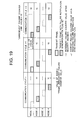
- nodes 1 and 4 transmit a frame with a bit set in the node-3 "Frame Unreceived" failure counter E4_3 of the fault notification synchronization flag field Sync1 as shown in Fig. 18.
- node 1 can correct the limit value to 9 immediately in the communication cycle during which it participates in the communication and shift to backup control instead of continuing a normal control process apart from nodes 2 and 4 until the failure counter reaches the limit value of 10.
- Fig. 20 shows a case in which node 4 transmits a fault notification synchronization frame related to a node-3 "Frame Unreceived" fault in communication cycle i+1 and node 2 receives it but node 1 cannot.
- Node 2 corrects the failure counter value to 9 in this communication cycle, and notifies the control application of the fault after a failed-node identification process. Consequently, node 2 transmits a fault notification synchronization frame in the next communication cycle i+2. Since node 1 can receive the fault notification synchronization frame from node 2 or 4, it can shift to backup control in the next communication cycle like the other nodes even though it fails to receive the fault notification synchronization frame from node 4 in communication cycle i+1.
- the fault notification synchronization frame is transmitted in the first communication cycle after the failure counter value reaches "the limit value - 1," but it may be transmitted in the first communication cycle after the failure counter reaches the limit value, i.e., the fault is reported to the control application.
- the timings of fault notifications may vary among nodes by a period equal to one communication cycle, and thus the duration of one communication cycle should be made sufficiently smaller than the time constant of vehicle motion. Also, in Fig.
- the packing process and unpacking process are performed by the communication processing middleware 1600; and the network fault detection code appending process, network fault determination process, frame processing, and data transmitting/receiving process are performed by the communication controller driver 1700 and communication controller 1200.
- the communication transceiver 1300 corresponds to the network access section x6.
- the failed-node monitoring middleware 1500 performs the network fault detection code appending process, other-node status determination process, and failed-node identification process. It has APIs (Application Program Interfaces) to provide node status information to the control application 1400. At a lower level, it provides an interface between the communication processing middleware 1600 and communication controller driver 1700. According to this example, since the failed-node monitoring function is implemented by means of middleware, the control application can acquire node status information using a predetermined API, and thus it is possible to improve development efficiency of control application software.
- APIs Application Program Interfaces
- the integrated vehicle motion control ECU 910 calculates the steering angle, braking forces, driving force, and the like for vehicle travel control based on signals from a steering angle sensor Sen1, brake pedal position sensor Sen2, accelerator pedal position sensor Sen3, and sensors (e.g., an acceleration sensor, yaw rate sensor, and wheel speed sensor: not shown) which detect vehicle conditions.
- a steering angle sensor Sen1 brake pedal position sensor Sen2, accelerator pedal position sensor Sen3, and sensors (e.g., an acceleration sensor, yaw rate sensor, and wheel speed sensor: not shown) which detect vehicle conditions.
- each node has a receive data storage section 14 which stores control data received from the other nodes and transmit data storage section 15 which stores control data subjected to arithmetic operations by the control logic execution section and transmitted to the other nodes.
- the control data D2 is stored in the receive data storage section 14 and the status evaluation result S2 (self-diagnostic result + decisions about nodes 1 and 3 to n) made by node 2 are stored in the status evaluation buffer 142.
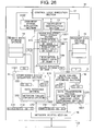
- the other-node status evaluation section 1101 may be configured to determine the status of node 2 by checking not only the status decisions S2 made by node 2, but also the integrity of the control data D2. This will make it possible to detect logical data errors not only in the data link layer, but also in the application layer although details will be described later (Fig. 26).
- the other-node status evaluation section 1101 determines the status of nodes 3 to n, stores decisions Eln in the own node's status evaluation result storage buffer 141, and saves the status decisions from the other nodes in predetermined buffers 143 (not shown) to 14n. If there is nothing wrong with the status of nodes 3 to n, control data D3 to Dn from nodes 3 to n are stored in the receive data storage section 14. Incidentally, processes of the failed-node identification section 13 and own-node status determination section 1102 are the same as the examples illustrated in Fig. 3.
- the data transmission section 1203 puts together the control data D1 and own node's status decisions S1 into a single set of communication data and appends a header to it and makes the network failure check code appending section 1901 append a network fault detection code CP1 for use to detect any fault occurring on the network 100 while the communication data is delivered to other nodes.
- the network failure checking section 1902 of the data receiving section 1202 determines, using the network fault detection code CP2 appended by the network failure check code appending section 2901 of node 2 and data part other than CP2, whether a data change such as a bit flip has not occurred on the network 100 during delivery of the communication data.
- the other-node status evaluation section 1101 checks node 2 for any fault using the codes CD2 and CS2 appended by the node failure check code appending section 28 of node 2 as well as data D2 and S2 and stores a resulting decision E11 and a decision E13 from the network failure checking section 1902 in a region for status of node 2 in the own node's status evaluation result buffer 141.
- the network failure checking section 1902 may store the decision by accessing the own node's status evaluation result buffer 141 directly.
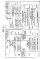
- Fig. 27 Details of the node failure check code appending section, other-node status evaluation section, data transmission section, and data receiving section are shown in Fig. 27. Components are the same as those in Fig. 6 unless otherwise stated.
- Fig. 27 shows an example in which node 2 transmits data with fault detection code appended and node 1 receives the data and checks for any fault.
- the node failure check code appending section 28 has a serial number appending section 281 for the control data D2, check sum appending section 282, serial number appending section 283 for the status decisions S2 made by node 2, and check sum appending section 284.
- the serial number appending sections 281 and 283 increment a serial number appended to data each time data is transmitted.
- the check sum appending sections 282 and 284 find a sum by totaling a serial number region and data region in bytes, bit-flip the sum, and append the resulting value as a check sum.
- a packing/frame processing section 2903 of the data transmission section 2203 packs D2 and S2 to which fault detection codes have been appended into a set of communication data and perform communication protocol processing such as appendage of a header. Subsequently, a known CRC (cyclic redundancy check) code is appended to check whether the communication data has not been corrupted on the network 100 due to a bit flip or the like.
- CRC cyclic redundancy check
- the other-node status evaluation section 1101 checks the data D2 and S2 separated by an unpacking/frame processing section 1904' of the data receiving section 1202 by making a check sum checking section 11012, serial number checking section 11013, and differential data checking section 11014 check the integrity of the control data D2 itself and a check sum checking section 11015 and serial number checking section 11016 check S2, and thereby determines the status of node 2.
- the check sum checking sections 11012 and 11015 find a sum by totaling the serial number region and data region in bytes, bit-flip the sum, and check whether the resulting value agrees with the check sum appended to the data by the check sum appending section of the transmitting end.
- the serial number checking sections 11013 and 11016 check whether the serial number appended to the current receive data is incremented from that of the previous receive data.
- This configuration makes it possible to transmit and receive control data needed for vehicle control while performing the diagnostic process according to the present invention. Also, it offers the same advantages as the first example described with reference to Figs. 5 and 6. Besides, since the differential data abnormality checking section 11014 checks the integrity of the control data D itself, it is also possible to diagnose abnormalities in the application layer.
- Another method for transmitting control data x when the control cycle is longer than the communication cycle involves appending the control data Dx only in communication cycles in which the control data Dx is updated and transmitting only status decisions Sx in communication cycles in which the control data Dx is not updated. This method can reduce the amount of data to be communicated, and thus implement an inexpensive system by keeping the traffic volumes of the networks 100 and 100A lower than can the first method.
- control data Dx and status decisions Sx are transmitted/received as a single unit (in the same slot) as shown in Fig. 28A (in Figs. 28A and 28B, double lines are drawn around transmit data), the control data Dx and status decisions Sx may be transmitted/received in separate slots.
- Fig. 28B the control data Dx is transmitted and received in the first half of each communication cycle and the status decisions Sx are transmitted and received in the second half of each communication cycle. Consequently, in Fig. 28B, only data needed for control performed in the own node have to be received in a control data transmitting/receiving phase in the first half of each communication cycle whereas in Fig. 28A, the transmit data from all nodes must be received during the entire period of each communication cycle. In this case, in the configuration shown in Fig. 26, the transmission/reception of the status decisions Sx and transmission/reception of the control data Dx are performed separately.
- the local ECU checks a brake control ECU 1 for any fault in Step 13 based on the status information about remote ECUs acquired in Step 11. If the brake control ECU 1 is normal, the local ECU performs regular control--motor control based on braking force command values received from the brake control ECU--in Step 14A. If the brake control ECU 1 is failed, the local ECU checks in Step 15 whether any of brake motor control ECUs is failed. If there is nothing wrong with any brake motor control ECU, the local ECU goes to Step 17C to calculate braking force command values for four-wheel brake control based on the brake pedal position received from the brake pedal ECU 2. If any of the brake motor control ECUs is failed, the local ECU locates a faulty spot in Step 16.
- status decisions are received from all the nodes in the network and all the nodes are placed under fault monitoring for identification of failed nodes.
- increases in the number of nodes are expected to lead to increased reception in each node and amounts of computation by the failed-node identification algorithm execution section 131.
- these processes when performed by software, will result in an increased CPU processing load.
- Fig. 31 shows an embodiment of data transmission and reception among nodes in one communication cycle when a system of eight nodes in total is divided into mutually monitoring groups of four nodes--group A and group B.
- Group A consists of nodes A1 to A4 while group B consists of nodes B1 to B4.
- the black circles in the figure indicate receiving nodes of each frame transmitted by each node.
- the dotted lines indicate intra-group communication and solid lines indicate inter-group communication.
- nodes transmit the same data both in group A and group B as shown in Fig. 31.
- This is intended to provide for situations in which a fault occurs in one node disabling the node to transmit a frame or in which transmit data contains an error, so that information from the remaining two nodes in good order can be used.
- all the nodes receive node status data on the remote group, but this is not necessary if node status in the remote group does not affect control logic executed in the own node.
- the nodes in group A transmit, in turns, node status data on the group-A nodes, together with control data if necessary. Also, they determine node status by monitoring the frames.
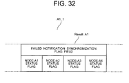
- Frame A1_2 transmitted by node A1 in slot 7 consists of node evaluation result SA1 about the nodes in group A, fault notification synchronization flag field SyncAl, and control data DA1 as shown in Fig. 33.
- a detailed configuration and generation method of the node evaluation result and fault notification synchronization flag field are the same as in the first example.
- nodes B3 and B2 receive transmit frames from nodes A1 and A4, respectively, and they extract and use only the control data, but not the node evaluation result of the group-A nodes.
- Fig. 34 shows an example in which fault notification synchronization flag fields Sync are received from the nodes in the remote group, thereby eliminating the intra-group node status exchange in the first half of the communication cycle shown in Fig. 31.
- the group-A nodes extract SyncBx from frames transmitted from nodes B1 and B3.
- the failure counter reaches the limit value, since the bit of the appropriate fault factor for the appropriate node is set to 1 in the fault notification synchronization flag field Sync, the node status in the local group can be reported to the nodes in the remote group using this bit.
- Step S100 processing is started.
- Step S110 each node determines node status independently. This process is the same as the MON process according to the first example.
- Step S120 the decisions made in Step S110 are transmitted (broadcasted) to the other nodes in the group. Also, each node receives node evaluation result made by the other nodes.
- the process in Step S120 is the same as the EXD process according to the above example.
- Step S140 based on the status decisions (MON results) made by itself and other nodes in Step S120, each node establishes the presence or absence of each type of fault on a node by node basis only regarding the m nodes in the group assigned to the own node.
- ID1 The process in Step S140 is designated as ID1, which differs from ID according to the above example in that the nodes checked by the own node is limited to m nodes.
- Step S170 the nodes monitored in ID1 are changed.
- Step S180 node fault information is reported as in the above example.
- Step S190 the processing is finished.
- Steps S100 to S190 node status monitoring is continued.
- This example reduces the processing load of the CPU and communication controller compared to the above examples because each node need to receive status decisions (MON results) from only m nodes assigned to it (status decisions made by nodes other than the assigned nodes do not have to be received from the beginning or may be discarded without processing after reception) and make status decisions (ID1 results) about only m nodes. This makes it possible to reduce manufacturing costs of ECUs and spare other processes part of CPU capacity.
- Step S170 Each node is assigned m nodes so that all the nodes in the group will be checked in ID1.
- Step S170 the nodes assigned to each node for ID1 are changed each time or periodically, so that even if a fault occurs in a node making it impossible to perform all or part of Steps S100 to S190, it will be possible to prevent a situation in which ID1 of a specific node would never be performed and consequently no status decision would be transmitted (EXD2).
- Step S170 is important in maintaining reliability of the node status monitoring function although it is not essential.
- the failed-node identification algorithm in the above example corresponds to ID1 + EXD2 + ID2.
- Figs. 36 and 37 show a status evaluation result storage section and failed-node identification section based on the decision broadcasting method.
- Fig. 36 the region in which status decisions (MON results) are stored is limited compared to the one in Fig. 4.
- the only region is a status evaluation result storage section 1420 for an assigned node, i.e., a buffer for status decisions about node 2.
- Status decisions about nodes other than node 2 are either rejected, or discarded even if received.
- an assigned-node status determination section 131a makes a status determination (ID1) about node 2 based on data in the assigned-node status evaluation result storage section 1420.
- ID1 is sent to a status decision adjustment section 131b as well as to the other nodes (EXD2).
- the status decision adjustment section 131b identifies any failed node (ID2) based on the status decisions (ID1 results) made by the own node and status decisions (ID1 results) received (EXD2) from the other nodes (nodes 2 to n).
- the nodes about which status determinations (ID1) are made by the other nodes are node 1 and nodes 3 to n.
- the status decision adjustment section 131b consolidates the status decisions (ID1 results) into a single status decision by a majority decision or prioritization.
- m 1 as in this example, the ID1 result is used directly as an ID2 result.
- status decisions are consolidated into a single status decision by giving priority to the own node's status decision over the status decisions (ID1 results) made by the other nodes.
- This example can reduce required buffer capacity compared to the first example (Fig. 4), and thereby reduce manufacturing costs of ECUs.
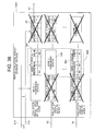
- Fig. 38 shows an example of a communication schedule according to the decision broadcasting method.
- Each node makes status determinations (MON) in a communication cycle i.
- EXD status determinations
- each node makes status determinations (ID1) about the nodes assigned to it.
- the nodes exchange the status decisions about the assigned nodes (EXD2).
- any failed node is identified (ID2).
- Steps S100 to S190 the processes may be performed concurrently.
- an MON process is performed in communication cycle i, and in the next communication cycle i+1, EXD and ID1 processes are performed on the MON results and an MON process is performed newly.
- communication cycle i+2 the ID1 results produced in communication cycle i+1 are subjected to EXD and ID1 processes, the MON results produced in communication cycle i+1 are subjected to EXD and ID1 processes, and an MON process is performed newly.
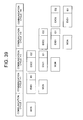
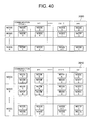
- Fig. 40 shows an example of changed schedule of assigned nodes in ID1 of each node. That is, the schedule indicates the nodes whose status each node should determine in ID1 in each communication cycle and whose status decisions each node should transmit to the other nodes in the next communication cycle. This corresponds to the process in Step S170.
- Node 1 is assigned to determine the status of node 2 in communication cycle i, node 3 in communication cycle i+1, and node n in communication cycle i+n-1. Coming full circle, it returns to node 2 in communication cycle i+n to repeat the rotation.
- Subject nodes are assigned to nodes 2 to n in such a way that the status of all the nodes will be determined in a communication cycle.
- Node 2 is assigned to monitor node 3 in communication cycle i, node 4 in communication cycle i+1, and node 1 in communication cycle i+n-1.
- Node n is assigned to monitor node 1 in communication cycle i, node 2 in communication cycle i+1, and node n-1 in communication cycle i+n-1. Consequently, even if each node monitors a single node in ID1, it is possible to check all the nodes for a fault in every communication cycle.
- the schedule 2010 is designed for this purpose. As ID1 subject nodes, node 1 checks nodes 2 and 3 in communication cycle i, nodes 3 and 4 in communication cycle i+1, nodes n and 2 in communication cycle i+n-1. Coming full circle, it returns to nodes 2 and 3 in communication cycle i+n to repeat the rotation.
- the schedules 2000 and 2010 may be retained as tables in a memory or other storage device, Schedules with such regularity can be calculated using a simple mathematical expression. In that case, for example, the node number of a node monitored by node 1 in the schedule 2000 can be determined by adding 1 to the remainder left after the given communication cycle is divided by n - 1.
- EXD which in this case, includes the ID1 results produced in communication cycle i, and thus combines EXD2
- the other nodes detect that the serial number is not incremented and determine that a serial number error has occurred in node 3 (MON in communication cycle i+1).
- each detecting node cannot determine whether it is a fault of node 3 or misjudgment of its own because the determination is made by the detecting node alone.
- nodes 1, 2, and 4 transmit their status decisions (MON results) 0080 (which indicates the serial number error in node 3) together with the status decisions (ID1 results) made in communication cycle i+2 (EXD).
- node 2 determines the status of node 3 (ID1), determines the presence or absence of each type of fault, and confirms the serial number error in node 3.
- node 2 transmits the status decision (ID1 result) about node 3 together with the status decision (MON result) made in communication cycle i+2 (EXD2).
- Each node on the network is assigned nodes on whose behalf it should make status determination (ID1) as well as nodes whose status it should determine (ID1).
- ID1 status determination
- ID1 status determination
- Step S200 processing is started.
- Step S210 m nodes assigned to each node for status determination are rotated. The rotation corresponds to changes in assigned nodes in the schedules 2000 and 2010.
- Steps S220 to S250 are carried out for each substituted node.
- One substituted node is assumed to be node a.
- Step S230 it is checked whether node a is failed.
- the fault detection is based on status determination (MON) by the node itself. If node a is failed, the flow goes to Step S240. Otherwise, the flow goes to Step S250.
- MON status determination
- Fig. 43 shows an example in which the flow in Fig. 42 is applied to actual network nodes.
- a timing chart 2020 shows nodes assigned to each node on the network for status determination (ID1) in each communication cycle.
- a schedule 2030 shows a node on whose behalf each node should make status determination (ID1) if necessary in each communication cycle.
- node 4 which is supposed to substitute for node 1 according to the schedule 2030 makes status determination (ID1) of node 3 originally assigned to node 1 for status determination.
- nodes 2, 3, and 4 also find node 1 faulty. Consequently, node 3 which is supposed to substitute for node 1 according to the schedule 2030 makes status determination (ID1) of node 4 originally assigned to node 1 for status determination.
- a design tool is used to create software which performs the above processes running on an ECU.
- the design tool is a software product running on a general-purpose computer or the like and is used by the user to make settings for network configuration, communication scheduling, task scheduling, and the like.
- a software product has a GUI (Graphical User Interface) and allows the user to design visually on a screen using input devices such as a keyboard and mouse.
- the design tool outputs source files including a header file based on the user settings.
- source files are combined with another source-file/object-file library and the like and passed through a compiler/linker, an executable program which runs on an ECU is generated.
- possible embodiments of the node status monitoring function according to the present invention include middleware.
- Fig. 44 shows a screen example of the design tool.
- the screen consists of a network configuration setting section 2100, network component selection area 2150, and main network setting section 2200.
- Communication lines N10A and N10B are laid in the network configuration setting section 2100 so that nodes 1 to 5 will be connected to them in a bus topology. That is, the network uses duplex communication paths of channel A and channel B.
- the network configuration is set and edited by the user by selecting and laying out (dragging and dropping) elements such as nodes and communication lines in the network component selection area 2150.
- Such a setting and editing method is adopted commonly by design tools, and detailed description thereof will be omitted.
- this design tool understands that the node status monitoring function will not be used and disables settings (rejects inputs) related to node status monitoring, and consequently items related to node status monitoring will not be contained in outputted source files and the like.
- this design tool enables setting inputs related to node status monitoring, and consequently items related to node status monitoring will be contained in outputted source files and the like.
- “Mutual Monitoring of all Nodes” is a mode in which all the network nodes in the network configuration setting section 2100 monitor each other. That is, each node makes status determinations (MON), exchanges status decisions with other nodes (EXD), and makes node status determinations (ID). This mode is reflected in content of outputted source files and the like.
- “Mutual Monitoring within Group” is a mode in which the network nodes are divided into groups and all the nodes in each group monitor each other.
- Broadcast Decisions is a mode in which each node in the group makes independent status determinations (MON) about all the other nodes in the group, but makes node status determinations (ID1) about only m other nodes in the group and decisions (ID1 results) are exchanged and shared among the network nodes.
- MON independent status determinations
- ID1 node status determinations
- “Advanced” is a mode which allows details of a node status monitoring mode to be specified. It allows node-by-node specification of detailed items, including "Node Status Monitoring Group” which is used when each node makes independent status determination (MON) and shares the results with the other nodes (EXD), information about the nodes assigned for status determination (ID1), an option as to whether to transmit (or broadcast) status decisions (ID1 results) to the other nodes, and an option as to whether to identify a failed node (ID2) by receiving status decisions (ID1 results) from the other nodes in and out of the group.
- Node Status Monitoring Group which is used when each node makes independent status determination (MON) and shares the results with the other nodes (EXD)
- ID1 information about the nodes assigned for status determination
- ID1 results information about the nodes assigned for status determination
- ID1 results an option as to whether to transmit (or broadcast) status decisions
- ID2 an option as to whether to identify a failed node
- the “Advanced” mode may become equivalent to "Mutual Monitoring of all Nodes,” “Mutual Monitoring within Group,” “Broadcast Decisions,” or the like depending on specified settings.
- the node status monitoring group is set to include all the nodes on the network and node status determinations (ID1) are set not to be transmitted (the settings of nodes assigned for status determination and the option as to whether to identify a failed node (ID2) become meaningless and thus are automatically disabled), the results become equivalent to "Mutual Monitoring of all Nodes.”
- the node status monitoring group is set to include only n nodes on the network and node status determinations (ID1) are set not to be transmitted, the results become equivalent to "Mutual Monitoring within Group.” That is, the "Advanced” mode includes all the other modes except "No Monitoring.”
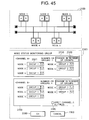
- a screen appears allowing the user to make group settings and monitoring condition settings for node status monitoring.
- Fig. 45 shows an example of a screen used to specify node status monitoring groups on the basis of nodes
- Fig. 46 shows an example of a screen used to specify node status monitoring groups on the basis of groups
- Fig. 47 shows an example of a screen used to specify detailed conditions of a node status monitoring group (e.g., group 1 on channel A).
- the three screens can be switched using tabs.
- a button 2330 an input field for the number of node status monitoring groups appears, allowing the user to change the number of node status monitoring groups.
- the number of node status monitoring groups on channel A is 2 and available group names in the node status monitoring group drop-down list boxes is "Group 1" and "Group 2.” If the number of node status monitoring groups is reduced and a group which has been specified in a node status monitoring group drop-down list box is no longer available, it is considered that the given node has no setting of a node status monitoring group.
- the channel B setting section 2350 is almost the same as the channel A setting section 2310. However, if the user checks a radio button 2360, inputs related to channel B, i.e., entries in the node status monitoring group drop-down list boxes 232x are disabled (inputs re rejected) and the same settings as those for channel A apply.
- the channel A setting section 2410 has member node text boxes 242x for use to specify nodes which should belong to a node status monitoring group x (2421 is illustrated in Fig. 46).
- the nodes whose names are entered in a member node text box belong to the given node status monitoring group.
- the same results can be obtained by dragging and dropping desired nodes among the nodes N101A to N105B from the network configuration setting section 2100 to a member node text box 242x or by clicking a desired member node text box 242x to select a group to edit (the group name is displayed in reverse video) and then clicking desired nodes among the nodes N101A to N105B in the network configuration setting section 2100.
- the user can delete the node name.
- a node status monitoring group condition setting screen 2500 consists of a channel A setting section 2510, button 2580, and button 2590.
- the buttons 2580 and 2590 are equivalent to the buttons 2380 and 2390, respectively.
- settings for channel A are shown on the screen, settings for channel B are displayed similarly.
- the design tool may check for any node exempted from status determination (ID1) and display a warning message together with its node number.
- the design tool may disable (reject inputs in) the node status monitoring group condition setting screen 2500.
- nodes 2 to 5 may make independent status determinations (MON) and share decisions (EXD) as well as make status determinations (ID1) and share decisions (EXD2), for example, with respect to node 1.
- MON independent status determinations
- EXD share decisions
- ID1 make status determinations
- EXD2 share decisions
- a Status Determination Transmit Status Decisions check box 2550 specifies whether to transmit status decisions (ID1 results) to other nodes. If this section is selected, meaning "Transmit,” the Status Determination Number of Nodes to Monitor indicator 2560 and Status Determination Scheduling Method drop-down list box 2570 are enabled to accept inputs.
- the Status Determination Number of Nodes to Monitor indicator 2560 specifies the number of nodes which one node monitors in a single session of status determination (ID1), i.e., the number m described above. If m is constant within the group, there is a constrains: the total number of network nodes ⁇ m ⁇ the number of nodes subjected to status determination (ID1) + the number of nodes belonging to the node status monitoring group, where m is an integer. Any input which falls outside this range is rejected.
- the Status Determination Scheduling Method drop-down list box 2570 allows the user to specify a scheduling of nodes assigned for node status determination (ID1).
- ID1 node status determination
- a "rotation" method in which assigned nodes are changed according to the schedule 2000 or 2010 is specified.
- a node status monitoring advanced settings screen 2600 is shown as a setting screen for node 1 for the sake of simplicity. It consists of a channel A setting section 2610, channel B setting section 2650, button 2680, and button 2690.
- the buttons 2680 and 2690 are equivalent to the buttons 2380 and 2390, respectively.
- the design tool sets the software such that IDI results about the nodes will be received and fault identification (ID2) will be performed.
- IDI results about the nodes will be received and fault identification (ID2) will be performed.
- fault identification (ID2) is unconditionally made of the nodes selected by the user for status determination (ID1).
- the content of channel B setting section 2650 is the same as that of the channel A setting section 2610.
- the design tool sets communication-related parameters of the ECU software of a certain node so that the node will make independent status determination (MON) of any node about which the user wants to make status determination (ID1), to send the determination (EXD). Also, the user may be allowed to select whether to use the failure counter and failure flag in managing the nodes whose fault identification (ID2) is specified by the user. Status determinations (MON) from other nodes in other node status monitoring groups are received in the slot in which status determinations (MON) are transmitted from the other nodes in the same node status monitoring group.
- the status decisions (ID1 results) for use in fault identification (ID2) are received in the slot in which ID1 results are transmitted (EXD2) by the nodes which perform an ID1 process for the nodes specified in the fault identification check boxes 263x.
- the design tool sets the ECU software so that the appropriate nodes will receive the status decision data it these slots. Incidentally, data transmission is scheduled (regarding which node transmits data in what slot) by means of functions attached to the design tool or manually by the user.
- the ECU software design tool which is equipped with the GUI and software generating function, makes it possible to produce software which has the node status monitoring function according to the present invention while reducing the burden of design on the user and time required for design.
Landscapes
- Engineering & Computer Science (AREA)
- Automation & Control Theory (AREA)
- Human Computer Interaction (AREA)
- Transportation (AREA)
- Mechanical Engineering (AREA)
- Small-Scale Networks (AREA)
- Traffic Control Systems (AREA)
Applications Claiming Priority (2)
| Application Number | Priority Date | Filing Date | Title |
|---|---|---|---|
| JP2005289987 | 2005-10-03 | ||
| JP2006260628A JP4871687B2 (ja) | 2005-10-03 | 2006-09-26 | 車両制御システム |
Publications (3)
| Publication Number | Publication Date |
|---|---|
| EP1769993A2 true EP1769993A2 (de) | 2007-04-04 |
| EP1769993A3 EP1769993A3 (de) | 2008-06-18 |
| EP1769993B1 EP1769993B1 (de) | 2011-11-09 |
Family
ID=37594945
Family Applications (1)
| Application Number | Title | Priority Date | Filing Date |
|---|---|---|---|
| EP06020404A Active EP1769993B1 (de) | 2005-10-03 | 2006-09-28 | Fahrzeugsteuerungsystem |
Country Status (3)
| Country | Link |
|---|---|
| US (2) | US7729827B2 (de) |
| EP (1) | EP1769993B1 (de) |
| JP (1) | JP4871687B2 (de) |
Cited By (5)
| Publication number | Priority date | Publication date | Assignee | Title |
|---|---|---|---|---|
| EP2119612A1 (de) | 2008-05-16 | 2009-11-18 | Hitachi Ltd. | Verfahren und Vorrichtung zur Überwachung eines Zustands von Knoten eines Kommunikationsnetzwerks |
| CN102289206A (zh) * | 2010-05-10 | 2011-12-21 | 空中客车运营公司 | 飞行控制系统及具有这种系统的航空器 |
| EP2713276A3 (de) * | 2012-09-20 | 2014-04-30 | Broadcom Corporation | Neuronales Automobilnetzwerk |
| EP2648368A4 (de) * | 2010-11-29 | 2017-11-01 | Yazaki Corporation | Betriebsunterstützungsvorrichtung, elektronische vorrichtung, elektronische steuerungsvorrichtung und steuersystem |
| CN109795503A (zh) * | 2017-11-14 | 2019-05-24 | Tttech 电脑技术股份公司 | 一致地控制一组致动器的方法和计算机系统 |
Families Citing this family (75)
| Publication number | Priority date | Publication date | Assignee | Title |
|---|---|---|---|---|
| EP1897214A2 (de) * | 2005-06-30 | 2008-03-12 | Siemens VDO Automotive Corporation | Für einen elektrischen antrieb geeignete(s) steuerverfahren, -vorrichtung und -steuerartikel |
| JP4724095B2 (ja) * | 2006-11-21 | 2011-07-13 | 株式会社オートネットワーク技術研究所 | 中継接続ユニット及び車載用通信システム |
| WO2008110957A2 (en) * | 2007-03-14 | 2008-09-18 | Nxp B.V. | Node of a distributed communication system, node and monitoring device coupled to such communication system |
| US20080298256A1 (en) * | 2007-05-30 | 2008-12-04 | Hitachi, Ltd. | Distributed System |
| JP5114123B2 (ja) * | 2007-07-24 | 2013-01-09 | トヨタ自動車株式会社 | 車載装置制御システム |
| JP4512621B2 (ja) * | 2007-08-06 | 2010-07-28 | 株式会社日立製作所 | 分散システム |
| KR100919222B1 (ko) * | 2007-09-19 | 2009-09-28 | 한국전자통신연구원 | 테스트 케이스의 성능 평가 방법 및 장치 |
| JP4491479B2 (ja) | 2007-09-27 | 2010-06-30 | 株式会社日立製作所 | 分散制御システム |
| JP4886655B2 (ja) * | 2007-10-30 | 2012-02-29 | 本田技研工業株式会社 | 車両挙動制御装置 |
| JP4509200B2 (ja) * | 2008-04-08 | 2010-07-21 | 三菱電機株式会社 | ネットワークシステム |
| US10895898B2 (en) * | 2008-04-16 | 2021-01-19 | Deka Products Limited Partnership | Management of remotely controlled devices |
| JP2010011093A (ja) * | 2008-06-27 | 2010-01-14 | Hitachi Ltd | 分散システム |
| US20100082197A1 (en) * | 2008-09-30 | 2010-04-01 | Honeywell International Inc. | Intermittent fault detection and reasoning |
| JP5157844B2 (ja) * | 2008-11-21 | 2013-03-06 | 株式会社豊田中央研究所 | 故障箇所特定システム、故障箇所特定方法 |
| US8295998B2 (en) * | 2009-05-11 | 2012-10-23 | General Electric Company | System, method, and computer software code for distributing and managing data for use by a plurality of subsystems on a locomotive |
| JP5260369B2 (ja) * | 2009-03-19 | 2013-08-14 | 日立オートモティブシステムズ株式会社 | 分散システム |
| KR101036061B1 (ko) * | 2009-04-21 | 2011-05-19 | 에스비리모티브 주식회사 | 배터리 관리 시스템 및 그 구동 방법 |
| US20120179330A1 (en) * | 2009-06-17 | 2012-07-12 | Volvo Lastavagnar Ab | Function activation |
| JP4844658B2 (ja) * | 2009-08-07 | 2011-12-28 | 株式会社デンソー | 診断装置および診断システム |
| JP5423224B2 (ja) * | 2009-08-07 | 2014-02-19 | 株式会社オートネットワーク技術研究所 | 制御システム |
| US20110161934A1 (en) * | 2009-12-29 | 2011-06-30 | Microgen Plc | Generating and monitoring data items |
| JP2011213210A (ja) * | 2010-03-31 | 2011-10-27 | Denso Corp | 電子制御装置及び制御システム |
| JP5515985B2 (ja) * | 2010-04-02 | 2014-06-11 | 富士通株式会社 | 監視装置、障害区間特定方法および障害区間特定プログラム |
| US9403532B2 (en) * | 2010-07-09 | 2016-08-02 | Allison Transmission, Inc. | Closed-loop transmission integration with forward and/or reverse assist system |
| DE102010032993B3 (de) * | 2010-07-31 | 2011-12-08 | Audi Ag | Verfahren zum Betreiben eines Bussteuergeräts sowie Bussteuergerät |
| WO2012120578A1 (ja) * | 2011-03-10 | 2012-09-13 | 三菱電機株式会社 | 冗長化装置 |
| US9606694B2 (en) | 2011-06-20 | 2017-03-28 | Tandemseven, Inc. | System and method for building and managing user experience for computer software interfaces |
| US9160620B2 (en) | 2011-11-30 | 2015-10-13 | GM Global Technology Operations LLC | Integrated fault diagnosis and prognosis for in-vehicle communications |
| DE102011121441A1 (de) * | 2011-12-16 | 2013-06-20 | GM Global Technology Operations LLC (n. d. Gesetzen des Staates Delaware) | Verfahren zum Betreiben eines Fehlerdiagnosesystems eines Fahrzeugs und Fahrzeug |
| JP5810891B2 (ja) * | 2011-12-20 | 2015-11-11 | 富士通株式会社 | 情報処理装置及び動作状態監視方法 |
| US20130201316A1 (en) | 2012-01-09 | 2013-08-08 | May Patents Ltd. | System and method for server based control |
| DE102012201653B4 (de) * | 2012-02-03 | 2024-05-29 | Bayerische Motoren Werke Aktiengesellschaft | Schaltungsanordnung in einem elektronischen Steuergerät eines Kraftfahrzeuges zur Erkennung von Fehlern |
| US9239749B2 (en) * | 2012-05-04 | 2016-01-19 | Paraccel Llc | Network fault detection and reconfiguration |
| EP2876454B1 (de) * | 2012-07-20 | 2017-05-31 | Nissan Motor Company, Limited | Fehlerdiagnosesystem, fehlerdiagnosevorrichtung und fehlerdiagnoseverfahren |
| JP5836222B2 (ja) * | 2012-08-14 | 2015-12-24 | 日立オートモティブシステムズ株式会社 | 車両制御装置および車両制御システム |
| US8935040B2 (en) * | 2012-08-27 | 2015-01-13 | GM Global Technology Operations LLC | Method and system for actively locating bus faults |
| US9600372B2 (en) * | 2012-09-05 | 2017-03-21 | GM Global Technology Operations LLC | Approach for controller area network bus off handling |
| FR3000196B1 (fr) * | 2012-12-21 | 2015-02-06 | Airbus Operations Sas | Dispositif de mise a disposition de valeurs de parametres de navigation d'un vehicule |
| JP5919205B2 (ja) * | 2013-01-28 | 2016-05-18 | 日立オートモティブシステムズ株式会社 | ネットワーク装置およびデータ送受信システム |
| FR3005824B1 (fr) * | 2013-05-16 | 2015-06-19 | Airbus Operations Sas | Gestion distribuee des communications bord-sol dans un aeronef |
| JP2013178850A (ja) * | 2013-06-21 | 2013-09-09 | Nec System Technologies Ltd | 監視システム、監視方法、及びプログラム |
| KR20150044776A (ko) * | 2013-10-17 | 2015-04-27 | 엘에스산전 주식회사 | 전기자동차의 데이터 처리 장치 및 방법 |
| JP6381066B2 (ja) * | 2013-12-27 | 2018-08-29 | 株式会社Subaru | 車両のレーンキープ制御装置 |
| EP2925025B1 (de) | 2014-03-27 | 2016-03-23 | dSPACE digital signal processing and control engineering GmbH | Computerimplementiertes Verfahren zur Implementierung einer Car2x-Anwendung |
| US20160037366A1 (en) * | 2014-08-01 | 2016-02-04 | Cox Communications, Inc. | Detection and reporting of network impairments |
| JP6391446B2 (ja) * | 2014-11-28 | 2018-09-19 | ローム株式会社 | 情報収集システム |
| JP6216730B2 (ja) * | 2015-03-16 | 2017-10-18 | 日立オートモティブシステムズ株式会社 | ソフト更新装置、ソフト更新方法 |
| WO2017056688A1 (ja) * | 2015-09-29 | 2017-04-06 | 日立オートモティブシステムズ株式会社 | 監視システム及び車両用制御装置 |
| JP6650242B2 (ja) * | 2015-10-16 | 2020-02-19 | 日立オートモティブシステムズ株式会社 | 自動運転システム、自動運転制御方法、データecuおよび自動運転ecu |
| US10120715B2 (en) | 2015-12-10 | 2018-11-06 | Automotive Research & Testing Center | Distributed network management system and method for a vehicle |
| US10992705B2 (en) * | 2016-01-20 | 2021-04-27 | The Regents Of The University Of Michigan | Exploiting safe mode of in-vehicle networks to make them unsafe |
| US11381472B2 (en) * | 2016-09-30 | 2022-07-05 | Faraday & Future Inc. | Visualization of intra-vehicular communications networks |
| EP3323659B1 (de) * | 2016-11-16 | 2019-06-26 | Nio Nextev Limited | Fehlererkennung in elektrischen fahrzeugen |
| DE102017100119A1 (de) * | 2017-01-04 | 2018-07-05 | Connaught Electronics Ltd. | Steuersystem für ein Kraftfahrzeug mit Hardware-Ausfallsicherung |
| DE102017201966A1 (de) | 2017-02-08 | 2018-08-09 | Robert Bosch Gmbh | Steuergerät für ein Kraftfahrzeug und entsprechendes Kraftfahrzeug |
| EP3680780B1 (de) * | 2017-09-06 | 2022-03-02 | Nec Corporation | Clustersystem, steuerverfahren und entsprechendes computerprogramm |
| WO2019058560A1 (ja) * | 2017-09-25 | 2019-03-28 | 三菱電機株式会社 | 制御装置および制御装置システム |
| JP2019101515A (ja) * | 2017-11-29 | 2019-06-24 | ルネサスエレクトロニクス株式会社 | 半導体装置及びその電源監視方法 |
| JP7007570B2 (ja) * | 2017-12-27 | 2022-01-24 | 株式会社ソシオネクスト | 処理装置、半導体集積回路及び状態監視方法 |
| JP6943191B2 (ja) * | 2018-01-22 | 2021-09-29 | トヨタ自動車株式会社 | 電子制御装置、監視方法、及びプログラム |
| JP7169097B2 (ja) * | 2018-06-18 | 2022-11-10 | 株式会社日立製作所 | ネットワーク異常検出方法およびネットワークシステム |
| JP7056474B2 (ja) * | 2018-08-30 | 2022-04-19 | トヨタ自動車株式会社 | 制御装置、マネージャ、システム、制御方法及び車両 |
| DE102018218736A1 (de) | 2018-11-01 | 2020-05-07 | Continental Automotive Gmbh | Vorrichtung zum Konfigurieren und zum Validieren eines Eingriffs in ein Echtzeit-Ethernet-Datennetzwerk |
| US12298772B2 (en) | 2018-12-19 | 2025-05-13 | Zoox, Inc. | Transition to safe state based on age/integrity of critical messages |
| US11281214B2 (en) | 2018-12-19 | 2022-03-22 | Zoox, Inc. | Safe system operation using CPU usage information |
| WO2020132305A1 (en) * | 2018-12-19 | 2020-06-25 | Zoox, Inc. | Safe system operation using latency determinations and cpu usage determinations |
| CN110045641B (zh) * | 2019-03-26 | 2022-06-07 | 天津鼎成高新技术产业有限公司 | 一种控制系统用安全保护装置 |
| CN112230572B (zh) * | 2019-06-30 | 2021-09-03 | 比亚迪股份有限公司 | 集成控制芯片及其控制方法,存储介质,车辆 |
| JP7201555B2 (ja) * | 2019-08-30 | 2023-01-10 | トヨタ自動車株式会社 | 車載ネットワークシステム |
| DE102019214161A1 (de) * | 2019-09-17 | 2021-03-18 | Robert Bosch Gmbh | Verfahren und Vorrichtung zum Automatisieren einer Fahrfunktion |
| US11214271B1 (en) * | 2021-03-10 | 2022-01-04 | Aurora Operations, Inc. | Control system interface for autonomous vehicle |
| US20230339485A1 (en) * | 2022-04-21 | 2023-10-26 | International Engine Intellectual Property Company, Llc | Onboard datalink voltage monitoring for improved diagnostics |
| JP7826954B2 (ja) * | 2023-01-13 | 2026-03-10 | トヨタ自動車株式会社 | 車両の制御装置 |
| US12229163B2 (en) * | 2023-01-31 | 2025-02-18 | Singlestore, Inc. | High availability with consensus in database systems |
| CN118101731B (zh) * | 2024-04-23 | 2024-07-23 | 上海寰果信息科技有限公司 | 远程锁车方法、车辆系统和车辆远程控制系统 |
Family Cites Families (16)
| Publication number | Priority date | Publication date | Assignee | Title |
|---|---|---|---|---|
| JPH05233577A (ja) * | 1992-02-21 | 1993-09-10 | Toyota Motor Corp | 電子制御装置 |
| JP3657027B2 (ja) * | 1995-05-25 | 2005-06-08 | 株式会社小松製作所 | 車両故障診断装置の時間管理システム及び方法 |
| DE19753288A1 (de) * | 1996-12-03 | 1998-06-04 | Fts Computertechnik Gmbh | Effizientes Quittungsverfahren in einem verteilten zeitgesteuerten Echtzeitsystem |
| JPH10257078A (ja) * | 1997-03-12 | 1998-09-25 | Yazaki Corp | 車両多重通信装置 |
| JP3062155B2 (ja) | 1998-07-31 | 2000-07-10 | 三菱電機株式会社 | 計算機システム |
| GB2345161A (en) * | 1998-12-23 | 2000-06-28 | Motorola Ltd | Microprocessor module and method |
| WO2002079972A2 (de) * | 2001-03-30 | 2002-10-10 | Tttech Computertechnik Ag | Verfahren zum betrieb eines verteilten computersystems |
| JP4380082B2 (ja) * | 2001-05-02 | 2009-12-09 | 株式会社デンソー | 自動車用制御装置間の通信システム |
| US6885916B2 (en) * | 2001-08-31 | 2005-04-26 | Motorola, Inc. | Data packet for a vehicle active network |
| JP3994760B2 (ja) * | 2002-03-11 | 2007-10-24 | 日産自動車株式会社 | 車両用故障診断機構 |
| DE60314935T2 (de) * | 2002-04-16 | 2007-12-20 | Robert Bosch Gmbh | Verfahren und Einheit zur Bitstromdekodierung |
| JP3661946B2 (ja) * | 2002-09-04 | 2005-06-22 | 三菱電機株式会社 | コントローラエリアネットワーク通信装置 |
| JP4457581B2 (ja) * | 2003-05-28 | 2010-04-28 | 日本電気株式会社 | 耐障害システム、プログラム並列実行方法、耐障害システムの障害検出装置およびプログラム |
| WO2005053237A1 (en) | 2003-11-19 | 2005-06-09 | Honeywell International Inc. | High integrity data propagation in a braided ring |
| JP2005191909A (ja) * | 2003-12-25 | 2005-07-14 | Calsonic Kansei Corp | 通信制御装置及び通信制御方法 |
| JP4478037B2 (ja) | 2004-01-30 | 2010-06-09 | 日立オートモティブシステムズ株式会社 | 車両制御装置 |
-
2006
- 2006-09-26 JP JP2006260628A patent/JP4871687B2/ja not_active Expired - Fee Related
- 2006-09-28 US US11/528,351 patent/US7729827B2/en active Active
- 2006-09-28 EP EP06020404A patent/EP1769993B1/de active Active
-
2010
- 2010-05-03 US US12/772,594 patent/US8165745B2/en active Active
Non-Patent Citations (1)
| Title |
|---|
| None |
Cited By (7)
| Publication number | Priority date | Publication date | Assignee | Title |
|---|---|---|---|---|
| EP2119612A1 (de) | 2008-05-16 | 2009-11-18 | Hitachi Ltd. | Verfahren und Vorrichtung zur Überwachung eines Zustands von Knoten eines Kommunikationsnetzwerks |
| US8243609B2 (en) | 2008-05-16 | 2012-08-14 | Hitachi, Ltd. | Method and apparatus for monitoring a status of nodes of a communication network |
| CN102289206A (zh) * | 2010-05-10 | 2011-12-21 | 空中客车运营公司 | 飞行控制系统及具有这种系统的航空器 |
| EP2648368A4 (de) * | 2010-11-29 | 2017-11-01 | Yazaki Corporation | Betriebsunterstützungsvorrichtung, elektronische vorrichtung, elektronische steuerungsvorrichtung und steuersystem |
| EP2713276A3 (de) * | 2012-09-20 | 2014-04-30 | Broadcom Corporation | Neuronales Automobilnetzwerk |
| CN109795503A (zh) * | 2017-11-14 | 2019-05-24 | Tttech 电脑技术股份公司 | 一致地控制一组致动器的方法和计算机系统 |
| CN109795503B (zh) * | 2017-11-14 | 2023-12-15 | Tttech汽车股份公司 | 一致地控制一组致动器的方法和计算机系统 |
Also Published As
| Publication number | Publication date |
|---|---|
| US8165745B2 (en) | 2012-04-24 |
| EP1769993A3 (de) | 2008-06-18 |
| JP4871687B2 (ja) | 2012-02-08 |
| US7729827B2 (en) | 2010-06-01 |
| EP1769993B1 (de) | 2011-11-09 |
| JP2007126127A (ja) | 2007-05-24 |
| US20070076593A1 (en) | 2007-04-05 |
| US20100211258A1 (en) | 2010-08-19 |
Similar Documents
| Publication | Publication Date | Title |
|---|---|---|
| EP1769993B1 (de) | Fahrzeugsteuerungsystem | |
| US20240062595A1 (en) | Layered electrical architecture for vehicle diagnostics | |
| EP2119612B1 (de) | Überwachung eines Zustands von Knoten eines Kommunikationsnetzwerks | |
| CN100545771C (zh) | 车辆控制装置 | |
| US7630807B2 (en) | Vehicle control system | |
| JP5303617B2 (ja) | 車両制御システム | |
| JP5319534B2 (ja) | 障害管理方法、および障害管理のための装置 | |
| CN114348027B (zh) | 车辆控制方法、装置、平台及存储介质 | |
| Kopetz | A comparison of CAN and TTP | |
| Navet et al. | A review of embedded automotive protocols | |
| US8170750B2 (en) | Parametric remedial action strategy for an active front steer system | |
| US20100039944A1 (en) | Distributed system | |
| JP2004348274A (ja) | 通信故障の診断装置 | |
| US20240195598A1 (en) | Vehicle control system and abnormality diagnosis method | |
| Bannatyne | Time triggered protocol-fault tolerant serial communications for real-time embedded systems | |
| EP4267437B1 (de) | Bremssystem für ein fahrzeug, und dessen bremsverfahren | |
| US20250016025A1 (en) | A secondary control unit for a vehicle with a primary control unit and a data transmission path | |
| CN121341137A (zh) | 冗余制动系统的控制方法、装置、车辆及存储介质 | |
| TWM644967U (zh) | 診斷擴充系統 | |
| Jhalani et al. | Survey of Fault Tolerance Techniques in Automotives | |
| Ehrl et al. | X-by-wire via ISOBUS communication network | |
| Sakurai et al. | Design and Implementation of Middleware for Network Centric X-by-Wire Systems | |
| Merceron | Proving" no cliques" in a protocol | |
| JP4258460B2 (ja) | ネットワークシステム及びネットワークシステムの故障診断方法 |
Legal Events
| Date | Code | Title | Description |
|---|---|---|---|
| PUAI | Public reference made under article 153(3) epc to a published international application that has entered the european phase |
Free format text: ORIGINAL CODE: 0009012 |
|
| AK | Designated contracting states |
Kind code of ref document: A2 Designated state(s): AT BE BG CH CY CZ DE DK EE ES FI FR GB GR HU IE IS IT LI LT LU LV MC NL PL PT RO SE SI SK TR |
|
| AX | Request for extension of the european patent |
Extension state: AL BA HR MK YU |
|
| PUAL | Search report despatched |
Free format text: ORIGINAL CODE: 0009013 |
|
| AK | Designated contracting states |
Kind code of ref document: A3 Designated state(s): AT BE BG CH CY CZ DE DK EE ES FI FR GB GR HU IE IS IT LI LT LU LV MC NL PL PT RO SE SI SK TR |
|
| AX | Request for extension of the european patent |
Extension state: AL BA HR MK RS |
|
| 17P | Request for examination filed |
Effective date: 20081218 |
|
| AKX | Designation fees paid |
Designated state(s): DE FR GB IT |
|
| 17Q | First examination report despatched |
Effective date: 20090219 |
|
| GRAP | Despatch of communication of intention to grant a patent |
Free format text: ORIGINAL CODE: EPIDOSNIGR1 |
|
| GRAS | Grant fee paid |
Free format text: ORIGINAL CODE: EPIDOSNIGR3 |
|
| GRAA | (expected) grant |
Free format text: ORIGINAL CODE: 0009210 |
|
| AK | Designated contracting states |
Kind code of ref document: B1 Designated state(s): DE FR GB IT |
|
| REG | Reference to a national code |
Ref country code: GB Ref legal event code: FG4D |
|
| REG | Reference to a national code |
Ref country code: DE Ref legal event code: R096 Ref document number: 602006025663 Country of ref document: DE Effective date: 20120105 |
|
| PLBE | No opposition filed within time limit |
Free format text: ORIGINAL CODE: 0009261 |
|
| STAA | Information on the status of an ep patent application or granted ep patent |
Free format text: STATUS: NO OPPOSITION FILED WITHIN TIME LIMIT |
|
| 26N | No opposition filed |
Effective date: 20120810 |
|
| REG | Reference to a national code |
Ref country code: DE Ref legal event code: R097 Ref document number: 602006025663 Country of ref document: DE Effective date: 20120810 |
|
| PGFP | Annual fee paid to national office [announced via postgrant information from national office to epo] |
Ref country code: GB Payment date: 20140924 Year of fee payment: 9 |
|
| PGFP | Annual fee paid to national office [announced via postgrant information from national office to epo] |
Ref country code: IT Payment date: 20140923 Year of fee payment: 9 |
|
| PG25 | Lapsed in a contracting state [announced via postgrant information from national office to epo] |
Ref country code: IT Free format text: LAPSE BECAUSE OF NON-PAYMENT OF DUE FEES Effective date: 20150928 |
|
| GBPC | Gb: european patent ceased through non-payment of renewal fee |
Effective date: 20150928 |
|
| PG25 | Lapsed in a contracting state [announced via postgrant information from national office to epo] |
Ref country code: GB Free format text: LAPSE BECAUSE OF NON-PAYMENT OF DUE FEES Effective date: 20150928 |
|
| REG | Reference to a national code |
Ref country code: FR Ref legal event code: PLFP Year of fee payment: 11 |
|
| REG | Reference to a national code |
Ref country code: FR Ref legal event code: PLFP Year of fee payment: 12 |
|
| REG | Reference to a national code |
Ref country code: FR Ref legal event code: PLFP Year of fee payment: 13 |
|
| PGFP | Annual fee paid to national office [announced via postgrant information from national office to epo] |
Ref country code: DE Payment date: 20250805 Year of fee payment: 20 |
|
| PGFP | Annual fee paid to national office [announced via postgrant information from national office to epo] |
Ref country code: FR Payment date: 20250808 Year of fee payment: 20 |