EP1759610A1 - Ensemble de conditionnement et d'application comportant un dispositif magnétique - Google Patents
Ensemble de conditionnement et d'application comportant un dispositif magnétique Download PDFInfo
- Publication number
- EP1759610A1 EP1759610A1 EP06300902A EP06300902A EP1759610A1 EP 1759610 A1 EP1759610 A1 EP 1759610A1 EP 06300902 A EP06300902 A EP 06300902A EP 06300902 A EP06300902 A EP 06300902A EP 1759610 A1 EP1759610 A1 EP 1759610A1
- Authority
- EP
- European Patent Office
- Prior art keywords
- support
- nail
- magnetic
- magnet
- assembly according
- Prior art date
- Legal status (The legal status is an assumption and is not a legal conclusion. Google has not performed a legal analysis and makes no representation as to the accuracy of the status listed.)
- Granted
Links
Images

Classifications
-
- A—HUMAN NECESSITIES
- A45—HAND OR TRAVELLING ARTICLES
- A45D—HAIRDRESSING OR SHAVING EQUIPMENT; EQUIPMENT FOR COSMETICS OR COSMETIC TREATMENTS, e.g. FOR MANICURING OR PEDICURING
- A45D34/00—Containers or accessories specially adapted for handling liquid toiletry or cosmetic substances, e.g. perfumes
- A45D34/04—Appliances specially adapted for applying liquid, e.g. using roller or ball
- A45D34/042—Appliances specially adapted for applying liquid, e.g. using roller or ball using a brush or the like
- A45D34/045—Appliances specially adapted for applying liquid, e.g. using roller or ball using a brush or the like connected to the cap of the container
-
- A—HUMAN NECESSITIES
- A45—HAND OR TRAVELLING ARTICLES
- A45D—HAIRDRESSING OR SHAVING EQUIPMENT; EQUIPMENT FOR COSMETICS OR COSMETIC TREATMENTS, e.g. FOR MANICURING OR PEDICURING
- A45D29/00—Manicuring or pedicuring implements
-
- A—HUMAN NECESSITIES
- A45—HAND OR TRAVELLING ARTICLES
- A45D—HAIRDRESSING OR SHAVING EQUIPMENT; EQUIPMENT FOR COSMETICS OR COSMETIC TREATMENTS, e.g. FOR MANICURING OR PEDICURING
- A45D34/00—Containers or accessories specially adapted for handling liquid toiletry or cosmetic substances, e.g. perfumes
- A45D2034/002—Accessories
Definitions
- the present invention relates to packaging and application sets of a cosmetic composition and more particularly those intended for the application of a composition comprising bodies having non-zero magnetic susceptibility.
- the invention allows the user to create new makeup effects by changing the orientation of the magnetic bodies and / or moving them.
- the information may be located on the container and / or on the magnetic device.
- the assembly may comprise an applicator and the information may be located on the applicator, in particular on a gripping member.
- the information comprises a decoration formed at least partially by the orientation of magnetic bodies under the effect of a magnetic field.
- the assembly comprises for example a composition deposition in the form of a lacquer having been exposed to a magnetic field.
- the assembly comprises a thermoplastic material including magnetic bodies whose orientation has been modified by exposure to a magnetic field, so as to create the decor.
- the information can be further formed at least partially by printing.
- the container may comprise a housing or a bottle, the information being for example located on a closure member of the container.
- the information may still be contained in a package of the container and / or the applicator, being for example printed on a note in this package.
- the composition may be a nail polish or any other product to be applied to the skin, superficial body growths or mucous membranes.
- the applicator may include an applicator member connected to a closure member of the container, and the magnetic device may be incorporated in the closure member.
- the magnetic device comprises for example a permanent magnet fixed in a corresponding housing of the closure member, the magnet being for example glued in this housing.
- the magnetic device may also comprise oriented magnetic particles present, for example, in a thermoplastic material or a resin.
- the magnetic device may include an electromagnet.
- the magnet or electromagnet has for example an apparent face located on the top of the closure member.
- Such a set is practical to use, and in particular allows the user to rapidly expose a composition deposit to a magnetic field before complete drying of the composition.
- the magnetic device may comprise at least one surface intended to rest against a fixed support in order to maintain the magnet or electromagnet at a predefined distance from the region on which the composition is applied.
- the magnetic device comprises for example two tabs that can rest against a horizontal flat surface during use and allowing the user to slide his finger between them for exposure to the magnetic field.
- the magnetic device may comprise adjustment means allowing the user to adjust for example the distance or the orientation of the magnet or electromagnet relative to the coated region of the magnetic composition.
- the magnetic device may include a housing for introducing the end of the finger.
- the invention also relates to an assembly comprising a bottle containing a composition to be applied to the nails and a device as defined above, fixed on this bottle.
- the support may comprise a lug defining a first stop for the nail.
- the bottle may have a body having a generally square or rectangular cross-section.
- the body of the bottle may be of glass or of another material, in particular a thermoplastic material.
- the support may comprise, for example, two wings joined by a front upright, the bottle being engaged between these wings, the abovementioned bearing surface may be defined by the front upright.
- At least one of the wings may include a back, retaining the bottle between the wings.
- At least one of the wings may comprise a relief for immobilizing snap the bottle, for example after introduction thereof by a sliding movement between the wings.
- the support has an opening for placing it on a neck of the bottle.
- This opening may be made in an upper wall connecting at the front to a front upright of the support.
- This upper wall can be connected at the rear to a return directed downwards, arranged to be applied on a rear face of the bottle.
- the support may comprise a front upright connecting lower to a lower wall arranged to be positioned under the bottle.
- the support has a bottom wall arranged to attach to the bottom of the bottle, for example by gluing.
- the support may comprise a housing and the magnet may be engaged at least partially in this housing, being for example fixed in it by snapping and / or gluing. .
- the housing comprises two opposite ribs for retaining the magnet.
- the magnet is for example engaged in the housing by a sliding movement between these ribs.
- the housing may be arranged to allow snap fastening of the magnet and at least one of the aforementioned ribs may comprise for example a boss which is crossed by the magnet during its introduction.
- the housing may comprise at least one relief facilitating the bonding of the magnet in the housing, accommodating the glue.
- the housing may open inferiorly and / or between the possible wings of the support, for example to allow a setting up of the magnet from below and / or from the rear.
- the housing can be delimited below by a lug which can define a stop for the nail.
- This lug may have a rounded front edge convex to the front or alternatively a concave front edge forward.
- a concave edge may for example allow to apply against it the cuticle of the nail to expose to the magnetic field.
- the lug may further comprise a flat front edge or having a different shape.
- the magnet can have various shapes, including a parallelepiped shape.
- the magnet may be disposed on the support with at least one vertical side or alternatively the magnet may have a front face having a rhomboidal shape, which may make it possible to subject the composition layer to a magnetic field gradient facilitating the performing a make-up of the type "French manicure".
- the support may comprise a front upright having a recess substantially substantially matching the shape of the finger or the fingernail, which may be useful in particular when the magnet has a diamond-shaped front face, to properly position the fingernail.
- the magnet can come, especially when it has a diamond shape, supported by two sides only against an edge of the housing.
- the magnet may be located in the lower half of the support or alternatively in its upper half or elsewhere.
- the magnet When the magnet is located in the lower part of the support, it can be used for example with the nail pointing downwards, the edge of the nail taking for example support against the aforementioned pin, which can be provided with a return also allowing a support of the inner face of the nail.
- the support may comprise a front upright having a recess substantially conforming to the shape of the finger or the fingernail.
- the magnet can bear on two sides only against an edge of a corresponding housing of the support.
- the support can be removably attached to the vial, to allow for example the user to replace the vial when the composition is exhausted.
- the support can be fixed non-releasably on the bottle.
- Such a device makes it possible to produce a pattern on the nail, in particular by reducing the risk of accidental contact of the varnish with the magnetic device and facilitates the reproducibility of producing a decoration on the nail.
- the first stop may be adjustable, if necessary, as well as the position of the magnet or electromagnet relative to the support.
- the first stop may include a return allowing a support of the inner face of the nail. This return can allow the user to rotate more easily the support relative to the nail.
- the support advantageously comprises a second stop arranged to bear on the top of the finger when the nail is introduced into the magnetic field of the magnet.
- This second stop can be adjustable.
- the first and second stops advantageously have curved shapes adapted to the curvature of the nail and / or the finger.
- the support can be arranged to attach to a vial in the absence of use.
- the support comprises for example an opening to engage on the neck of the bottle.
- the pivoting can in particular be carried out around a support of the nail and / or finger against a support of the magnetic device.
- the latter is advantageously as defined above, comprising at least one first stop for the nail and / or the finger.
- Such a method may in particular make it possible to produce a make-up of the "French manicure” type.
- the magnetic field may be exerted for example by means of a magnet having a wedge-shaped portion converging in a direction substantially parallel to a median plane of the nail.
- a magnet having a diamond shape when the bottle is vertical can for example be used, the nail being then oriented vertically, for example.
- the invention further relates to a magnetic device for producing a decoration on a nail on which a deposit of a composition comprising magnetic bodies has been carried out, comprising a support and at least one magnet or electromagnet carried by the support, this last having a housing for receiving the fingernail and being arranged to maintain the magnet or electromagnet at a predefined distance from the nail present in the housing.
- Such a support ensures the maintenance of the magnetic device on the container in the absence of use.
- the packaging and application assembly may comprise a closure member of the container, arranged to hold the support on the neck when it closes the container.
- the subject of the invention is also a method for manufacturing a magnetic device, intended for example for carrying out the method of forming a aforementioned decoration, comprising a support and magnetic particles incorporated in the support, in which the support is made of a fluid material that can solidify and in which before solidification of the support material the particles are oriented under the action of a magnetic field.
- the magnetic particles, after orientation, behave like a permanent magnet.
- Such a manufacturing method may facilitate the production of a magnetic device having a predefined magnetic field geometry, suitable for the decoration to be produced.
- the support may be part of a cosmetic product applicator.
- magnetic bodies are meant bodies having a non-zero magnetic susceptibility, that is to say sensitive to the action of a magnetic field and tending for example to align with the field lines.
- magnetic body thus encompasses magnetizable bodies.
- the magnetic bodies used do not exhibit remanent magnetization in the absence of a magnetic field.
- the magnetic bodies may comprise any magnetic material having a sensitivity to the lines of a magnetic field, whether this field is produced by a permanent magnet or derived from an induction, this material being for example chosen from nickel, cobalt, iron , their alloys and oxides, especially Fe 3 O 4 , and also gadolinium, terbium, dysprosium, erbium, their alloys and oxides.
- the magnetic material may comprise metal iron, especially soft iron, possibly coated.
- the magnetic bodies may or may not have a multilayer structure, comprising at least one layer of a magnetic material, such as for example iron, nickel, cobalt, their alloys and oxides, especially Fe 3 O 4 .
- a magnetic material such as for example iron, nickel, cobalt, their alloys and oxides, especially Fe 3 O 4 .
- the magnetic bodies are preferably aspherical, having for example an elongate shape.
- these bodies when they are subjected to the magnetic field, they tend to orient themselves with their longitudinal axis in the alignment of the field lines, and undergo a change of orientation which results in a change of appearance of the composition.
- the magnetic bodies are substantially spherical, preferably their appearance is inhomogeneous, so that a change of orientation induces a change of appearance.
- the amount of magnetic bodies is sufficient for the appearance of the composition to depend on their orientation and / or location.
- the concentration of magnetic bodies is, for example, between about 0.05 and about 97% by weight, especially between about 0.1 and about 95% by weight, more preferably between about 0.1 and about 90% by weight, for example the order of 3% by mass.
- the size of the magnetic bodies is for example between 1 nm and 700 ⁇ m, better between 1 ⁇ m and 500 ⁇ m, better still between 10 ⁇ m and 150 ⁇ m.
- dimension is meant the dimension given by the statistical size distribution at half of the population, called D50.
- the magnetic bodies of the composition may comprise magnetic pigments.
- Particularly suitable pigments are nacres comprising Fe 3 O 4 iron oxide.
- Pigments having magnetic properties are, for example, those sold under the trade names COLORONA BLACKSTAR BLUE, COLORONA BLACKSTAR GREEN, COLORONA BLACKSTAR GOLD, COLORONA BLACKSTAR RED, CLOISONNE NU ANTIQUE SUPER GREEN, MICRONA MATTE BLACK (17437), MICA BLACK (17260), COLORONA PATINA SILVER (17289) and COLORONA PATINA GOLD (117288) by MERCK or FLAMENCO TWILIGHT RED, FLAMENCO TWILIGHT GREEN, FLAMENCO TWILIGHT GOLD, TWILIGHT BLUE FLAMENCO, TIMICA NU ANTIQUE SILVER 110 AB, TIMICA NU ANTIQUE GOLD 212 GB, TIMICA NU-ANTIQUE COPPER 340 AB, ANCIENT TIMICA NU
- Magnetic bodies can be fibers.
- fibers refers to generally elongate bodies, having for example a form factor ranging from 3.5 to 2500 or from 5 to 500, for example from 5 to 150.
- the form factor is defined by the ratio L / D, where L is the length of the fiber and D is the diameter of the circle in which the largest cross-section of the fiber is inscribed.
- the cross section of the fibers may be, for example, in a circle with a diameter ranging from 2 nm to 500 ⁇ m, for example ranging from 100 nm to 100 ⁇ m, or even from 1 ⁇ m to 50 ⁇ m.
- the fibers may have, for example, a length ranging from 1 ⁇ m to 10 mm, for example from 0.1 mm to 5 mm, or even from 0.3 mm to 3.5 mm.
- the fibers may have a mass ranging, for example, from 0.15 to 30 denier (mass per gram per 9 km of yarn), for example from 0.18 to 18 denier.
- the cross-sectional shape of the fibers may be arbitrary, for example circular or polygonal, in particular square, hexagonal or octagonal.
- composition may comprise solid or hollow fibers, independent or interconnected, for example braided.
- the composition may comprise fibers having blunt and / or rounded ends, for example by polishing.
- the fibers may not have their shape substantially modified when they are introduced into the composition, being for example initially rectilinear and sufficiently rigid to retain their shape.
- the fibers may have a flexibility allowing them to deform substantially within the composition.
- the fibers may comprise a non-zero content, up to 100%, of a magnetic material based on iron, zinc, nickel, cobalt or manganese and their alloys and oxides, in particular Fe 3 O 4 , rare earths, barium sulfate, silicon iron alloys, optionally loaded with molybdenum, Cu 2 MnAl, MnBi, or a mixture thereof, this list not being limiting.
- a magnetic material based on iron, zinc, nickel, cobalt or manganese and their alloys and oxides, in particular Fe 3 O 4 , rare earths, barium sulfate, silicon iron alloys, optionally loaded with molybdenum, Cu 2 MnAl, MnBi, or a mixture thereof, this list not being limiting.
- the composition comprises fibers containing magnetic particles
- the latter may be present for example at least on the surface of the fiber, or even on the surface of the fibers only, inside the fiber alone or else be dispersed within the fiber substantially homogeneously.
- the fibers may comprise for example a non-magnetic core with a plurality of magnetic particles on its surface.
- the fibers may further comprise a synthetic matrix containing a plurality of magnetic grains dispersed therein.
- a synthetic material filled with magnetic particles may itself be coated with a non-magnetic bark.
- Such bark constitutes for example an insulating barrier or the magnetic materials of the ambient medium and / or can bring color.
- the fibers may comprise a monolithic magnetic core and be coated with a non-magnetic bark, or it may be the opposite.
- the composition may comprise fibers made by extrusion or co-extrusion of one or more polymeric materials, in particular thermoplastics and / or elastomers.
- One of the extruded materials may contain a charge of dispersed magnetic particles.
- the fibers may comprise a synthetic material chosen from polyamides, PET, acetates, polyolefins, in particular PE or PP, PVC, polyester amide block, plasticized Rilsan ® , elastomers, in particular polyester elastomers, PE elastomers, silicone elastomers, elastomers of nitrile or a mixture of these materials, this list not being limiting.
- the composition may contain composite fibers comprising a magnetic core at least partially coated with at least one non-magnetic, synthetic or natural material.
- the coating of the magnetic core can be done for example by coextrusion, around the heart, of a bark in a non-magnetic material.
- the coating of the core can still be carried out differently, for example by in situ polymerization .
- the core may be monolithic or have a charge of magnetic grains dispersed in a matrix.
- the composition may also contain composite fibers obtained by coating with a synthetic material, loaded with magnetic particles, a non-magnetic, synthetic or natural core, the core being composed for example of a wood fiber, rayon, polyamide, a plant material, polyolefin, especially polyethylene, nylon ® , polyimide-amide, aramid, this list is not limiting.
- composition may further comprise magnetic composite particles, in particular a magnetic latex.
- a magnetic composite particle is a composite material consisting of an organic or inorganic matrix and magnetic grains.
- Composite particles magnetic devices may thus comprise on their surface and / or within them grains of a magnetic material.
- the composite particles may consist of a magnetic core coated with an organic or mineral matrix, or vice versa.
- the magnetic composite particles comprise for example one of the aforementioned magnetic materials.
- the size of the magnetic composite particles is for example between 1 nm and 1 mm, better between 100 nm and 500 ⁇ m, better still between 500 nm and 100 ⁇ m.
- dimension is meant the dimension given by the statistical size distribution at half of the population, called D50.
- the company KISKER markets composite magnetic particles with a mineral matrix, composed of silica.
- the companies DYNAL, SERADYN, ESTAPOR and ADEMTECH propose composite magnetic particles with an organic matrix that can also be used in the invention.
- the company ESTAPOR markets under the reference M1-070 / 60 magnetic latexes consisting of ferrite grains evenly distributed in a polystyrene matrix, this latex comprising 65% of iron oxide, the average diameter of the polystyrene particles being 890 nm and the solids content by weight of 10%.
- the composition may comprise a ferrofluid, that is to say a stable colloidal suspension of magnetic particles, especially magnetic nanoparticles.
- the particles are dispersed in a solvent (water, oil, organic solvent), either with the aid of a surfactant or a dispersing agent, or by electrostatic interactions.
- a solvent water, oil, organic solvent
- Ferrofluids are for example prepared by grinding ferrites or other magnetic particles until nanoparticles are obtained which are then dispersed. in a fluid containing a surfactant, which adsorbs on the particles and stabilizes them, or by precipitation in a basic medium of a solution of metal ions.
- Each particle of the ferrofluid has a magnetic moment determined by the size of the particle and the nature of the magnetic material.
- ferrofluid also includes an emulsion of ferrofluid droplets in a solvent. Each drop then contains colloidal magnetic particles in stable suspension. This makes it possible to have a ferrofluid in any type of solvent.
- the size of the magnetic particles suspended in the ferrofluid is for example between 1 nm and 10 ⁇ m, better between 1 nm and 1 ⁇ m, better still between 1 nm and 100 nm.
- dimension is meant the dimension given by the statistical size distribution at half of the population, called D50.
- composition may further comprise chains of particles and / or magnetic fibers.
- the composition can thus comprise agglomerates of particles or fibers whose largest dimension, for example the length, is for example between 1 nm and 10 mm, for example between 10 nm and 5 mm, or between 100 nm and 1 mm, or between 0.5 ⁇ m and 3.5 mm, for example between 1 ⁇ m and 150 ⁇ m.
- Dimension refers to that given by the statistical size distribution at half of the population, called D50.
- Strings of magnetic particles can be obtained for example by assembling colloidal magnetic particles, as described in the publications Permanently linked monodisperse paramagnetic chains, EM Furst, C. Suzuki, M. Fermigier, AP Gast, Langmuir, 14, 7334-7336 (1998) , "Suspensions of magnetic particles", M. Fermigier, Y. Grasselli, Bulletin of the SFP (105) July 96 , and "Flexible magnetic filaments and micromechanical sensors", C. Goubault, P. Jop, M. Fermigier, J. Baudry, Bertrand E., J. Bibette, Phys. Rev. Lett., 91, 26, 260802-1 to 260802-4 (2003). ), the contents of which are incorporated by reference.
- the dimensions of the magnetic chains can meet the same conditions as the magnetic fibers.
- the composition comprises a physiologically acceptable medium.
- physiologically acceptable medium means a non-toxic medium that can be applied to the skin, integuments or lips of human beings.
- physiologically acceptable medium is generally adapted to the nature of the support on which the composition is to be applied and to the form in which the composition is packaged.
- composition may comprise other ingredients than those described above, in particular at least one solvent, a fatty phase, a film-forming polymer and / or a dermatological or cosmetic active agent, in particular depending on the dosage form.
- the composition may advantageously comprise a volatile solvent, in particular a volatile organic solvent.
- a volatile solvent in particular a volatile organic solvent.
- the orientation of the magnetic bodies can be modified and / or these moved before the evaporation of the solvent.
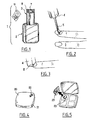
- FIG. 1 shows a packaging and application unit 1 comprising a bottle 2 containing a cosmetic composition and an applicator 3 making it possible to apply the same.
- the cosmetic composition is a nail polish comprising magnetic bodies, of the following formulation: nitrocellulose 11 N-ethyl o, p-toluenesulfonamide 5 Alkyd resin 10 isopropanol 4 Magnetic pigments * 0.5 Butyl acetate / ethyl acetate 50/50 Qs 100 * Nacres containing at least 14% of reference Fe 3 O 4 COLORONA PATINA GOLD (117288) sold by MERCK.
- the appearance of such a nail polish can be modified by applying a magnetic field before the polish has had time to dry.
- the applicator 3 comprises a gripping member 4 which also constitutes the closure member of the bottle 2 and a brush 5 for applying the composition to the nail.
- the assembly 1 comprises a magnetic device which comprises a permanent magnet 7 integrated in the gripping member 4.
- the magnet 7 is received in a housing of the gripping member and remains visible from the upper face 8 of the applicator.
- the latter may have a slightly concave shape towards the outside, in order to take into account the curvature of the nail.
- the magnetic properties of the magnet 7 can be chosen according to the pattern to be achieved on the nail, the concentration of magnetic bodies and their sensitivity.
- the magnet 7 makes it possible, for example, to generate a field of at least 500 Gauss, better still at least 2,000, or even 10,000 or 15,000 Gauss, for example between 500 and 15,000 Gauss.
- the assembly may also comprise at least one piece of information representative of a decoration that can be made on a deposit of the composition, thanks to the magnetic device 7.
- the information is on a record 11 which is for example contained in the same package as the bottle 2, this package being for example a cardboard box or a blister and not shown.
- the information may appear on a label stuck on the bottle or the applicator 3.
- the information 11 may comprise the representation of a decoration that can be obtained on the composition with the magnetic device.
- This representation is for example printed, but it can also be done differently, in particular by exposing to a magnetic field a layer of the cosmetic composition, deposited for example on the top or the side of the applicator or on the bottle, in the form of a lacquering.
- thermoplastic material which is loaded with magnetic bodies and to expose them to a magnetic field, so as to obtain a result similar to that which the magnetic device 7 has on the composition contained in FIG. inside the bottle.
- Set 1 can be used as follows.
- the user first applies the composition to the nail, as shown in FIG. 2, and before it dries, returns the applicator 3 to expose the composition to the magnetic field generated by the magnet 7, as illustrated. in Figure 3.
- the composition is for example exposed to a static magnetic field, by not moving the magnet 7 relative to the nail until the magnetic bodies are frozen, or dynamic, by moving the magnet 7 relative to the nail .
- a rotating magnetic field can create the illusion of a raised sphere.
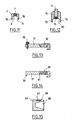
- FIG. 11 illustrates the possibility for the applicator 3 of FIG. 1 to include at least one extension 70 that can rest against a bearing surface, for example example the top of a table, to maintain the magnet 7 at a distance from the nail.
- the applicator has two lugs 70 defining between them a housing 71 that can accommodate the nail.
- FIGS. 4 and 5 show a housing 20 whose cover 21 includes information 22 representative of a decoration that can be achieved by means of a magnetic device 23 present in the housing.
- the information 22 is for example a printing or a decor made in a lacquer or in the thermoplastic material of the housing, as previously described.
- the housing 20 comprises for example a lacquering of a varnish containing magnetic bodies and which has been exposed before drying to a magnetic field as generated by the magnetic device 23.
- the housing 20 may contain several magnetic devices 23 for making different decorations and at least one composition to be applied to the skin, superficial body growths or mucous membranes.
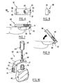
- FIGS. 6 to 8 show a device 30 making it possible to produce a decoration on the nail, by exposing a deposit of a composition comprising magnetic bodies to a magnetic field.
- the device 30 comprises a support 31 and a permanent magnet 32 which is for example fixedly mounted on the support 31 but which could, in a variant not shown, be mounted so as to be able to move relative to the support 31, for example by being driven in rotation.
- the support 31 is for example made by molding thermoplastic material and has a first stop 33 against which the distal end of the nail can come into abutment, as shown in FIG.
- the first stop 33 has a return 34 which can serve to support the inner face of the nail, which is thus positioned both horizontally and vertically relative to the support 31 in FIG.
- the support 31 comprises, on the opposite side to the first stop 33, a second stop 36 which can bear on the upper face of the finger, so as to maintain the face 38 of the permanent magnet, turned towards the nail, to a predefined distance from the nail, this distance being for example between 0.5 and 1.5 mm.
- the second stop 36 advantageously has, as well as the return 34 of the first stop 33, a slightly curved shape, adapted to the curvature of the finger, as can be seen in FIG.
- the user can first position the nail on the first stop 33 while the support 31 makes a relatively large angle with the nail, as shown in Figure 9, so that the composition which has been deposited on the nail is not strongly exposed to the magnetic field.
- the user can rotate the support relative to the nail around a hinge axis which substantially corresponds to the fulcrum of the nail against the first stop 33 until the second stop 36 comes touch of the finger.
- the user can hold the support 31 in the position of Figure 7 the time required for drying the composition.
- the magnetic bodies are fixed in the orientation that the magnet has given them.
- the abutment 36 comprises in this example a screw engaged in the support 31.
- FIG. 10 shows a packaging and application unit 40 comprising a bottle 42, an applicator 43 and a magnetic device 44.
- the bottle 42 contains a cosmetic composition comprising magnetic bodies.
- the applicator 43 is for example conventional and comprises an applicator element 60 such as a brush, mounted at the end of a rod 45 connected to a gripping member 46 which also constitutes a closure member of the bottle 42 .
- the magnetic device 44 comprises a support 47 provided with an opening 48 making it possible to engage it on the neck 49 of the bottle 42.
- the support 47 has a lateral extension 50 which can be positioned on the side of the bottle 42 and in the thickness thereof when the neck is engaged in the opening 48 and the support 47 held against the bottle 42 by the body closing 43.
- the lateral extension 50 of the support advantageously comprises a first abutment 51 similar to the first abutment 33 of the embodiment previously described, making it possible to position the nail relative to the support 47, and a permanent magnet 52 positioned relative to the first stop 51 so as to be able to come a short distance from the composition to be exposed to the magnetic field.
- the support 47 can be left in place on the bottle 42 for use.
- the pivoting of the nail relative to the support 47 can be carried out until the finger comes into contact with a second stop 54 formed by the outer surface of the support 47.
- Figure 12 shows a magnetic device in which a magnet 75 is mounted on a support 76 with a possibility of height adjustment.
- the magnet 75 is for example integral with a screw 77 to change the distance to the nail. The user can thus adjust the distance depending for example on the size of the finger or the nature of the composition deposited on the nail.
- tabs 79 are provided to define a housing 80 for the finger.
- the magnet may be a monolithic magnet or, as illustrated in FIG. 14, comprise magnetic particles 81 dispersed in a matrix, for example ferrites.
- These particles are for example incorporated into the material of the support and oriented under the action of a magnetic field while the material of the support is still fluid, so that the effects of the individual fields of the particles can accumulate.
- the support material is for example a thermoplastic material, the magnetic particles being oriented during molding before the thermoplastic material freezes.
- FIG. 15 represents an alternative embodiment in which the magnetic device comprises a nonmagnetic support 85, for example made of thermoplastic material or aluminum, provided with a housing 86 for receiving the end of the finger.
- a nonmagnetic support 85 for example made of thermoplastic material or aluminum
- a magnet 87 is mounted in a housing 88 of the support so as to exert a field on the magnetic composition deposited on the nail.
- the support has for example externally a parallelepipedal general shape.
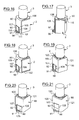
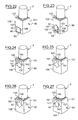
- the application conditioning device shown in FIG. 16 comprises a support 90 which is arranged to be fixed on the neck of a bottle 2, like the support 47 of the example of FIG.
- the bottle 2 has a body having a polygonal cross section, in this case square or rectangular, with substantially flat major faces.
- the support 90 comprises a frontal upright 105 which bears on one of these main faces. This frontal amount 105 is extended superiorly by an upper wall 106 provided with an opening through which the neck of the bottle 2.
- the support 90 comprises a housing housing a permanent magnet 92, which has a generally parallelepipedal shape, with vertical sides.
- the housing of the support 90 has two opposite ribs 107 and 108 each provided with a return to the inside.
- the ribs 107 and 108 may be arranged to form a slideway for engaging the magnet 92 in the housing by a sliding movement, for example from the bottom and the back of the support.
- the support 90 comprises below, under the magnet, a lug 96 which defines a first stop for the positioning of the nail relative to the magnet 92.
- This lug 96 may comprise, as illustrated, a return 91 upwards, allowing support of the inner face of the nail.
- This return 91 advantageously has a surface 110 directed towards the housing which is convex towards it.
- the upper face 111 of the lug 96 may have a concave recess upwards, in order to substantially match the shape of the edge of the nail.
- the magnet 92 can be fixed on the support in various ways, for example by snap-fastening thanks to suitable reliefs of the support and / or by gluing.
- the support 90 can be easily removed from the receptacle 2 after removal of the applicator 3.
- the lower edge 112 may be at the bottom of the bottle 2, or slightly above.
- the support 90 of the example of FIG. 17 differs from that represented in FIG. 16 by the additional presence of a return 115 extending downwardly the upper wall 106 and bearing on the main face of the bottle 2 opposite to that on which the frontal amount 105 bears. This makes it possible to immobilize the support 90 more securely in rotation relative to the bottle 2.
- the return 115 to the rear has, in the example considered, a height between one-tenth and one-third of the height of the main faces of the bottle 2, but in a variant not shown, the return 115 could extend for example to the bottom of the bottle 2.
- the support 90 comprises two lateral wings 120 and 121 which are connected to the front wall 105 and each extend over substantially the entire height of the body of the bottle 2.
- the magnet 92 is for example retained in the same manner on the support as in the example of Figure 16, the pin 96 having for example an identical shape.
- the support 90 has a general jumper shape in FIG. 18 and is for example detained by snapping onto the bottle 2. In a variant, it can be retained by gluing or otherwise, depending for example on the material constituting the bottle 2 .
- FIG. 18 differs from the example of FIG. 16 in that the frontal upright 105 is extended inferiorly by a lower wall 122 which extends under the bottle 2 and which constitutes the base of the device.
- the lug 96 is not limited to a particular shape and by way of example that shown in Figure 20 has a front edge 125 which is rounded, convex outwardly.
- the magnet 92 is for example fixed on the support 90 by being introduced from the front and from above, being for example maintained by clamping between the ribs 107 and 108.
- the magnet 92 is for example simply glued on the frontal amount 105 and the ribs 107 and 108 for example to facilitate its positioning before bonding.
- the support 90 may comprise one or more reliefs facilitating bonding, for example by forming glue traps.
- the lug has a front edge which has a concave recess forward, which can allow the positioning of the finger or the fingernail.
- the magnet 92 is for example glued on the support as in Figure 21, but may alternatively be fixed otherwise, for example by snapping or snapping and gluing.
- the magnet 92 is oriented on the support so as to have a diamond-shaped front face with a point 130 downwards.
- the magnet 92 rests on two sides 131 and 132 on the top of the ribs 108 and 107, being for example glued on the support 90.
- the lug 96 has in the example of Figure 22 a recess 93 concave forward, to position the finger or the fingernail.
- the user can in particular position the cuticle adjacent to the lunula in the recess 93 in order to obtain, thanks to the gradient of the magnetic field lines created by the magnet, a makeup of the "French manicure” type, with a gradient on the nail.
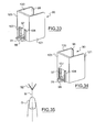
- the nail may be advantageous to subject the nail to the magnetic field generated by a portion of a magnet having a width which varies as one moves along a median plane M of the nail, such as illustrated in Figure 35, the magnet can be superimposed or not at least partially to the nail.
- the magnet may for example have a wedge shape with sides that converge towards the lunula, the polar faces of the magnet being for example oriented substantially perpendicular to the median plane M of the nail.
- the magnet 92 also has an upwardly directed tip and the support 90 has a recess 140 in the upper portion of the front post 105, to position the finger or the fingernail.
- the magnet 92 may be in the upper part of the support 90 because this may allow, compared to the example of FIG. 23, to avoid having to lift the bottle to position the nail or the finger on the support.
- the magnet 92 can be fixed in a housing delimited by an excess thickness of the frontal upright 105, the magnet 92 coming for example to bear by its upper sides 141 and 142 against a recess of the frontal upright 105.
- FIGS. 25, 26, 27 and 28 differ from that of FIG. 24 in the appearance of the frontal upright 105.
- a slight concavity 150 is formed between two thicker sidebands 151, which may facilitate visual identification for the user of where to put the fingernail.
- the strips 151 have beveled ends which are in line with the sides 141 and 142 of the magnet 92.
- the strips 151 extend over substantially the entire height of the support 90.
- the frontal upright 105 has a central rib 160 at the top and the magnet 92 comes from its sides 141 and 142 resting against a fork formed at the lower end of the rib 160. last has a recess 95 in the upper part, slightly concave forward and which allows to position the nail.
- the lateral wings 120 and 121 may have at their end a return towards the other wing to allow the maintenance of the support 90 on the bottle.
- the supports shown in FIGS. 31 to 34 comprise such a return, in the form of a rim 98 parallel to the front upright.
- the return is in the form of a chamfered rib.
- the wings may comprise, as illustrated in Figure 32, at least one relief such as a boss 99, allowing a snap of the support on the bottle 2 at the end of a sliding movement along the longitudinal axis of the bottle 2.
- the lug 96 when present, may extend over the entire width of the frontal upright 105 as illustrated in FIG. 31. In this figure, it is possible to discern returns 165, formed at the front end of the ribs 107 and 108, for the maintenance of the magnet 92, not shown in this figure. It is also possible to discern reliefs 70 such as bosses, made on the opposite faces of the ribs, for example to frictionally retain the magnet in the corresponding housing 97 of the support.
- the ribs may comprise recessed reliefs to form glue traps.
- the magnet is for example placed in the housing 97 formed between the ribs 107 and 108, being introduced from the front and over.
- the housing 97 opens out lower on the support and the magnet can be introduced through the corresponding opening 182.
- the lug 96 has a front edge that is substantially flat and parallel to the front upright 105.
- the lug 96 has a width less than the distance between the ribs 107 and 108.
- the upper edge of the support can be chamfered, in particular on the side of the inner face of the frontal amount 105 or in the upper corner of the wings 120 and 121, to facilitate the introduction of the bottle, improve the aesthetics and reduce the vulnerability to shock support.
- the support 90 may comprise, in any of the examples of FIGS. 16 to 34, information representative of a pattern that can be produced, for example in the form of a decoration made with the composition or reproduced on a label stuck on the support or by an impression of the support.
- the support 90 may have a different shape, adapted for example to a bottle 2 whose body is cylindrical or frustoconical.
- the support 90 can be made, if necessary, with a hinge and a movable portion pivotable between a configuration for placing the support on the bottle and a holding position of the bottle on the support.
- the support can be provided with several magnets, the latter having, for example, different magnetic properties in order to create different decorations.
- the support can be made with an adjustable part to adapt it to several sizes of bottles and / or several sizes of fingers or nails and / or several types of decorations to achieve.
- the device comprises an applicator 3 having a rod provided at one end with an applicator element such as a brush and at another end of a gripping member which is also the closure cap of the bottle 2.
- the bottle has no applicator 3, the application of the product being effected for example other than by means of a brush introduced into the container, for example directly using a dispensing orifice of the bottle.
- Permanent magnets can be replaced by at least one electromagnet.
Landscapes
- Cosmetics (AREA)
- Magnetic Treatment Devices (AREA)
- Coating Apparatus (AREA)
- Burglar Alarm Systems (AREA)
- Manufacturing Of Magnetic Record Carriers (AREA)
Abstract
- un support comportant au moins une première butée (33) et/ou un renfoncement (140) contre lequel ou laquelle l'ongle et/ou le doigt peut venir en appui, ce support étant agencé pour se fixer sur un flacon contenant la composition,
- au moins un aimant permanent (32) ou électroaimant positionné sur le support relativement à la première butée (33) et/ou le renfoncement (140) de manière à exposer le dépôt de composition formé sur l'ongle à un champ magnétique lorsque l'ongle et/ou le doigt est en appui contre la butée et/ou le renfoncement (140).
Description
- La présente invention concerne les ensembles de conditionnement et d'application d'une composition cosmétique et plus particulièrement ceux destinés à l'application d'une composition comportant des corps présentant une susceptibilité magnétique non nulle.
- Selon l'un de ses aspects, parmi d'autres, l'invention a pour objet un ensemble de conditionnement et d'application comportant :
- un contenant renfermant une composition à appliquer, cette composition comportant des corps magnétiques, c'est-à-dire présentant une susceptibilité magnétique non nulle,
- un dispositif magnétique permettant de réaliser un décor sur au moins une couche de composition appliquée sur des matières kératiniques, par exemple la peau, les muqueuses ou les phanères, et
- au moins une information représentative d'un décor pouvant être réalisé sur la composition grâce au dispositif magnétique. Cette information peut être une représentation dudit décor.
- L'invention permet à l'utilisateur de créer de nouveaux effets de maquillage, en modifiant l'orientation des corps magnétiques et/ou en les déplaçant.
- L'information peut être située sur le contenant et/ou sur le dispositif magnétique.
- L'ensemble peut comporter un applicateur et l'information peut être située sur l'applicateur, notamment sur un organe de préhension.
- Dans un exemple de mise en oeuvre de l'invention, l'information comporte un décor formé au moins partiellement par l'orientation de corps magnétiques sous l'effet d'un champ magnétique. L'ensemble comporte par exemple un dépôt de composition sous forme d'un laquage ayant été exposé à un champ magnétique. En variante, l'ensemble comporte une matière thermoplastique incluant des corps magnétiques dont l'orientation a été modifiée par exposition à un champ magnétique, de façon à créer le décor.
- L'information peut encore être formée au moins partiellement par une impression.
- Le contenant peut comporter un boîtier ou un flacon, l'information étant par exemple située sur un organe de fermeture du contenant.
- L'information peut encore être contenue dans un emballage du contenant et/ou de l'applicateur, étant par exemple imprimée sur une notice figurant dans cet emballage.
- La composition peut être un vernis à ongles ou tout autre produit à appliquer sur la peau, les phanères ou les muqueuses.
- L'applicateur peut comporter un organe d'application relié à un organe de fermeture du récipient, et le dispositif magnétique peut être incorporé à l'organe de fermeture. Le dispositif magnétique comporte par exemple un aimant permanent fixé dans un logement correspondant de l'organe de fermeture, l'aimant étant par exemple collé dans ce logement. Le dispositif magnétique peut encore comporter des particules aimantées orientées, présentes par exemple au sein d'une matière thermoplastique ou d'une résine.
- Le dispositif magnétique peut comporter un électroaimant.
- L'aimant ou électroaimant présente par exemple une face apparente située sur le dessus de l'organe de fermeture.
- Un tel ensemble s'avère pratique à utiliser, et notamment permet à l'utilisateur d'exposer rapidement un dépôt de composition à un champ magnétique avant le séchage complet de la composition.
- Le dispositif magnétique peut comporter au moins une surface destinée à reposer contre un appui fixe afin de maintenir l'aimant ou électroaimant à une distance prédéfinie de la région sur laquelle la composition est appliquée. Le dispositif magnétique comporte par exemple deux pattes pouvant reposer contre une surface plane horizontale lors de l'utilisation et permettant à l'utilisateur de glisser son doigt entre elles pour l'exposition au champ magnétique.
- Le dispositif magnétique peut comporter des moyens de réglage permettant à l'utilisateur de régler par exemple la distance ou l'orientation de l'aimant ou électroaimant relativement à la région revêtue de la composition magnétique.
- Le dispositif magnétique peut comporter un logement permettant d'introduire l'extrémité du doigt.
- Selon un autre de ses aspects, indépendamment ou en combinaison avec ce qui précède, l'invention a encore pour objet un dispositif de conditionnement et d'application comportant :
- un flacon contenant une composition à appliquer sur les ongles,
- un support fixé sur le flacon, ce support portant un aimant et présentant une surface d'appui pour le doigt et/ou l'ongle, notamment un renfoncement ou une butée, permettant de former un décor sur l'ongle en exposant une couche de la composition déposée sur l'ongle au champ magnétique de l'aimant,
- un applicateur éventuel, agencé pour se fixer sur le flacon, le support n'étant pas solidaire de l'applicateur lors de l'utilisation.
- L'invention a encore pour objet, un dispositif magnétique permettant de réaliser un décor sur un ongle sur lequel un dépôt d'une composition comportant des corps magnétiques a été effectué, ce dispositif comportant :
- un support comportant au moins une première butée et/ou un renfoncement contre lequel ou laquelle l'ongle et/ou le doigt peut venir en appui, ce support étant agencé pour se fixer sur un flacon contenant la composition,
- au moins un aimant permanent ou électroaimant positionné sur le support relativement à la première butée et/ou au renfoncement de manière à exposer le dépôt de composition formé sur l'ongle à un champ magnétique lorsque l'ongle et/ou le doigt est en appui contre la butée et/ou le renfoncement.
- L'invention a encore pour objet, un ensemble comportant un flacon contenant une composition à appliquer sur les ongles et un dispositif tel que défini plus haut, fixé sur ce flacon.
- Le support peut comporter un ergot définissant une première butée pour l'ongle.
- Le flacon peut présenter un corps ayant une section transversale généralement carrée ou rectangulaire. Le corps du flacon peut être en verre ou en un autre matériau, notamment une matière thermoplastique.
- Le support peut comporter, par exemple, deux ailes réunies par un montant frontal, le flacon étant engagé entre ces ailes, la surface d'appui précitée pouvant être définie par le montant frontal.
- L'une au moins des ailes peut comporter un retour arrière, de retenue du flacon entre les ailes.
- L'une au moins des ailes peut comporter un relief permettant d'immobiliser par encliquetage le flacon, par exemple après introduction de celui-ci par un mouvement de coulissement entre les ailes.
- Dans un exemple de réalisation, le support comporte une ouverture permettant sa mise en place sur un col du flacon. Cette ouverture peut être réalisée dans une paroi supérieure se raccordant à l'avant à un montant frontal du support. Cette paroi supérieure peut se raccorder à l'arrière à un retour dirigé vers le bas, agencé pour s'appliquer sur une face arrière du flacon.
- Le support peut comporter un montant frontal se raccordant inférieurement à une paroi inférieure agencée pour se positionner sous le flacon.
- Dans une variante de réalisation, le support comporte une paroi inférieure agencée pour se fixer sur le fond du flacon, par exemple par collage.
- Indépendamment de sa forme et de la manière dont il est fixé sur le flacon, le support peut comporter un logement et l'aimant peut être engagé au moins partiellement dans ce logement, étant par exemple fixé dans celui-ci par encliquetage et/ou collage.
- Dans un exemple de mise en oeuvre de l'invention, le logement comporte deux nervures opposées, de retenue de l'aimant.
- L'aimant est par exemple engagé dans le logement par un mouvement de coulissement entre ces nervures.
- Le logement peut être agencé pour permettre une fixation par encliquetage de l'aimant et l'une au moins des nervures précitées peut comporter par exemple un bossage qui est franchi par l'aimant lors de sa mise en place.
- Le logement peut comporter au moins un relief facilitant le collage de l'aimant dans le logement, en accueillant la colle.
- Le logement peut déboucher inférieurement et/ou entre les ailes éventuelles du support, afin par exemple de permettre une mise en place de l'aimant par-dessous et/ou par l'arrière.
- Le logement peut être délimité inférieurement par un ergot qui peut définir une butée pour l'ongle.
- Cet ergot peut présenter un bord avant arrondi, convexe vers l'avant ou en variante un bord avant concave vers l'avant. Un bord concave peut par exemple permettre d'appliquer contre celui-ci la cuticule de l'ongle à exposer au champ magnétique. L'ergot peut encore comporter un bord avant plat ou ayant une forme autre.
- L'aimant peut présenter diverses formes, notamment une forme parallélépipédique.
- L'aimant peut être disposé sur le support avec au moins un côté vertical ou en variante l'aimant peut présenter une face avant ayant une forme de losange, ce qui peut permettre de soumettre la couche de composition à un gradient de champ magnétique facilitant la réalisation d'un maquillage de type « French manucure ».
- Le support peut comporter un montant frontal présentant supérieurement un renfoncement épousant sensiblement la forme du doigt ou de l'ongle, ce qui peut être utile notamment lorsque l'aimant présente une face avant en forme de losange, pour positionner correctement l'ongle.
- L'aimant peut venir, notamment lorsqu'il présente une forme de losange, en appui par deux côtés seulement contre un bord du logement.
- L'aimant peut être situé dans la moitié inférieure du support ou en variante dans sa moitié supérieure ou ailleurs encore.
- Lorsque l'aimant est situé dans la partie inférieure du support, celui-ci peut s'utiliser par exemple avec l'ongle dirigé vers le bas, le bord de l'ongle prenant par exemple appui contre l'ergot précité, lequel peut être muni d'un retour permettant également un appui de la face intérieure de l'ongle.
- Le support peut comporter un montant frontal présentant supérieurement un renfoncement épousant sensiblement la forme du doigt ou de l'ongle.
- L'aimant peut venir en appui par deux côtés seulement contre un bord d'un logement correspondant du support.
- Le support peut être fixé de façon amovible sur le flacon, afin de permettre par exemple à l'utilisateur de remplacer le flacon lorsque la composition est épuisée. En variante, le support peut être fixé de façon non amovible sur le flacon.
- Selon un autre de ses aspects, indépendamment ou en combinaison avec ce qui précède, l'invention a encore pour objet un dispositif magnétique comportant :
- un support comportant au moins une première butée contre laquelle l'ongle et/ou le doigt peut venir en appui,
- au moins un aimant permanent ou électroaimant positionné sur le support relativement à la première butée de manière à pouvoir exposer un dépôt de composition formé sur l'ongle à un champ magnétique lorsque l'ongle et/ou le doigt est en appui contre la butée. L'aimant ou électroaimant est par exemple rapproché du dépôt alors que le doigt et/ou l'ongle est en appui contre la première butée.
- Un tel dispositif permet de réaliser un motif sur l'ongle en réduisant notamment le risque de contact accidentel du vernis avec le dispositif magnétique et facilite la reproductibilité de la réalisation d'un décor sur l'ongle.
- La première butée peut être réglable, le cas échéant, de même que la position de l'aimant ou électroaimant relativement au support.
- La première butée peut comporter un retour permettant un appui de la face intérieure de l'ongle. Ce retour peut permettre à l'utilisateur de faire pivoter plus facilement le support relativement à l'ongle.
- Le support comporte avantageusement une deuxième butée agencée pour venir en appui sur le dessus du doigt lorsque l'ongle est introduit dans le champ magnétique de l'aimant. Cette deuxième butée peut être réglable.
- Les première et deuxième butées présentent avantageusement des formes incurvées, adaptées à la courbure de l'ongle et/ou du doigt.
- Le support peut être agencé pour se fixer sur un flacon en l'absence d'utilisation.
- Le support comporte par exemple une ouverture à engager sur le col du flacon.
- L'invention a encore pour objet, selon un autre de ses aspects, un procédé de formation d'un décor sur l'ongle, comportant les étapes suivantes :
- déposer sur l'ongle une couche d'une composition contenant des corps magnétiques,
- soumettre le dépôt à un champ magnétique au moyen d'un dispositif magnétique amené par un mouvement prédéfini dans le voisinage du dépôt, notamment un mouvement de pivotement.
- Le pivotement peut notamment s'effectuer autour d'un appui de l'ongle et/ou du doigt contre un support du dispositif magnétique. Ce dernier est avantageusement tel que défini ci-dessus, comportant au moins une première butée pour l'ongle et/ou le doigt.
- L'invention a encore pour objet, selon un autre de ses aspects, indépendamment ou en combinaison avec ce qui précède, un procédé de maquillage de l'ongle comportant les étapes suivantes :
- déposer sur l'ongle une couche d'une composition cosmétique contenant des corps magnétiques,
- soumettre le dépôt à un champ magnétique présentant un gradient de champ magnétique, de telle manière à créer une modification de l'aspect de la composition avec une variation progressive de l'aspect vers le bord libre de l'ongle.
- Un tel procédé peut notamment permettre de réaliser un maquillage de type « French manucure ».
- Le champ magnétique peut être exercé par exemple au moyen d'un aimant ayant une portion en forme de coin, convergeant dans une direction sensiblement parallèle à un plan médian de l'ongle. Un aimant ayant une forme de losange lorsque le flacon est vertical peut par exemple être utilisé, l'ongle étant orienté alors verticalement, par exemple.
- L'invention a encore pour objet un dispositif magnétique permettant de réaliser un décor sur un ongle sur lequel un dépôt d'une composition comportant des corps magnétiques a été effectué, comportant un support et au moins un aimant ou électroaimant porté par le support, ce dernier présentant un logement pour recevoir l'ongle et étant agencé pour maintenir l'aimant ou électroaimant à une distance prédéfinie de l'ongle présent dans le logement.
- L'invention a encore pour objet, selon un autre de ses aspects, indépendamment ou en combinaison avec ce qui précède, un ensemble de conditionnement et d'application comportant :
- un récipient contenant une composition cosmétique à appliquer, ce récipient présentant un col,
- un dispositif magnétique comportant un support pourvu d'une ouverture à engager sur le col et au moins un aimant permanent.
- Un tel support assure le maintien du dispositif magnétique sur le récipient en l'absence d'utilisation.
- L'ensemble de conditionnement et d'application peut comporter un organe de fermeture du récipient, agencé pour maintenir le support sur le col lorsqu'il ferme le récipient.
- L'invention a encore pour objet un procédé de fabrication d'un dispositif magnétique, destiné par exemple à la mise en oeuvre du procédé de formation d'un décor précité, comportant un support et des particules magnétiques incorporées au support, dans lequel le support est réalisé dans une matière fluide pouvant se solidifier et dans lequel avant la solidification de la matière du support les particules sont orientées sous l'action d'un champ magnétique. Les particules magnétiques, après orientation, se comportent comme un aimant permanent.
- Un tel procédé de fabrication peut faciliter la réalisation d'un dispositif magnétique ayant une géométrie de champ magnétique prédéfinie, convenant au décor à réaliser.
- Le support peut faire partie d'un applicateur de produit cosmétique.
- Par « corps magnétiques », on désigne des corps présentant une susceptibilité magnétique non nulle, c'est-à-dire sensibles à l'action d'un champ magnétique et tendant par exemple à s'aligner sur les lignes de champ. L'expression « corps magnétique » englobe ainsi les corps magnétisables.
- De préférence, les corps magnétiques utilisés ne présentent pas d'aimantation rémanente en l'absence de champ magnétique.
- Les corps magnétiques peuvent comporter tout matériau magnétique présentant une sensibilité aux lignes d'un champ magnétique, que ce champ soit produit par un aimant permanent ou issu d'une induction, ce matériau étant par exemple choisi parmi le nickel, le cobalt, le fer, leurs alliages et oxydes, notamment Fe3O4, et aussi le gadolinium, le terbium, le dysprosium, l'erbium, leurs alliages et oxydes. Le matériau magnétique peut comporter du fer métal, notamment du fer doux, éventuellement enrobé.
- Les corps magnétiques peuvent présenter ou non une structure multicouche, comportant au moins une couche d'un matériau magnétique, tel que par exemple le fer, le nickel, le cobalt, leurs alliages et oxydes, notamment Fe3O4.
- Les corps magnétiques sont de préférence asphériques, présentant par exemple une forme allongée. Ainsi, lorsque ces corps sont soumis au champ magnétique, ils tendent à s'orienter avec leur axe longitudinal dans l'alignement des lignes de champ, et subissent un changement d'orientation qui se traduit par un changement d'aspect de la composition.
- Lorsque les corps magnétiques sont sensiblement sphériques, de préférence leur aspect est inhomogène, de manière à ce qu'un changement d'orientation induise un changement d'aspect.
- La quantité de corps magnétiques est suffisante pour que l'aspect de la composition puisse dépendre de leur orientation et/ou de leur emplacement.
- La concentration en corps magnétiques est par exemple comprise entre environ 0,05 et environ 97 % en masse, notamment entre environ 0,1 et environ 95 % en masse, mieux entre environ 0,1 et environ 90 % en masse, par exemple de l'ordre de 3 % en masse. La dimension des corps magnétiques est par exemple comprise entre 1 nm et 700 µm, mieux entre 1 µm et 500 µm, mieux encore entre 10 µm et 150 µm. Par « dimension », on désigne la dimension donnée par la distribution granulométrique statistique à la moitié de la population, dite D50.
- Les corps magnétiques de la composition peuvent comporter des pigments magnétiques. Des pigments convenant tout particulièrement sont les nacres comportant de l'oxyde de fer Fe3O4. Des pigments présentant des propriétés magnétiques sont par exemple ceux commercialisés sous les dénominations commerciales COLORONA BLACKSTAR BLUE, COLORONA BLACKSTAR GREEN, COLORONA BLACKSTAR GOLD, COLORONA BLACKSTAR RED, CLOISONNE NU ANTIQUE SUPER GREEN, MICRONA MATTE BLACK (17437), MICA BLACK (17260), COLORONA PATINA SILVER (17289) et COLORONA PATINA GOLD (117288) par la société MERCK ou bien encore FLAMENCO TWILIGHT RED, FLAMENCO TWILIGHT GREEN, FLAMENCO TWILIGHT GOLD, FLAMENCO TWILIGHT BLUE, TIMICA NU ANTIQUE SILVER 110 AB, TIMICA NU ANTIQUE GOLD 212 GB, TIMICA NU-ANTIQUE COPPER 340 AB, TIMICA NU ANTIQUE BRONZE 240 AB, CLOISONNE NU ANTIQUE GREEN 828 CB, CLOISONNE NU ANTIQUE BLUE 626 CB, GEMTONE MOONSTONE G 004, CLOISONNE NU ANTIQUE RED 424 CB, CHROMA-LITE BLACK (4498), CLOISONNE NU ANTIQUE ROUGE FLAMBE (code 440 XB), CLOISONNE NU ANTIQUE BRONZE (240 XB), CLOISONNE NU ANTIQUE GOLD (222 CB) et CLOISONNE NU ANTIQUE COPPER (340 XB) par la société ENGELHARD.
- On peut encore citer les particules d'oxyde de fer noir commercialisées par la société BASF ou les particules à base de fer doux.
- Les corps magnétiques peuvent être des fibres.
- Le terme « fibres » désigne des corps généralement allongés, présentant par exemple un facteur de forme allant de 3,5 à 2 500 ou de 5 à 500, par exemple de 5 à 150. Le facteur de forme est défini par le rapport L/D, où L est la longueur de la fibre et D le diamètre du cercle dans lequel s'inscrit la plus grande section transversale de la fibre.
- La section transversale des fibres peut s'inscrire par exemple dans un cercle de diamètre allant de 2 nm à 500 µm, par exemple allant de 100 nm à 100 µm, voire de 1 µm à 50 µm.
- Les fibres peuvent présenter par exemple une longueur allant de 1 µm à 10 mm, par exemple de 0,1 mm à 5 mm, voire de 0,3 mm à 3,5 mm.
- Les fibres peuvent présenter une masse allant par exemple de 0,15 à 30 deniers (masse en gramme pour 9 km de fil), par exemple de 0,18 à 18 deniers.
- La forme en section transversale des fibres peut être quelconque, par exemple circulaire ou polygonale, notamment carrée, hexagonale ou octogonale.
- La composition peut comporter des fibres pleines ou creuses, indépendantes ou liées entre elles, par exemple tressées.
- La composition peut comporter des fibres ayant des extrémités épointées et/ou arrondies, par exemple par polissage.
- Les fibres peuvent ne pas voir leur forme sensiblement modifiée lorsqu'elles sont introduites dans la composition, étant par exemple initialement rectilignes et suffisamment rigides pour conserver leur forme. En variante, les fibres peuvent présenter une souplesse leur permettant de se déformer sensiblement au sein de la composition.
- Les fibres peuvent comporter une teneur non nulle, pouvant aller jusqu'à 100 %, d'un matériau magnétique à base de fer, de zinc, de nickel, de cobalt ou de manganèse et leurs alliages et oxydes, notamment Fe3O4, les terres rares, le sulfate de baryum, les alliages de fer silicium, éventuellement chargés en molybdène, Cu2MnAl, MnBi, ou un mélange de ceux-ci, cette liste n'étant pas limitative.
- Lorsque la composition comporte des fibres contenant des particules magnétiques, ces dernières peuvent être présentes par exemple au moins à la surface de la fibre, voire à la surface des fibres uniquement, à l'intérieur de la fibre uniquement ou encore être dispersées au sein de la fibre de manière sensiblement homogène.
- Les fibres peuvent comporter par exemple un coeur non magnétique avec une pluralité de particules magnétiques à sa surface.
- Les fibres peuvent encore comporter une matrice synthétique contenant une pluralité de grains magnétiques dispersés en son sein.
- Le cas échéant, une matière synthétique chargée de particules magnétiques peut elle-même être enrobée par une écorce non magnétique. Une telle écorce constitue par exemple une barrière isolant le ou les matériaux magnétiques du milieu ambiant et/ou peut amener de la couleur. Les fibres peuvent comporter un coeur magnétique monolithique et être enrobées par une écorce non magnétique, ou cela peut être l'inverse.
- La composition peut comporter des fibres réalisées par extrusion ou co-extrusion d'une ou plusieurs matières polymériques, notamment thermoplastiques et/ou élastomères. L'une des matières extrudées peut contenir une charge de particules magnétiques dispersées.
- Les fibres peuvent comporter une matière synthétique choisie parmi les polyamides, PET, acétates, polyoléfines, notamment PE ou PP, PVC, polyester bloc amide, Rilsan® plastifié, élastomères, notamment élastomères de polyester, élastomères de PE, élastomères de silicone, élastomères de nitrile ou un mélange de ces matériaux, cette liste n'étant pas limitative.
- La composition peut contenir des fibres composites comportant un coeur magnétique enrobé au moins partiellement par au moins un matériau amagnétique, synthétique ou naturel. L'enrobage du coeur magnétique peut se faire par exemple par co-extrusion, autour du coeur, d'une écorce en un matériau non magnétique.
- L'enrobage du coeur peut encore s'effectuer autrement, par exemple par polymérisation in situ.
- Le coeur peut être monolithique ou comporter une charge de grains magnétiques dispersés dans une matrice.
- La composition peut encore contenir des fibres composites obtenues par enrobage par une matière synthétique, chargée de particules magnétiques, d'un coeur amagnétique, synthétique ou naturel, le coeur étant composé par exemple d'une fibre de bois, de rayonne, de polyamide, d'une matière végétale, de polyoléfine, notamment de polyéthylène, de Nylon®, de polyimide-amide, d'aramide, cette liste n'étant pas limitative.
- La composition peut encore comporter des particules composites magnétiques, notamment un latex magnétique.
- Une particule composite magnétique est un matériau composite constitué d'une matrice organique ou minérale et de grains magnétiques. Les particules composites magnétiques peuvent ainsi comporter à leur surface et/ou en leur sein des grains d'un matériau magnétique. Les particules composites peuvent être constituées d'un coeur magnétique enrobé d'une matrice organique ou minérale, ou inversement.
- Les particules composites magnétiques comportent par exemple l'un des matériaux magnétiques précités.
- La dimension des particules composites magnétiques est par exemple comprise entre 1 nm et 1 mm, mieux entre 100 nm et 500 µm, mieux encore entre 500 nm et 100 µm. Par « dimension », on désigne la dimension donnée par la distribution granulométrique statistique à la moitié de la population, dite D50.
- La thèse de C. GOUBAULT, 23 Mars 2004, incorporée ici par référence, rappelle au chapitre 1 l'état de l'art en matière de particules composites magnétiques, et dresse une liste de procédés de préparation pouvant être utilisés pour préparer des particules composites magnétiques, à savoir une synthèse séparée des grains magnétiques et de la matrice, une synthèse des grains magnétiques au contact de la matrice ou une synthèse de la matrice en présence des grains magnétiques.
- La société KISKER commercialise des particules magnétiques composites à matrice minérale, composée de silice. Les sociétés DYNAL, SERADYN, ESTAPOR et ADEMTECH proposent des particules magnétiques composites à matrice organique, susceptibles également d'être utilisées dans l'invention.
- Plus particulièrement, la société ESTAPOR commercialise sous la référence M1-070/60 des latex magnétiques constitués de grains de ferrite uniformément répartis dans une matrice polystyrène, ce latex comportant 65 % d'oxyde de fer, le diamètre moyen des particules de polystyrène étant de 890 nm et la teneur massique en matières sèches de 10 %.
- La composition peut comporter un ferrofluide, c'est-à-dire une suspension colloïdale stable de particules magnétiques, notamment de nanoparticules magnétiques.
- Les particules, d'une taille par exemple de l'ordre de quelques dizaines de nanomètres, sont dispersées dans un solvant (eau, huile, solvant organique), soit à l'aide d'un tensioactif ou d'un agent dispersant, soit par des interactions électrostatiques.
- Les ferrofluides sont par exemple préparés par broyage de ferrites ou autres particules magnétiques jusqu'à l'obtention de nanoparticules qui sont ensuite dispersées dans un fluide contenant un surfactant, lequel s'adsorbe sur les particules et les stabilise, ou par précipitation en milieu basique d'une solution d'ions métalliques.
- Chaque particule du ferrofluide présente un moment magnétique déterminé par la taille de la particule et par la nature du matériau magnétique.
- Sous l'action d'un champ magnétique, les moments magnétiques des particules tendent à s'aligner suivant les lignes de champ, avec apparition d'une aimantation non nulle dans le liquide. Si le champ est annulé, il n'y a pas d'hystérésis et l'aimantation s'annule.
- Au-delà d'une valeur seuil de champ, on peut également provoquer des changements macroscopiques dans le liquide, par exemple l'apparition de pics ou une modification des propriétés rhéologiques.
- La dénomination « ferrofluide » englobe également une émulsion de gouttelettes de ferrofluide dans un solvant. Chaque goutte contient alors des particules magnétiques colloïdales en suspension stable. Cela permet de disposer d'un ferrofluide dans tout type de solvant. La dimension des particules magnétiques en suspension dans le ferrofluide est par exemple comprise entre 1 nm et 10 µm, mieux entre 1 nm et 1 µm, mieux encore entre 1 nm et 100 nm. Par « dimension », on désigne la dimension donnée par la distribution granulométrique statistique à la moitié de la population, dite D50.
- On peut citer notamment les ferrofluides commercialisés par la société LIQUIDS RESEARCH LTD sous les références :
- WHKS1S9 (A, B ou C), qui est un ferrofluide à base aqueuse comportant de la magnétite (Fe3O4), ayant des particules de 10 nm de diamètre,
- WHJS1 (A, B ou C), qui est un ferrofluide à base d'iso-paraffine et de particules de magnétite (Fe3O4) de 10 nm de diamètre,
- BKS25_dextran, qui est un ferrofluide à base aqueuse stabilisé par du dextran, comportant des particules de magnétite (Fe3O4) de 9 nm de diamètre.
- La composition peut encore comporter des chaînes de particules et/ou de fibres magnétiques.
- La composition peut ainsi comporter des agglomérats de particules ou fibres dont la plus grande dimension, par exemple la longueur, est par exemple comprise entre 1 nm et 10 mm, par exemple entre 10 nm et 5 mm, ou entre 100 nm et 1 mm, ou encore entre 0,5 µm et 3,5 mm, par exemple entre 1 µm et 150 µm. La dimension désigne celle donnée par la distribution granulométrique statistique à la moitié de la population, dite D50.
- Des chaînes de particules magnétiques peuvent être obtenues par exemple en assemblant des particules magnétiques colloïdales, comme cela est décrit dans les publications « Permanently linked monodisperse paramagnetic chains », E.M. Furst, C. Suzuki, M. Fermigier, A.P. Gast, Langmuir, 14, 7334-7336 (1998), « Suspensions de particules magnétiques », M. Fermigier, Y. Grasselli, Bulletin de la SFP (105) juillet 96, et « Flexible magnetic filaments as micromechanical sensors », C. Goubault, P. Jop, M. Fermigier, J. Baudry, E. Bertrand, J. Bibette, Phys. Rev. Lett., 91, 26, 260802-1 à 260802-4 (2003), dont les contenus sont incorporés par référence.
- Il est notamment décrit dans ces articles comment procéder pour obtenir des chaînes de particules de latex magnétiques comportant une matrice de polystyrène contenant des grains d'oxyde de fer et fonctionnalisées en surface, liées entre elles de façon permanente suite à une réaction chimique, notamment des liaisons covalentes entre les surfaces des particules adjacentes ; il est également décrit un procédé d'obtention de chaînes de gouttelettes d'émulsion de ferrofluides, liées entre elles par interactions de nature physique. La longueur ainsi que le diamètre des chaînes permanentes ainsi obtenues peuvent être contrôlés. De telles chaînes magnétiques constituent des objets magnétiques anisotropes orientables et déplaçables sous l'effet d'un champ magnétique.
- Les dimensions des chaînes magnétiques peuvent répondre aux mêmes conditions que les fibres magnétiques.
- La composition comporte un milieu physiologiquement acceptable. Par « milieu physiologiquement acceptable », on désigne un milieu non toxique et susceptible d'être appliqué sur la peau, les phanères ou les lèvres d'êtres humains. Le milieu physiologiquement acceptable est généralement adapté à la nature du support sur lequel doit être appliquée la composition ainsi qu'à la forme sous laquelle la composition est conditionnée.
- La composition peut comporter d'autres ingrédients que ceux décrits plus haut, notamment au moins un solvant, une phase grasse, un polymère filmogène et/ou un actif dermatologique ou cosmétique, notamment en fonction de la forme galénique.
- La composition peut avantageusement comporter un solvant volatil, notamment un solvant organique volatil. L'orientation des corps magnétiques peut être modifiée et/ou ces derniers déplacés avant l'évaporation du solvant.
- Les différents aspects de l'invention pourront être mieux compris à la lecture de la description détaillée qui va suivre, et à l'examen du dessin annexé, sur lequel :
- la figure 1 représente en élévation un ensemble de conditionnement et d'application selon un exemple de mise en oeuvre de l'invention,
- la figure 2 illustre l'application de la composition sur l'ongle,
- la figure 3 illustre l'exposition au champ magnétique,
- la figure 4 représente un boîtier selon un autre aspect de l'invention,
- la figure 5 représente le boîtier de la figure 4, après ouverture du couvercle,
- la figure 6 est une vue de dessous d'un dispositif magnétique permettant de réaliser un motif sur l'ongle,
- la figure 7 est une coupe longitudinale selon VII-VII de la figure 6,
- la figure 8 est une vue de côté selon VIII-VIII de la figure 6,
- la figure 9 est une vue analogue à la figure 7, avant rapprochement du dispositif magnétique,
- la figure 10 représente de manière schématique, en perspective, un ensemble de conditionnement et d'application réalisé conformément à un autre aspect de l'invention,
- la figure 11 est une coupe partielle et schématique d'une variante de réalisation,
- la figure 12 représente en coupe un dispositif magnétique conforme à une variante de mise en oeuvre de l'invention,
- les figures 13 et 14 sont des vues analogues à la figure 7 représentant des variantes de réalisation,
- la figure 15 représente en coupe un dispositif magnétique selon une autre variante de réalisation,
- les figures 16 à 30 représentent en perspective divers exemples d'ensembles de conditionnement et d'application selon des variantes de mise en oeuvre de l'invention,
- les figures 31 à 34 représentent isolément, en perspective, différents supports réalisés conformément à l'invention, et
- la figure 35 représente schématiquement, en vue de dessus, un ongle et un aimant ayant une portion en forme de coin.
- On a représenté à la figure 1 un ensemble de conditionnement et d'application 1 comportant un flacon 2 contenant une composition cosmétique et un applicateur 3 permettant d'appliquer celle-ci.
- Dans l'exemple considéré, la composition cosmétique est un vernis à ongles comportant des corps magnétiques, de formulation suivante :
Nitrocellulose 11 N-éthyl o,p-toluènesulfonamide 5 Résine alkyde 10 Isopropanol 4 Pigments magnétiques* 0,5 Acétate de butyle/acétate d'éthyle 50/50 Qsp 100 *Nacres contenant au moins 14 % de Fe3O4 de référence COLORONA PATINA GOLD (117288) commercialisées par la société MERCK. - L'aspect d'un tel vernis à ongles peut être modifié en appliquant un champ magnétique, avant que le vernis n'ait eu le temps de sécher.
- Bien entendu, l'invention n'est pas limitée à une composition particulière.
- L'applicateur 3 comporte un organe de préhension 4 qui constitue également l'organe de fermeture du flacon 2 et un pinceau 5 permettant d'appliquer la composition sur l'ongle.
- L'ensemble 1 comporte un dispositif magnétique qui comprend un aimant permanent 7 intégré à l'organe de préhension 4.
- Dans l'exemple considéré, l'aimant 7 est reçu dans un logement de l'organe de préhension et reste apparent depuis la face supérieure 8 de l'applicateur. Cette dernière peut présenter le cas échéant une forme légèrement concave vers l'extérieur, afin de tenir compte de la courbure de l'ongle.
- Les propriétés magnétiques de l'aimant 7 peuvent être choisies en fonction du motif à réaliser sur l'ongle, de la concentration en corps magnétiques et de leur sensibilité. L'aimant 7 permet par exemple de générer un champ d'au moins 500 Gauss, mieux d'au moins 2000, voire 10000 ou 15000 Gauss, par exemple compris entre 500 et 15000 Gauss.
- L'ensemble peut comporter par ailleurs au moins une information représentative d'un décor pouvant être réalisé sur un dépôt de la composition, grâce au dispositif magnétique 7.
- Cette information peut se présenter de multiples manières.
- Dans l'exemple considéré, l'information figure sur une notice 11 qui est par exemple contenue dans le même emballage que le flacon 2, cet emballage étant par exemple une boîte cartonnée ou un blister et non représenté.
- En variante, l'information peut figurer sur une étiquette collée sur le flacon ou l'applicateur 3.
- L'information 11 peut comporter la représentation d'un décor pouvant être obtenu sur la composition avec le dispositif magnétique. Cette représentation est par exemple imprimée mais elle peut encore être réalisée autrement, notamment en exposant à un champ magnétique une couche de la composition cosmétique, déposée par exemple sur le dessus ou le côté de l'applicateur ou sur le flacon, sous forme d'un laquage.
- On peut encore utiliser pour mouler l'organe de préhension 4 une matière thermoplastique chargée de corps magnétiques et exposer ceux-ci à un champ magnétique, afin d'obtenir un résultat similaire à celui que permet le dispositif magnétique 7 sur la composition contenue à l'intérieur du flacon.
- L'ensemble 1 peut s'utiliser de la manière suivante.
- L'utilisateur commence par appliquer la composition sur l'ongle, comme illustré à la figure 2, puis avant que celle-ci ne sèche, retourne l'applicateur 3 pour exposer la composition au champ magnétique généré par l'aimant 7, comme illustré à la figure 3.
- La composition est par exemple exposée à un champ magnétique statique, en ne déplaçant pas l'aimant 7 relativement à l'ongle jusqu'à ce que les corps magnétiques soient figés, ou dynamique, en déplaçant l'aimant 7 relativement à l'ongle. Un champ magnétique rotatif peut créer par exemple l'illusion d'une sphère en relief.
- On a illustré à la figure 11 la possibilité pour l'applicateur 3 de la figure 1 de comporter au moins une extension 70 pouvant reposer contre une surface d'appui, par exemple le dessus d'une table, pour maintenir l'aimant 7 à une certaine distance de l'ongle. Dans l'exemple illustré, l'applicateur comporte deux pattes 70 définissant entre elles un logement 71 pouvant accueillir l'ongle.
- On a représenté aux figures 4 et 5 un boîtier 20 dont le couvercle 21 comporte une information 22 représentative d'un décor pouvant être réalisé grâce à un dispositif magnétique 23 présent dans le boîtier. L'information 22 est par exemple une impression ou un décor réalisé dans un laquage ou dans la matière thermoplastique du boîtier, de la manière précédemment décrite.
- Le boîtier 20 comporte par exemple un laquage d'un vernis contenant des corps magnétiques et qui a été exposé avant son séchage à un champ magnétique tel que généré par le dispositif magnétique 23.
- Le boîtier 20 peut contenir plusieurs dispositifs magnétiques 23 permettant de réaliser des décors différents et au moins une composition à appliquer sur la peau, les phanères ou les muqueuses.
- On a représenté aux figures 6 à 8 un dispositif 30 permettant de réaliser un décor sur l'ongle, en exposant à un champ magnétique un dépôt d'une composition comportant des corps magnétiques.
- Le dispositif 30 comporte un support 31 et un aimant permanent 32 qui est par exemple monté fixement sur le support 31 mais qui pourrait, dans une variante non illustrée, être monté de manière à pouvoir se déplacer relativement au support 31, par exemple en étant entraîné en rotation.
- Le support 31 est par exemple réalisé par moulage de matière thermoplastique et comporte une première butée 33 contre laquelle l'extrémité distale de l'ongle peut venir en appui, comme illustré figure 7.
- La première butée 33 comporte un retour 34 qui peut servir d'appui à la face intérieure de l'ongle, lequel se trouve ainsi positionné à la fois horizontalement et verticalement relativement au support 31 sur la figure 7.
- Le support 31 comporte, du côté opposé à la première butée 33, une deuxième butée 36 qui peut venir en appui sur la face supérieure du doigt, de manière à maintenir la face 38 de l'aimant permanent, tournée vers l'ongle, à une distance prédéfinie de l'ongle, cette distance étant par exemple comprise entre 0,5 et 1,5 mm.
- La deuxième butée 36 présente avantageusement, de même que le retour 34 de la première butée 33, une forme légèrement incurvée, adaptée à la courbure du doigt, comme on peut le voir à la figure 8.
- Pour utiliser le dispositif 30, l'utilisateur peut commencer par positionner l'ongle sur la première butée 33 alors que le support 31 fait un angle relativement important avec l'ongle, comme illustré à la figure 9, de telle sorte que la composition qui a été déposée sur l'ongle ne soit pas exposée fortement au champ magnétique.
- Puis l'utilisateur peut faire pivoter le support relativement à l'ongle autour d'un axe d'articulation qui correspond sensiblement au point d'appui de l'ongle contre la première butée 33, jusqu'à venue de la deuxième butée 36 au contact du doigt.
- L'utilisateur peut maintenir le support 31 dans la position de la figure 7 le temps nécessaire au séchage de la composition.
- Une fois la composition sèche, les corps magnétiques sont figés dans l'orientation que leur a conférée l'aimant.
- La figure 13 illustre la réalisation de la deuxième butée 36, venant en appui sur le doigt, avec une possibilité de réglage en hauteur. La butée 36 comporte dans cet exemple une vis engagée dans le support 31.
- On a représenté à la figure 10 un ensemble de conditionnement et d'application 40 comportant un flacon 42, un applicateur 43 et un dispositif magnétique 44.
- Le flacon 42 contient une composition cosmétique comportant des corps magnétiques.
- L'applicateur 43 est par exemple conventionnel et comporte un élément d'application 60 tel qu'un pinceau, monté à l'extrémité d'une tige 45 se raccordant à un organe de préhension 46 qui constitue également un organe de fermeture du flacon 42.
- Le dispositif magnétique 44 comporte un support 47 pourvu d'une ouverture 48 permettant de l'engager sur le col 49 du flacon 42.
- Le support 47 présente une extension latérale 50 qui peut se positionner sur le côté du flacon 42 et dans l'épaisseur de celui-ci lorsque le col est engagé dans l'ouverture 48 et le support 47 maintenu contre le flacon 42 par l'organe de fermeture 43.
- L'extension latérale 50 du support comporte avantageusement une première butée 51 analogue à la première butée 33 de l'exemple de réalisation précédemment décrit, permettant de positionner l'ongle relativement au support 47, et un aimant permanent 52 positionné relativement à la première butée 51 de manière à pouvoir venir à une faible distance de la composition à exposer au champ magnétique.
- Le support 47 peut être laissé en place sur le flacon 42 pour son utilisation. Le pivotement de l'ongle relativement au support 47 peut s'effectuer jusqu'à ce que le doigt vienne en contact avec une deuxième butée 54 formée par la surface extérieure du support 47.
- La figure 12 représente un dispositif magnétique dans lequel un aimant 75 est monté sur un support 76 avec une possibilité de réglage en hauteur. L'aimant 75 est par exemple solidaire d'une vis 77 permettant de modifier la distance à l'ongle. L'utilisateur peut ainsi ajuster la distance en fonction par exemple de la grosseur du doigt ou de la nature de la composition déposée sur l'ongle. Comme dans l'exemple de la figure 11, des pattes 79 sont prévues pour définir un logement 80 pour le doigt.
- Dans tous les cas, l'aimant peut être un aimant monolithique ou, comme illustré à la figure 14, comporter des particules magnétiques 81 dispersées dans une matrice, par exemple des ferrites.
- Ces particules sont par exemple incorporées à la matière du support et orientées sous l'action d'un champ magnétique alors que la matière du support est encore fluide, de façon à ce que les effets des champs individuels des particules puissent se cumuler.
- La matière du support est par exemple une matière thermoplastique, les particules magnétiques étant orientées lors du moulage avant que la matière thermoplastique ne se fige.
- La figure 15 représente une variante de réalisation dans laquelle le dispositif magnétique comporte un support 85 amagnétique, par exemple en matière thermoplastique ou en aluminium, pourvu d'un logement 86 pour recevoir l'extrémité du doigt.
- Un aimant 87 est monté dans un logement 88 du support de manière à exercer un champ sur la composition magnétique déposée sur l'ongle.
- Le support présente par exemple extérieurement une forme générale parallélépipédique.
- Le dispositif de conditionnement d'application représenté à la figure 16 comporte un support 90 qui est agencé pour se fixer sur le col d'un flacon 2, à l'instar du support 47 de l'exemple de la figure 10.
- Sur la figure 16, on voit que le flacon 2 présente un corps ayant une section transversale polygonale, en l'espèce carrée ou rectangulaire, avec des faces principales sensiblement planes.
- Le support 90 comporte un montant frontal 105 qui vient en appui sur l'une de ces faces principales. Ce montant frontal 105 est prolongé supérieurement par une paroi supérieure 106 pourvue d'une ouverture traversée par le col du flacon 2.
- Le support 90 comporte un logement accueillant un aimant permanent 92, lequel présente une forme générale parallélépipédique, avec des côtés verticaux.
- Le logement du support 90 comporte deux nervures opposées 107 et 108 pourvues chacune d'un retour vers l'intérieur.
- Les nervures 107 et 108 peuvent être agencées de manières à former une glissière permettant l'engagement de l'aimant 92 dans le logement par un mouvement de coulissement, par exemple depuis le bas et l'arrière du support.
- Le support 90 comporte inférieurement, sous l'aimant, un ergot 96 qui définit une première butée pour le positionnement de l'ongle relativement à l'aimant 92.
- Cet ergot 96 peut comporter, comme illustré, un retour 91 vers le haut, permettant un appui de la face intérieure de l'ongle. Ce retour 91 présente avantageusement une surface 110 dirigée vers le logement qui est convexe vers celui-ci.
- La face supérieure 111 de l'ergot 96 peut présenter un renfoncement concave vers le haut, afin d'épouser sensiblement la forme du bord de l'ongle.
- L'aimant 92 peut être fixé sur le support de diverses manières, par exemple par encliquetage grâce à des reliefs adaptés du support et/ou par collage.
- Dans l'exemple de la figure 16, le support 90 peut être facilement retiré du récipient 2 après enlèvement de l'applicateur 3.
- Le bord inférieur 112 peut se situer au niveau du fond du flacon 2, voire légèrement au-dessus.
- Le support 90 de l'exemple de la figure 17 diffère de celui représenté à la figure 16 par la présence additionnelle d'un retour 115 prolongeant vers le bas la paroi supérieure 106 et venant en appui sur la face principale du flacon 2 opposée à celle sur laquelle le montant frontal 105 vient en appui. Cela permet d'immobiliser plus sûrement en rotation le support 90 relativement au flacon 2.
- Le retour 115 vers l'arrière présente, dans l'exemple considéré, une hauteur comprise entre le dixième et le tiers de la hauteur des faces principales du flacon 2, mais dans une variante non illustrée, le retour 115 pourrait s'étendre par exemple jusqu'au bas du flacon 2.
- Dans l'exemple de la figure 19, le support 90 comporte deux ailes latérales 120 et 121 qui se raccordent à la paroi frontale 105 et s'étendent chacune sur sensiblement toute la hauteur du corps du flacon 2.
- L'aimant 92 est par exemple retenu de la même manière sur le support que dans l'exemple de la figure 16, l'ergot 96 présentant par exemple une forme identique.
- Le support 90 présente sur la figure 18 une forme générale de cavalier et il est par exemple retenu par encliquetage sur le flacon 2. En variante, il peut être retenu par collage ou autrement encore, en fonction par exemple de la matière constituant le flacon 2.
- La variante de réalisation de la figure 18 diffère de l'exemple de la figure 16 par le fait que le montant frontal 105 est prolongé inférieurement par une paroi inférieure 122 qui s'étend sous le flacon 2 et qui constitue le socle du dispositif.
- L'ergot 96 n'est pas limité à une forme particulière et à titre d'exemple celui représenté à la figure 20 présente un bord avant 125 qui est arrondi, convexe vers l'extérieur.
- L'aimant 92 est par exemple fixé sur le support 90 en étant introduit par l'avant et par le dessus, étant par exemple maintenu par serrage entre les nervures 107 et 108. Dans l'exemple de la figure 21, l'aimant 92 est par exemple simplement collé sur le montant frontal 105 et les nervures 107 et 108 visent par exemple à faciliter son positionnement avant collage.
- Le support 90 peut comporter un ou plusieurs reliefs facilitant le collage, par exemple en constituant des pièges à colle.
- Dans l'exemple de la figure 22, l'ergot présente un bord avant qui présente un renfoncement concave vers l'avant, ce qui peut permettre le positionnement du doigt ou de l'ongle.
- L'aimant 92 est par exemple collé sur le support comme sur la figure 21, mais peut en variante être fixé autrement, par exemple par encliquetage ou par encliquetage et collage.
- Dans les exemples des figures 23 à 29, l'aimant 92 est orienté sur le support de manière à présenter une face avant en forme de losange avec une pointe 130 vers le bas.
- Dans l'exemple de la figure 23, l'aimant 92 repose par deux côtés 131 et 132 sur le sommet des nervures 108 et 107, étant par exemple collé sur le support 90.
- L'ergot 96 présente dans l'exemple de la figure 22 un renfoncement 93 concave vers l'avant, permettant de positionner le doigt ou l'ongle.
- L'utilisateur peut notamment positionner la cuticule adjacente à la lunule dans le renfoncement 93 afin d'obtenir, grâce au gradient des lignes de champ magnétique créé par l'aimant, un maquillage de type « French manucure », avec un dégradé sur l'ongle.
- De façon générale, il peut s'avérer intéressant de soumettre l'ongle au champ magnétique généré par une portion d'aimant ayant une largeur qui varie lorsque l'on se déplace le long d'un plan médian M de l'ongle, comme illustré à la figure 35, l'aimant pouvant se superposer ou non au moins partiellement à l'ongle.
- L'aimant peut par exemple présenter une forme de coin avec des côtés qui convergent en direction de la lunule, les faces polaires de l'aimant étant par exemple orientées sensiblement perpendiculairement au plan médian M de l'ongle.
- Dans la variante de la figure 24, l'aimant 92 présente également une pointe dirigée vers le haut et le support 90 comporte un renfoncement 140 en partie supérieure du montant frontal 105, afin de positionner le doigt ou l'ongle.
- Il peut être avantageux que l'aimant 92 soit en partie supérieure du support 90 car cela peut permettre, par rapport à l'exemple de la figure 23, d'éviter d'avoir à soulever le flacon pour positionner l'ongle ou le doigt sur le support.
- L'aimant 92 peut être fixé dans un logement délimité par une surépaisseur du montant frontal 105, l'aimant 92 venant par exemple en appui par ses côtés supérieurs 141 et 142 contre un décrochement du montant frontal 105.
- Les exemples des figures 25, 26, 27 et 28 diffèrent de celui de la figure 24 par l'aspect du montant frontal 105.
- Dans l'exemple de la figure 26, une légère concavité 150 est formée entre deux bandes latérales 151 plus épaisses, ce qui peut faciliter le repérage visuel pour l'utilisateur de l'emplacement où mettre l'ongle.
- Dans l'exemple de la figure 27, les bandes 151 ont des extrémités biseautées qui viennent dans le prolongement des côtés 141 et 142 de l'aimant 92.
- Dans l'exemple de la figure 28, les bandes 151 s'étendent sur sensiblement toute la hauteur du support 90.
- Dans l'exemple de la figure 29, le montant frontal 105 comporte une nervure centrale 160 en partie supérieure et l'aimant 92 vient par ses côtés 141 et 142 en appui contre une fourche formée à l'extrémité inférieure de la nervure 160. Cette dernière présente un renfoncement 95 en partie supérieure, légèrement concave vers l'avant et qui permet de positionner l'ongle.
- Dans tous les exemples où le support présente une forme générale de cavalier, les ailes latérales 120 et 121 peuvent comporter à leur extrémité un retour en direction de l'autre aile afin de permettre le maintien du support 90 sur le flacon.
- Les supports représentés sur les figures 31 à 34 comportent un tel retour, sous la forme d'un rebord 98 parallèle au montant frontal. Dans une variante non illustrée, le retour se présente sous la forme d'une nervure chanfreinée.
- Les ailes peuvent comporter, comme illustré à la figure 32, au moins un relief tel qu'un bossage 99, permettant un encliquetage du support sur le flacon 2 au terme d'un mouvement de coulissement selon l'axe longitudinal du flacon 2.
- L'ergot 96, lorsque présent, peut s'étendre sur toute la largeur du montant frontal 105 comme illustré à la figure 31. On peut discerner sur cette figure des retours 165, formés à l'extrémité avant des nervures 107 et 108, pour le maintien de l'aimant 92, non apparent sur cette figure. On peut également discerner des reliefs 70 tels que des bossages, réalisés sur les faces en regard des nervures, afin par exemple de retenir par friction l'aimant dans le logement 97 correspondant du support.
- En variante ou additionnellement, les nervures peuvent comporter des reliefs en creux afin de former des pièges à colle.
- Dans l'exemple de la figure 31, l'aimant est par exemple mis en place dans le logement 97 formé entre les nervures 107 et 108, en étant introduit par l'avant et par dessus.
- Dans l'exemple de la figure 32, on voit que le logement 97 débouche inférieurement sur le support et l'aimant peut être introduit par l'ouverture correspondante 182.
- Dans l'exemple de la figure 33, l'ergot 96 présente un bord avant sensiblement plat et parallèle au montant frontal 105.
- Dans l'exemple de la figure 34, l'ergot 96 présente une largeur moindre que la distance séparant les nervures 107 et 108. Le bord supérieur du support peut être chanfreiné, notamment du côté de la face intérieure du montant frontal 105 ou dans le coin supérieur des ailes 120 et 121, afin de faciliter la mise en place du flacon, améliorer l'esthétique et diminuer la vulnérabilité aux chocs du support.
- Bien entendu, on peut combiner entre elles les différentes particularités de réalisation des exemples illustrés et notamment prévoir dans une variante non illustrée que l'un des moyens de montage du support sur le récipient soit combiné avec l'un quelconque des moyens de montage de l'aimant sur le support et l'un quelconque des moyens de positionnement de l'ongle relativement à l'aimant.
- Le support 90 peut comporter, dans l'un quelconque des exemples des figures 16 à 34, une information représentative d'un motif pouvant être réalisé, par exemple sous la forme d'un décor réalisé avec la composition ou reproduit sur une étiquette collée sur le support ou par une impression du support.
- Le support 90 peut présenter une forme autre, adaptée par exemple à un flacon 2 dont le corps est de forme cylindrique ou tronconique.
- Le support 90 peut être réalisé, le cas échéant, avec une articulation et une partie mobile pouvant être pivotée entre une configuration permettant la mise en place du support sur le flacon et une position de maintien du flacon sur le support.
- On peut munir le support de plusieurs aimants, ces derniers présentant par exemple des propriétés magnétiques différentes afin de créer des décors différents.
- Le cas échéant, le support peut être réalisé avec une partie réglable permettant de l'adapter à plusieurs tailles de flacons et/ou plusieurs tailles de doigts ou d'ongles et/ou plusieurs types de décors à réaliser.
- Dans les variantes illustrées aux figures 16 à 29, le dispositif comporte un applicateur 3 ayant une tige munie à une extrémité d'un élément d'application tel qu'un pinceau et à une autre extrémité d'un organe de préhension qui constitue également le capuchon de fermeture du flacon 2.
- Dans une variante non illustrée, le flacon est dépourvu d'applicateur 3, l'application du produit s'effectuant par exemple autrement qu'au moyen d'un pinceau introduit dans le récipient, par exemple utilisant directement un orifice de distribution du flacon.
- L'invention n'est pas limitée aux exemples de réalisation qui viennent d'être décrits.
- On peut par exemple modifier la forme des aimants permanents et les munir de moyens d'entraînement permettant de les faire tourner autour de leur axe, afin de réaliser des décors en forme de sphère, par exemple.
- Les aimants permanents peuvent être remplacés par au moins un électroaimant.
- L'expression « comportant un » doit être comprise comme étant synonyme de « comportant au moins un », sauf si le contraire est spécifié. « récipient » et « flacon » sont synonymes.
Claims (34)
- Dispositif magnétique permettant de réaliser un décor sur un ongle sur lequel un dépôt d'une composition comportant des corps magnétiques a été effectué, ce dispositif comportant :- un support comportant au moins une première butée (33) et/ou un renfoncement (140) contre lequel ou laquelle l'ongle et/ou le doigt peut venir en appui, ce support étant agencé pour se fixer sur un flacon contenant la composition,- au moins un aimant permanent (32) ou électroaimant positionné sur le support relativement à la première butée (33) et/ou au renfoncement (140) de manière à exposer le dépôt de composition formé sur l'ongle à un champ magnétique lorsque l'ongle et/ou le doigt est en appui contre la butée et/ou le renfoncement (140).
- Dispositif selon la revendication 1, le support (47) étant pourvu d'une ouverture (48) à engager sur un col du flacon.
- Dispositif selon la revendication 1 ou 2, caractérisé par le fait que la première butée (33) comporte un retour (34) permettant un appui de la face intérieure de l'ongle.
- Dispositif selon l'une quelconque des revendications précédentes, dans lequel le support comporte une deuxième butée (36) agencée pour venir en appui sur le dessus du doigt lorsque l'ongle est introduit dans le champ magnétique de l'aimant ou électroaimant.
- Dispositif selon la revendication 4, dans lequel la deuxième butée (36) est réglable en hauteur.
- Ensemble comportant un flacon contenant une composition à appliquer sur les ongles et un dispositif tel que défini dans l'une quelconque des revendications 1 à 5, fixé sur ce flacon.
- Ensemble selon la revendication précédente, comportant un organe (46) de fermeture du flacon, agencé pour maintenir le support (47) sur le col lorsqu'il ferme le flacon.
- Ensemble selon la revendication 6, le flacon ayant un corps dont la section transversale est généralement carrée ou rectangulaire.
- Ensemble selon l'une quelconque des revendications 6 à 8, le support comportant deux ailes (120, 121) réunies par un montant frontal (105), le flacon étant engagé entre ces ailes.
- Ensemble selon la revendication 9, le renfoncement (140) étant défini par le montant frontal (105).
- Ensemble selon la revendication 9 ou 10, l'une au moins des ailes comportant un retour arrière (98) de retenue du flacon entre les ailes.
- Ensemble selon l'une quelconque des revendications 9 à 11, l'une au moins des ailes comportant un relief (99) permettant d'immobiliser par encliquetage le flacon, après introduction de celui-ci par un mouvement de coulissement entre les ailes.
- Ensemble selon l'une quelconque des revendications 6 à 8, le support comportant une ouverture permettant sa mise en place sur le col du flacon, ladite ouverture étant réalisée dans une paroi supérieure se raccordant à l'avant à un montant frontal du support.
- Ensemble selon la revendication précédente, la paroi supérieure se raccordant à l'arrière à un retour (115) dirigé vers le bas, agencé pour s'appliquer sur une surface arrière du flacon.
- Ensemble selon l'une quelconque des revendications 6 à 8, le support comportant un montant frontal (105) se raccordant inférieurement à une paroi inférieure agencé pour se positionner sous le flacon.
- Ensemble selon la revendication précédente, le support comportant une paroi inférieure (122) agencée pour se fixer sur le fond du flacon, notamment par collage.
- Ensemble selon l'une quelconque des revendications 6 à 16, le support comportant un logement, un aimant (92) étant engagé au moins partiellement dans ce logement et étant fixé dans celui-ci par encliquetage et/ou collage.
- Ensemble selon la revendication précédente, le logement comportant deux nervures opposées (107, 108) de retenue de l'aimant.
- Ensemble selon la revendication 17, le logement comportant au moins un relief facilitant le collage de l'aimant, en accueillant la colle.
- Ensemble selon la revendication 17, le logement débouchant inférieurement et/ou entre les ailes éventuelles du support, afin notamment de permettre une mise en place de l'aimant par-dessous et/ou par l'arrière.
- Ensemble selon l'une quelconque des revendications 6 à 20, le support comportant un ergot (96) définissant une première butée pour l'ongle.
- Ensemble selon les revendications 17 et 21, le logement étant délimité inférieurement par l'ergot (96).
- Ensemble selon l'une quelconque des revendications 6 à 22, le support accueillant un aimant (92) avec au moins un côté de celui-ci vertical.
- Ensemble selon l'une quelconque des revendications 6 à 22, le support accueillant un aimant présentant une face avant ayant une forme de losange lorsque le flacon est vertical.
- Ensemble selon la revendication 6, le support comportant un montant frontal présentant supérieurement un renfoncement (140) épousant sensiblement la forme du doigt ou de l'ongle.
- Ensemble selon la revendication 24, l'aimant venant en appui par deux côtés seulement contre un bord d'un logement correspondant du support.
- Ensemble selon la revendication 21, l'ergot comportant un retour (91) permettant un appui de la face intérieure de l'ongle.
- Procédé de fabrication d'un dispositif magnétique tel que défini à la revendication 1, dans lequel le support est réalisé dans une matière fluide, notamment thermoplastique, pouvant se solidifier et dans lequel avant la solidification de la matière du support des particules magnétiques sont orientées sous l'action d'un champ magnétique afin de se comporter comme un aimant permanent.
- Dispositif magnétique permettant de réaliser un décor sur un ongle sur lequel un dépôt d'une composition comportant des corps magnétiques a été effectué, comportant un support et au moins un aimant ou électroaimant porté par le support, ce dernier présentant un logement (71 ; 80 ; 86) pour recevoir l'ongle et étant agencé pour maintenir l'aimant ou électroaimant à une distance prédéfinie de l'ongle présent dans le logement.
- Dispositif selon la revendication 29, dans lequel l'aimant (75) ou électroaimant est réglable en hauteur.
- Dispositif selon la revendication 28 ou 29, comportant deux pattes (70 ; 79) définissant entre elles le logement (71 ; 80).
- Dispositif magnétique permettant de réaliser un décor sur un ongle sur lequel un dépôt d'une composition comportant des corps magnétiques a été effectué, ce dispositif comportant :- un support (31) comportant au moins une première butée (33) contre lequel ou laquelle l'ongle et/ou le doigt peut venir en appui,- au moins un aimant permanent (32) ou électroaimant positionné sur le support relativement à la première butée (33) de manière à exposer le dépôt de la composition formé sur l'ongle à un champ magnétique lorsque l'ongle et/ou le doigt est en appui contre la butée,- le support comportant une deuxième butée (36) agencée pour venir en appui sur le dessus du doigt lorsque l'ongle est introduit dans le champ magnétique de l'aimant ou électroaimant.
- Procédé de formation d'un décor sur l'ongle, comportant les étapes suivantes :- déposer sur l'ongle une couche d'une composition contenant des corps magnétiques,- soumettre le dépôt à un champ magnétique au moyen d'un dispositif magnétique amené par un mouvement prédéfini dans le voisinage du dépôt, notamment un mouvement de pivotement.
- Procédé de maquillage de l'ongle comportant les étapes suivantes :- déposer sur l'ongle une couche d'une composition cosmétique contenant des corps magnétiques,- soumettre le dépôt à un champ magnétique présentant un gradient de champ magnétique, de telle manière à créer une modification de l'aspect de la composition avec une variation progressive de l'aspect vers le bord libre de l'ongle.
Applications Claiming Priority (1)
| Application Number | Priority Date | Filing Date | Title |
|---|---|---|---|
| FR0552609A FR2889921B1 (fr) | 2005-08-30 | 2005-08-30 | Ensemble de conditionnement et d'application comportant un dispositif magnetique. |
Publications (2)
| Publication Number | Publication Date |
|---|---|
| EP1759610A1 true EP1759610A1 (fr) | 2007-03-07 |
| EP1759610B1 EP1759610B1 (fr) | 2010-06-16 |
Family
ID=36391300
Family Applications (1)
| Application Number | Title | Priority Date | Filing Date |
|---|---|---|---|
| EP06300902A Not-in-force EP1759610B1 (fr) | 2005-08-30 | 2006-08-29 | Ensemble de conditionnement et d'application comportant un dispositif magnétique |
Country Status (9)
| Country | Link |
|---|---|
| US (1) | US8544475B2 (fr) |
| EP (1) | EP1759610B1 (fr) |
| JP (1) | JP2007061621A (fr) |
| CN (1) | CN1994184B (fr) |
| AT (1) | ATE471089T1 (fr) |
| BR (1) | BRPI0603473B1 (fr) |
| DE (1) | DE602006014913D1 (fr) |
| ES (1) | ES2347461T3 (fr) |
| FR (1) | FR2889921B1 (fr) |
Cited By (9)
| Publication number | Priority date | Publication date | Assignee | Title |
|---|---|---|---|---|
| FR2940181A1 (fr) * | 2008-12-23 | 2010-06-25 | Oreal | Ensemble de conditionnement comportant un dispositif d'aimantation module. |
| EP2347671A1 (fr) * | 2009-11-25 | 2011-07-27 | Hans-Jürgen Barthel | Dispositif de modelage de surface d'un ongle de doigt |
| FR2984695A1 (fr) * | 2011-12-22 | 2013-06-28 | Fiabila | Dispositif magnetique pour l'orientation magnetique de particules contenues dans une composition cosmetique, tel qu'un vernis a ongles |
| FR2989255A1 (fr) * | 2012-04-11 | 2013-10-18 | Oreal | Dispositif de conditionnement et d'application. |
| WO2013135340A3 (fr) * | 2012-03-13 | 2013-11-28 | Silvane Tesmer | Dispositif pour appliquer des gels pour ongles et pour le durcissement de gels pour ongles à l'aide d'une source lumineuse |
| ITFI20130075A1 (it) * | 2013-04-04 | 2014-10-05 | Avf Srl | Una confezione per crema che genera un campo magnetico agente sul contenuto della confezione |
| WO2015063672A1 (fr) | 2013-10-31 | 2015-05-07 | Arjowiggins Security | Document sécurisé et pigment |
| CN107874433A (zh) * | 2017-12-15 | 2018-04-06 | 德信嘉邦涂料(深圳)有限公司 | 一种用于固化磁性颜料甲油胶的光疗机 |
| EP3232857A4 (fr) * | 2014-09-18 | 2018-08-15 | Kemeny Designs International, LLC | Récipient pour vernis à ongles |
Families Citing this family (19)
| Publication number | Priority date | Publication date | Assignee | Title |
|---|---|---|---|---|
| US6479535B1 (en) * | 1998-05-15 | 2002-11-12 | Wyeth | 2-phenyl-1-[4-(2-aminoethoxy)-benzyl]-indole and estrogen formulations |
| US20110028776A1 (en) * | 2006-02-06 | 2011-02-03 | Donald Spector | Packaged Magnetic Therapeutic Topical Preparation |
| US7874298B2 (en) * | 2007-12-13 | 2011-01-25 | Dina Suzanne Malick | Unit and method for decorating nails |
| KR101062721B1 (ko) | 2008-10-27 | 2011-09-06 | 전찬화 | 네일 아트 기구 |
| FR2947432B1 (fr) | 2009-07-02 | 2014-11-21 | Lvmh Rech | Dispositif pour l'application d'un produit cosmetique comportant des particules magnetiques et ensemble comprenant le dispositif. |
| KR101138443B1 (ko) * | 2009-11-26 | 2012-04-26 | 전찬화 | 휴대용 네일아트 기구와 이를 이용한 네일아트 방법 |
| KR101185124B1 (ko) * | 2010-05-27 | 2012-09-21 | 김기두 | 화장품 개봉일자 표시장치 및 표시방법 |
| US9192550B2 (en) | 2010-06-22 | 2015-11-24 | Avon Products, Inc. | Magnetically-oriented cosmetic fibers |
| US8068011B1 (en) | 2010-08-27 | 2011-11-29 | Q Street, LLC | System and method for interactive user-directed interfacing between handheld devices and RFID media |
| ITMI20110221U1 (it) * | 2011-06-28 | 2012-12-29 | Capardoni & C Srl | Flacone per smalti magnetici |
| KR101293946B1 (ko) | 2012-05-22 | 2013-08-16 | 주식회사 아롱엘텍 | 마그네틱 네일아트기 |
| KR102040897B1 (ko) * | 2012-05-31 | 2019-11-06 | (주)아모레퍼시픽 | 자성을 이용한 네일 아트 장치, 시스템 및 방법 |
| WO2013180391A1 (fr) * | 2012-05-31 | 2013-12-05 | (주)아모레퍼시픽 | Dispositif et système de décoration des ongles, et procédé utilisant le magnétisme |
| TWM445380U (zh) * | 2012-06-06 | 2013-01-21 | Chen Yi Ming | 化妝品容器 |
| KR101345737B1 (ko) * | 2012-12-24 | 2013-12-30 | 주식회사 아롱엘텍 | 네일 아트 장치 |
| KR102490190B1 (ko) * | 2015-08-18 | 2023-01-18 | 로레알 | 연결형 광-활성 가능 제제 어플리케이터 |
| CN107874434A (zh) * | 2017-10-18 | 2018-04-06 | 金华市科维思日化有限公司 | 一种磁性闪光效果的指甲贴片和制作方法 |
| WO2019183242A1 (fr) * | 2018-03-21 | 2019-09-26 | Hunter Laura A | Adhésifs dermiques magnétiques, accessoires et procédés associés |
| KR102666605B1 (ko) * | 2019-04-30 | 2024-05-20 | (주)아모레퍼시픽 | 화장품 용기 |
Citations (5)
| Publication number | Priority date | Publication date | Assignee | Title |
|---|---|---|---|---|
| WO1995023537A1 (fr) | 1994-03-05 | 1995-09-08 | Peter Nermerich | Procede et dispositif pour allonger des ongles |
| DE19645648A1 (de) | 1996-01-05 | 1997-07-10 | Youngho Ahn | Kosmetikkoffer |
| FR2758697A1 (fr) | 1997-01-28 | 1998-07-31 | Daniel Vadot | Procedes et dispositifs de reconstitution prothetique pour la restauration ou la modification d'un ongle naturel |
| US20020182409A1 (en) | 2001-06-05 | 2002-12-05 | Gueret Jean-Louis H. | Fiber and device for applying a product, and method of manufacturing device |
| FR2876011A1 (fr) | 2004-10-05 | 2006-04-07 | Oreal | Procede de maquillage d'un support et kit pour la mise en oeuvre de ce procede |
Family Cites Families (210)
| Publication number | Priority date | Publication date | Assignee | Title |
|---|---|---|---|---|
| US2866993A (en) * | 1954-11-18 | 1959-01-06 | Dupli Color Products Company I | Magnetic fountain applicator |
| US3030967A (en) | 1959-10-06 | 1962-04-24 | Peyron Antoine Francois | Process for applying cosmetic material to the skin |
| US3461885A (en) * | 1967-05-09 | 1969-08-19 | Howard W Coveney | Cosmetic fingernail mask assembly |
| US3516422A (en) | 1967-06-26 | 1970-06-23 | Chemway Corp | Magnetic false eyelashes and method of affixing to the eyelids |
| US3623732A (en) | 1969-12-15 | 1971-11-30 | Maurice E Peeples | Golf putting cup with random-direction ball ejection means |
| US3910862A (en) | 1970-01-30 | 1975-10-07 | Gaf Corp | Copolymers of vinyl pyrrolidone containing quarternary ammonium groups |
| SE375780B (fr) | 1970-01-30 | 1975-04-28 | Gaf Corp | |
| US3836537A (en) | 1970-10-07 | 1974-09-17 | Minnesota Mining & Mfg | Zwitterionic polymer hairsetting compositions and method of using same |
| DE2313331C2 (de) * | 1973-03-17 | 1986-11-13 | Merck Patent Gmbh, 6100 Darmstadt | Eisenoxidhaltige Glimmerschuppenpigmente |
| LU67772A1 (fr) | 1973-06-08 | 1975-03-06 | ||
| FR2268512B1 (fr) | 1974-04-23 | 1978-01-20 | Laguerre Rene | |
| GB1510674A (en) | 1974-04-23 | 1978-05-10 | Laguerre R | Method product and apparatus for cleaning the cuticle or epidermis |
| US4031307A (en) | 1976-05-03 | 1977-06-21 | Celanese Corporation | Cationic polygalactomannan compositions |
| US4055377A (en) * | 1976-08-03 | 1977-10-25 | Minnesota Mining And Manufacturing Company | Magnetically orientable retroreflectorization particles |
| CA1091160A (fr) | 1977-06-10 | 1980-12-09 | Paritosh M. Chakrabarti | Produit pour traitement capillaire contenant un copolymere de pyrrolidone de vinyle |
| US4223009A (en) | 1977-06-10 | 1980-09-16 | Gaf Corporation | Hair preparation containing vinyl pyrrolidone copolymer |
| US4131576A (en) | 1977-12-15 | 1978-12-26 | National Starch And Chemical Corporation | Process for the preparation of graft copolymers of a water soluble monomer and polysaccharide employing a two-phase reaction system |
| JPS5581809U (fr) | 1978-11-29 | 1980-06-05 | ||
| DE2924849A1 (de) | 1979-06-20 | 1981-01-22 | Bayer Ag | Anorganische pigmente mit verbesserter glanzgebung und zerteilbarkeit in lackbindemitteln |
| NL7907879A (nl) * | 1979-10-26 | 1981-04-28 | Reuchlin Johan George | Houder voor vloeistof. |
| FR2478998A1 (fr) | 1980-04-01 | 1981-10-02 | Oreal | Vernis a ongles anhydres |
| DE3273489D1 (en) | 1981-11-30 | 1986-10-30 | Ciba Geigy Ag | Mixtures of quaternary polymeric acrylic ammonium salts, quaternary mono- or oligomeric ammonium salts and surfactants, their preparation and their use in cosmetic compositions |
| EP0096459A3 (fr) | 1982-05-14 | 1985-12-18 | Imperial Chemical Industries Plc | Procédé de polymérisation |
| DE3301024A1 (de) | 1983-01-14 | 1984-07-19 | Bayer Ag, 5090 Leverkusen | Verfahren zur herstellung von stabilen loesungen kationischer methinfarbstoffe und ihre verwendung zum spinnfaerben |
| US4728571A (en) | 1985-07-19 | 1988-03-01 | Minnesota Mining And Manufacturing Company | Polysiloxane-grafted copolymer release coating sheets and adhesive tapes |
| US5122418A (en) * | 1985-12-09 | 1992-06-16 | Shiseido Company Ltd. | Composite powder and production process |
| IT1215205B (it) | 1985-12-09 | 1990-01-31 | Shiseido Co Ltd | Polvere composita procedimento per la sua preparazione e suo impiego particolarmente in prodotti cosmetici |
| US4693935A (en) | 1986-05-19 | 1987-09-15 | Minnesota Mining And Manufacturing Company | Polysiloxane-grafted copolymer pressure sensitive adhesive composition and sheet materials coated therewith |
| FR2605011B1 (fr) * | 1986-10-10 | 1988-12-30 | Rhone Poulenc Chimie | Pigments colores, notamment pigments magnetiques, leurs procedes de preparation et leurs applications, notamment a la preparation de poudres de developpement. |
| US5066485A (en) | 1987-02-06 | 1991-11-19 | Revlon, Inc. | Cosmetic compositions comprising oil-in-water emulsion containing pigment |
| US5133805A (en) * | 1987-08-28 | 1992-07-28 | Toda Kogyo Corp. | Plate-like hematite particles, a pigment comprising the same and showing a golden color, and a process for producing the same |
| US5000688A (en) * | 1987-12-22 | 1991-03-19 | Clamp Esther L | Magnetic stencil letters |
| US5030669A (en) | 1988-05-27 | 1991-07-09 | Minnesota Mining And Manufacturing Company | Pigment dispersions |
| DE68909922T2 (de) | 1988-08-31 | 1994-02-10 | Merck Patent Gmbh | Thermochromische gemische. |
| US5206011A (en) * | 1989-02-16 | 1993-04-27 | Amalia Inc. | Quick-drying nail enamel compositions |
| DE3905580C1 (fr) | 1989-02-23 | 1989-11-16 | Georg Karl Geka-Brush Gmbh, 8809 Bechhofen, De | |
| US5061481A (en) | 1989-03-20 | 1991-10-29 | Kobayashi Kose Co., Ltd. | Cosmetic composition having acryl-silicone graft copolymer |
| US5219560A (en) | 1989-03-20 | 1993-06-15 | Kobayashi Kose Co., Ltd. | Cosmetic composition |
| US4972037A (en) | 1989-08-07 | 1990-11-20 | Minnesota Mining And Manufacturing Company | Polysiloxane-grafted copolymer topical binder composition with novel fluorochemical comonomer and method of coating therewith |
| EP0412704B1 (fr) | 1989-08-07 | 1999-04-28 | THE PROCTER & GAMBLE COMPANY | Compositions pour traiter et fixer la chevelure |
| US4981902A (en) | 1989-08-07 | 1991-01-01 | Minnesota Mining And Manufacturing Company | Polysiloxane-grafted copolymer non-pressure sensitive topical binder composition and method of coating therewith |
| US5209924A (en) | 1989-08-07 | 1993-05-11 | Minnesota Mining And Manufacturing Company | Polysiloxane-grafted copolymer topical binder composition with novel fluorochemical comonomer and method of coating therewith |
| US4981903A (en) | 1989-08-07 | 1991-01-01 | Minnesota Mining And Manufacturing Company | Polysiloxane-grafter copolymer topical binder composition with novel hydrophilic monomers and method of coating therewith |
| DK0412707T3 (da) | 1989-08-07 | 1994-06-13 | Procter & Gamble | Hårkonditionerings- og frisuresætningsmidler |
| US4991631A (en) | 1989-09-07 | 1991-02-12 | Pease Windamatic Systems, Inc. | Lead straightening and trimming apparatus |
| US5199808A (en) | 1989-11-30 | 1993-04-06 | L'oreal | Device for application of a liquid or pasty product to a surface |
| JP2992591B2 (ja) | 1989-12-18 | 1999-12-20 | ジーイー東芝シリコーン株式会社 | シリカコア―シリコーンシェル体、これを分散含有するエマルジョンおよびエマルジョンの製造方法 |
| US5162410A (en) | 1990-04-13 | 1992-11-10 | Dow Corning Corporation | Hot-melt silicon pressure sensitive adhesives with phenyl-containing siloxane fluid additive and related methods and articles |
| FR2660842B1 (fr) * | 1990-04-13 | 1993-03-26 | Lvmh Rech | Dispositif applicateur d'un produit liquide plus ou moins visqueux, tel que vernis a ongle. |
| US5356617A (en) | 1990-05-14 | 1994-10-18 | Kobo Products, Inc. | Pigment-material-microsphere complexes and their production |
| JP2791505B2 (ja) | 1990-07-20 | 1998-08-27 | 三菱電機株式会社 | 光磁気ディスク装置におけるバイアス磁界印加装置 |
| US5316026A (en) * | 1992-01-31 | 1994-05-31 | Fashion Nails, Inc. | Method and apparatus for applying decoration to nails |
| FR2686793B1 (fr) | 1992-01-31 | 1994-04-15 | Oreal | Composition cosmetique pour le maquillage contenant un pigment transparent d'oxyde de titane et d'oxyde de silicium. |
| AU2771792A (en) | 1992-03-31 | 1993-11-08 | Kyowa Hakko Kogyo Co. Ltd. | Novel cosmetic |
| US5468477A (en) | 1992-05-12 | 1995-11-21 | Minnesota Mining And Manufacturing Company | Vinyl-silicone polymers in cosmetics and personal care products |
| US5520917A (en) | 1992-07-27 | 1996-05-28 | Suzuki Yushi Industries Co., Ltd. | Materials in the form of colored spherical fine particles |
| EP0582152B1 (fr) | 1992-07-28 | 2003-04-16 | Mitsubishi Chemical Corporation | Composition cosmétique pour les cheveux |
| FR2695558B1 (fr) | 1992-09-11 | 1994-10-21 | Oreal | Composition cosmétique contenant des particules solides revêtues avec un polymère amphotère. |
| JP3393903B2 (ja) | 1992-11-30 | 2003-04-07 | 株式会社資生堂 | メーキャップ化粧料 |
| US5330747A (en) | 1993-02-03 | 1994-07-19 | Dow Corning Corporation | Cosmetics with enhanced durability |
| JP2543825B2 (ja) | 1993-04-28 | 1996-10-16 | 根本特殊化学株式会社 | 蓄光性蛍光体 |
| US5476901A (en) | 1993-06-24 | 1995-12-19 | The Procter & Gamble Company | Siloxane modified polyolefin copolymers |
| AU7324994A (en) | 1993-07-08 | 1995-02-06 | Avery Dennison Corporation | Acrylic-saturated rubber hybrid pressure-sensitive adhesives |
| US5472798A (en) | 1993-07-16 | 1995-12-05 | Nissan Motor Co., Ltd. | Coloring structure having reflecting and interfering functions |
| GB2280681B (en) | 1993-08-06 | 1998-03-11 | Merck Patent Gmbh | Thermochromic media |
| US6780718B2 (en) | 1993-11-30 | 2004-08-24 | Stmicroelectronics, Inc. | Transistor structure and method for making same |
| US5393526A (en) | 1994-02-07 | 1995-02-28 | Elizabeth Arden Company, Division Of Conopco, Inc. | Cosmetic compositions |
| US5725483A (en) * | 1994-02-22 | 1998-03-10 | Podolsky; Grigory | Massaging device |
| JP3286463B2 (ja) | 1994-05-10 | 2002-05-27 | ポーラ化成工業株式会社 | 有機−無機複合顔料及びその製造方法 |
| DE4419173A1 (de) | 1994-06-01 | 1995-12-07 | Basf Ag | Magnetisierbare mehrfach beschichtete metallische Glanzpigmente |
| JP3166482B2 (ja) | 1994-06-07 | 2001-05-14 | 日産自動車株式会社 | 反射干渉作用を有する発色構造体 |
| US5512273A (en) * | 1994-10-31 | 1996-04-30 | Almell, Ltd. | Top nail coat composition |
| JP3949163B2 (ja) | 1995-01-06 | 2007-07-25 | チバ スペシャルティ ケミカルズ ホールディング インコーポレーテッド | 摩擦ルミネセンスランタニド▲上iii▼錯塩 |
| US5562706A (en) * | 1995-01-11 | 1996-10-08 | Electro Anti Age, Inc. | Device for cosmetic and relaxation treatment |
| FR2729850A1 (fr) | 1995-01-30 | 1996-08-02 | Oreal | Composition cosmetique comprenant un compose silicone et un ester d'acide gras |
| FR2735689B1 (fr) | 1995-06-21 | 1997-08-01 | Oreal | Composition comprenant une dispersion de particules de polymeres dans un milieu non aqueux |
| EP0835091A4 (fr) | 1995-06-26 | 1999-08-04 | Revlon Consumer Prod Corp | Composition cosmetique brillante presentant une resistance amelioree au transfert |
| US5658579A (en) | 1995-07-31 | 1997-08-19 | The Procter & Gamble Company | Cosmetic powder compositions having improved skin coverage |
| US5658574A (en) | 1995-10-13 | 1997-08-19 | Chesebrough-Pond's Usa Co., Division Of Conopco, Inc. | Cleansing compositions with dendrimers as mildness agents |
| US6071503A (en) | 1995-11-07 | 2000-06-06 | The Procter & Gamble Company | Transfer resistant cosmetic compositions |
| FR2744632B1 (fr) | 1996-02-13 | 1998-03-27 | Oreal | Utilisation d'une suspension aqueuse de microfibrilles d'origine naturelle pour la preparation de compositions cosmetiques ou dermatologiques, compositions cosmetiques ou dermatologiques et applications |
| FR2746640B1 (fr) | 1996-03-27 | 1998-05-07 | Oreal | Utilisation en cosmetique de copolymeres a squelette hydrophile et rigide, greffes par des macromonomeres hydrophobes et flexibles ; compositions mises en oeuvre |
| US5919441A (en) | 1996-04-01 | 1999-07-06 | Colgate-Palmolive Company | Cosmetic composition containing thickening agent of siloxane polymer with hydrogen-bonding groups |
| US5874069A (en) | 1997-01-24 | 1999-02-23 | Colgate-Palmolive Company | Cosmetic composition containing silicon-modified amides as thickening agents and method of forming same |
| ES2202511T3 (es) | 1996-04-22 | 2004-04-01 | Merck Patent Gmbh | Particulas de sio2 recubiertas. |
| US5856653A (en) * | 1996-06-13 | 1999-01-05 | Boudreaux; Nona | Mascara extender |
| US5849318A (en) | 1996-06-26 | 1998-12-15 | Kao Corporation | Oil-based solid cosmetic composition |
| US6306384B1 (en) | 1996-10-01 | 2001-10-23 | E-L Management Corp. | Skin battery cosmetic composition |
| FR2757054B1 (fr) | 1996-12-16 | 1999-01-15 | Oreal | Pigment melanique composite sous forme de particules comprenant un noyau spherique a base de cire, procedes de preparation et utilisations en cosmetique |
| DE69802430T2 (de) | 1997-01-09 | 2002-07-18 | Ciba Speciality Chemicals Holding Inc., Basel | Kompositpigment |
| US6430348B1 (en) | 1997-04-11 | 2002-08-06 | Teijin Limited | Fiber having optical interference function and use thereof |
| US6051216A (en) | 1997-08-01 | 2000-04-18 | Colgate-Palmolive Company | Cosmetic composition containing siloxane based polyamides as thickening agents |
| JP3069537B2 (ja) | 1997-08-29 | 2000-07-24 | 大成化工株式会社 | 機能性化合物の分散体の製造方法 |
| US6117574A (en) | 1997-10-20 | 2000-09-12 | Agency Of Industrial Science And Technology | Triboluminescent inorganic material and a method for preparation thereof |
| US6477398B1 (en) | 1997-11-13 | 2002-11-05 | Randell L. Mills | Resonant magnetic susceptibility imaging (ReMSI) |
| FR2772771B1 (fr) * | 1997-12-19 | 2000-01-28 | Oreal | Utilisation de polymeres hyperbranches et de dendrimeres comportant un groupement particulier, en tant qu'agent filmogene, les compositions filmogenes les comprenant et leur utilisation notamment en cosmetique ou en pharmacie |
| FR2772600B1 (fr) | 1997-12-22 | 2000-03-17 | Oreal | Composition cosmetique sans transfert comprenant une dispersion de particules de polymere dans une phase grasse liquide |
| DE19852196A1 (de) | 1998-11-04 | 2000-05-11 | Coty Bv | Vitaminhaltiger Lippen- oder Pflegestift |
| US5913631A (en) * | 1998-01-30 | 1999-06-22 | Landry; Tina M. | Cosmetic applicator |
| US5873375A (en) * | 1998-02-26 | 1999-02-23 | Johnson; James | Fingernail stencil system using precut design masks |
| FR2776509B1 (fr) * | 1998-03-31 | 2001-08-10 | Oreal | Composition topique contenant un ester d'acide ou d'alcool gras ramifie en c24 a c28 |
| FR2777178B1 (fr) | 1998-04-10 | 2000-06-02 | Oreal | Kit de maquillage associant un pigment goniochromatique et un pigment monocolore ayant une des couleurs du pigment goniochromatique, ses utilisations |
| FR2778561B1 (fr) | 1998-05-14 | 2001-04-20 | Oreal | Azurants optiques comme agents blanchissants |
| US6117435A (en) | 1998-06-24 | 2000-09-12 | Color Access, Inc. | Natural look cosmetic compositions |
| FR2780281B1 (fr) | 1998-06-26 | 2000-08-18 | Oreal | Compositions comprenant des nanopigments d'oxydes de fer pour la coloration artificielle de la peau et utilisations |
| US5981680A (en) | 1998-07-13 | 1999-11-09 | Dow Corning Corporation | Method of making siloxane-based polyamides |
| US6887494B2 (en) | 1998-10-02 | 2005-05-03 | Us Cosmetics | Pigments and extender pigments with enhanced skin adhesion for cosmetic preparations |
| US6150022A (en) | 1998-12-07 | 2000-11-21 | Flex Products, Inc. | Bright metal flake based pigments |
| US5931166A (en) | 1998-12-22 | 1999-08-03 | Weber; Paul J. | Fingernail decorating |
| JP4036560B2 (ja) | 1999-02-23 | 2008-01-23 | 三菱鉛筆株式会社 | 液体化粧料 |
| US6209548B1 (en) * | 1999-03-08 | 2001-04-03 | Beauty Innovations | Method and apparatus for nail coloring |
| US6177093B1 (en) | 1999-03-17 | 2001-01-23 | Color Access, Inc. | Method and system for color customizing cosmetic mass products |
| CA2361167C (fr) * | 1999-03-23 | 2004-03-16 | Michael Abrahamson | Composition colorante pour le corps |
| KR100717490B1 (ko) | 1999-03-26 | 2007-05-14 | 가부시키가이샤 시세이도 | 티탄실리카 복합체 및 그것을 배합한 화장료 |
| US20050191337A1 (en) | 1999-03-31 | 2005-09-01 | L'oreal S.A. | Patch with a magnetic field effect |
| FR2791570B1 (fr) | 1999-03-31 | 2003-04-04 | Oreal | Patch a effet de champ magnetique |
| DE19917388A1 (de) * | 1999-04-16 | 2000-10-19 | Merck Patent Gmbh | Pigmentmischung |
| US6592882B2 (en) | 1999-05-26 | 2003-07-15 | Color Access, Inc. | Cosmetic compositions containing fluorescent minerals |
| US6398713B1 (en) * | 1999-06-11 | 2002-06-04 | David L. Ewing | Magnetic therapeutic device |
| JP3511083B2 (ja) | 1999-08-06 | 2004-03-29 | 独立行政法人産業技術総合研究所 | 高輝度応力発光材料、その製造方法及びそれを用いた発光方法 |
| US6327779B1 (en) | 1999-09-01 | 2001-12-11 | Adam M. Skipper | Magnetic shaving system |
| DE10039377A1 (de) | 1999-09-03 | 2001-03-08 | Merck Patent Gmbh | Thermochromes flüssigkristallines Medium |
| US6503761B1 (en) | 1999-10-19 | 2003-01-07 | Kimberly-Clark Worldwide, Inc. | Selective removal of contaminants from a surface using articles having magnets |
| US6841393B2 (en) | 1999-10-19 | 2005-01-11 | Kimberly-Clark Worldwide, Inc. | Selective removal of contaminants from a surface using colored particles and articles having magnets |
| US6545809B1 (en) | 1999-10-20 | 2003-04-08 | Flex Products, Inc. | Color shifting carbon-containing interference pigments |
| US6585947B1 (en) | 1999-10-22 | 2003-07-01 | The Board Of Trustess Of The University Of Illinois | Method for producing silicon nanoparticles |
| US6743406B2 (en) | 1999-10-22 | 2004-06-01 | The Board Of Trustees Of The University Of Illinois | Family of discretely sized silicon nanoparticles and method for producing the same |
| FR2801202B1 (fr) * | 1999-11-19 | 2002-10-11 | Oreal | Composition cosmetique comprenant un polymere aux caracteristiques particulieres et un polymere epaississant |
| US6299979B1 (en) | 1999-12-17 | 2001-10-09 | Ppg Industries Ohio, Inc. | Color effect coating compositions having reflective organic pigments |
| FR2802416B1 (fr) | 1999-12-20 | 2002-07-19 | Oreal | Composition cosmetique comprenant un derive d'aminophenol |
| US6213131B1 (en) * | 1999-12-23 | 2001-04-10 | Larry Vien | Fingernail stenciling system |
| US6428773B1 (en) | 2000-01-13 | 2002-08-06 | Color Access, Inc. | Shadow-effect cosmetic composition |
| WO2001052794A1 (fr) | 2000-01-18 | 2001-07-26 | Sakura Color Products Corporation | Cosmetiques brillants |
| FR2805720B1 (fr) * | 2000-03-03 | 2002-08-16 | Oreal | Dispositif comprenant un applicateur et/ou un organe d'essorage magnetique |
| FR2806408B1 (fr) | 2000-03-17 | 2002-10-11 | Oreal | Composition cosmetique comprenant un derive de furane- naphtoquinone, leur utilisation comme agent colorant et derives |
| US6500415B2 (en) | 2000-06-05 | 2002-12-31 | Showa Denko K.K. | Cosmetic composition |
| ES2249451T3 (es) * | 2000-07-12 | 2006-04-01 | L'oreal | Dispositivo de acondicionamiento y/o de aplicacion que contiene unas fibras que comprenden por lo menos un cuerpo imantado o imantable. |
| FR2823491B1 (fr) * | 2001-04-13 | 2003-12-19 | Oreal | Dispositif, notamment a usage cosmetique, comportant un recipient contenant un produit a appliquer et un element permettant de generer un champ magnetique |
| US20020015965A1 (en) | 2000-07-27 | 2002-02-07 | Sweeting Linda Marie | Efficient synthesis of triboluminescent lanthanide complexes |
| JP4145496B2 (ja) | 2000-08-31 | 2008-09-03 | 三好化成株式会社 | 新規複合粉体及びこれを配合した化粧料 |
| US7022752B2 (en) | 2000-09-01 | 2006-04-04 | Toda Kogyo Corporation | Composite particles, process for producing the same, and pigment, paint and resin composition using the same |
| US6942878B2 (en) | 2000-09-11 | 2005-09-13 | Showa Denko K.K. | Cosmetic composition |
| FR2814672B1 (fr) | 2000-10-03 | 2003-03-21 | Oreal | Composition cosmetique a phase continue lipophile comprenant un pigment goniochromatique multicouche et son utilisation en maquillage |
| FR2814677B1 (fr) | 2000-10-03 | 2003-04-18 | Oreal | Composition cosmetique a phase continue hydrophile comprenant un pigment goniochromatique multicouche et son utilisation en maquillage |
| FR2815848B1 (fr) * | 2000-10-31 | 2003-04-18 | Oreal | Compostion cosmetque contenant un agent de coloration photochrome et son utilisation pour le maquillage et/ou le soin de la peau et/ou des phaneres |
| FR2817742B1 (fr) | 2000-12-12 | 2004-12-24 | Oreal | Compositions cosmetiques transparentes ou translucides colorees par des pigments |
| JP2002188021A (ja) | 2000-12-19 | 2002-07-05 | Toda Kogyo Corp | 黒色複合酸化鉄顔料並びに該黒色複合酸化鉄顔料を用いた塗料及び樹脂組成物 |
| WO2002053114A1 (fr) | 2001-01-03 | 2002-07-11 | Giovanni Cosmetics, Inc. | Compositions magnetiques pour les soins du corps |
| JP2002214662A (ja) | 2001-01-23 | 2002-07-31 | Olympus Optical Co Ltd | 光学装置の振れ補正装置 |
| DE10114446A1 (de) * | 2001-03-23 | 2002-09-26 | Eckart Standard Bronzepulver | Eiseneffektpigmente |
| DE10114445A1 (de) | 2001-03-23 | 2002-09-26 | Eckart Standard Bronzepulver | Weicheisenpigmente |
| US20030039621A1 (en) | 2001-04-10 | 2003-02-27 | L'oreal | Two-coat make-up product, its use and a kit containing the make-up product |
| DE10120179A1 (de) | 2001-04-24 | 2002-10-31 | Merck Patent Gmbh | Farbige Pigmente |
| US6808806B2 (en) | 2001-05-07 | 2004-10-26 | Flex Products, Inc. | Methods for producing imaged coated articles by using magnetic pigments |
| US20030082121A1 (en) | 2001-07-13 | 2003-05-01 | Benny Borsakian | Color changing nail polish |
| FR2827515B1 (fr) | 2001-07-20 | 2005-06-03 | Oreal | Composition moussante a base de silice et de polymere cationique |
| US6692830B2 (en) * | 2001-07-31 | 2004-02-17 | Flex Products, Inc. | Diffractive pigment flakes and compositions |
| US20050061205A1 (en) | 2001-08-10 | 2005-03-24 | Nihonkoken Kougyo Kabushiki Kaisha | Titanium oxide composition having high brilliant color, composition comprising coating and cosmetic composition, and method for their preparation |
| GB0119726D0 (en) | 2001-08-14 | 2001-10-03 | Qinetiq Ltd | Triboluminescent materials and devices |
| US20030064086A1 (en) * | 2001-08-31 | 2003-04-03 | Danuvio Carrion | Cosmetic compositions comprising nanoparticles and processes for using the same |
| DE10142659A1 (de) | 2001-08-31 | 2003-03-20 | Aventis Pharma Gmbh | Verwendung von mehrfach substituierten Indan-1-ol. Systemen zur Herstellung von Medikamenten zur Prophylaxe oder Behandlung von Obesitas |
| WO2003020225A1 (fr) | 2001-09-03 | 2003-03-13 | L'oreal | Composition de fond de teint comprenant des pigments interferentiels |
| FR2829022B1 (fr) * | 2001-09-03 | 2004-09-24 | Oreal | Composition de fond de teint comprenant des pigments interferentiels |
| JP3837488B2 (ja) | 2001-11-30 | 2006-10-25 | 独立行政法人産業技術総合研究所 | メカノルミネッセンス材料 |
| JP2003199620A (ja) * | 2001-12-28 | 2003-07-15 | Masachika Hattori | 美容システム |
| US6679825B2 (en) * | 2002-02-05 | 2004-01-20 | Pedro J. Alicea | Pain eliminator |
| EP1487396A1 (fr) | 2002-03-28 | 2004-12-22 | The Procter & Gamble Company | Compositions de stabilisation de particules |
| EP1352625B1 (fr) | 2002-04-10 | 2007-02-14 | Kao Corporation | Composition cosmétique |
| DE10219296B4 (de) | 2002-04-25 | 2013-08-08 | Coty B.V. | Temperaturabhängiger Mascara |
| DE10219196B4 (de) | 2002-04-29 | 2010-03-18 | Kermi Gmbh | Anschlussarmatur |
| AU2003238652A1 (en) | 2002-06-24 | 2004-01-06 | Dead Sea Laboratories Ltd. | Cosmetic compositions comprising small magnetic particles |
| US7258900B2 (en) * | 2002-07-15 | 2007-08-21 | Jds Uniphase Corporation | Magnetic planarization of pigment flakes |
| FR2842416B1 (fr) | 2002-07-19 | 2004-12-17 | Oreal | Composition cosmetique |
| FR2842417B1 (fr) | 2002-07-19 | 2005-01-21 | Oreal | Composition cosmetique |
| US20060118663A1 (en) | 2002-08-20 | 2006-06-08 | Steiner Gmbh & Co. Kg | Copper-based metal flakes, in particular comprising aluminum, and method for production thereof |
| US7306809B2 (en) | 2002-09-13 | 2007-12-11 | Lipo Chemicals, Inc. | Optically activated particles for use in cosmetic compositions |
| MXPA03008714A (es) | 2002-09-26 | 2004-09-10 | Oreal | Polimeros secuenciados y composiciones cosmeticas que comprenden tales polimeros. |
| US20060134051A1 (en) | 2002-09-26 | 2006-06-22 | Xavier Blin | Glossy non-transfer composition comprising a sequenced polymer |
| US8007772B2 (en) * | 2002-10-02 | 2011-08-30 | L'oreal S.A. | Compositions to be applied to the skin and the integuments |
| FR2845277B1 (fr) | 2002-10-02 | 2006-06-16 | Oreal | Composition destinee a etre appliquee sur la peau et les phaneres |
| WO2004030640A1 (fr) * | 2002-10-02 | 2004-04-15 | L'oreal | Composition destinee a etre appliquee sur la peau et les teguments |
| US20060039876A1 (en) * | 2002-10-02 | 2006-02-23 | Christophe Dumousseaux | Compositions to be applied to the skin and the integuments |
| ES2298483T3 (es) | 2002-10-18 | 2008-05-16 | L'oreal | Composicion cosmetica que asocia al menos dos materias colorantes, de las que al menos una es una materia colorante fotocroma. |
| US20050276767A1 (en) * | 2002-10-18 | 2005-12-15 | L'oreal | Composition containing an oily phase and a naphthopyran dye, cosmetic treatment processes |
| FR2845899B1 (fr) | 2002-10-18 | 2006-05-19 | Oreal | Composition cosmetique comprenant une phase huileuse et un colorant de type naptopyranne, et procedes de traitement cosmetique |
| US20040228818A1 (en) * | 2002-10-18 | 2004-11-18 | L'oreal | Cosmetic composition combining at least two dyes including at least one photochromic dye |
| FR2846277B1 (fr) | 2002-10-28 | 2005-01-21 | Brieuc Chauris | Procede de fabrication de pieces assemblables de couverture d'une surface |
| FR2847812B1 (fr) | 2002-11-28 | 2006-04-14 | Louis Dubertret | Composition cosmetique comprenant des nanoparticules fluorescentes comme pigments |
| US7329287B2 (en) | 2002-12-06 | 2008-02-12 | L'oreal S.A. | Oxidation dye composition for keratin fibers, comprising at least one oxidation dye, at least one associative polymer, at least one nonionic cellulose-based compound not comprising a C8-C30 fatty chain, and at least one cationic polymer with a charge density of greater than 1 meq/g and not comprising a C8-C30 fatty chain |
| FR2848821B1 (fr) * | 2002-12-24 | 2005-06-03 | Oreal | Compositions de maquillage pour peaux foncees |
| FR2848826B1 (fr) | 2002-12-24 | 2005-03-18 | Oreal | Compositions cosmetiques et cartes de contraste permettant de les caracteriser |
| US20050025728A1 (en) * | 2002-12-24 | 2005-02-03 | L'oreal | Cosmetic compositions and contrast cards for characterizing them |
| US20070231940A1 (en) | 2003-01-27 | 2007-10-04 | L'oreal S.A. | Composition and method of dyeing keratin fibers comprising luminescent semiconductive nanoparticles |
| FR2850271B1 (fr) | 2003-01-27 | 2006-08-04 | Oreal | Utilisation de nanoparticules semiconductrices luminescentes en cosmetique |
| FR2851463B1 (fr) | 2003-02-25 | 2006-06-30 | Oreal | Produit cosmetique bicouche, ses utilisations et kit de maquillage contenant ce produit |
| US20040228890A1 (en) * | 2003-02-25 | 2004-11-18 | Xavier Blin | Two-coat cosmetic product, its uses, and makeup kit including the product |
| US20040175338A1 (en) * | 2003-03-06 | 2004-09-09 | L'oreal | Cosmetic composition containing an ester and a pasty compound |
| US7253249B2 (en) | 2003-04-22 | 2007-08-07 | Arizona Chemical Company | Ester-terminated poly(ester-amide) in personal care products |
| JP4186191B2 (ja) | 2003-06-05 | 2008-11-26 | 山栄化学株式会社 | 植物ステロールエステル含有毛髪化粧料用感触向上剤 |
| JP4634019B2 (ja) | 2003-08-26 | 2011-02-16 | チタン工業株式会社 | 低磁化量黒色顔料粉末及びその製造方法並びにその用途 |
| WO2005094760A1 (fr) | 2004-03-31 | 2005-10-13 | Schwan-Stabilo Cosmetics Gmbh & Co. Kg. | Préparation cosmétique |
| US20050257715A1 (en) * | 2004-04-08 | 2005-11-24 | Christophe Dumousseaux | Compositions for application to the skin, to the lips, to the nails, and/or to hair |
| US20050238979A1 (en) * | 2004-04-08 | 2005-10-27 | Christophe Dumousseaux | Compositions for application to the skin, to the lips, to the nails, and/or to hair |
| US20050260146A1 (en) * | 2004-04-08 | 2005-11-24 | Xavier Blin | Set of at least two solid compositions for application to the skin, to the lips, to the nails, and/or to hair |
| US7981404B2 (en) * | 2004-04-08 | 2011-07-19 | L'oreal S.A. | Composition for application to the skin, to the lips, to the nails, and/or to hair |
| US7648298B2 (en) * | 2004-04-28 | 2010-01-19 | L'oreal | Packaging and applicator device comprising a support and a distribution member, and a method of applying a product with such a device |
| FR2869510B1 (fr) * | 2004-04-28 | 2006-07-14 | Oreal | Dispositif de conditionnement et d'application comportant un support magnetique et un organe d'application |
| FR2874817B1 (fr) | 2004-09-07 | 2006-12-15 | Merck Chimie Sas Soc Par Actio | Compositions pour poils et/ou cheveux |
| US20070009454A1 (en) | 2005-07-08 | 2007-01-11 | L'oreal | Make-up method involving a magnetic interaction |
| JP5110959B2 (ja) | 2007-05-14 | 2012-12-26 | 中国電力株式会社 | 昇塔防止金具 |
-
2005
- 2005-08-30 FR FR0552609A patent/FR2889921B1/fr not_active Expired - Lifetime
-
2006
- 2006-08-29 CN CN2006101115953A patent/CN1994184B/zh not_active Expired - Fee Related
- 2006-08-29 DE DE602006014913T patent/DE602006014913D1/de active Active
- 2006-08-29 AT AT06300902T patent/ATE471089T1/de not_active IP Right Cessation
- 2006-08-29 BR BRPI0603473-0A patent/BRPI0603473B1/pt not_active IP Right Cessation
- 2006-08-29 JP JP2006232521A patent/JP2007061621A/ja active Pending
- 2006-08-29 US US11/511,324 patent/US8544475B2/en not_active Expired - Fee Related
- 2006-08-29 ES ES06300902T patent/ES2347461T3/es active Active
- 2006-08-29 EP EP06300902A patent/EP1759610B1/fr not_active Not-in-force
Patent Citations (6)
| Publication number | Priority date | Publication date | Assignee | Title |
|---|---|---|---|---|
| WO1995023537A1 (fr) | 1994-03-05 | 1995-09-08 | Peter Nermerich | Procede et dispositif pour allonger des ongles |
| DE19645648A1 (de) | 1996-01-05 | 1997-07-10 | Youngho Ahn | Kosmetikkoffer |
| FR2758697A1 (fr) | 1997-01-28 | 1998-07-31 | Daniel Vadot | Procedes et dispositifs de reconstitution prothetique pour la restauration ou la modification d'un ongle naturel |
| US20020182409A1 (en) | 2001-06-05 | 2002-12-05 | Gueret Jean-Louis H. | Fiber and device for applying a product, and method of manufacturing device |
| FR2876011A1 (fr) | 2004-10-05 | 2006-04-07 | Oreal | Procede de maquillage d'un support et kit pour la mise en oeuvre de ce procede |
| WO2006037900A1 (fr) | 2004-10-05 | 2006-04-13 | L'oreal | Procede de maquillage d'un support et kit pour la mise en oeuvre de ce procede |
Cited By (11)
| Publication number | Priority date | Publication date | Assignee | Title |
|---|---|---|---|---|
| FR2940181A1 (fr) * | 2008-12-23 | 2010-06-25 | Oreal | Ensemble de conditionnement comportant un dispositif d'aimantation module. |
| EP2208620A1 (fr) * | 2008-12-23 | 2010-07-21 | L'oreal | Ensemble de conditionnement comportant un dispositif d'aimantation modulé |
| US8371311B2 (en) | 2008-12-23 | 2013-02-12 | L'oreal | Packaging assembly comprising a modulated magnetization device |
| EP2347671A1 (fr) * | 2009-11-25 | 2011-07-27 | Hans-Jürgen Barthel | Dispositif de modelage de surface d'un ongle de doigt |
| FR2984695A1 (fr) * | 2011-12-22 | 2013-06-28 | Fiabila | Dispositif magnetique pour l'orientation magnetique de particules contenues dans une composition cosmetique, tel qu'un vernis a ongles |
| WO2013135340A3 (fr) * | 2012-03-13 | 2013-11-28 | Silvane Tesmer | Dispositif pour appliquer des gels pour ongles et pour le durcissement de gels pour ongles à l'aide d'une source lumineuse |
| FR2989255A1 (fr) * | 2012-04-11 | 2013-10-18 | Oreal | Dispositif de conditionnement et d'application. |
| ITFI20130075A1 (it) * | 2013-04-04 | 2014-10-05 | Avf Srl | Una confezione per crema che genera un campo magnetico agente sul contenuto della confezione |
| WO2015063672A1 (fr) | 2013-10-31 | 2015-05-07 | Arjowiggins Security | Document sécurisé et pigment |
| EP3232857A4 (fr) * | 2014-09-18 | 2018-08-15 | Kemeny Designs International, LLC | Récipient pour vernis à ongles |
| CN107874433A (zh) * | 2017-12-15 | 2018-04-06 | 德信嘉邦涂料(深圳)有限公司 | 一种用于固化磁性颜料甲油胶的光疗机 |
Also Published As
| Publication number | Publication date |
|---|---|
| FR2889921B1 (fr) | 2007-12-28 |
| US20070125396A1 (en) | 2007-06-07 |
| FR2889921A1 (fr) | 2007-03-02 |
| CN1994184B (zh) | 2010-12-08 |
| ES2347461T3 (es) | 2010-10-29 |
| US8544475B2 (en) | 2013-10-01 |
| BRPI0603473B1 (pt) | 2018-01-16 |
| CN1994184A (zh) | 2007-07-11 |
| ATE471089T1 (de) | 2010-07-15 |
| DE602006014913D1 (de) | 2010-07-29 |
| BRPI0603473A (pt) | 2007-04-27 |
| JP2007061621A (ja) | 2007-03-15 |
| EP1759610B1 (fr) | 2010-06-16 |
Similar Documents
| Publication | Publication Date | Title |
|---|---|---|
| EP1759610B1 (fr) | Ensemble de conditionnement et d'application comportant un dispositif magnétique | |
| FR2940181A1 (fr) | Ensemble de conditionnement comportant un dispositif d'aimantation module. | |
| EP1358818B1 (fr) | Dispositif d'application d'un produit, notamment cosmetique, recouvert d'un floquage de differents types de fibres | |
| CA2358151C (fr) | Applicateur et recipient muni d'un tel applicateur | |
| FR2830848A1 (fr) | Dispositif d'application d'un produit notamment cosmetique avec un organe d'application amovible | |
| EP1600079A1 (fr) | Dispositif de conditionnement et d'application d'un produit | |
| EP3089616B1 (fr) | Dispositif de conditionnement et d'application d'une composition liquide | |
| EP3177175B1 (fr) | Flacon pour produit cosmétique liquide ou pâteux à élément d'application escamotable | |
| EP1249228A1 (fr) | Dispositif, notamment à usage cosmétique, comportant un récipient contenant un produit à appliquer et un élément permettant de générer un champ magnétique | |
| FR3060271A1 (fr) | Dispositif rechargeable de conditionnement d'un produit cosmetique | |
| FR2953109A1 (fr) | Dispositif d'application d'un fluide | |
| FR3095114A1 (fr) | Applicateur de cosmétique avec composant de transfert thermique | |
| FR3106478A1 (fr) | Applicateur de cosmétique avec élément d’application faciale et pompe | |
| EP1647200A2 (fr) | Distributeur d'un produit cosmétique à support magnétique | |
| EP1428455B2 (fr) | Dispositif d'application d'un produit, notamment cosmétique | |
| WO2016174332A1 (fr) | Applicateur flocke | |
| WO2001019625A1 (fr) | Dispositif de maquillage permettant de creer une image optiquement variable et procede de mise en oeuvre | |
| EP3723538A1 (fr) | Article pour décorer la peau, les lèvres ou un ongle d'un individu, fixateur pour un tel article et procédé de décoration de la peau, des lèvres ou d'un ongle | |
| EP1591035A1 (fr) | Dispositif de conditionnement et d'application comportant un support et un organe de distribution | |
| FR2981553A1 (fr) | Dispositif de conditionnement et d'application | |
| WO2025190847A1 (fr) | Dispositif de recharge pour produit cosmétique | |
| FR2814649A1 (fr) | Boitier incorporant un moyen de maquillage additionnel | |
| FR2869206A1 (fr) | Recipient pour produits cosmetiques dote d'un mecanisme combine de double mise en mouvement | |
| FR3064164A1 (fr) | Tampon a levres | |
| WO2024022604A1 (fr) | Distributeur d'un produit fluide, recharge associée et réceptacle associé |
Legal Events
| Date | Code | Title | Description |
|---|---|---|---|
| PUAI | Public reference made under article 153(3) epc to a published international application that has entered the european phase |
Free format text: ORIGINAL CODE: 0009012 |
|
| 17P | Request for examination filed |
Effective date: 20060907 |
|
| AK | Designated contracting states |
Kind code of ref document: A1 Designated state(s): AT BE BG CH CY CZ DE DK EE ES FI FR GB GR HU IE IS IT LI LT LU LV MC NL PL PT RO SE SI SK TR |
|
| AX | Request for extension of the european patent |
Extension state: AL BA HR MK YU |
|
| 17Q | First examination report despatched |
Effective date: 20070605 |
|
| AKX | Designation fees paid |
Designated state(s): AT BE BG CH CY CZ DE DK EE ES FI FR GB GR HU IE IS IT LI LT LU LV MC NL PL PT RO SE SI SK TR |
|
| GRAP | Despatch of communication of intention to grant a patent |
Free format text: ORIGINAL CODE: EPIDOSNIGR1 |
|
| GRAS | Grant fee paid |
Free format text: ORIGINAL CODE: EPIDOSNIGR3 |
|
| GRAA | (expected) grant |
Free format text: ORIGINAL CODE: 0009210 |
|
| AK | Designated contracting states |
Kind code of ref document: B1 Designated state(s): AT BE BG CH CY CZ DE DK EE ES FI FR GB GR HU IE IS IT LI LT LU LV MC NL PL PT RO SE SI SK TR |
|
| REG | Reference to a national code |
Ref country code: CH Ref legal event code: EP |
|
| REG | Reference to a national code |
Ref country code: IE Ref legal event code: FG4D Free format text: LANGUAGE OF EP DOCUMENT: FRENCH |
|
| REF | Corresponds to: |
Ref document number: 602006014913 Country of ref document: DE Date of ref document: 20100729 Kind code of ref document: P |
|
| REG | Reference to a national code |
Ref country code: NL Ref legal event code: VDEP Effective date: 20100616 |
|
| PG25 | Lapsed in a contracting state [announced via postgrant information from national office to epo] |
Ref country code: LT Free format text: LAPSE BECAUSE OF FAILURE TO SUBMIT A TRANSLATION OF THE DESCRIPTION OR TO PAY THE FEE WITHIN THE PRESCRIBED TIME-LIMIT Effective date: 20100616 Ref country code: SE Free format text: LAPSE BECAUSE OF FAILURE TO SUBMIT A TRANSLATION OF THE DESCRIPTION OR TO PAY THE FEE WITHIN THE PRESCRIBED TIME-LIMIT Effective date: 20100616 |
|
| REG | Reference to a national code |
Ref country code: ES Ref legal event code: FG2A Ref document number: 2347461 Country of ref document: ES Kind code of ref document: T3 |
|
| LTIE | Lt: invalidation of european patent or patent extension |
Effective date: 20100616 |
|
| PG25 | Lapsed in a contracting state [announced via postgrant information from national office to epo] |
Ref country code: FI Free format text: LAPSE BECAUSE OF FAILURE TO SUBMIT A TRANSLATION OF THE DESCRIPTION OR TO PAY THE FEE WITHIN THE PRESCRIBED TIME-LIMIT Effective date: 20100616 Ref country code: LV Free format text: LAPSE BECAUSE OF FAILURE TO SUBMIT A TRANSLATION OF THE DESCRIPTION OR TO PAY THE FEE WITHIN THE PRESCRIBED TIME-LIMIT Effective date: 20100616 Ref country code: SI Free format text: LAPSE BECAUSE OF FAILURE TO SUBMIT A TRANSLATION OF THE DESCRIPTION OR TO PAY THE FEE WITHIN THE PRESCRIBED TIME-LIMIT Effective date: 20100616 Ref country code: AT Free format text: LAPSE BECAUSE OF FAILURE TO SUBMIT A TRANSLATION OF THE DESCRIPTION OR TO PAY THE FEE WITHIN THE PRESCRIBED TIME-LIMIT Effective date: 20100616 |
|
| PG25 | Lapsed in a contracting state [announced via postgrant information from national office to epo] |
Ref country code: GR Free format text: LAPSE BECAUSE OF FAILURE TO SUBMIT A TRANSLATION OF THE DESCRIPTION OR TO PAY THE FEE WITHIN THE PRESCRIBED TIME-LIMIT Effective date: 20100917 Ref country code: PL Free format text: LAPSE BECAUSE OF FAILURE TO SUBMIT A TRANSLATION OF THE DESCRIPTION OR TO PAY THE FEE WITHIN THE PRESCRIBED TIME-LIMIT Effective date: 20100616 Ref country code: CY Free format text: LAPSE BECAUSE OF FAILURE TO SUBMIT A TRANSLATION OF THE DESCRIPTION OR TO PAY THE FEE WITHIN THE PRESCRIBED TIME-LIMIT Effective date: 20100616 |
|
| REG | Reference to a national code |
Ref country code: IE Ref legal event code: FD4D |
|
| PG25 | Lapsed in a contracting state [announced via postgrant information from national office to epo] |
Ref country code: IE Free format text: LAPSE BECAUSE OF FAILURE TO SUBMIT A TRANSLATION OF THE DESCRIPTION OR TO PAY THE FEE WITHIN THE PRESCRIBED TIME-LIMIT Effective date: 20100616 Ref country code: NL Free format text: LAPSE BECAUSE OF FAILURE TO SUBMIT A TRANSLATION OF THE DESCRIPTION OR TO PAY THE FEE WITHIN THE PRESCRIBED TIME-LIMIT Effective date: 20100616 Ref country code: EE Free format text: LAPSE BECAUSE OF FAILURE TO SUBMIT A TRANSLATION OF THE DESCRIPTION OR TO PAY THE FEE WITHIN THE PRESCRIBED TIME-LIMIT Effective date: 20100616 |
|
| BERE | Be: lapsed |
Owner name: L'OREAL Effective date: 20100831 |
|
| PG25 | Lapsed in a contracting state [announced via postgrant information from national office to epo] |
Ref country code: CZ Free format text: LAPSE BECAUSE OF FAILURE TO SUBMIT A TRANSLATION OF THE DESCRIPTION OR TO PAY THE FEE WITHIN THE PRESCRIBED TIME-LIMIT Effective date: 20100616 Ref country code: RO Free format text: LAPSE BECAUSE OF FAILURE TO SUBMIT A TRANSLATION OF THE DESCRIPTION OR TO PAY THE FEE WITHIN THE PRESCRIBED TIME-LIMIT Effective date: 20100616 Ref country code: SK Free format text: LAPSE BECAUSE OF FAILURE TO SUBMIT A TRANSLATION OF THE DESCRIPTION OR TO PAY THE FEE WITHIN THE PRESCRIBED TIME-LIMIT Effective date: 20100616 Ref country code: PT Free format text: LAPSE BECAUSE OF FAILURE TO SUBMIT A TRANSLATION OF THE DESCRIPTION OR TO PAY THE FEE WITHIN THE PRESCRIBED TIME-LIMIT Effective date: 20101018 Ref country code: IS Free format text: LAPSE BECAUSE OF FAILURE TO SUBMIT A TRANSLATION OF THE DESCRIPTION OR TO PAY THE FEE WITHIN THE PRESCRIBED TIME-LIMIT Effective date: 20101016 |
|
| PG25 | Lapsed in a contracting state [announced via postgrant information from national office to epo] |
Ref country code: MC Free format text: LAPSE BECAUSE OF NON-PAYMENT OF DUE FEES Effective date: 20100831 |
|
| REG | Reference to a national code |
Ref country code: CH Ref legal event code: PL |
|
| PLBE | No opposition filed within time limit |
Free format text: ORIGINAL CODE: 0009261 |
|
| STAA | Information on the status of an ep patent application or granted ep patent |
Free format text: STATUS: NO OPPOSITION FILED WITHIN TIME LIMIT |
|
| PG25 | Lapsed in a contracting state [announced via postgrant information from national office to epo] |
Ref country code: LI Free format text: LAPSE BECAUSE OF NON-PAYMENT OF DUE FEES Effective date: 20100831 Ref country code: DK Free format text: LAPSE BECAUSE OF FAILURE TO SUBMIT A TRANSLATION OF THE DESCRIPTION OR TO PAY THE FEE WITHIN THE PRESCRIBED TIME-LIMIT Effective date: 20100616 Ref country code: CH Free format text: LAPSE BECAUSE OF NON-PAYMENT OF DUE FEES Effective date: 20100831 |
|
| 26N | No opposition filed |
Effective date: 20110317 |
|
| REG | Reference to a national code |
Ref country code: DE Ref legal event code: R097 Ref document number: 602006014913 Country of ref document: DE Effective date: 20110316 |
|
| PG25 | Lapsed in a contracting state [announced via postgrant information from national office to epo] |
Ref country code: BE Free format text: LAPSE BECAUSE OF NON-PAYMENT OF DUE FEES Effective date: 20100831 |
|
| PG25 | Lapsed in a contracting state [announced via postgrant information from national office to epo] |
Ref country code: BG Free format text: LAPSE BECAUSE OF FAILURE TO SUBMIT A TRANSLATION OF THE DESCRIPTION OR TO PAY THE FEE WITHIN THE PRESCRIBED TIME-LIMIT Effective date: 20100616 Ref country code: LU Free format text: LAPSE BECAUSE OF NON-PAYMENT OF DUE FEES Effective date: 20100829 Ref country code: HU Free format text: LAPSE BECAUSE OF FAILURE TO SUBMIT A TRANSLATION OF THE DESCRIPTION OR TO PAY THE FEE WITHIN THE PRESCRIBED TIME-LIMIT Effective date: 20101217 |
|
| PG25 | Lapsed in a contracting state [announced via postgrant information from national office to epo] |
Ref country code: TR Free format text: LAPSE BECAUSE OF FAILURE TO SUBMIT A TRANSLATION OF THE DESCRIPTION OR TO PAY THE FEE WITHIN THE PRESCRIBED TIME-LIMIT Effective date: 20100616 |
|
| PG25 | Lapsed in a contracting state [announced via postgrant information from national office to epo] |
Ref country code: BG Free format text: LAPSE BECAUSE OF FAILURE TO SUBMIT A TRANSLATION OF THE DESCRIPTION OR TO PAY THE FEE WITHIN THE PRESCRIBED TIME-LIMIT Effective date: 20100916 |
|
| REG | Reference to a national code |
Ref country code: FR Ref legal event code: PLFP Year of fee payment: 11 |
|
| REG | Reference to a national code |
Ref country code: FR Ref legal event code: PLFP Year of fee payment: 12 |
|
| REG | Reference to a national code |
Ref country code: FR Ref legal event code: PLFP Year of fee payment: 13 |
|
| PGFP | Annual fee paid to national office [announced via postgrant information from national office to epo] |
Ref country code: DE Payment date: 20190813 Year of fee payment: 14 Ref country code: FR Payment date: 20190711 Year of fee payment: 14 Ref country code: IT Payment date: 20190821 Year of fee payment: 14 Ref country code: ES Payment date: 20190902 Year of fee payment: 14 |
|
| PGFP | Annual fee paid to national office [announced via postgrant information from national office to epo] |
Ref country code: GB Payment date: 20190830 Year of fee payment: 14 |
|
| REG | Reference to a national code |
Ref country code: DE Ref legal event code: R119 Ref document number: 602006014913 Country of ref document: DE |
|
| GBPC | Gb: european patent ceased through non-payment of renewal fee |
Effective date: 20200829 |
|
| PG25 | Lapsed in a contracting state [announced via postgrant information from national office to epo] |
Ref country code: FR Free format text: LAPSE BECAUSE OF NON-PAYMENT OF DUE FEES Effective date: 20200831 Ref country code: DE Free format text: LAPSE BECAUSE OF NON-PAYMENT OF DUE FEES Effective date: 20210302 |
|
| PG25 | Lapsed in a contracting state [announced via postgrant information from national office to epo] |
Ref country code: GB Free format text: LAPSE BECAUSE OF NON-PAYMENT OF DUE FEES Effective date: 20200829 |
|
| REG | Reference to a national code |
Ref country code: ES Ref legal event code: FD2A Effective date: 20211227 |
|
| PG25 | Lapsed in a contracting state [announced via postgrant information from national office to epo] |
Ref country code: ES Free format text: LAPSE BECAUSE OF NON-PAYMENT OF DUE FEES Effective date: 20200830 |
|
| PG25 | Lapsed in a contracting state [announced via postgrant information from national office to epo] |
Ref country code: IT Free format text: LAPSE BECAUSE OF NON-PAYMENT OF DUE FEES Effective date: 20200829 |