EP1752644A1 - Brennkraftmaschine mit mehreren Ventilen - Google Patents
Brennkraftmaschine mit mehreren Ventilen Download PDFInfo
- Publication number
- EP1752644A1 EP1752644A1 EP06120247A EP06120247A EP1752644A1 EP 1752644 A1 EP1752644 A1 EP 1752644A1 EP 06120247 A EP06120247 A EP 06120247A EP 06120247 A EP06120247 A EP 06120247A EP 1752644 A1 EP1752644 A1 EP 1752644A1
- Authority
- EP
- European Patent Office
- Prior art keywords
- intake port
- outlet
- intake
- inlet
- port
- Prior art date
- Legal status (The legal status is an assumption and is not a legal conclusion. Google has not performed a legal analysis and makes no representation as to the accuracy of the status listed.)
- Ceased
Links
Images


Classifications
-
- F—MECHANICAL ENGINEERING; LIGHTING; HEATING; WEAPONS; BLASTING
- F02—COMBUSTION ENGINES; HOT-GAS OR COMBUSTION-PRODUCT ENGINE PLANTS
- F02B—INTERNAL-COMBUSTION PISTON ENGINES; COMBUSTION ENGINES IN GENERAL
- F02B31/00—Modifying induction systems for imparting a rotation to the charge in the cylinder
- F02B31/02—Modifying induction systems for imparting a rotation to the charge in the cylinder in engines having inlet valves arranged eccentrically to cylinder axis
-
- F—MECHANICAL ENGINEERING; LIGHTING; HEATING; WEAPONS; BLASTING
- F02—COMBUSTION ENGINES; HOT-GAS OR COMBUSTION-PRODUCT ENGINE PLANTS
- F02F—CYLINDERS, PISTONS OR CASINGS, FOR COMBUSTION ENGINES; ARRANGEMENTS OF SEALINGS IN COMBUSTION ENGINES
- F02F1/00—Cylinders; Cylinder heads
- F02F1/24—Cylinder heads
- F02F1/42—Shape or arrangement of intake or exhaust channels in cylinder heads
- F02F1/4214—Shape or arrangement of intake or exhaust channels in cylinder heads specially adapted for four or more valves per cylinder
-
- F—MECHANICAL ENGINEERING; LIGHTING; HEATING; WEAPONS; BLASTING
- F02—COMBUSTION ENGINES; HOT-GAS OR COMBUSTION-PRODUCT ENGINE PLANTS
- F02B—INTERNAL-COMBUSTION PISTON ENGINES; COMBUSTION ENGINES IN GENERAL
- F02B3/00—Engines characterised by air compression and subsequent fuel addition
- F02B3/06—Engines characterised by air compression and subsequent fuel addition with compression ignition
-
- F—MECHANICAL ENGINEERING; LIGHTING; HEATING; WEAPONS; BLASTING
- F02—COMBUSTION ENGINES; HOT-GAS OR COMBUSTION-PRODUCT ENGINE PLANTS
- F02F—CYLINDERS, PISTONS OR CASINGS, FOR COMBUSTION ENGINES; ARRANGEMENTS OF SEALINGS IN COMBUSTION ENGINES
- F02F1/00—Cylinders; Cylinder heads
- F02F1/24—Cylinder heads
- F02F2001/244—Arrangement of valve stems in cylinder heads
- F02F2001/247—Arrangement of valve stems in cylinder heads the valve stems being orientated in parallel with the cylinder axis
-
- Y—GENERAL TAGGING OF NEW TECHNOLOGICAL DEVELOPMENTS; GENERAL TAGGING OF CROSS-SECTIONAL TECHNOLOGIES SPANNING OVER SEVERAL SECTIONS OF THE IPC; TECHNICAL SUBJECTS COVERED BY FORMER USPC CROSS-REFERENCE ART COLLECTIONS [XRACs] AND DIGESTS
- Y02—TECHNOLOGIES OR APPLICATIONS FOR MITIGATION OR ADAPTATION AGAINST CLIMATE CHANGE
- Y02T—CLIMATE CHANGE MITIGATION TECHNOLOGIES RELATED TO TRANSPORTATION
- Y02T10/00—Road transport of goods or passengers
- Y02T10/10—Internal combustion engine [ICE] based vehicles
- Y02T10/12—Improving ICE efficiencies
Definitions
- multiple intake valve engine An example of multiple intake valve engine is disclosed in Japanese Patent Application Laid-Open Publication No. 6-288239 and shown in Figures 9 and 10 of the accompanying drawings.
- this multiple intake valve engine two intake ports 51 and 52 are formed generally in parallel for a respective cylinder, the one intake port 51 is a helical port which charges a spiral flow into the cylinder 53, and the other intake port 52 has a recess 54 at a location immediately before the outlet of the other intake port 52 such that the charge within the port is blown back in the opposite direction by this recess 54.
- the synergistic effect of these flows of intake air produces and augments a swirl S within the cylinder.
- Japanese Patent Application Laid-Open Publication No. 10-37751 discloses a technique of intentionally reducing the intake valve lift when this swirl-weakening flow of air (charge) occurs.
- This system is undesirable in that the performance originally had by the intake port outlet is not fully taken advantage of. Specifically, there is a substantial decrease in outlet area, the maximum intake quantity is reduced, and so on. Thus, a powerful swirl could not always be obtained under all circumstances with a conventional intake port arrangement. It was also difficult to achieve an increase in swirl without sacrificing intake quantity.
- An object of the present invention is to overcome the above described problems of the conventional arrangements.
- a multiple intake valve engine including a first intake port with a first outlet, and a second intake port with a second outlet and being provided downstream of the first intake port with respect to a swirl generated in a respective cylinder of the engine.
- a near-outlet part of the first intake port which is positioned immediately before the first outlet, is directed toward a cylinder inner wall in the upstream vicinity of the second intake port outlet with respect to the swirl such that the charge from the first intake port is directed to the above-mentioned cylinder inner wall.
- the charge from the first intake port is oriented to a dead space in the cylinder between the first and second intake port outlets.
- the first intake port may extend in a generally "L" shape such that an intake air flowing in the first intake port is turned by between 90° and 150°, when viewed in plan view, toward the cylinder inner wall upstream of the second intake port outlet when it leaves the first intake port outlet. This angle of between 90° and 150° may be primarily determined by the near-outlet part of the first intake port.
- the first intake port may have an inlet section extending downstream from an inlet of the first intake port, and a middle section extending downstream from the inlet section to the near-outlet part, and the middle section may curve in a generally C-shape away from the second intake port and protrude with respect to the generally straight inlet section when viewed from the top.
- the C-shape of the middle section may be turned counterclockwise to a certain extent with respect to the first intake port axial direction so that it becomes close to "U", and the turning bottom of this "U" approaches a cylinder center.
- the maximum offset length of the middle section with respect to the first intake port inlet section may be at least 0.5 W but no more than 0.75 W, where W is the inlet width of the first intake port.
- the inner surface of the first intake port is preferably formed as a smooth surface over its entire length.
- the cross sectional shape of the near-outlet part of the first intake port may have an oval shape.
- the second intake port is a straight tangential port, and in the vicinity of the outlet thereof, the second intake port is constricted so as to have a passage deflected on the opposite side from the first intake port.
- Figures 1 to 6 show a multiple intake valve arrangement according to the present invention, and particularly illustrate flows of intake air in a plurality of intake ports for one of cylinders of an engine.
- Two intake ports per cylinder are provided, namely, a first intake port 1 and a second intake port 2.
- these intake ports 1 and 2 are depicted liked pipes, they are actually formed simultaneously within a cylinder head during its casting.
- only the shape of the cylinder 3 is shown.
- this engine is a four-valve engine, with two exhaust ports and two intake ports provided per cylinder.
- the engine also has a plurality of cylinders 3, but only one of them is illustrated.
- Oc is the cylinder center
- C is the crankshaft center
- C 1 is the center line of the first intake port 1
- C 2 is the center line of the second intake port 2
- Cp is the intake port axis
- S is the swirl in the cylinder 3.
- intake port axis refers to a straight line simply connecting the outlet center and inlet center of the intake port in plan view as in Figure 1. It should be noted that in the illustrated embodiment the intake port axis for each intake port 1, 2 is perpendicular to the crankshaft center direction C, and therefore the single intake port axis Cp passing through the cylinder center Oc represents the intake port axis for the respective intake port.
- the white arrows indicate the flow of the charge.
- This engine is a direct-injection-type diesel engine having a plurality of cylinders 3 aligned in the crankshaft center C direction.
- the first intake port 1 and second intake port 2 are also disposed generally parallel but apart in the crankshaft center C direction.
- the inlets 4 and 5 of these ports have a square shape and open into the cylinder head side wall 6 respectively.
- the outlets 7 and 8 of the intake ports 1 and 2 have a rounded shape and open into the cylinder top wall 9 ( Figure 4).
- the outlets 7 and 8 are opened and closed by poppet type intake valves as shown in Figure 10, and face downward substantially in the cylinder center Oc direction.
- the valve stems 10 of the intake valves are only shown as imaginary lines.
- the outlet 7 of the first intake port 1 is located on the upstream of the swirl S, while the outlet 8 of the second intake port 2 is located on the downstream side of the swirl S.
- the entire first intake port 1 is located upstream of the entire second intake port 2 in the swirl S direction.
- the outlets 7 and 8 are equidistant from the crankshaft center C.
- the second intake port 2 is a so-called straight tangential port. Specifically, as shown in Figure 1, in plan view it extends linearly in the intake port axis Cp direction from the inlet 5 to the outlet 8, so that the charge is injected in the swirl tangential direction. Near the outlet 8, however, the second intake port 2 is constricted so as to have a passage on the opposite side from the first intake port 1. In other words, the inner wall 11 of the second intake port 2 located on the first intake port 1 side gradually extends toward the right in the drawing during a particular section near the downstream end of the second intake port 2, and as a result the port center line C 2 is steadily shifted to the outside in the cylinder radial direction. This biases the charge toward the cylinder inner wall 12 side.
- the charge flows in the tangential direction of the swirl S and works to increase the swirl S, but the above-mentioned biasing near the outlet 8 particularly causes the charge to be sprayed toward the outside in the cylinder radial direction, contributing to swirl augmentation in this embodiment.
- an umbrella-like portion 13 having an approximately crescent shape in plan view is provided to smoothly link this immediately preceding part to the circular outlet 8.
- the outlet 8 is located at a lower height than the inlet 5, and the second intake port 2 is gradually lowered from the inlet 5 toward the outlet 8.
- the angle of inclination of the second intake port 2 here is as close to horizontal as possible, so that no tumble flow is created and the swirl is enhanced by the charge resulting from the second intake port 2.
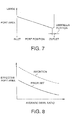
- the relationship between the port position and port area (cross section) of the second intake port 2 is as shown in Figure 7.
- the port area steadily shrinks from the inlet 5, and expands sharply at the umbrella portion 13. This situation is the same as with an ordinary intake port.
- the air density is gradually increased as it flows in the intake port downstream, thereby preventing separation and turbulence within the port and injecting the charge all at once from the outlet.
- the inner surface of the second intake port 2 is a smooth surface over its entire length, with no protrusions.
- the first intake port 1 includes the inlet 4, an inlet section 14 with a straight shape in plan view, a middle section 15 extending downstream from the inlet section 14 and protruding in a U-shape away from the second intake port with respect to the inlet section 14 (protruding to the left in the drawing), a part immediately before the outlet (referred to as "pre-outlet part” or “near-outlet part”) 16 extending downstream from the middle section 15, the outlet 7, and an umbrella portion 17 that smoothly links the pre-outlet part 16 and the outlet 7.
- the inlet section 14 extends in the intake port axis Cp direction in plan view.
- the middle section 15 is U-shaped (or counterclockwise turned C-shape), gradually moving away from the second intake port 2 starting at the inlet section 14, and then moving back toward the second intake port 2.
- the U-shape is inclined with respect to the direction perpendicular to the direction of the axis Cp of the first intake port so that the turning bottom of the U-shape approaches the crankshaft center C or the cylinder center Oc. This inclination angle is indicated by ⁇ .
- the middle section 15 is offset away from the second intake port 2, and the maximum offset length L thereof is at least 0.5 W but no more than 0.75 W, where W is the inlet width.
- the pre-outlet part 16 is oriented toward an area A between the outlet 8 of the second intake port and the cylinder inner wall 12a located upstream in the second intake port axial direction from the outlet 8. This is the hatched area A in Figure 1.
- the pre-outlet part 16 is directed at a specific angle ⁇ with respect to the first intake port axial direction from the location of the pre-outlet part 16 toward the inside of the cylinder 3.
- the pre-outlet part 16 is shaped such that its cross section perpendicular to the port center line C 1 is elliptical, i.e., flattened out. This cross sectional shape is hatched in the figure.
- the outlet 7 is located at a lower height than the inlet 4.
- the first intake port 1 links the inlet 4 and the outlet 7, but the inlet section 14 extends slightly upward from the inlet 4, and then drops downward at the subsequent middle section 15.
- the middle section 15 is curved downward from the inlet side toward the outlet side.
- the inlet 4 of the first intake port 1 is located at a lower height than the inlet 5 of the second intake port 2.
- the outlet 7 is invisible from the inlet 4.
- the outlet 7 is formed below a line B passing through the inlet 4 upper end and touching the bottom corner wall 18 of the middle section 15.
- the charge does not escape straight from the inlet 4 to the outlet 7, and the orientation can always be varied by the middle section 15.
- the relationship between the port position and port area of the first intake port 1 is also as shown in Figure 7.
- the port area steadily shrinks from the inlet 4 up to the end of the pre-outlet part 16, and expands sharply at the umbrella portion 17 up to the area of the outlet 7. This gradually increases the air density in the first intake port 1 as it flows downstream, and allows the charge to be injected all at once at the outlet 7.
- the inner surface of the first intake port 1 is also a smooth surface that is free of protrusions.
- the charge After passing through the inlet section 14, the charge curves in a U-shape along the middle section 15, and is injected from the outlet 7 in the direction defined by the near-outlet part 16.
- the outlet 7 faces down, but its length is negligible, so that the charge is injected in the orientation of the near-outlet part 16.
- the charge is injected in concentrated form toward the narrow area A.
- the area A is a dead space of the second intake port 2, and therefore the charge from the first intake port 1 does not interfere with the charge from the second intake port 2 in the area A.
- the charge of the first intake port 1 collides with the cylinder inner wall 12a (so that it can be said that the near-outlet part 16 is directed to the cylinder inner wall 12a), thereby accelerating the swirl S from the outermost peripheral position within the cylinder 3.
- the charges from the two ports do not cancel each other out, allowing for an effective increase in the swirl S.
- the first intake port 1 changes the entire amount of the charge to the orientation of the near-outlet part 16 ahead of time, and injects the entire amount from its outlet 7 in this orientation.
- the port area is gradually reduced and the air density is gradually raised, and further there are no protrusions on the port inner surface, the charge does not become turbulent or undergo separation midway, allowing the entire amount to be changed in its orientation along the port shape. Accordingly, there is no decrease in the effective port area, and a sufficient maximum charge amount can be obtained. Furthermore, since this entire amount is injected toward area A, the charge energy can be utilized to the maximum, affording greater swirl.
- the first intake port 1 could be called a third port which is definitely different from a known helical port and a tangential port.
- the near-outlet part 16 has a flattened cross sectional shape as mentioned above, the charge can be injected in a wider rather than taller shape, which further enhances the swirl increasing effect.
- the swirl is further strengthened as a whole by combination of the first and second intake ports 1 and 2.
- the second intake port 2 injects the charge toward the outermost peripheral location within the cylinder 3, and accelerates the charge (or swirl S) from the first intake port 2 at that location. It should be noted that this second intake port 2 may be used by itself, since even then the swirl increasing effect will be better than with a conventional straight tangential port.
- the first intake port 1 was actually fabricated and tested, whereupon better results were obtained than with a conventional intake port, as shown in Figure 8. Specifically, in the past, regardless of the shape of the port, the relationship between average swirl ratio and effective port area was constant, as indicated by the solid line. With the first intake port 1 discussed above, however, the average swirl ratio and effective port area were both better than the prior art. This means that a higher average swirl ratio will be obtained at a given flow rate, and a larger effective port area, that is, a higher intake efficiency and maximum charge amount, will be obtained at a given average swirl ratio. This confirmed the effectiveness of the first intake port 1, that is, achieving a high level for both intake amount and swirl.
- the charge from the first intake port 1 may be injected toward area A, but in some cases it may be impossible to orient the first intake port 1 in that direction because of the layout or other such factors. In such a case, the charge may be injected toward the outlet 8 of the second intake port 2. If so, there will be charge interference and the swirl increasing effect will drop somewhat, but the maximum intake amount will be sufficiently obtained for the first intake port 1. Also, it is still possible to accelerate the swirl S because the charge from the first intake port 1 after interference collides with the cylinder inner wall 12a and flows along this cylinder inner wall 12a. In this embodiment, however, there is believed to be very little charge interference because the charge from the outlet 8 of the second intake port 2 is injected downward at an angle toward the crankshaft center C. With this in mind as well, it is preferable for the angle ⁇ to be at least 90° but no more than 150°.
- VVT variable valve timing
- the inlet 4 of the first intake port 1 is located at the same height location as the inlet 5 of the second intake port 2.
- the plan view is the same as Figure 1.
- the height location of the inlet 4 of the first intake port 1 is changed to a higher location as compared with the first embodiment.
- the inlet section 14 descends gently downstream as shown in Figure 12, and the curvature of the middle section 15 is decreased.
- Everything else is the same as in the first embodiment, and those components that are the same in the figures are labeled the same reference numerals and will not be described again.
- second intake port 2 is a helical port.
- the passage ahead of the outlet 8 is constricted so that there will be a passage on the opposite side from the first intake port 1, and this portion is formed in a helical or spiral shape.
- the spiral flow injected from the outlet 8 has a rotation component in the same direction as the swirl S.
- the inner wall 20 located on the opposite side from the first intake port 1 extends straight ahead in the intake port axis Cp direction until the outlet 8, so that it does not stick out of the cylinder.
- the height locations of the inlet 4 of the first intake port 1 and the inlet 5 of the second intake port 2 may be the same or different. Further, the shape of the helical port and the type of the second intake port itself are not particularly restricted to those discussed above.
- the engine can be a gasoline engine, or the number of valves per cylinder can be changed (such as three valves).
- the effect of the present invention is that a powerful swirl can be generated under any circumstances, and high levels can be achieved for both the intake amount and swirl.
Applications Claiming Priority (3)
| Application Number | Priority Date | Filing Date | Title |
|---|---|---|---|
| JP36740499 | 1999-12-24 | ||
| JP2000263246A JP3807207B2 (ja) | 1999-12-24 | 2000-08-28 | 多弁吸気式エンジン |
| EP00128198A EP1111224B1 (de) | 1999-12-24 | 2000-12-21 | Brennkraftmaschine mit mehreren Ventilen |
Related Parent Applications (1)
| Application Number | Title | Priority Date | Filing Date |
|---|---|---|---|
| EP00128198A Division EP1111224B1 (de) | 1999-12-24 | 2000-12-21 | Brennkraftmaschine mit mehreren Ventilen |
Publications (1)
| Publication Number | Publication Date |
|---|---|
| EP1752644A1 true EP1752644A1 (de) | 2007-02-14 |
Family
ID=26581902
Family Applications (2)
| Application Number | Title | Priority Date | Filing Date |
|---|---|---|---|
| EP00128198A Expired - Lifetime EP1111224B1 (de) | 1999-12-24 | 2000-12-21 | Brennkraftmaschine mit mehreren Ventilen |
| EP06120247A Ceased EP1752644A1 (de) | 1999-12-24 | 2000-12-21 | Brennkraftmaschine mit mehreren Ventilen |
Family Applications Before (1)
| Application Number | Title | Priority Date | Filing Date |
|---|---|---|---|
| EP00128198A Expired - Lifetime EP1111224B1 (de) | 1999-12-24 | 2000-12-21 | Brennkraftmaschine mit mehreren Ventilen |
Country Status (5)
| Country | Link |
|---|---|
| US (1) | US6526940B2 (de) |
| EP (2) | EP1111224B1 (de) |
| JP (1) | JP3807207B2 (de) |
| CN (1) | CN1301916A (de) |
| DE (1) | DE60032323T2 (de) |
Families Citing this family (22)
| Publication number | Priority date | Publication date | Assignee | Title |
|---|---|---|---|---|
| ITTO20010660A1 (it) * | 2001-07-06 | 2003-01-06 | Fiat Ricerche | Motore diesel pluricilindrico con azionamento variabile delle valvole. |
| FR2846053B1 (fr) * | 2002-10-16 | 2007-01-05 | Renault Sa | Culasse pour cylindre de moteur a injection directe fonctionnant notamment selon le cycle diesel et moteur a combustion interne comportant une telle culasse |
| JP4325173B2 (ja) * | 2002-11-01 | 2009-09-02 | 三菱自動車工業株式会社 | 直噴式ディーゼルエンジン |
| KR20040041309A (ko) * | 2002-11-11 | 2004-05-17 | 현대자동차주식회사 | 스월 강화를 위한 엔진의 흡기포트 구조 |
| JP4680828B2 (ja) * | 2006-05-11 | 2011-05-11 | 本田技研工業株式会社 | エンジンの吸気ポ−ト構造 |
| JP4888330B2 (ja) | 2007-10-22 | 2012-02-29 | トヨタ自動車株式会社 | 直接噴射式の内燃機関 |
| EP2131025A1 (de) * | 2008-06-06 | 2009-12-09 | General Electric Company | Einlasskanäle für Verbrennungsmotoren |
| US8056525B2 (en) * | 2008-09-12 | 2011-11-15 | Ford Global Technologies | Induction system for internal combustion engine |
| JP5352445B2 (ja) * | 2009-12-28 | 2013-11-27 | 株式会社三井ハイテック | 積層鉄心の製造方法 |
| AT508074B1 (de) * | 2010-03-18 | 2011-09-15 | Avl List Gmbh | Zylinderkopf |
| GB2531214B (en) * | 2010-10-12 | 2016-08-24 | Gm Global Tech Operations Llc | An Intake Duct Arrangement for a Combustion Chamber of an Internal Combustion Engine |
| CN102207027B (zh) * | 2010-10-25 | 2013-03-13 | 浙江吉利汽车研究院有限公司 | 柴油机进气涡流调节结构 |
| US20140366837A1 (en) * | 2012-08-16 | 2014-12-18 | Gerald John Wawrzeniak | Split-cycle-engine multi-axis helical crossover passage with geometric dilution |
| US9719410B2 (en) * | 2012-12-26 | 2017-08-01 | Doosan Infracore Co., Ltd. | Engine intake port structure |
| KR102169031B1 (ko) * | 2013-09-25 | 2020-10-22 | 가부시끼 가이샤 구보다 | 엔진의 흡기 장치 |
| JP6288014B2 (ja) * | 2015-09-08 | 2018-03-07 | トヨタ自動車株式会社 | 内燃機関 |
| JP6923326B2 (ja) * | 2016-03-30 | 2021-08-18 | 本田技研工業株式会社 | 内燃機関 |
| DE102017112350A1 (de) * | 2017-06-06 | 2018-12-06 | Dr. Ing. H.C. F. Porsche Aktiengesellschaft | Zylinderkopf für eine Verbrennungskraftmaschine, Verbrennungskraftmaschine und Verfahren zum Betreiben einer Verbrennungskraftmaschine |
| KR102453360B1 (ko) * | 2017-12-18 | 2022-10-07 | 현대자동차 주식회사 | 흡기 포트 |
| KR20190072927A (ko) * | 2017-12-18 | 2019-06-26 | 현대자동차주식회사 | 흡기 포트 |
| JP2019127884A (ja) * | 2018-01-24 | 2019-08-01 | マツダ株式会社 | エンジンのシリンダヘッド |
| JP7106972B2 (ja) * | 2018-05-08 | 2022-07-27 | トヨタ自動車株式会社 | 内燃機関のシリンダヘッド |
Citations (7)
| Publication number | Priority date | Publication date | Assignee | Title |
|---|---|---|---|---|
| US3020896A (en) * | 1959-08-07 | 1962-02-13 | Maschf Augsburg Nuernberg Ag | Cylinder head with air intake passages |
| JPS5756621A (en) * | 1980-09-22 | 1982-04-05 | Toyota Motor Corp | Internal combustion engine |
| WO1986005237A1 (fr) * | 1985-03-05 | 1986-09-12 | Motoren-Werke Mannheim Ag Vorm. Benz Abt. Stat. Mo | Dispositif de chargement a turbulence et/ou a cyclone pour moteurs a combustion |
| US4703729A (en) * | 1986-10-14 | 1987-11-03 | Kubota Ltd. | Intake system with double intake ports for internal combustion engine |
| EP0527122A1 (de) * | 1991-08-07 | 1993-02-10 | AVL Gesellschaft für Verbrennungskraftmaschinen und Messtechnik mbH.Prof.Dr.Dr.h.c. Hans List | Mehrzylindrige Brennkraftmaschine mit innerer Gemischbildung |
| JPH1037751A (ja) | 1996-07-23 | 1998-02-10 | Toyota Motor Corp | 内燃機関の吸気装置 |
| AT3137U1 (de) * | 1998-09-11 | 1999-10-25 | Avl List Gmbh | Brennkraftmaschine mit zwei einlassventilen je zylinder |
Family Cites Families (16)
| Publication number | Priority date | Publication date | Assignee | Title |
|---|---|---|---|---|
| SE401239B (sv) * | 1972-05-10 | 1978-04-24 | List Hans | Forbrenningsmotor av insprutningstyp |
| DE2710321A1 (de) | 1977-03-09 | 1978-09-14 | Int Harvester Co | Brennkraftmaschine |
| JPS61104119A (ja) | 1984-10-26 | 1986-05-22 | Nissan Motor Co Ltd | 内燃機関の吸気装置 |
| BR8706074A (pt) | 1986-11-07 | 1988-06-14 | Elsbett L | Cabecote de cilindro aperfeicoado para motores a diesel |
| JPH0220729U (de) * | 1988-07-26 | 1990-02-13 | ||
| JPH0479935U (de) * | 1990-11-27 | 1992-07-13 | ||
| JP2531322B2 (ja) * | 1991-09-13 | 1996-09-04 | トヨタ自動車株式会社 | 内燃機関 |
| JP3328990B2 (ja) * | 1993-04-05 | 2002-09-30 | いすゞ自動車株式会社 | 多弁吸気式エンジン |
| DE69401829T2 (de) * | 1993-04-05 | 1997-09-18 | Isuzu Motors Ltd | Brennkraftmaschine mit mehreren Einlassventilen |
| JP3324189B2 (ja) | 1993-04-05 | 2002-09-17 | いすゞ自動車株式会社 | 多弁吸気式エンジン |
| JP3156471B2 (ja) | 1993-12-08 | 2001-04-16 | トヨタ自動車株式会社 | 内燃機関の吸気装置 |
| JP3561987B2 (ja) | 1994-12-07 | 2004-09-08 | いすゞ自動車株式会社 | 多弁吸気式エンジン |
| JP3518009B2 (ja) * | 1994-12-17 | 2004-04-12 | マツダ株式会社 | エンジンの吸気装置 |
| JPH08270453A (ja) * | 1995-03-31 | 1996-10-15 | Suzuki Motor Corp | 内燃機関の吸気装置 |
| DE19712357B4 (de) * | 1997-03-25 | 2004-05-06 | Harald Echtle | Verfahren zur Gemischbildung bei einer direkteinspritzenden Brennkraftmaschine |
| US6003485A (en) | 1997-06-10 | 1999-12-21 | Nissan Motor Co., Ltd. | Helical intake port for an internal combustion engine |
-
2000
- 2000-08-28 JP JP2000263246A patent/JP3807207B2/ja not_active Expired - Fee Related
- 2000-12-19 US US09/741,472 patent/US6526940B2/en not_active Expired - Lifetime
- 2000-12-21 DE DE60032323T patent/DE60032323T2/de not_active Expired - Lifetime
- 2000-12-21 EP EP00128198A patent/EP1111224B1/de not_active Expired - Lifetime
- 2000-12-21 EP EP06120247A patent/EP1752644A1/de not_active Ceased
- 2000-12-22 CN CN00136266A patent/CN1301916A/zh active Pending
Patent Citations (7)
| Publication number | Priority date | Publication date | Assignee | Title |
|---|---|---|---|---|
| US3020896A (en) * | 1959-08-07 | 1962-02-13 | Maschf Augsburg Nuernberg Ag | Cylinder head with air intake passages |
| JPS5756621A (en) * | 1980-09-22 | 1982-04-05 | Toyota Motor Corp | Internal combustion engine |
| WO1986005237A1 (fr) * | 1985-03-05 | 1986-09-12 | Motoren-Werke Mannheim Ag Vorm. Benz Abt. Stat. Mo | Dispositif de chargement a turbulence et/ou a cyclone pour moteurs a combustion |
| US4703729A (en) * | 1986-10-14 | 1987-11-03 | Kubota Ltd. | Intake system with double intake ports for internal combustion engine |
| EP0527122A1 (de) * | 1991-08-07 | 1993-02-10 | AVL Gesellschaft für Verbrennungskraftmaschinen und Messtechnik mbH.Prof.Dr.Dr.h.c. Hans List | Mehrzylindrige Brennkraftmaschine mit innerer Gemischbildung |
| JPH1037751A (ja) | 1996-07-23 | 1998-02-10 | Toyota Motor Corp | 内燃機関の吸気装置 |
| AT3137U1 (de) * | 1998-09-11 | 1999-10-25 | Avl List Gmbh | Brennkraftmaschine mit zwei einlassventilen je zylinder |
Also Published As
| Publication number | Publication date |
|---|---|
| US20010006056A1 (en) | 2001-07-05 |
| DE60032323D1 (de) | 2007-01-25 |
| EP1111224B1 (de) | 2006-12-13 |
| CN1301916A (zh) | 2001-07-04 |
| DE60032323T2 (de) | 2007-05-31 |
| US6526940B2 (en) | 2003-03-04 |
| JP2001241331A (ja) | 2001-09-07 |
| JP3807207B2 (ja) | 2006-08-09 |
| EP1111224A2 (de) | 2001-06-27 |
| EP1111224A3 (de) | 2002-02-27 |
Similar Documents
| Publication | Publication Date | Title |
|---|---|---|
| EP1111224B1 (de) | Brennkraftmaschine mit mehreren Ventilen | |
| EP1405993B1 (de) | Einlassanlage für Brennkraftmaschine | |
| EP1464805B1 (de) | Luftansaugvorrichtung für Brennkraftmaschine | |
| AU632710B2 (en) | Improved intake valve for internal combustion engine | |
| EP1344926B1 (de) | Einlasskanal einer Brennkraftmaschine | |
| EP1464806B1 (de) | Ansaugvorrichtung für eine Brennkraftmaschine | |
| US6904891B2 (en) | Intake system of internal combustion engine | |
| EP1405994B1 (de) | Einlassanlage für Brennkraftmaschine | |
| EP0711906A2 (de) | Brennkraftmaschine | |
| US7270109B2 (en) | Internal combustion engine | |
| US5605123A (en) | Intake port structure in internal combustion engine | |
| JPH06212983A (ja) | エンジンの吸気制御装置 | |
| JP4971242B2 (ja) | 内燃機関の吸気装置 | |
| JPH08200023A (ja) | 内燃機関のシリンダヘッド構造 | |
| JPH0415939Y2 (de) | ||
| JP3014802B2 (ja) | エンジンの吸気構造 | |
| JP3861837B2 (ja) | 内燃機関の吸気装置 | |
| JPH0988616A (ja) | 内燃機関の吸気装置 | |
| WO1997014879A1 (en) | Internal combustion diesel engine for motor-vehicles, with direct injection | |
| JPS60198331A (ja) | エンジンの吸気装置 | |
| JP2004308469A (ja) | 内燃機関の吸気装置 | |
| JPH01113516A (ja) | 吸気2弁式エンジンの吸気装置 | |
| JP2004324593A (ja) | 内燃機関の吸気装置 | |
| JPH06137153A (ja) | エンジンの吸気装置 | |
| JPS60162017A (ja) | エンジンの吸気装置 |
Legal Events
| Date | Code | Title | Description |
|---|---|---|---|
| PUAI | Public reference made under article 153(3) epc to a published international application that has entered the european phase |
Free format text: ORIGINAL CODE: 0009012 |
|
| AC | Divisional application: reference to earlier application |
Ref document number: 1111224 Country of ref document: EP Kind code of ref document: P |
|
| AK | Designated contracting states |
Kind code of ref document: A1 Designated state(s): AT BE BG CH CY CZ DE DK EE ES FI FR GB GR HU IE IS IT LI LT LU LV MC NL PL PT RO SE SI SK TR |
|
| AX | Request for extension of the european patent |
Extension state: AL BA HR MK YU |
|
| RIN1 | Information on inventor provided before grant (corrected) |
Inventor name: ICHIKAWA, HIROYUKI,C/O ISUZU ENGINEERING CO., LTD. |
|
| 17P | Request for examination filed |
Effective date: 20070614 |
|
| AKX | Designation fees paid |
Designated state(s): DE FR GB |
|
| 17Q | First examination report despatched |
Effective date: 20080918 |
|
| APBK | Appeal reference recorded |
Free format text: ORIGINAL CODE: EPIDOSNREFNE |
|
| APBN | Date of receipt of notice of appeal recorded |
Free format text: ORIGINAL CODE: EPIDOSNNOA2E |
|
| APBR | Date of receipt of statement of grounds of appeal recorded |
Free format text: ORIGINAL CODE: EPIDOSNNOA3E |
|
| APAF | Appeal reference modified |
Free format text: ORIGINAL CODE: EPIDOSCREFNE |
|
| APBT | Appeal procedure closed |
Free format text: ORIGINAL CODE: EPIDOSNNOA9E |
|
| STAA | Information on the status of an ep patent application or granted ep patent |
Free format text: STATUS: THE APPLICATION HAS BEEN REFUSED |
|
| 18R | Application refused |
Effective date: 20110128 |