EP1746793A2 - Gerät und Verfahren zum Schätzen des Versatzes der Abtastfrequenz für ein OFDM-System - Google Patents
Gerät und Verfahren zum Schätzen des Versatzes der Abtastfrequenz für ein OFDM-System Download PDFInfo
- Publication number
- EP1746793A2 EP1746793A2 EP06012412A EP06012412A EP1746793A2 EP 1746793 A2 EP1746793 A2 EP 1746793A2 EP 06012412 A EP06012412 A EP 06012412A EP 06012412 A EP06012412 A EP 06012412A EP 1746793 A2 EP1746793 A2 EP 1746793A2
- Authority
- EP
- European Patent Office
- Prior art keywords
- phase
- frequency offset
- sampling frequency
- pilot subcarriers
- sampling
- Prior art date
- Legal status (The legal status is an assumption and is not a legal conclusion. Google has not performed a legal analysis and makes no representation as to the accuracy of the status listed.)
- Withdrawn
Links
Images




Classifications
-
- H—ELECTRICITY
- H04—ELECTRIC COMMUNICATION TECHNIQUE
- H04L—TRANSMISSION OF DIGITAL INFORMATION, e.g. TELEGRAPHIC COMMUNICATION
- H04L27/00—Modulated-carrier systems
- H04L27/26—Systems using multi-frequency codes
- H04L27/2601—Multicarrier modulation systems
- H04L27/2647—Arrangements specific to the receiver only
- H04L27/2655—Synchronisation arrangements
- H04L27/2657—Carrier synchronisation
-
- H—ELECTRICITY
- H04—ELECTRIC COMMUNICATION TECHNIQUE
- H04L—TRANSMISSION OF DIGITAL INFORMATION, e.g. TELEGRAPHIC COMMUNICATION
- H04L27/00—Modulated-carrier systems
- H04L27/26—Systems using multi-frequency codes
- H04L27/2601—Multicarrier modulation systems
- H04L27/2647—Arrangements specific to the receiver only
- H04L27/2655—Synchronisation arrangements
- H04L27/2668—Details of algorithms
- H04L27/2673—Details of algorithms characterised by synchronisation parameters
- H04L27/2675—Pilot or known symbols
-
- H—ELECTRICITY
- H04—ELECTRIC COMMUNICATION TECHNIQUE
- H04L—TRANSMISSION OF DIGITAL INFORMATION, e.g. TELEGRAPHIC COMMUNICATION
- H04L25/00—Baseband systems
- H04L25/02—Details ; arrangements for supplying electrical power along data transmission lines
- H04L25/0202—Channel estimation
- H04L25/0224—Channel estimation using sounding signals
-
- H—ELECTRICITY
- H04—ELECTRIC COMMUNICATION TECHNIQUE
- H04L—TRANSMISSION OF DIGITAL INFORMATION, e.g. TELEGRAPHIC COMMUNICATION
- H04L27/00—Modulated-carrier systems
- H04L27/01—Equalisers
-
- H—ELECTRICITY
- H04—ELECTRIC COMMUNICATION TECHNIQUE
- H04L—TRANSMISSION OF DIGITAL INFORMATION, e.g. TELEGRAPHIC COMMUNICATION
- H04L27/00—Modulated-carrier systems
- H04L27/26—Systems using multi-frequency codes
- H04L27/2601—Multicarrier modulation systems
- H04L27/2647—Arrangements specific to the receiver only
- H04L27/2655—Synchronisation arrangements
- H04L27/2668—Details of algorithms
- H04L27/2673—Details of algorithms characterised by synchronisation parameters
- H04L27/2676—Blind, i.e. without using known symbols
- H04L27/2679—Decision-aided
Definitions
- the present invention relates to a sampling frequency offset estimation apparatus and method to be applied to an orthogonal frequency division multiplexing (OFDM) system. More particularly, the present invention relates to a sampling frequency offset estimation apparatus and a method estimating a phase shift of each pilot subcarrier of a received signal to estimate a sampling frequency offset.
- OFDM orthogonal frequency division multiplexing
- an orthogonal frequency division multiplexing OFDM method a data stream input in series is converted into parallel data of a predetermined block unit, parallel symbols are multiplexed into orthogonal carrier frequencies so as to convert a wideband transmission into a narrowband parallel transmission.
- Such an OFDM method is robust to multi-path fading in a wireless communication environment and enables a high speed data transmission.
- a pilot subcarrier is used to track a sampling frequency offset in an OFDM system.
- pilot symbol data which is data known to a transmitter and a receiver, is transmitted so that the receiver uses the data to perform synchronization.
- the pilot subcarrier is divided into two sets. In other words, there are a pilot position in a negative subcarrier and a pilot position in a positive subcarrier.
- the sampling frequency offset is tracked using information as to a linear relationship between an offset and a phase rotation occurring due to an index of the pilot subcarrier.
- FIGS. 1A and 1B are views illustrating an effect of a sampling frequency offset in an OFDM system.
- FIG. 1A is a view illustrating distortions of a phase and an amplitude at 30 parts per million (ppm) at which an 0.5 initial time offset occurs
- FIG. 1B is a view illustrating distortions of a phase and an amplitude at 30 ppm at which a 0.5 initial time offset and a one-sample symbol time offset occur.
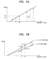
- FIGS. 2A and 2B are graphs illustrating an estimation of a sampling frequency offset in a related art OFDM system.
- FIG. 2A is a graph illustrating an estimation of a sampling frequency offset using a phase difference between pilot subcarriers.
- a sampling time offset can be computed to estimate a phase slope so as to estimate a sampling frequency offset.
- FIG. 2B is a graph illustrating an estimation of a sampling frequency offset using an estimation of a variation in a phase difference between pilot subcarriers with time.
- ⁇ p,p +1 denotes a variation in a phase slope computed using a phase difference between p th and p+1 th pilots in 1 th and 1+1 th OFDM symbols, ⁇ k denotes a variation
- the variation in the phase slope may be estimated using a phase difference between p th and p+1 th pilots in a symbol delayed by D instead of the 1+1 th OFDM symbol and an 1 th symbol.
- FIG. 3 is a graph illustrating a relationship between a symbol index and a phase estimated by a conventional sampling frequency offset estimation method.
- S denotes a point of time at which a one sample shifts and at which a distortion occurring due to a sampling frequency offset is required to be compensated for.
- a phase of a sampling time offset linearly increases with an increase in time in area L.
- a pilot subcarrier having a phase equal to or more - ⁇ or ⁇ with time after the area L thus, the linearity of a phase between pilot subcarriers is not established.
- a wrong sampling frequency offset may be estimated.
- S denotes a point of time at which an average phase slope computed by a plurality of pilot subcarriers varies by one sample and at which a sample must be added or deleted due to an effect of noise and thus has a large standard variation.
- a point of time at which a one sample is added or deleted cannot be precisely detected.
- Illustrative, non-limiting embodiments of the present invention overcome the above disadvantages and other disadvantages not described above. Also, the present invention is not required to overcome the disadvantages described above, and an illustrative, non- limiting embodiment of the present invention may not overcome any of the problems described above.
- the present invention provides a sampling frequency offset estimation apparatus and method applied to an OFDM system and capable of computing a phase shift of each pilot subcarrier, not an average phase shift of pilot subcarriers, to precisely estimate a sampling frequency offset.
- a sampling frequency offset estimation apparatus including: an analog-to-digital converter (ADC) sampling a received signal based on a predetermined sampling frequency; a Fast Fourier Transform (FFT) unit transforming the sampled received signal into a frequency domain; a phase calculator calculating phase shifts of pilot subcarriers of the received signal which has been transformed into the frequency domain; a determiner calculating phase shift reaching times at which samples of the pilot subcarriers shift due to the phase shift; a time offset calculator calculating a sampling time offset using the pilot subcarriers; and a frequency offset calculator calculating a sampling frequency offset based on the phase shift reaching times and the sampling time offset.
- ADC analog-to-digital converter
- FFT Fast Fourier Transform
- the sampling frequency offset estimation apparatus may further include a storage storing the pilot subcarriers of the received signal which has been transformed into the frequency domain.
- the determiner may detect a symbol index at which phases of the pilot subcarriers are equal to or more than ⁇ or equal to or less than - ⁇ to calculate the phase shift reaching times.
- an OFDM system using the sampling frequency offset estimation apparatus there is provided an OFDM system using the sampling frequency offset estimation apparatus.
- the OFDM system may further include an equalizer correcting a phase distortion of the received signal based on the estimated sampling frequency offset.
- the OFDM system may further include a rob/stuff unit robbing or stuffing one sample based on the estimated sampling frequency offset.
- a sampling frequency offset estimation method including: transforming a received signal sampled based on a predetermined sampling frequency offset into a frequency domain; and calculating phase shifts of pilot subcarriers of the received signal which has been transformed into the frequency domain and calculating a sampling frequency offset based on phase shift reaching times at which samples of the pilot subcarriers shift due to a phase shift.
- the calculating of the sampling frequency offset may include: calculating the phase shifts of the pilot subcarriers of the received signal which has been transformed into the frequency domain; calculating the phase shift reaching times at which the samples of the pilot subcarriers shift due to the phase shift; calculating sampling time offsets using the pilot subcarriers; and calculating a sampling frequency offset based on the phase shift reaching times and the sampling time offsets.
- the sampling frequency offset estimation method may further include storing the pilot subcarriers of the received signal which has been transformed into the frequency domain.
- the phase shift reaching times may be calculated by detecting a symbol index at which phases of the pilot subcarriers are equal to or more than ⁇ or equal to or less than - ⁇ .
- FIGS. 1A and 1B are views illustrating an influence of a sampling frequency offset in an OFDM system
- FIGS. 2A and 2B are graphs illustrating an estimation of a sampling frequency offset in a related art OFDM system
- FIG. 3 is a graph illustrating a relationship between a symbol index and a phase estimated by a conventional sampling frequency offset estimation method
- FIG. 4 is a block diagram of an OFDM system to which a sampling frequency offset estimation apparatus is applied according to an exemplary embodiment of the present invention
- FIG. 5 is a flowchart of a sampling frequency offset estimation method to be applied to an OFDM system according to an exemplary embodiment of the present invention
- FIG. 6 is a graph illustrating the sampling frequency offset estimation method of FIG. 5 in detail.
- FIGS. 7A and 7B are graph illustrating results of a simulation performed with respect to performances of the conventional sampling frequency offset estimation method and the sampling frequency offset estimation method according to an exemplary embodiment of the present invention.
- a rotation of an OFDM system caused by a sampling frequency offset may be corrected using two methods.
- the first method is a synchronization sampling method by which a sampling frequency of a receiver ADC is changed to correct a rotation of an OFDM system.
- the second method is an asynchronization sampling method by which a subcarrier is re-rotated to correct a rotation of an OFDM system after Discrete Fourier Transform (DFT).
- DFT Discrete Fourier Transform
- sampling frequency offset estimation to be applied to an asynchronization sampling method of correcting a rotation phenomenon after sampling a received signal using a sampling frequency and then performing DFT on the received signal.
- FIG. 4 is a block diagram of an OFDM system to which a sampling frequency offset estimation apparatus is applied according to an exemplary embodiment of the present invention.
- the OFDM system includes an ADC 100, a rob/stuff unit 200, an FFT unit 300, an equalizer 400, a storage 500, and a frequency offset estimator 600.
- the ADC 100 samples a received signal using a predetermined sampling frequency generated by an oscillator (not shown).
- the FFT unit 300 transforms the sampled received signal into a frequency domain.
- the storage 500 stores a pilot subcarrier of the received signal which has been transformed into the frequency domain.
- a receiver of the OFDM system receives a pilot symbol that is data a transceiver knows about to perform a synchronization so as to additionally store a pilot subcarrier used for a sampling frequency offset estimation.
- the frequency offset estimator 600 includes a phase calculator 610, a determiner 620, and an offset calculator 630 and estimates sampling frequency and time offsets based on a phase shift of each of stored pilot subcarrier.
- the phase calculator 610 calculates phase shifts of pilot subcarriers of the received signal which has been transformed into the frequency domain. Since the pilot subcarriers have different phase shift rates according to sampling frequency offsets, the phase calculator 610 calculates a phase shift of each of the pilot subcarriers.
- the determiner 620 estimates a time at which the phase of each of the pilot subcarriers sharply varies.
- the determiner 620 estimates a phase shift reaching time at which the phase of each of the pilot subcarriers is equal to or more than ⁇ or equal to or less than - ⁇ , i.e., a 1-sample shifts.
- the sampling frequency offset has a linear relationship with a phase rotation occurring due to indexes of the pilot subcarriers. Thus, an upper most pilot subcarrier positioned outside one symbol reaches a time equal to or more than ⁇ or equal to or less than - ⁇ .
- the offset calculator 630 calculates the sampling time offset based on the indexes of the pilot subcarriers and calculates the sampling frequency offset using the calculated sampling time offset and the estimated phase shift reaching time.
- the equalizer 400 corrects a distortion of a phase using the sampling time offset estimated by the frequency offset estimator 600.
- the rob/stuff unit 200 stuffs a copied sample or robs one sample of a signal based on the sampling frequency offset estimated by the frequency offset estimator 600. A variation in a sampling instant becomes gradually larger than a sampling period due to the sampling frequency offset. Thus, the rob/stuff unit 200 detects a position in which one sample shifts to stuff or rob a sample so as to correct a distortion caused by the sampling frequency offset.
- FIG. 5 is a flowchart of a sampling frequency offset estimation method to be applied to an OFDM system according to an exemplary embodiment of the present invention.
- a phase shift of a pilot subcarrier of a received signal that is data a transceiver knows about is calculated.
- the received signal is sampled using a predetermined sampling frequency and then transformed into a frequency domain using FFT.
- Phase shifts of pilot subcarriers of the received signal which has been transformed into the frequency domain are calculated based on indexes of the pilot subcarriers.
- the pilot subcarriers have different phase shift rates according to sampling frequency offsets and have linear relationships with phase rotation caused by the sampling frequency offset and the indexes of the pilot subcarriers.
- positions in which the phases of the pilot subcarriers are equal to or more than ⁇ or equal to or less than - ⁇ vary with the indexes of the pilot subcarriers.
- an upper pilot subcarrier outside one symbol reaches a position in which a phase is equal to or more than ⁇ or equal to or less than - ⁇
- a phase shift reaching time at which a phase is equal to or more than ⁇ or equal to or less than - ⁇ is calculated in operation S930.
- the phase shift reaching time is calculated using a symbol index of a position in which a phase is equal to or more than ⁇ or equal to or less than - ⁇ , a sampling time section, and a number of samples per symbol.
- a time at which a phase is equal to or more than ⁇ or equal to or less than - ⁇ is a time at which one sample shifts.
- the phase shift reaching time at which the one sample shifts can be detected to stuff or rob a sample based on the detected phase shift reaching time so as to correct a distortion caused by the sampling frequency offset.
- phase shifts of the pilot subcarriers are calculated with increasing symbol index, and then a sampling time offset is calculated in operation S940.
- the sampling time offset may be calculated based on the indexes of the pilot subcarriers and FFT Window Size.
- a sampling frequency offset is calculated based on the phase shift reaching time calculated in operation S930 and the sampling time offset calculated in operation S940.
- the sampling frequency offset may be calculated by dividing the sampling time offset by the phase shift reaching time.
- a phase shift of an independent pilot subcarrier can be calculated differently from a case where an average phase shift of pilot subcarriers so as to precisely find a time at which the 1-sample is stuffed or robbed
- sampling frequency offsets of a plurality of pilot subcarriers may be calculated to correct a phase shift caused by the sampling frequency offsets.
- the phase shift may be corrected using only the sampling frequency offset of an upper pilot subcarrier of which one sample shifts.
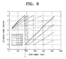
- FIG. 6 is a graph illustrating the sampling frequency offset estimation method in detail.
- the horizontal axis denotes an OFDM symbol index
- the vertical axis denotes a phase estimated with respect to an index of each pilot subcarrier.
- a rotation angle occurring with each pilot subcarrier during receiving of an OFDM signal varies with an index of each pilot subcarrier and an OFDM symbol index.
- the rotation angle is the largest at a pilot subcarrier position outside and increases in consecutive OFDM symbols. In other words, a sampling offset is generally very small. However, a rotation angle increases with an increase in a symbol index. Thus, precise demodulating may be impossible.
- A denotes an OFDM symbol index when the pilot subcarrier #1 reaches the phase shift reaching time.
- the OFDM symbol index is "182" when the pilot subcarrier #1 reaches the phase shift reaching time.
- a sampling time offset of each pilot subcarrier is calculated using an index of each pilot subcarrier and FFT Window Size as in Equation 6 as described in operation S940.
- Equation 6 ⁇ 1 N 2 ⁇ 55 wherein ⁇ 1 denotes a sampling time offset of the pilot subcarrier #1, N denotes FFT Window Size, and "55" denotes an index of the pilot subcarrier #1.
- a sampling frequency offset is calculated using the phase shift reaching time and the sampling time offset as described in operation S950.
- each sampling frequency offset may be calculated using each pilot subcarrier to stuff or rob a sample so as to correct a phase shift caused by the sampling frequency offset.
- only a sampling frequency offset of an upper pilot subcarrier of a plurality of subcarriers reaching a phase shift reaching time may be calculated.
- the sampling frequency offset of the pilot subcarrier that is the upper pilot subcarrier calculated using Equations 4, 6, and 8 is "-40 ppm.”
- a sample may be stuffed into the pilot subcarrier per 250 samples so as to correct a phase distortion caused by the sampling frequency offset.
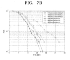
- FIGS. 7A and 7B are graphs illustrating results of a simulation performed with respect to performances of the conventional sampling frequency offset estimation method and the sampling frequency offset estimation method of the present invention.
- FIG. 7A is a graph illustrating a mean square error (MSE) with respect to a variation in a signal-to-noise rate (SNR)
- FIG. 7B is a graph illustrating a packet error rate (PER) with respect to an SNR.
- MSE mean square error
- SNR signal-to-noise rate
- PER packet error rate
- a sampling frequency offset is "0ppm,” “-10ppm,” “-20ppm,” or "-40ppm," an MSE as shown in FIG. 7A can be obtained.
- the MSE obtained by the sampling frequency offset estimation method of the present invention is more reduced than the MSE obtained by the conventional sampling frequency offset estimation method.
- the sampling frequency offset is "-10ppm,” “-20ppm,” “-40ppm,” a PER as shown in FIG. 7B can be obtained.
- the PER obtained by the sampling frequency offset estimation method of the present invention is more reduced than the PER obtained by the conventional sampling frequency offset estimation method.
- a sampling rate is set to 528 MHz
- an OFDM symbol size is set to "165”
- a data rate is set to 53.3 Mpbs.
- a payload size is set to 1024 bytes
- a multi-path channel model is set to CM1.
- a phase shift of each pilot subcarrier can be calculated to precisely estimate a sampling frequency offset. Also, a phase distortion caused by the sampling frequency offset can be precisely corrected.
Landscapes
- Engineering & Computer Science (AREA)
- Computer Networks & Wireless Communication (AREA)
- Signal Processing (AREA)
- Power Engineering (AREA)
- Synchronisation In Digital Transmission Systems (AREA)
Applications Claiming Priority (1)
| Application Number | Priority Date | Filing Date | Title |
|---|---|---|---|
| KR1020050065526A KR100719112B1 (ko) | 2005-07-19 | 2005-07-19 | Ofdm 시스템에 적용되는 샘플링 주파수 오차 추정장치및 그 방법 |
Publications (1)
| Publication Number | Publication Date |
|---|---|
| EP1746793A2 true EP1746793A2 (de) | 2007-01-24 |
Family
ID=37054798
Family Applications (1)
| Application Number | Title | Priority Date | Filing Date |
|---|---|---|---|
| EP06012412A Withdrawn EP1746793A2 (de) | 2005-07-19 | 2006-06-16 | Gerät und Verfahren zum Schätzen des Versatzes der Abtastfrequenz für ein OFDM-System |
Country Status (5)
| Country | Link |
|---|---|
| US (1) | US7702024B2 (de) |
| EP (1) | EP1746793A2 (de) |
| JP (1) | JP4320026B2 (de) |
| KR (1) | KR100719112B1 (de) |
| CN (1) | CN100591064C (de) |
Cited By (1)
| Publication number | Priority date | Publication date | Assignee | Title |
|---|---|---|---|---|
| CN103905361A (zh) * | 2012-12-25 | 2014-07-02 | 普天信息技术研究院有限公司 | 一种ofdm系统中的采样频率同步方法 |
Families Citing this family (24)
| Publication number | Priority date | Publication date | Assignee | Title |
|---|---|---|---|---|
| US8363757B1 (en) * | 1999-10-12 | 2013-01-29 | Qualcomm Incorporated | Method and apparatus for eliminating the effects of frequency offsets in a digital communication system |
| CN101136881B (zh) * | 2006-08-31 | 2012-10-10 | 世意法(北京)半导体研发有限责任公司 | 一种ofdma上行链路接收机和估计载波频偏的方法 |
| US20080117953A1 (en) * | 2006-11-20 | 2008-05-22 | Yu-Min Chuang | Frequency offset estimation circuit of receiving device of wireless transmission system |
| KR100874919B1 (ko) * | 2007-03-12 | 2008-12-19 | 삼성전자주식회사 | 샘플링 오프셋 추정 장치 및 샘플링 오프셋 추정 방법 |
| CN101277284B (zh) * | 2007-03-29 | 2012-12-26 | 深圳赛意法微电子有限公司 | 在drm中的采样时钟频率偏移量估计的方法及集成芯片 |
| US8045628B2 (en) * | 2007-10-18 | 2011-10-25 | Nokia Corporation | Digital video broadcast service discovery |
| CN101551790B (zh) * | 2008-04-03 | 2014-11-05 | 中兴通讯股份有限公司 | 应用于通信领域的快速傅立叶变换实现方法及装置 |
| CN101267423B (zh) * | 2008-05-09 | 2011-07-20 | 哈尔滨工业大学 | 在超宽带系统中利用分数傅立叶域估计时钟频偏的方法 |
| CN101789807B (zh) * | 2008-07-18 | 2014-04-16 | 俊茂微电子(上海)有限公司 | 频偏估计方法、装置以及通信设备 |
| KR101018140B1 (ko) * | 2009-02-02 | 2011-02-25 | 성균관대학교산학협력단 | Ofdm 시스템의 샘플링 주파수 동기 장치 |
| WO2010099808A1 (en) * | 2009-03-06 | 2010-09-10 | Telefonaktiebolaget Lm Ericsson (Publ) | A method of and equipment for compensating carrier frequency offset in an orthogonal frequency division multiplexing wireless radio transmission system |
| DE112010004177T5 (de) * | 2009-10-29 | 2012-12-20 | Sony Corporation | Empfangsvorrichtung für ein Hochfrequenzbildgebungssystem |
| US8660013B2 (en) | 2010-04-12 | 2014-02-25 | Qualcomm Incorporated | Detecting delimiters for low-overhead communication in a network |
| CN102790737B (zh) * | 2011-05-17 | 2017-11-28 | 中兴通讯股份有限公司 | 一种系统的同步方法及装置 |
| US8952838B2 (en) * | 2011-08-19 | 2015-02-10 | Lumedyne Technologies, Inc. | Time domain switched analog-to-digital converter apparatus and methods |
| CN102333370B (zh) * | 2011-08-31 | 2015-11-18 | 华南理工大学 | Ofdm系统中基于抽除/补偿机制的抽样时钟同步方法 |
| CN103095638B (zh) * | 2012-12-19 | 2016-06-08 | 西安电子科技大学 | 一种多径衰落信道下ofdm系统的采样频率偏移盲估算方法 |
| CN103281282B (zh) * | 2013-06-13 | 2016-04-06 | 湖南国科微电子股份有限公司 | 一种dvb-t2系统中频偏估计的方法 |
| US9160599B2 (en) * | 2013-08-12 | 2015-10-13 | Samsung Electronics Co., Ltd | Method and apparatus for channel smoothing and estimation in OFDM system |
| CN104601509B (zh) * | 2013-10-31 | 2018-04-27 | 富士通株式会社 | 多载波调制信号的定时同步装置及方法 |
| CN105099975B (zh) | 2014-04-24 | 2019-04-16 | 富士通株式会社 | 信道均衡和跟踪装置、方法以及接收机 |
| CN105610755B (zh) * | 2015-12-21 | 2020-05-26 | 航天恒星科技有限公司 | 一种突发信号的频偏估计方法及装置 |
| SG11201902729VA (en) | 2018-01-22 | 2019-08-27 | Radius Co Ltd | Receiver method, receiver, transmission method, transmitter, and transmitter-receiver system |
| CN110031675A (zh) * | 2019-04-19 | 2019-07-19 | 南京大学 | 一种数采系统实际采样频率的测量方法 |
Family Cites Families (9)
| Publication number | Priority date | Publication date | Assignee | Title |
|---|---|---|---|---|
| JPH11205275A (ja) | 1998-07-09 | 1999-07-30 | Toshiba Corp | Ofdm受信装置 |
| KR100313860B1 (ko) * | 1998-07-30 | 2001-12-12 | 윤종용 | Ofdm 전송 방식에서 미세 주파수 복원장치 및 그 방법 |
| JP2000151545A (ja) | 1998-11-06 | 2000-05-30 | Sony Corp | 復調装置および方法、並びに提供媒体 |
| JP3851017B2 (ja) | 1999-04-06 | 2006-11-29 | 日本放送協会 | Ofdm復調装置 |
| KR100488802B1 (ko) * | 2002-12-09 | 2005-05-12 | 한국전자통신연구원 | 직교 주파수 분할 다중화 무선 통신 시스템에서의 반송파주파수 오차와 샘플링 주파수 오차 추적 방법 및 그 장치 |
| TWI252656B (en) * | 2003-03-21 | 2006-04-01 | Realtek Semiconductor Corp | Sampling clock compensation device of multi-carrier system and method thereof |
| US7333548B2 (en) * | 2003-11-10 | 2008-02-19 | Mediatek Inc. | Phase and frequency drift compensation in Orthogonal Frequency Division Multiplexing systems |
| KR100983273B1 (ko) * | 2003-12-22 | 2010-09-24 | 엘지전자 주식회사 | Dmb 수신기의 주파수 복구 장치 및 방법 |
| CN1719818B (zh) | 2005-07-08 | 2010-06-23 | 广州海格通信集团股份有限公司 | 一种正交频分复用系统的采样频率偏差跟踪信号处理装置及方法 |
-
2005
- 2005-07-19 KR KR1020050065526A patent/KR100719112B1/ko not_active Expired - Fee Related
-
2006
- 2006-06-16 EP EP06012412A patent/EP1746793A2/de not_active Withdrawn
- 2006-07-04 CN CN200610095760A patent/CN100591064C/zh not_active Expired - Lifetime
- 2006-07-19 JP JP2006197325A patent/JP4320026B2/ja not_active Expired - Lifetime
- 2006-07-19 US US11/488,696 patent/US7702024B2/en active Active
Cited By (1)
| Publication number | Priority date | Publication date | Assignee | Title |
|---|---|---|---|---|
| CN103905361A (zh) * | 2012-12-25 | 2014-07-02 | 普天信息技术研究院有限公司 | 一种ofdm系统中的采样频率同步方法 |
Also Published As
| Publication number | Publication date |
|---|---|
| JP4320026B2 (ja) | 2009-08-26 |
| US7702024B2 (en) | 2010-04-20 |
| KR100719112B1 (ko) | 2007-05-17 |
| CN100591064C (zh) | 2010-02-17 |
| JP2007028636A (ja) | 2007-02-01 |
| US20070019763A1 (en) | 2007-01-25 |
| CN1901527A (zh) | 2007-01-24 |
| KR20070010721A (ko) | 2007-01-24 |
Similar Documents
| Publication | Publication Date | Title |
|---|---|---|
| US7702024B2 (en) | Sampling frequency offset estimation apparatus and method for OFDM system | |
| EP1689140A1 (de) | Vorrichtung und Verfahren zur Kompensation von Frequenzversatz in einem drahtlosen Kommunikationssystem | |
| US7215636B2 (en) | Method of determining training signal in OFDM, and apparatus and method for receiving OFDM signal using the training signal | |
| KR100865938B1 (ko) | 무선 통신 시스템의 수신기에서 캐리어 주파수 옵셋 추정및 보상을 위한 장치 및 데이터 수신 방법 | |
| CN102694763B (zh) | 一种用于td-lte系统整数倍频偏估计的方法 | |
| EP1746794B1 (de) | Pfadselektion in einer OFDM Vorrichtung | |
| US8559546B2 (en) | Methods and an apparatus for estimating a residual frequency error in a comunications system | |
| US7627049B2 (en) | Sampling frequency offset tracking method and OFDM system using the same | |
| KR20030016121A (ko) | 대칭형 프리앰블 생성방법 및 대칭형 프리앰블을 적용한오에프디엠 신호의 심볼/주파수 동기 방법 | |
| US20160020936A1 (en) | System and method for frequency synchronization of doppler-shifted subcarriers | |
| KR20040062617A (ko) | 주파수 오류 검출 방법과 그 장치, 복소수 프리앰블신호의 설계 방법 및 컴퓨터 판독 가능 기록 매체 | |
| KR100719111B1 (ko) | Ofdm 시스템에 적용되는 위상잡음 보상장치 및 그 방법 | |
| EP2566123B1 (de) | Ausgleichsvorrichtungen und verfahren zum erkennen und ausgleichen von abtasttaktverschiebungen | |
| US8433014B2 (en) | Receiving apparatus and receiving method | |
| Czylwik | Low overhead pilot-aided synchronization for single carrier modulation with frequency domain equalization | |
| KR101541026B1 (ko) | Ofdm 수신기 | |
| US7639750B2 (en) | Phase tracking method and device thereof | |
| KR100626644B1 (ko) | 직교 주파수 분할 다중화 통신시스템에서 주파수 및 시간옵셋 추정 방법과 그를 이용한 장치 | |
| EP2200246A1 (de) | Verfahren und Vorrichtung zur Bestimmung des Phasenrauschens in einem OFDM-Übertragungssystem | |
| Miaoudakis et al. | Carrier frequency offset estimation and correction for Hiperlan/2 WLANs | |
| KR101080671B1 (ko) | 기저대역의 ofdm 수신기 및 방법 | |
| JP2004088662A (ja) | 直交マルチキャリア信号伝送方式のシンボル同期タイミング検出方法および装置 | |
| KR101070483B1 (ko) | Mb-ofdm 시스템의 주파수 오차 추정 방법 및 그 장치 | |
| KR20030089776A (ko) | 직교주파수 분할 시스템의 주파수 오차 보상 회로 및 방법 | |
| Chung | A Technique for Correcting Residual Frequency Offset in OFDM Systems |
Legal Events
| Date | Code | Title | Description |
|---|---|---|---|
| PUAI | Public reference made under article 153(3) epc to a published international application that has entered the european phase |
Free format text: ORIGINAL CODE: 0009012 |
|
| AK | Designated contracting states |
Kind code of ref document: A2 Designated state(s): AT BE BG CH CY CZ DE DK EE ES FI FR GB GR HU IE IS IT LI LT LU LV MC NL PL PT RO SE SI SK TR |
|
| AX | Request for extension of the european patent |
Extension state: AL BA HR MK YU |
|
| STAA | Information on the status of an ep patent application or granted ep patent |
Free format text: STATUS: THE APPLICATION HAS BEEN WITHDRAWN |
|
| 18W | Application withdrawn |
Effective date: 20100309 |